

Tonic Fitness Technology I-shape TVR-8510E User Manual
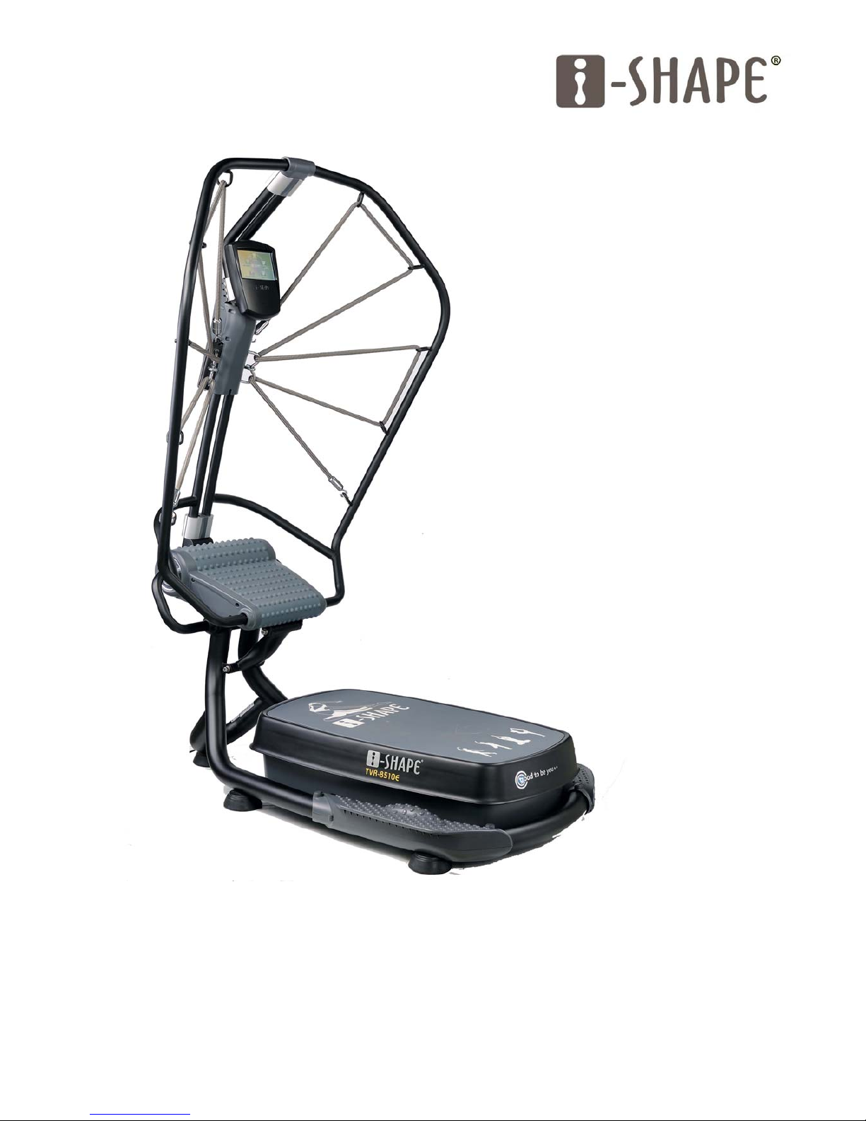
TTVVRR‐‐88551100E
E
Usermanual
©2011.06TONICFITNESSTECHNOLOGY,INC


Dear customers
We want to thank you for having chosen a i-Shape vibration machine and wish you a lot of fun and
success during training.
Please read the terms and conditions in relate to product warranty and service and help us to fill out
the warranty registration card attached.
If you have any questions please do not hesitate to contact Orbit service department on 08-62413050
or service@orbitfitness.com.au
Implied Warranty
The importer of this machine assures that this device was manufactured from high quality
materials.
Prerequisite for the implied warranty is the proper setup in accordance with the operating
instructions. Improper use and /or incorrect transportation can render the warranty void.
You may also void warranty under below circumstances:
• Damage effected by outer force
• Intervention by unauthorised parties
• Incorrect handling of the product
• Non-compliance of the operating instructions
The implied warranty is for 2 years, beginning on the date of purchase. The warranty applies
to the following parts: Frame, cable, electronic devices, motor. Foam, pads and transport
wheels are classified as wear and tear items thus only carry a limited 3 months warranty.
Postage of spare parts, transportation of product and service labour cost are not covered
under warranty. Please ask our service department for a quote before proceeding for service
and repair.
Please make sure you have the following information on hand when contacting service.
• Operating instructions or user manual
• Model number (located on the cover sheet of these instructions)
• Proof of purchase with purchase date and invoice number
The device is only intended for private use. The warranty does not apply to commercial usage.

-i-SHAPE® TVR-8510E VIBRA TION TRAINER-
C o n t e n t s
Machine Safety Instructions............................................................................................. 2
IMPORTANT SAFETY INSTRUCTIONS.......................................................... 3
Assembly Instructions..............................................................................................................5
About i-SHAPE
®
............................................................................................................................ 15
Specification........................................................................................................................................ 16
Operating Instructions........................................................................................................... 17
TOTAL BODY EXERCISE.................................................................................................. 25
The Effects of vibration training on the human body ..................... 39
REFRENCE.......................................................................................................................................... 42

-i-SHAPE® TVR-8510E VIBRA TION TRAINER-
-1-
■ ATTENTION
Do not use this product with any of following conditions and
ALWAYS consult with your physician FIRST before starting any
exercise program
1、 Acute Rheumatoid Arthritis
2、 Acute Migraines
3、 Pregnancy
4、 Cardiovascular diseases
5、 Epilepsy
6、 Heart Disorders
7、 Post Operative Wounds
8、 Other serious diseases
Please stop the program IMMEDIATELY if you feel any discomfort during
exercise.

-i-SHAPE® TVR-8510E VIBRA TION TRAINER-
-2-
Machine Safety Instructions
Information on the correct use (normal use) of the equipment and its features with the
emphasis on safety, including guidelines on the free space required for safe operation
and the importance of keeping unsupervised children away from the equipment
1. Placing the machine on a hard and level surface or using a pad underneath the machine could help
noise decrement.
2. Product noise:70db
3. Safety area of 2000mm (78in.) X 1000mm (40in.) behind the equipment
4. Rating:120 Vac,60HZ,1A
5. When lifting or handling the product use the help of another person to avoid injury. The product
weighs 121kg. (266lbs.)
6. Please read the instructions before using this product
7. Use the machine indoors only with the temperature range between 15~35℃ (60-95 deg.) and
moisture at 10%~70%.
8. Children with height below 150cm (60in.) and/or weight below 40kg (90lbs.) should not use the
product.
9. Do not place the product near any liquid
10. We recommend you use a rubberized matt underneath this product. This will aid in floor
protection and product longevity
11. Do not climb on the equipment.
12. Check the stretch rope before exercising. If any defect is found, replace the damaged parts before
use.
13. The safety of the equipment can be maintained only if it is examined regularly for damage and
wear.
14. Replace defective components immediately and/or keep the equipment out of use until repair.
15. Pay attention to components most susceptible to wear.
16. Keep unsupervised children away from the equipment.
17. Incorrect or excessive training may cause injury.
18. Ensure the unit is installed on a stable and level surface.
Class:S

-i-SHAPE® TVR-8510E VIBRA TION TRAINER-
-3-
IMPORTANT SAFETY INSTRUCTIONS
Read all instructions before using this Vibration Machine.
DANGER - To reduce the risk of electric shock:
Always unplug this appliance from the electrical outlet immediately after using and before cleaning.
WARNING - To reduce the risk of burns, fire, electric shock, or injury:
1. The machine should never be left unattended when plugged in. Unplug from outlet when not in
use, and before putting on or taking off parts.
2. Do not operate under any type of cover. Excessive heating can occur and cause fire, electric shock,
or injury.
3. Close supervision is necessary when this machine is used by, on, or near children, invalids, or
disabled people.
4. Use this machine only for its intended use as described in this manual. Do not use attachments
not recommended by the manufacturer.
5. Never operate this appliance if it has a damaged cord or plug, if it is not working properly, if it has
been dropped or damaged, or dropped into water. Return the appliance to a service center for
examination and repair.
6. Do not carry this appliance by supply cord or use cord as a handle.
7. Keep the cord away from heated surfaces.
8. Never operate the appliance with the air openings blocked. Keep the air openings free of lint, hair,
and the like.
9. Never drop or insert any object into any opening.
10. Do not use outdoors.
11. Do not operate where aerosol (spray) products are being used or where oxygen is being
administered.
12. To disconnect, turn all controls to the off position, then remove plug from outlet.
13. For commercial use
SAVE THESE INSTRUCTIONS
-i-SHAPE® TVR-8510E VIBRA TION TRAINER-
-4-
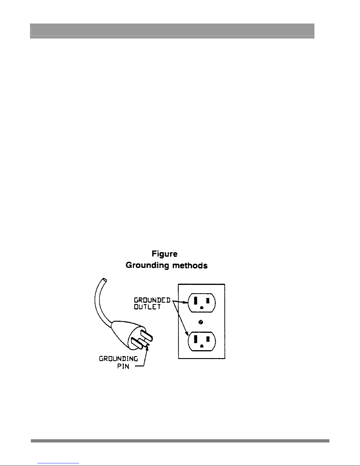
GROUNDING INSTRUCTIONS
This product must be grounded. If it should malfunction or breakdown, grounding
provides a path of least resistance for electric current to reduce the risk of electric shock.
This product is equipped with a cord having an equipment-grounding conductor and a
grounding plug. The plug must be plugged into an appropriate outlet that is properly
installed and grounded in accordance with all local codes and ordinances.
DANGER – Improper connection of the equipment-grounding conductor can
result in a risk of electric shock. Check with a qualified electrician or serviceman if you are
in doubt as to whether the product is properly grounded. Do not modify the plug provided
with the product – if it will not fit the outlet; have a proper outlet installed by a qualified
electrician.
This product is for use on a nominal 120-volt circuit and has a grounding plug that looks
like the plug illustrated in the figure. Make sure that the product is connected to an outlet
having the same configuration as the plug. No adapter should be used with this product.
-i-SHAPE® TVR-8510E VIBRA TION TRAINER-
-5-
Assembly Instructions
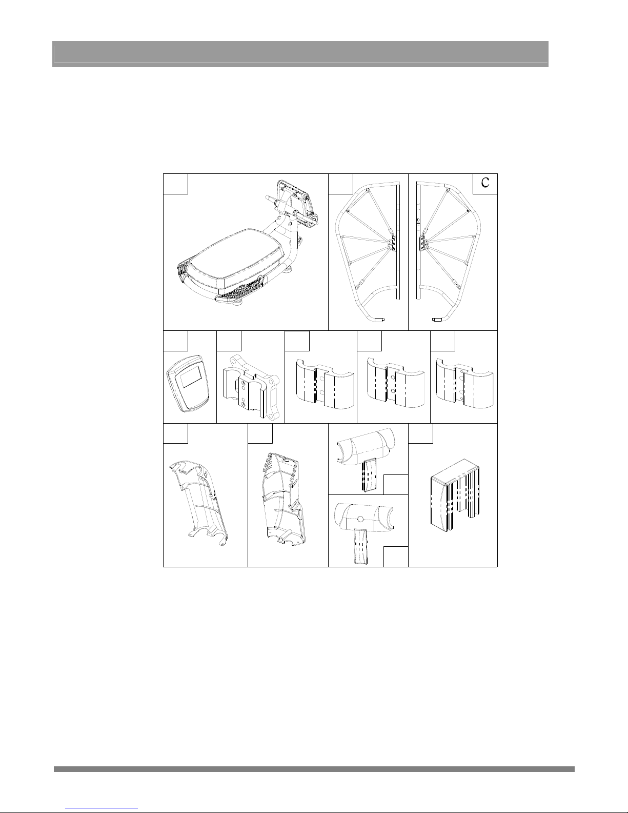
I . Inspection:
Compare the contents of the box with the component list to ensure all parts are included for
assembly.
b
j
l
a
d-1
e
f
g
i
k
h
d
(1)Components:
a:Base
x1
g:Handlebar Cover D
x 1
b:Left handlebar
x 1
h:Upper console mast cover (front)
x 1
c:Right handlebar
x 1
i:Upper console mast cover (back)
x 1
d:Console
x 1
j:Front fixed cover of top handlebar
x 1
d-1:Console mount
x 1
k:Back fixed cover of top handle bar
x 1
e:Handlebar Cover A
x2
l:Fixed cover of lower handlebar
x 1
f:Handlebar Cover B
x 2
-i-SHAPE® TVR-8510E VIBRA TION TRAINER-
-6-
(2)Parts Package:
p
s
m
w
q
t
vu
r
n
o
m:Hex socket cap screw (M6x1.0x25L)
x 8
n:Hex socket cap screw (M8x1.25x30L)
x 6
x 2
x 2
o:M10 Screw Set o1:Hex socket cap screw (M10x1.5x25L)
o2:Spring Washer (w10)
o3:Flat Washer (Ø10.4xØ16x2t)
x 2
p:Small Phillip head screws (M5x0.8x15L)
x 9
w:Small Phillip head screws (console) (M5x0.8x20L)
x4
q:Self Tapping Screw M5x10L
x 1
r:Hex socket flat head screw (M8x1.25x30L)
x 2
s:Hex Wrench (5mm)
x 1
t: 13 & 17 Spanner
x 1
u:Hex Wrench (8mm)
x 1
v:L-hex screwdriver/ wrench (6mm )
x 1
Please follow the step by step procedure to ensure proper assembly.
☆Attention:Make sure all fasteners are tightened during assembly。
-i-SHAPE® TVR-8510E VIBRA TION TRAINER-
-7-
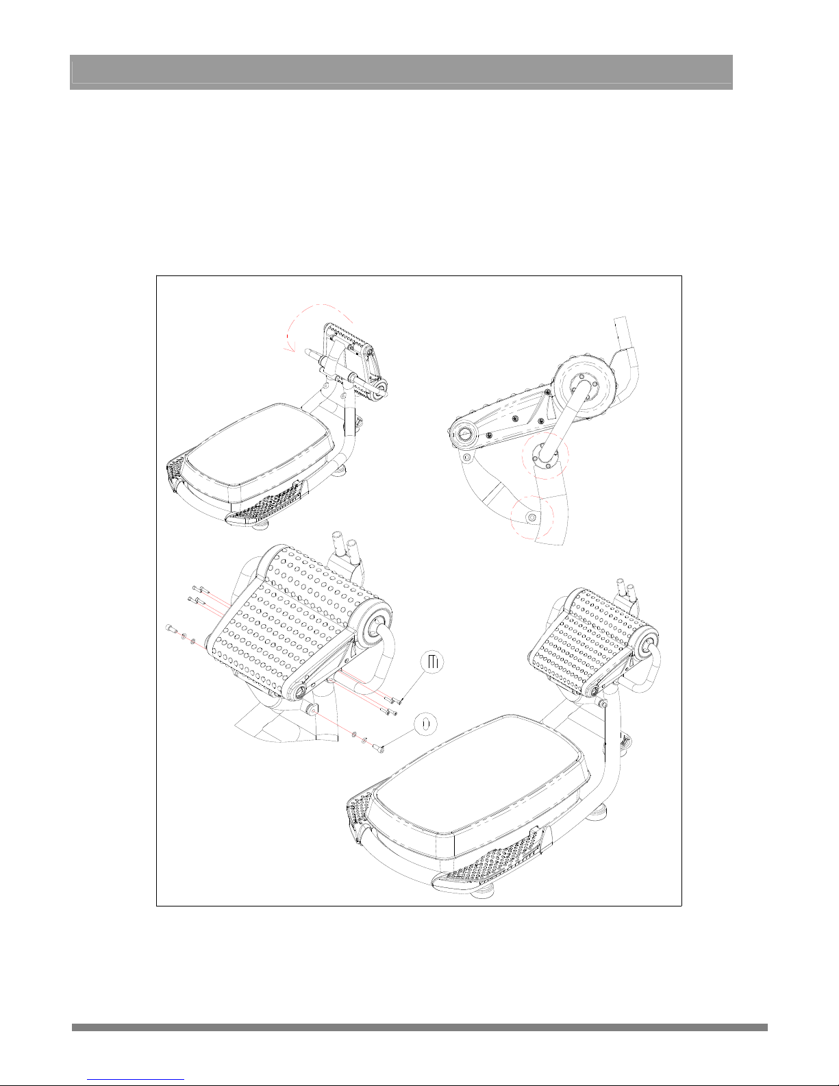
II:Assembly Steps:
1、 Frame Assembly Upper Plate Assembly
>>Take out the frame components (a),prepare screws (8pcs) (m) and M10 kit (2sets) (0)
Turn the upper plate over into the upright position aligning the screw holes【figure 1 ~ 2】
Install all screws with tools (s)、(u) into the proper position (but do not fully tighten), after
all the screws are installed, start tightening them in a clockwise direction and evenly until
all the screws are tight................【3 ~ 4】
1
3
4
2
-i-SHAPE® TVR-8510E VIBRA TION TRAINER-
-8-
2、Left、Right Handlebar Assembly Frame Assembly
>>Prepare left (b)、right(c) handlebar assemblies and screws (2pcs) (r)
Remove the screws (4pcs) from the cover on the right side of the upper plate with tool (v)
and remove the cover…………………………………………………【figure 1 ~ 2】
Connet the console harness underneath the right handlebar with the other harness on the
upper plate ..........【3 ~ 3-1】
After connecting the harness, pull up on the protruding harness on the top right handlebar
and then insert the tube into the upper plate and cover of the right upper plate..【3 ~ 4】
Tighten the right handlebar and upper plate assemblies together with screws (r) by tool
(s)…【figure 4~5】
3
5
3-1
6
3-1
4
1
2
Replace the 4 screws you initially removed and tighten the cover back into place…【figure 6】
-i-SHAPE® TVR-8510E VIBRA TION TRAINER-
-9-
>>>After assembling the right side handlebar assembly, repeat the processes for the left side
handlebar assembly.
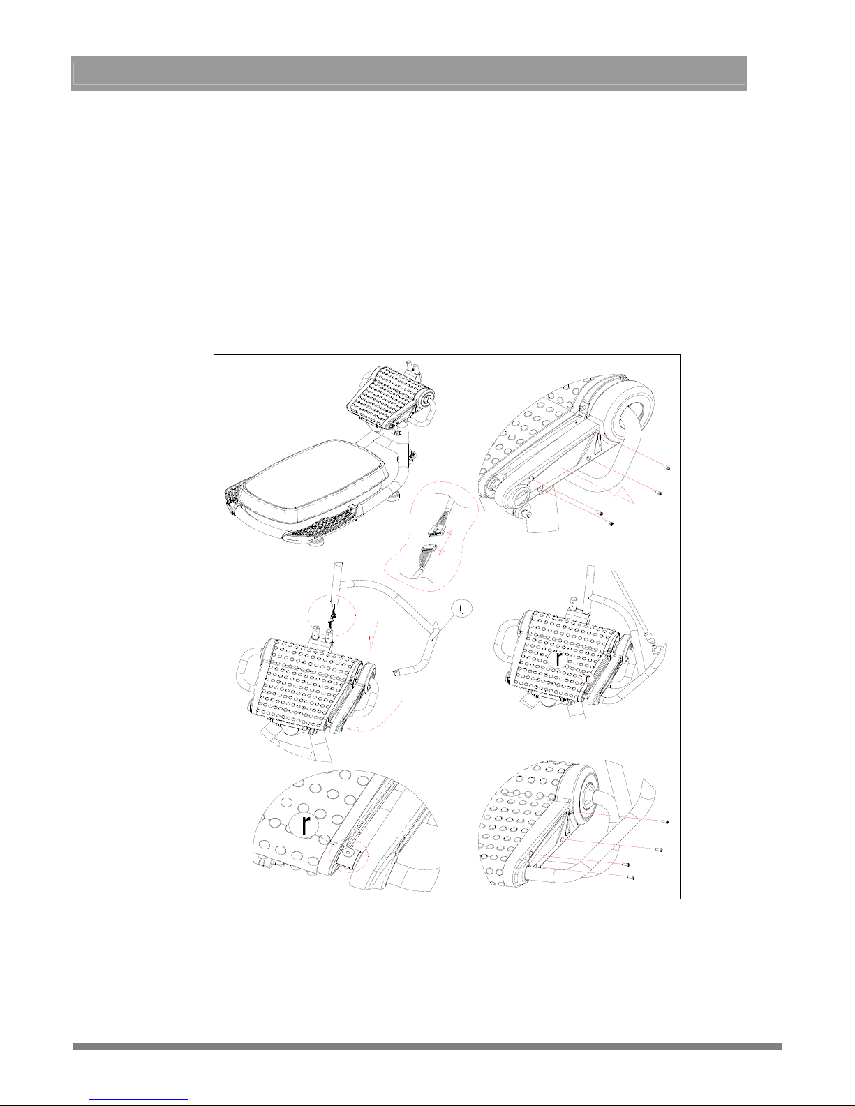
3、 Front and back top handlebar covers Handlebar Assembly
>>>Prepare handlebar covers A (e)、B (f)、Front fixed covers of top handlebar (j)、Back
fixed covers of top handlebar (k)、Screw (n) x 2pc and Self tapping screw (q)
<< Be aware the height of this assembly point is about 180cm~190cm (72 in.). Find a stable
platform to stand on for ease of assembling and be very careful.
Connect the front fixed cover of top handlebar (j) with handlebar fixture A (e)
Put the completed cover around the top of the handlebar assembly

-i-SHAPE® TVR-8510E VIBRA TION TRAINER-
-10-
Fasten the cover in place by installing handlebar cover B (f) with 2 screws (n) using
tool (v)
Install cover (k) and press it down into position on cover B (f)
Use a self tapping screw (q) to complete the installation of the cover (v)
4、 Front and back lower handlebar coversLeft、Right handlebar assembly
>>>Prepare handlebar cover A (e)、handlebar cover B (f)、lower handlebar cover (l) and
screw (n) x 2
Assemble and tighten handlebar cover A (e) and B (f) together with screw (n) as in the
below figure on the left
-i-SHAPE® TVR-8510E VIBRA TION TRAINER-
-11-
When tightened, press the lower handlebar cover (I) into the middle of covers (e)&(f) as
shown in the below figure on the right
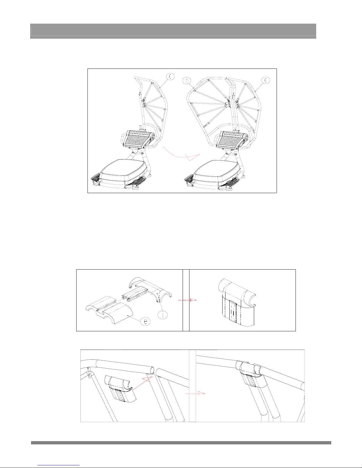
5、Console assembly、Console mount assembly、handlebar cover D、Front cover and Back cover of
handlebar adjustment Handlebar Assembly
>>>Prepare Console assembly (d)、Console mount assembly (d-1)、handlebar cover D (g)、
Front cover of upper console mast (h)、Back cover of upper console mast (i)、screw (n)、
Small Phillip head screws (p) x 9 Small Phillip head screws (w) x 4
Take out the console mount assembly,insert the cable(on the right handlebar) (c)
through the left hole of the console mount assembly (d-1) and position the mount on
the handlebar
Install the handlebar cover D
(g) behind the console mount assembly with screws (n)
x 2 by tool (v)
Plug the cable (c) into the outlet on the back of the console
 Loading...