

Page 1

OPERATION
M
M
O
M
O
M
O
L
C
R
L
C
R
L
C
R
ANUAL
2
H
M
M
M
T
L
T
L
T
L
E
T
E
R
E
T
E
R
E
T
E
R
V
e
r
s
V
e
r
s
V
e
r
s
H
H
i
o
n
i
o
n
i
o
n
2
2
2
2
2
D
D
D
E
E
E
8
8
8
2
2
0
0
0
2
Page 2

Caution
Keeping on turning on and off the instrument is absolutely
forbidden, as this will cause the disorder of the program, which will
lead to the loss of the calibrated data and the data saved by users.
Note
“7.Advanced set” in the setup menu should only be operated by
the qualified calibration personnel, therefore, this function is password
protected. Even if you know the password, you should also take high
cautions when choosing to use the options. Any wrong oper ations may
lead to the incorrect test results!
This instrument should be calibrated in the calibration lab in our
company.
Options and functions of the instrument may be advanced by our company in order to
make the instrument more accurate. Any queries regarding the instrument, please feel free to
contact us
2
Page 3
Content
.Content
Caution...................................................................................................... 2
Note................................................................................................................. 2
Chapter 1 Summary...............................................................................................................4
1 Introduction .......................................................................................................4
2 Main features .....................................................................................................4
3 Specifications .....................................................................................................5
4 Environment.......................................................................................................6
Chapter 2 Panel Overview.....................................................................................................7
1 Front Panel ........................................................................................................7
2 Rear Panel .........................................................................................................8
Chapter 3 Operation Illustration................................................................................................9
1 Turning On ..........................................................................................................9
2 Operation ..........................................................................................................10
Chapter 4 Maintenance and Measurement Basic................................................................... 21
1 Input Protection ...............................................................................................21
2 Measurement Contacts ......................................................................................21
3 Stray Capacitance............................................................................................22
Chapter 5 Contents and Warranty..........................................................................................24
1 Contents ............................................................................................................24
2 Warranty..........................................................................................................24
3
Page 4
Chapter 2 Panel Overview
Chapter 1 Summary
Thanks for purchasing our products! Please check the contents according to the last
chapter “Contents and Warranty” of the manual before put the instrument in use.
1 Introduction
Model TH2820 LCR meter is a micro desktop instrument by using microprocessor
technology. It can measure 6 basic parameters, they are inductance L, capacitance C,
resistance R, impedance Z, dissipation factor D and quality factor Q, which can fulfill the
measurement needs of various components manufacturers and maintenance technicians.
2 Main features
1. Zero Correction:
OPEN —— sweep correction of open circuit;
SHORT —— sweep correction of short circuit.
2.
Display Format:
·Direct —— actual measured value;
·∆ —— absolute delta between the measured value and the reference value;
·∆% —— delta percent between the measured value and the reference value.
3.
Range Hold:
When measuring a large number of components with the same nominal value, this
function can effectively improve the measuring speed.
4.
Comparator Function:
TH2820's built-in comparator can sort components i nto a maximum of four bins (NG, P1,
P2 and P3).
5.
Equivalent Measurement Circuit:
There are two equivalent circuit models: parallel and series.
4
Page 5
TH2820 LCR METER
3 Specifications
Parameters L-Q, C-D, R-Q, Z-Q and Z-D
Test Frequency 100Hz, 120Hz and 1kHz
Display Digits 5 digits for both primary parameters and secondary parameters
L
Measurement
C
Range
R, |Z| 1 mΩ – 999.99 MΩ
D, Q 0.0001 – 99999
∆% 0.0001% – 99999%
Accuracy (Test
Condition: within
basic
measurement
range,23°C±5°C,
<75%R.H.)
C: 0.3%
L: 0.3%
Z: 0.3%
R: 0.3%
D: ±0.001
Q: ±0.002(1+ Z
(1+ Cx/C
(1+ Lx/L
(1+ Zx/Z
(1+ Rx/R
(1+Zx/Z
Test signal level 0.3V
Ranging Mode Auto, Hold
Equivalent model Series, Parallel
Direct: actual measured value;
Display
∆ : absolute delta;
∆% : delta percent.
Correction Open and Short correction
Test Speed approx. 3 times/second
Test Terminals 5 terminals
% -9999% – +9999%
L 0.0001 µH – 99999 kH
Range of Sorting
Limits
Nominal
value
C 0.0001 pF – 99999 mF
R 0.0001 mΩ – 99999 MΩ
Z 0.0001 mΩ – 99999 MΩ
Sorting Bins NG, P1, P2 and P3
Alarm States NG, P1, P2, P3 and OFF
Weight Around 1.5 kg
Consumption Max.10 W
Power
220VAC(1±10%), 50Hz(1±5%)
100 Hz, 120 Hz 1 µH – 9.9999 kH
1 kHz 0.1 µH – 999.99 H
100 Hz, 120 Hz 1 pF – 9.9999 mF
1 kHz 0.1 pF – 999.99 µF
max
max
max
max
max
x/Zmax
+ C
+ L
+ Z
+ R
+ Z
+ Z
)(1+Dx );
min/Cx
)(1+1/Qx );
min/Lx
);
min/Zx
)(1+Qx);
min/Rx
)(1+Dx+D
min/Zx
min/Zx
rms
2
)+0.0002;
x
)(Qx+1/Qx );
(1±10%)
5
Page 6
Chapter 2 Panel Overview
Note:
1. Accuracy of D and Q are delta absolute deviations, the rest are delta percent deviations;
2. Suffix with
value, suffix with
is the actual measured value of this par ameter, suffix with
X
is the minimum value;
min
is the maximum
max
Parameter
C
C
L
L
Z
Z
Z
max
max
min
max
min
max
min
= R
Range
Auto
80µF/f
150pF/f 150pF/f 1900pF/f 10nF/f 100nF/f
159H/f 159H/f 25.3H/f 2.53H/f 253mH/f 25.3mH/f
0.32mH/f
1MΩ 1MΩ 159kΩ 15.9 kΩ 1.59kΩ 159Ω
1.59Ω 15.9kΩ 1.59kΩ 159Ω 15.9Ω 1.59Ω
; Z
max
min
Range0 Range1 Range2 Range3 Range4
1000pF/f
2.53H/f 0.25H/f 25.3mH/f 2.53mH/f 0.32mH/f
= R
min
0.1µF/f 1µF/f 10µF/f 80µF/f
Range Hold
1µF/f
3. In order to maintain good test accuracy, proper open and short circuit corrections should
be taken under current measurement condition and measurement fixture.
4 Environment
1. Please do not operate the instrument under the following environment conditions, as
any of them will directly affect measuring precision or damage the instrument:
(1) Please do not operate the instrument in the places where is vibrative, dusty,
under direct sunlight, or where there is corrosive air.
(2) Although the equipment has been specially designed for reducing the noise
caused by AC power, a place with low noise is still recommended. If this cannot
be arranged, please make sure to use power filter for the instrument.
2. Please store the instrument in the place where temperature is between -25°C and
50°C. If the instrument will not be put in use for a while, please have it properly pack ed
for storing.
3. Operation environment for securing measuring precision requirement:
Temperature: 0°C ~ 40°C
Humidity:≤ 85%R.H.
4. Pre-heat the instrument about 10 minutes before starting measuring.
6
Page 7
Chapter 2 Panel Overview
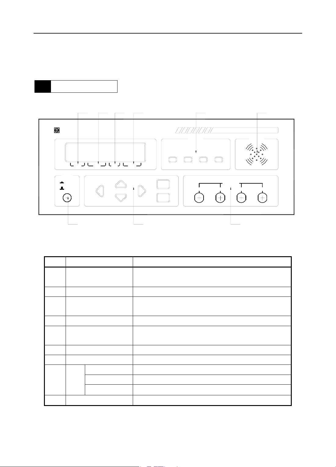
1 Front Panel
1234 5 6
TONGHUI
ELECTRONICS
TH2820 LCR METER
SORTING
NG P1 P2 P3
TH2820 LCR METER
BUZZER
PARA DISP RANGE
POWER
ON
OFF
FREQ
SETUP
START
HD HS LS LD
UNKNOWN
789
Figure 2-1 Front panel
Following is the description of items 1~9 in Figure 2-1.
No Name Description
1 Parameter
2 Frequency
3 Display Mode
4 Range Displaying range state: Auto, Hold or current range.
5 Bins Indication
6 Buzzer
7 Test Terminals HD, HS, LS and LD
Cursor keys Function table moving and rolling
8 Key
Setup key Entering function table setting
Start key The executing confirmation of command
9 POWER Power switch
Displaying current measured parameters:
L-Q, C-D, R-Q, Z-Q, Z-D or AU TO
Displaying current frequency:100 Hz, 120 Hz or1 kHz
Displaying current display mode of the primary
parameter: DIR, ∆ or ∆%
NG: No-good; P1: Pass1; P2: Pass2; P3: Pass3;
P1, P2, P3 Priority is lower in turn.
Table 2-1 Front Panel Descriptions
7
Page 8
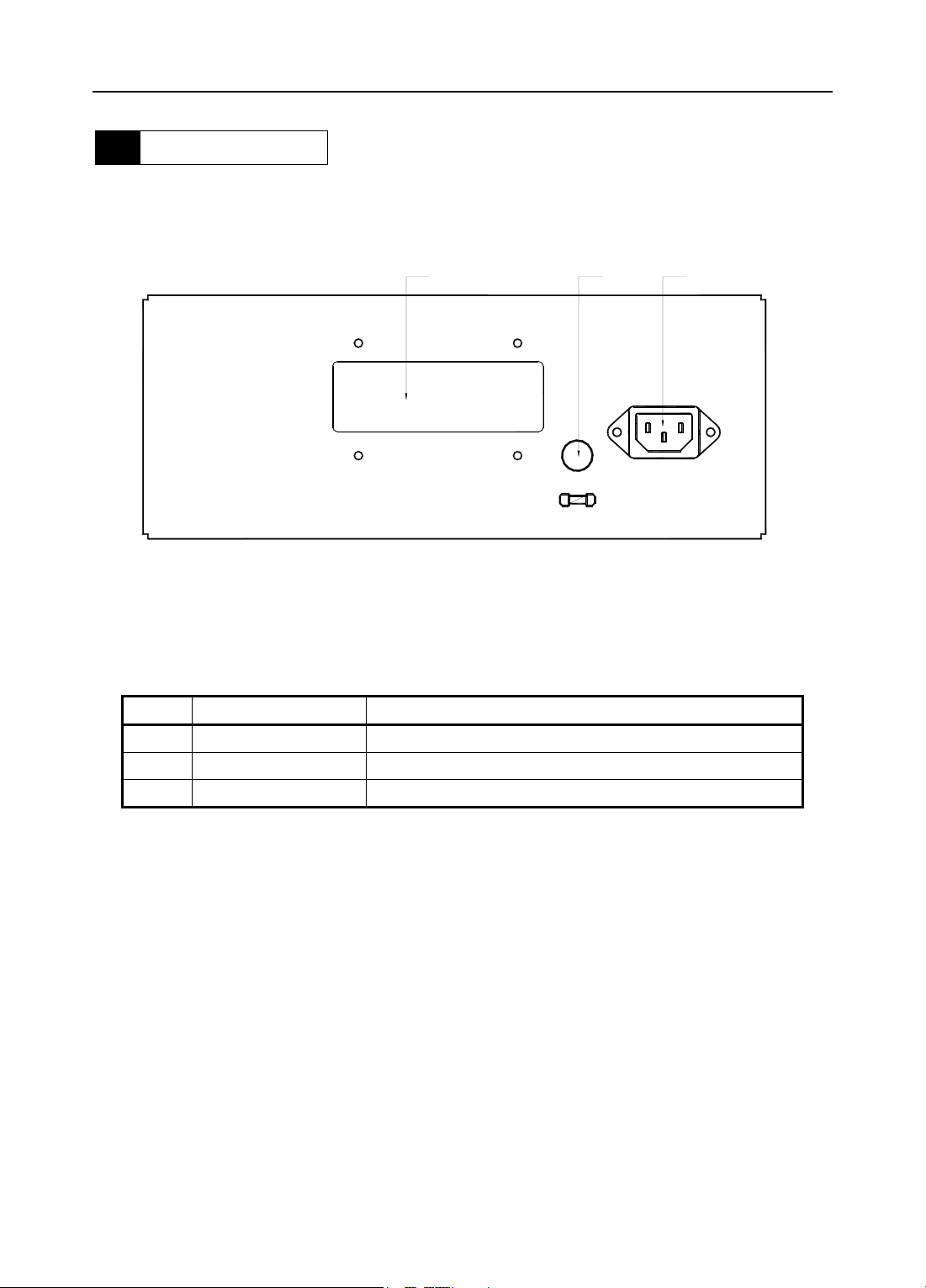
2 Rear Panel
Chapter 2 Panel Overview
123
FUSE
INPUT
1A
AC
220V
50Hz
Figure 2-2 Rear panel
Item Name Description
1 Plate Production date, model and serial number
2 Fuse Holder 1A 250 Vac slow blow fuse.
3 Power Receptacle 220 Vac 50 Hz
Table 2-2 Rear Panel Descriptions
8
Page 9
Chapter 3 Operation Illustration
Chapter 3 Operation Illustration
This chapter will introduce how to oper ate this instrument in details, please r ead it carefully
before operating, in order to avoid any damages to the instrument or dangers to the safety.
1 Turning On
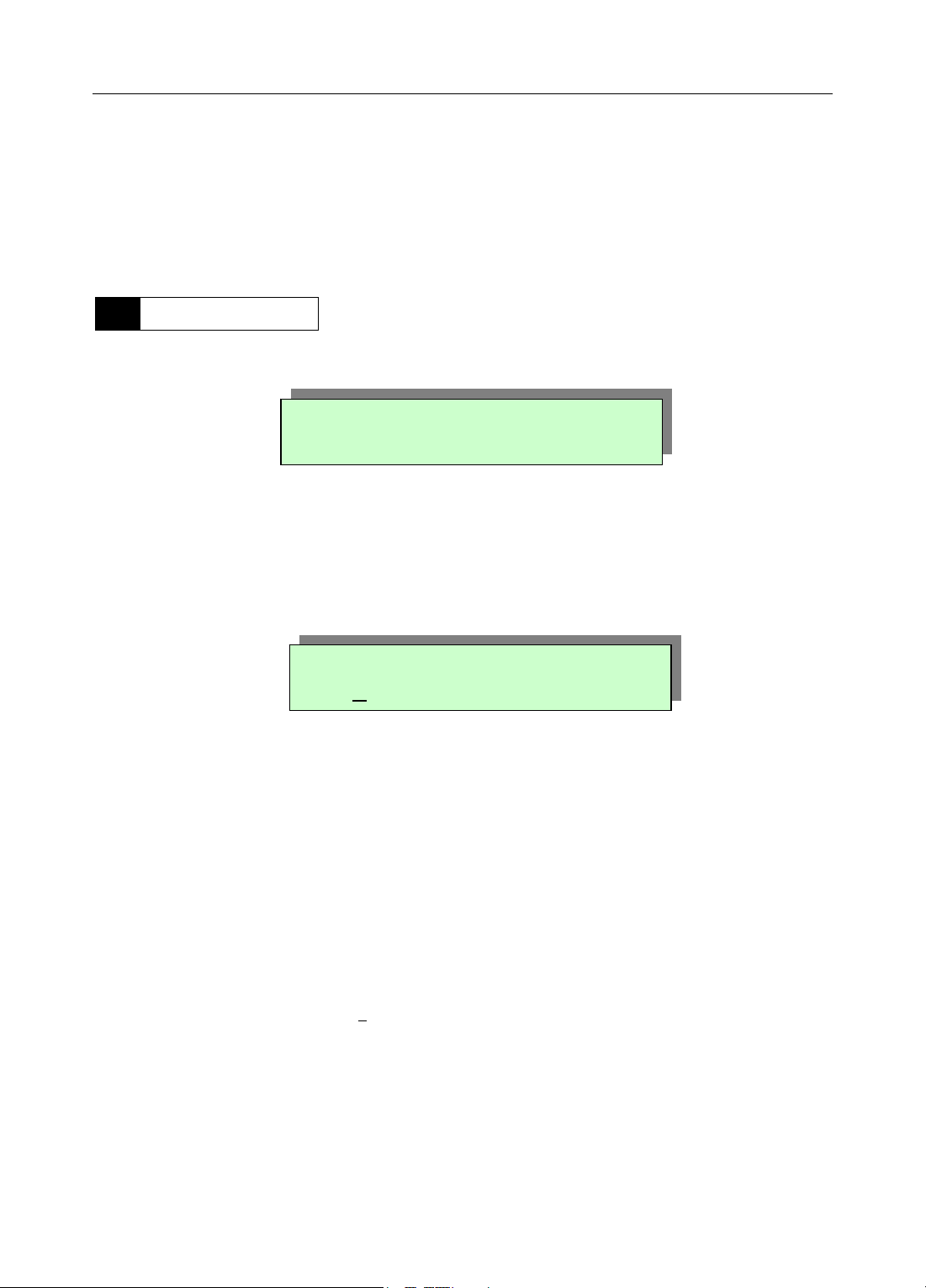
a.Display company name and version,the indicator lamps of P1、P2、P3、NG flash in turn.
b. Starting power-on self tests
1)EEPROM Memory checking
2)ADC AD converter checking
c. Entering measuring state after self tests
TH2820 LCD LCR METER
Ver1.0
Figure 3-1 Turning on information
Cs:0.0030pF D:1.0000
C-D 100Hz Dir AUTO
Figure 3-2 Measuring state
The factory settings are listed as follows and can be reseted according to the
operation description in next paragraph.
(1) Parameter: C-D;
(2) Frequency: 100 Hz;
(3) Display: Dir(direct reading);
(4) Range: AUTO(automation);
(5) Equivalent: SER(serial);
(6) Alarm Bin: P1(Pass #1);
(7) LCZ automation: OFF;
(8) Cursor:
9
Page 10
TH2820 LCR METER
2 Operation
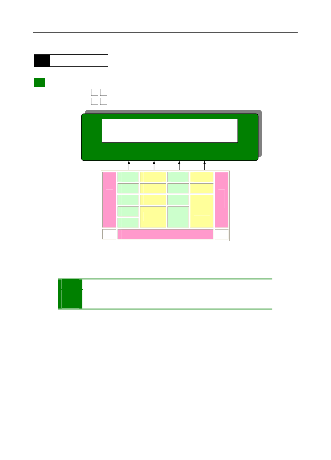
1 Direct function setup —— Parameter, frequency, display and range:
a) Press keys to move the cursor and select one of the four direct functions.
b) Press keys to select:
Cs:0.0030pF D:1.0000
-D 100Hz Dir AUTO
C
Para Freq Disp Rang
L-Q 100Hz Dir AUTO
C-D 120Hz ∆ HOLD
R-Q 1kHz ∆%
Z-Q
Z-D
A.Parameter:
Unit descriptions:
L µH mH H kH
C pF nF µF mF
R/Z MΩ Ω kΩ MΩ
1. Z is the absolute value of impedance. Measurement value of L, C or R may be
positive or negative. Negative capacitance v alue means t hat the device unde r test
is actually an inductor; also negative inductance value means that the device
under test is actually a capacitor. In theory R should be positive constantly, under
some condition, R maybe negative due to over zero correction. Please carry out
correct zero correction.
2. The maximum number of display digits is 5, but 5 digits is not always av ailable and
4 digits is displayed sometimes. The conversion is described in the following table:
Table 3-1 OSD Direct Function Items
Table 3-2 units
10
Page 11
Chapter 3 Operation Illustration
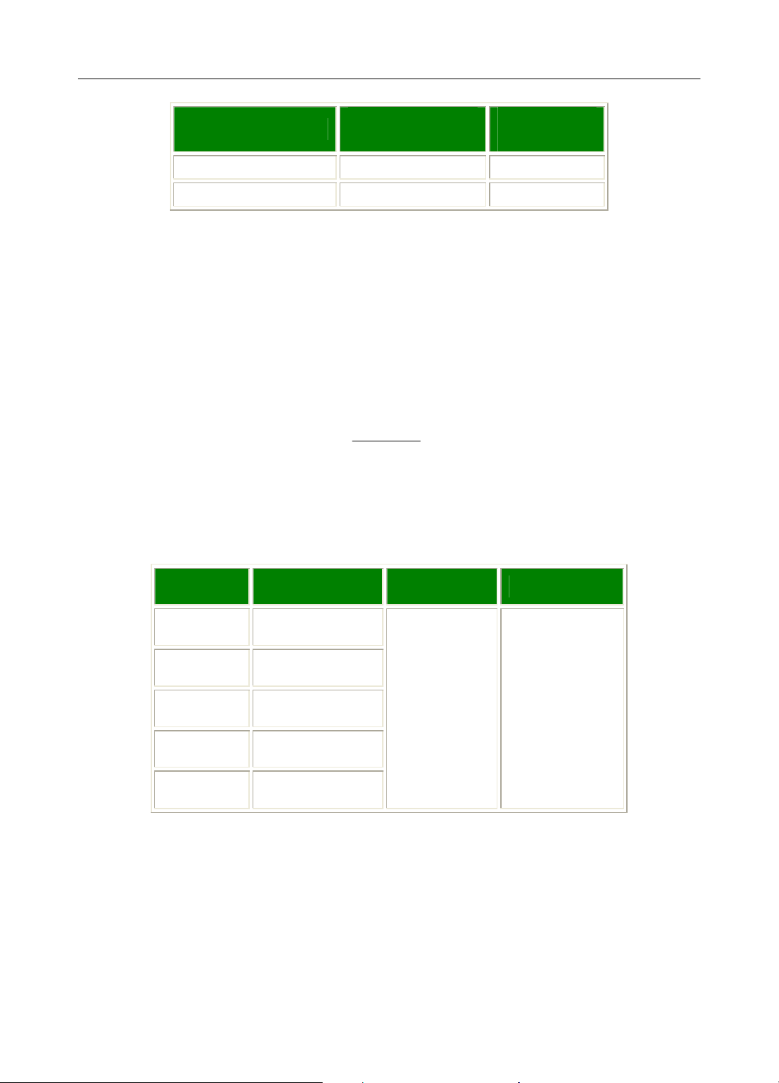
−
=
−
Previous display digits
First two digits of
current value
Current display
digits
4( Bigger first two digits) <29 5
5(Smaller first two digits) >32 4
Table 3-3 The conversion of display digits
B.Display mode —— Direct reading(Dir), Absolute delta(∆), Percent delta(∆%)
1. (∆)delta absolute deviation measurement:
XX
stdx
:reference value
std
X
:Measured value X
x
∆
2. (∆%) Delta percent deviation measurement:
XX
=∆
stdx
X
std
%100% ⋅
C. Measurement range
1. The instrument has 5 measurement ranges. The measurement range is selected
according to the impedance even if measurement parameter is capacitance or
inductance.
Range No. Range resistor |Z| up |Z| down
0 100kΩ
1 10kΩ
2 1kΩ
3 100Ω
4 10Ω
Ï
32kΩ
Ï
3.2kΩ
Ï
320Ω
Ï
32Ω
Ï
Ð
30kΩ
Ð
3kΩ
Ð
300Ω
Ð
30Ω
Ð
Table 3-4 Range NO., Range Resistor and Up and Down Limits of Impedance.
2. When measurement range is set to AUT O, the instrument first estimates if current
range is the correct range, if it’s the correct range, then the instrument calculates
and displays the measurement value, otherwise instrument has to change to the
correct range and start measurement again. Therefore, in range AUTO mode,
one more measurement will be taken if the measurement range has to be changed.
11
Page 12
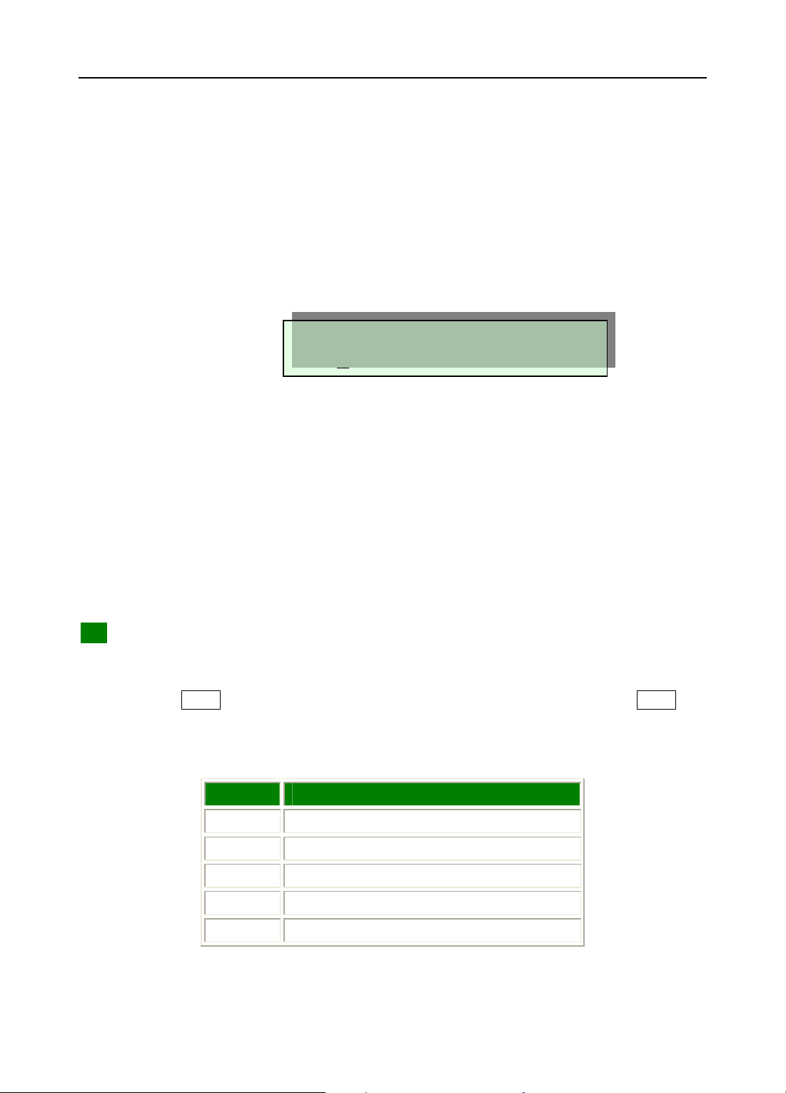
So more time is taken in range AUTO mode.
3. If a large number of devices under test belong to the same range, the correct
range can be locked to raise the measurement speed. For the instrument do not
have to take any time to find the correct the range.
4. When measurement range is set to HOLD, if the impedance under test exceeds
the effective measuring range of the locked measurement range, overload
symbols will be displayed as shown in Figure 3-3:
Cs:------ F D:1.0000
C-D 100Hz Dir HOLD
Figure 3-3 Overload
Note: If the measurement value exceeds the display range of the instrument, overload
symbols will also be displayed.
5. How to calculate the measurement range
Example: Suppose capacitance C=210pF, dissipation D=0.0010 and test
frequency f=1kHz.
Solution: We can calculate: Z
From Table 3-4, you can find the correct measurement range is range 2.
2 Indirect Functions Setup:
Indirect functions are Clear “0”, Sorting, Auto-LCZ, Buzzer, Change cursor, Advanced
set, and State save & exit.
Press Setup key to enter the setup menu in measurement state. Pressing Setup key
again, the instrument returns back to the measurement state.
Key functions are defined as follows:
= 757.9
x
TH2820 LCR METER
KEY 1st Function /2nd Function
START Enter
Back to main menu/ Move left
Enter sub menu / Move right
Move up / Add 1
Move down / Minus 1
Table 3-5 Key Functions
12
Page 13
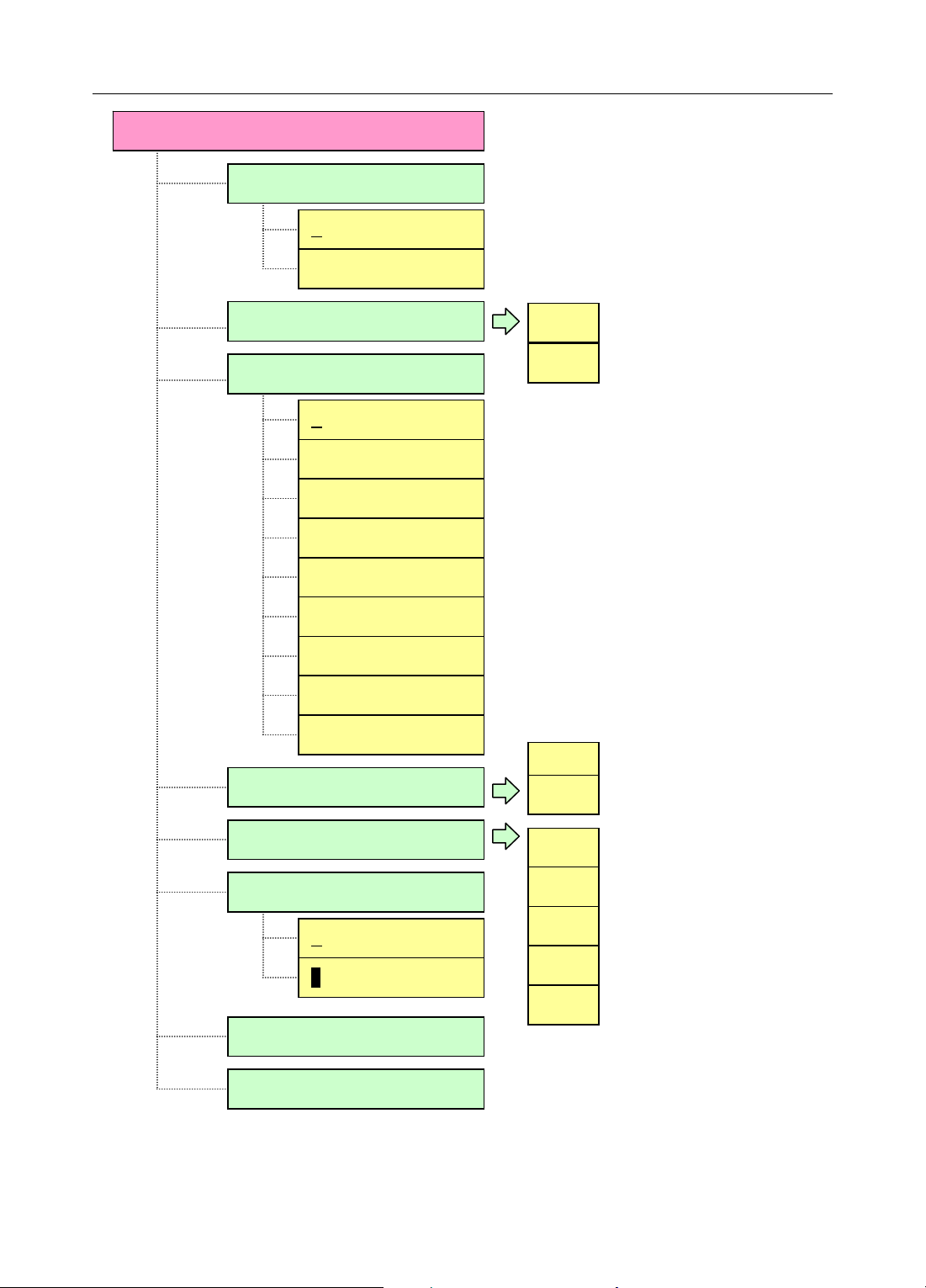
Chapter 3 Operation Illustration
Menu
1.Clear “0”
1.1 OPEN
1.2 SHORT
2.Equivalent
SER
3.Sorting
PAL
3.1 P1min
3.2 P1max
3.3 P2min
3.4 P2max
3.5 P3min
3.6 P3max
3.7 Q min
3.8 D max
3.9 L/C/R/Z
4.Auto-LCZ
std
OFF
ON
5.Buzzer
P1
6.Change cursor
C
7.Advanced set
P2
P3
NG
OFF
8.State save & exit
Figure 3-4 OSD Menu Tree
13
Page 14
TH2820 LCR METER
p
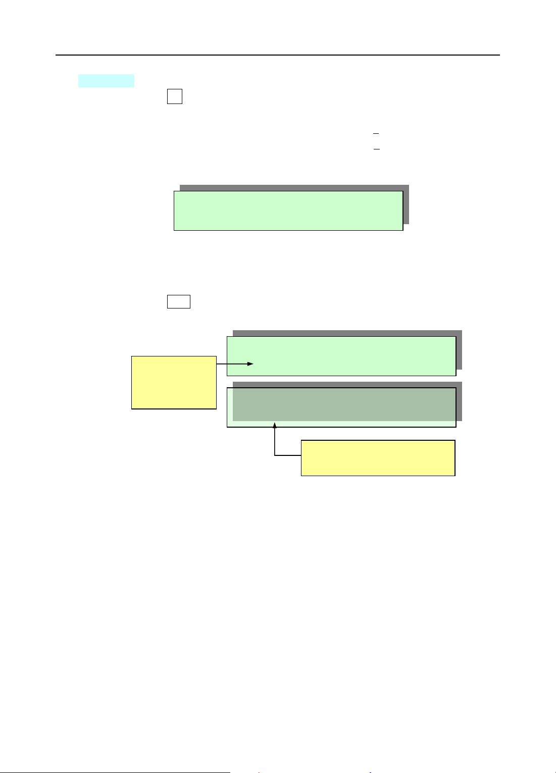
1.Clear “0”
a) Press
b) TH2820 can select OPEN or SHORT automatically:
c) When a component is connected to the terminals, the following information is
button to enter clear “0” function.
When terminals are opened, cursor flashes under
When terminals are shorted, cursor flashes under
displayed as shown in figure 3-5:
1.1 OPEN;
1.2 SHORT;
Open or short
Connector!
Figure 3-5 Open or short
Remove the component and select the open correction; Or insert the
shorting plate and select the short correction.
d) Press Start key to start zero correction.
e) The following information is displayed during zero correction:
Notes:
1. The correction function must be used in order to measure the device under test accurately. OPEN
correction capability cancels errors due to the stray admittance (G, B) in parallel with the device
under test. SHORT correction capability corrects for the residual impedance (R, X) in serial with
the device under test. Perform correction again when measurement conditions are changed such
as test fixture or environment temperature.
2. OPEN and SHORT correction should be performed at the same time.
3. The SHORT correction may be failed, if the measurement contacts are not shorted reliably. Make
sure the test terminals are shorted, and then perform SHORT correction again.
4. Sweep correction —— All ranges at each frequency are corrected. The correction data is stored in
non-volatile memory. So you don’t have to perform correction again, if onl y fr eq uen c y is chang ed .
Open correction
passed at 1kHz,
range 0.
Figure 3-6 Zero correction in process
Clearing... OPEN
Pass 1kHz Range:0
Clearing... SHORT
Fail 1kHz Range:0
Short correction failed with two
bee
s at 1kHz, range 0.
14
Page 15
Chapter 3 Operation Illustration
2. Equivalent
a) Press
b) Use
c) Press or to return.
Notes:
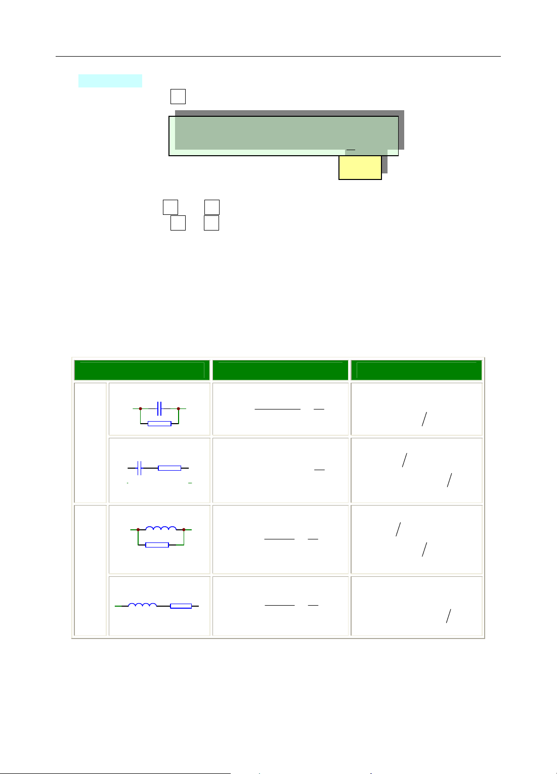
1. The actual capacitor, resistor and inductor are not the ideal capacitor, resistor and
inductor. Normally, a component has the characteristics of the resistor and the
reactor at the same time. The actual component is composed of an ideal resistor
and reactor (ideal inductor or capacitor) in series or parallel equivalent circuits.
2. The values in the two different equivalent circuits can be converted to each other
using the following formulas in Figure3-6. The values are different due to the
quality factor Q (or the dissipation factor D).
button to enter equivalent option;
1. Clear “0”
2. Equivalent
Figure 3-7 Equivalent Circuits
SER
PAL
and buttons to select SER or PAL;
Circuit Mode Dissipation Factor Conversion
Cp
D
1
π
2
1
==
QRfC
Pp
+=
PS
C
1
SS
P
Q
1
==
QR
SP
PS
Cs
Lp
Rp
Rs
2 ==
π
CfRD
fL
2
π
D
P
L
Lp
L: Inductor C: Capacitor f: Frequency
R: Resistor D: Dissipation factor Q: Quality factor
Suffix s: Series Suffix p: Parallel
Rp
Figure 3-6 Conversions between Series and Parallel Circuits
D
R
2
π
15
1
S
S
==
QfL
+=
SP
2
)1(
CDC
PS
22
)1(
DDRR
+=
2
)1(1
CDC
+=
+=
+=
2
+=
SP
22
)1(
DDRR
2
)1(1
LDL
PS
22
)1(
DDRR
+=
)1(
LDL
SP
22
)1(
DDRR
Page 16
TH2820 LCR METER
3. Form the above table, we can see that the parameters have relations with D2 or
2
Q
, and the value of D2 will directly affect the values of the parameters. Take the
following capacitor as an example:
Example: The capacitance in series model is Cs = 0.1µF, calculate the capacitance
in parallel model for (a) D1 = 0.0100, (b) D2 = 0.1000 and (c) D3 = 1.0000.
Solution: According to the formulas in table 3-6, the capacitances in parallel
model are:
Cp1 = 0.09999µF
Cp2 = 0.09901µF
Cp3 = 0.05µF.
You can find that, when D<0.01, the difference between Cs and Cp is very
small, but while D>0.01, the difference will be very obvious. For example,
when D = 0.1, the difference between Cs and Cp in percentage is approx 1%,
while D = 1, the difference in percentage will be about 50%.
4. The following description gives some practical guidelines for selecting the
capacitance measurement circuit mode.
a) We can select the circuit mode according to the variation of D atp two different
frequencies. If the dissipation factor of a capacitor increases with the increase of the
test frequency, series circuit mode should be selected. If the dissipation factor
decreases with the increase of the test frequency, parallel circuit should be used. For
inductor, the situation is just in the opposite side. In fact, D is impossible in direct ratio
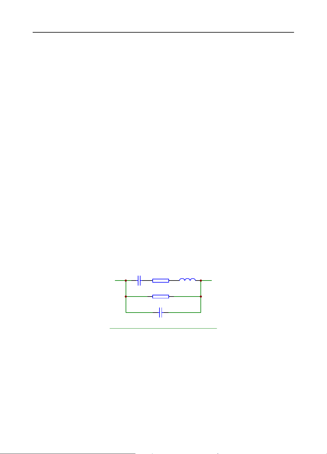
with the test frequency. From Figure 3-8, we can find that Rp and Rs exist at the same
time. If Rs is more significant than Rp, series mode is selected; If Rp is more
significant than Rs, parallel mode is more suitable.
Cx
Rs
Rp
Lo
Cs
Figure3-8 Equivalent circuit of an actual capacitor
Where,
Cx: ideal capacitor
Rx: resistance of the leads
Lo: inductance of the leads
Rp: insulation resistance across the capacitor
Co: stray capacitor across the capacitor.
For a given frequency F, Cs and Cp can be calculated.
16
Page 17

Chapter 3 Operation Illustration
b) Select the equivalent circuit according to the actual application in circuits. If a
capacitor is used as a coupling capacitor, series circuit mode is the best choice; if a
capacitor is used in a LC oscillator, then parallel circuit mode is more suitable.
c) When there is no proper information available, please make decision according to
followin g rules:
For low impedance component(such as large capacitor or small inductor), the
series equivalent circuit mode should be used.
For high impedance component(such as small capacitor or large inductor), the
parallel equivalent circuit mode is the appropriate choice.
In general,when |Z|<10Ω,series equivalent measurement circuit should be
used; When |Z| > 10kΩ,parallel equivalent measurement circuit should be used;
When 10Ω<|Z|<10kΩ,please choose proper equivalent measurement circuit
according to the actual situation.
17
Page 18
3. Sorting
a) Press button to enter sorting function son menu.
b) Use button to select a digit to be changed. Press or keys to change the
digit value or sign (+/-).
c) Press button to select digit position or return, value is saved automatically
when return.
d) Press Start key, you can directly return from value setup state or enter the unit
setup state(When you setup nominal value).
Notes:
1. L, C, R and Z have the same sorting bin limits, but each nominal should be set
respectively.
2. The nominal value is determined by what kind of parameters is currently
measured and displayed. Nominal Cstd is for C-D, Lstd for L-Q, Rstd for R-Q,
and Zstd for Z-Q/Z-D.
3. Sorting function is enabled under any display mode(Dir, ∆ or ∆%).
4. In order to sort correctly, make sure that high limit must be greater than low
limit for a pair of bin limits.
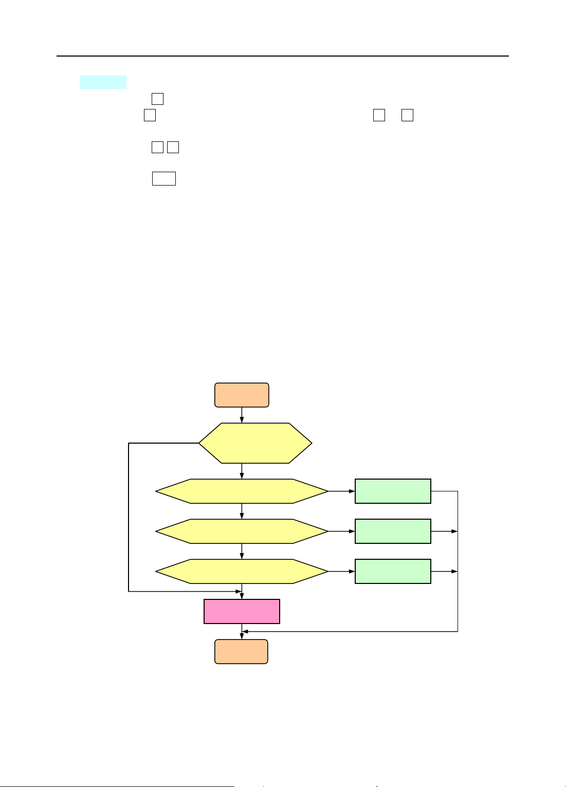
Flow Chart of Sorting
5. Flow Chart of Sorting:
N
P1min≤∆%≤P1max
P2min≤∆%≤P2max
P3min≤∆%≤P3max
NG (FAIL)
Figure3-9 Flow chart of sorting
TH2820 LCR METER
Begin
D≤Dmax
Or Q≥Qmin
Y
Y
PASS 1
N
Y
PASS 2
N
Y
PASS 3
N
END
18
Page 19
Chapter 3 Operation Illustration
4.LCZ auto
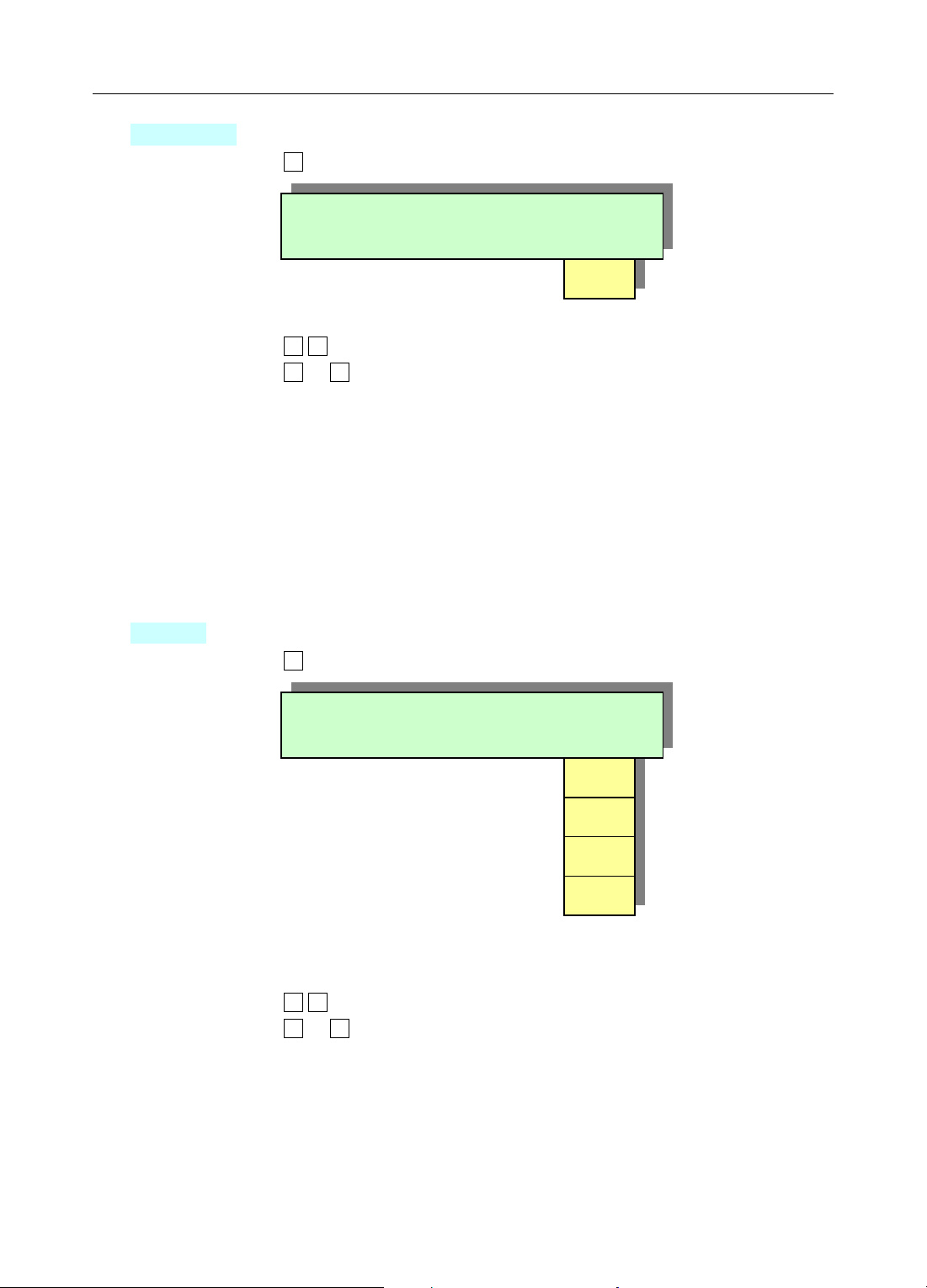
a) Press button to enter Auto-LCZ option:
3.Clearing
4.Auto-LCZ OFF
Figure3-10 Auto-LCZ option
b) Press buttons to select ON/OFF.
c) Press or to return
Notes:
1. When |Z|>25MΩ, Z/Q is selected automatically.
2. When |Z|<80mΩ, Z/Q is selected.
3. When 80mΩ< |Z| <25MΩ:
If Q < 0.125, Z/Q is selected;
If Q ≥ 0.125, L/Q is selected;
If Q ≤ -0.125, C/D is selected.
5.Buzzer
a) Press button to set buzzer state:
4.LCZ auto OFF
5.Buzzer OFF
Figure 3-11 Set buzzer state
b) Press keys to select P1, P2, P3, NG and OFF states.
c) Press or key to return, selected state is saved automatically.
ON
NG
P3
P2
P1
19
Page 20

TH2820 LCR METER
6.Change cursor
a) Press key to set cursor shape:
b) Press or keys to select _ or ■.
c) Press or key to return .
7.Advanced set
This function needs password. For instrument calibration only.
8.State save & exit
1. The following states are stored in non-volatile memory as the initial states when
TH2820 is turned on next time:
2. Instrument returns to measuring state after saving the states
5.Buzzer OFF
6.Change cursor _
Figure3-12 Set cursor shape
① Measurement parameter;
② Measurement frequency;
③ Display mode;
④ Equivalent circuit model;
⑤ Auto-LCZ state;
⑥ Position of cursor.
*Note:
Th2820 will exit the setup menu by pressing Setup or Start key, but the changed states
can not be saved.
20
Page 21
Chapter 4 Maintenance and Measurement Basic
Chapter 4 Maintenance and
Measurement Basic
1 Input Protection
Internal circuit protection is designed to protect the instrument from damage by a charged
capacitor,
When a charged capacitor is connected to the UNKNOWN terminals. The maximum
capacitance is:
C
MAX
Where, U is the capacitor voltage (V), C
the capacitor voltage U.
Typical values of U and C C
5.2
=
2
U
is the maximum capacitance in Farads under
MAX
are shown in Table 4-1:
MAX
U C
1000V ≤ 2µF
400V 16µF
125V 160µF
40V 1600µF
12.5V ≤16000µF
Table 4-1 Typical values of U and C
MAX
MAX
2 Measurement Contacts
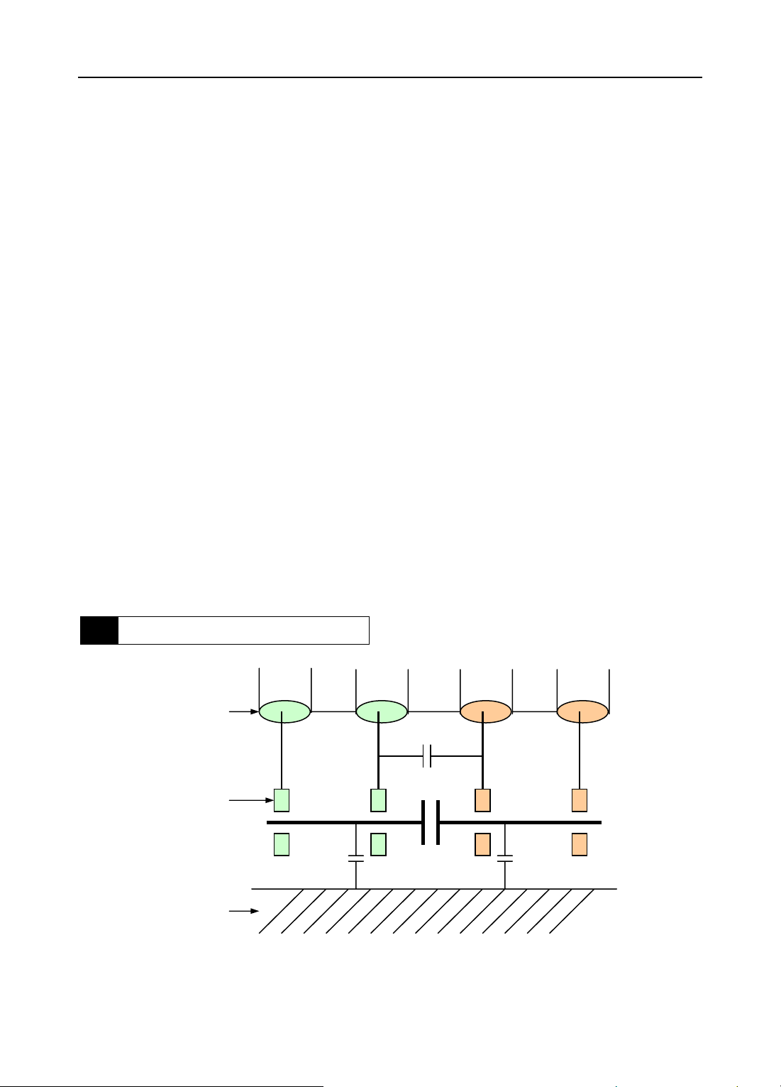
TH2820’s test terminals consists of four coaxial cables, the outer shield conductor of each
cable is connected with Ground. Sometimes we also call it five test terminals. Five terminals are
described as follows:
HD: High current drive
LD: Low current drive
HS: High potential sample
LS: Low potential sample
⊥: Grounded shield
The ground shields are used reduce influence of stray capacitance and electromagnetic
21
Page 22
TH2820 LCR METER
disturbance. HD, HS and LD, LS should be connected at the lead of the component under test in
order to reduce the influence of cable resistance and contact resistance especially in D
measurement. When measuring low impedance, the drive terminals and sense terminals should
be connected to leads of component separately so as to avoid the influence of lead resistance.
*Note:
In other words, HD, HS and LD, LS cannot be connected before connecting to the
component otherwise measurement error will be caused. Refer to Figure 4-1.
If contact resistance and leads resistance R
example R
< Zx/1000, and the accuracy required is 0.1%), then HD, HS and LD, LS can be
lead
connected together before connecting to the component under test (two-terminal
measurement).
Test cable or fixture should meet the following requirements:
1. T o minimize stray capacitance of the test leads, especially when component of high
impedance is measured. (Such as small capacitor). How to eliminate the stray
capacitance, please refer to the next paragraph.
2. To minimize contact resistance between contacting terminals and the device under
test. Make sure that four- terminal measurement circuit configuration is
constructed.
3. OPEN and SHORT correction can be performed. Zero correction is a very effective
way to reduce the influence of stray impedance.
are far less than the impedance tested (for
lead
3 Stray Capacitance
Shield
Test terminal
Metal conductor
HD HS LS LD
C
d
C
h
C
x
Figure 4-1 Capacitance to Ground
22
C
l
Page 23
Chapter 4 Maintenance and Measurement Basic
p
When component of high impedance (for example small capacitor) is measured, the
influence of stray capacitance cannot be ignored. As shown in Figure 4-1, Cd is in parallel with
Cx. When there is conductor board under the tested component, capacitance Ch is connected
in series with Cl, then Ch and Cl are connected to with Cx in parallel. Cd, Ch and Ci will cause
errors to measurement values. To place a grounded conductor between the high terminal and
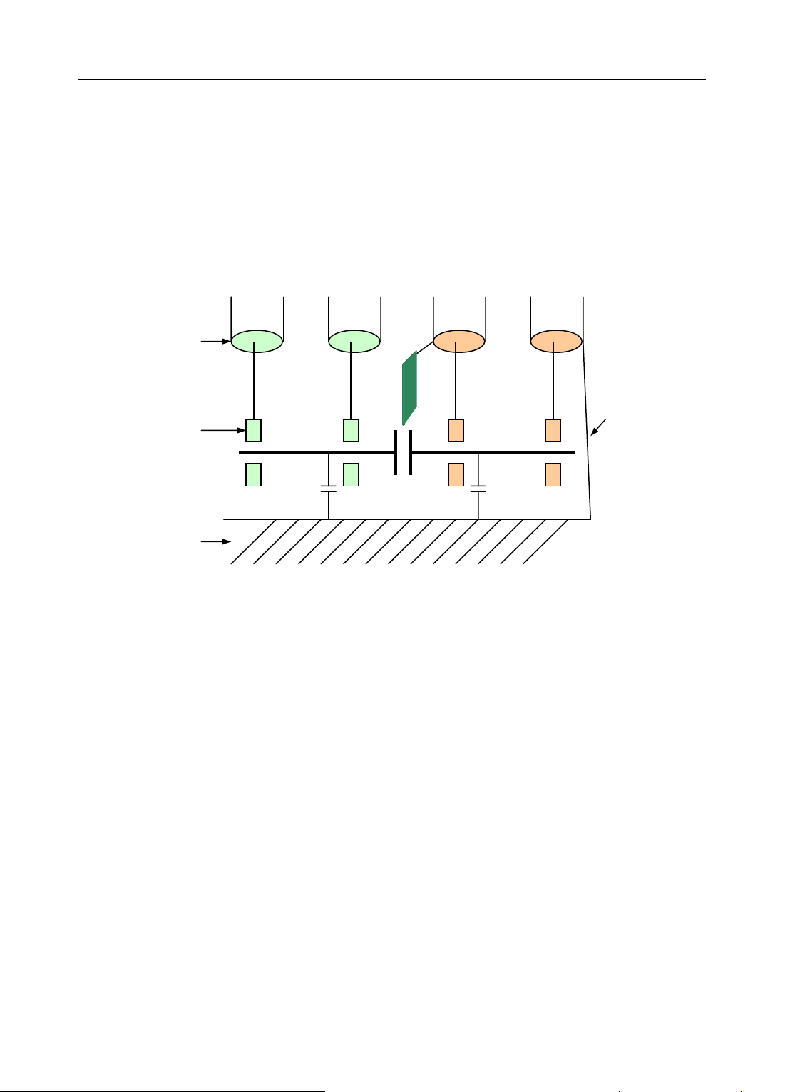
the lower terminal can reduce capacitor Cd. In addition, if the conductor board is grounded, Ch
and Cl will be eliminated.
Shield
LDLSHD HS
Test terminal
Shield
late
Connected
to ground
Metal conductor
CxCh Cl
Figure 4-2 Reducing Capacitance to Ground
When low impedance component (for example small inductor or large capacitor) is
measured, a larger current will flow through the test wires HD and LD. Electromagnetic
coupling between the test wires will become the main source of error. Normally, the contact
resistance will affect resistance part of the component while the electromagnetic coupling will
affect reactance part of the component under test. The best way to eliminate the
electromagnetic coupling is to adopt the four-terminal pair connection. But this instrument
adopts the four-terminal connection instead of the four-terminal pair connection. A
double-twisted test cable is also helpful to eliminate electromagnetic coupling, because the
currents flew through HD and LD have the same magnitude but opposite directions, the
magnetic fields induced by HD and LD cancel each other so no external magnetic fields are
generated around the cable. There are two methods to make a double-twisted cable. The first
method is that HD is twisted with LD and HS is twisted with LS. The other method is to twist the
four wires directly. The first method is recommended.
23
Page 24
Chapter 5 Contents and Warranty
1 Contents
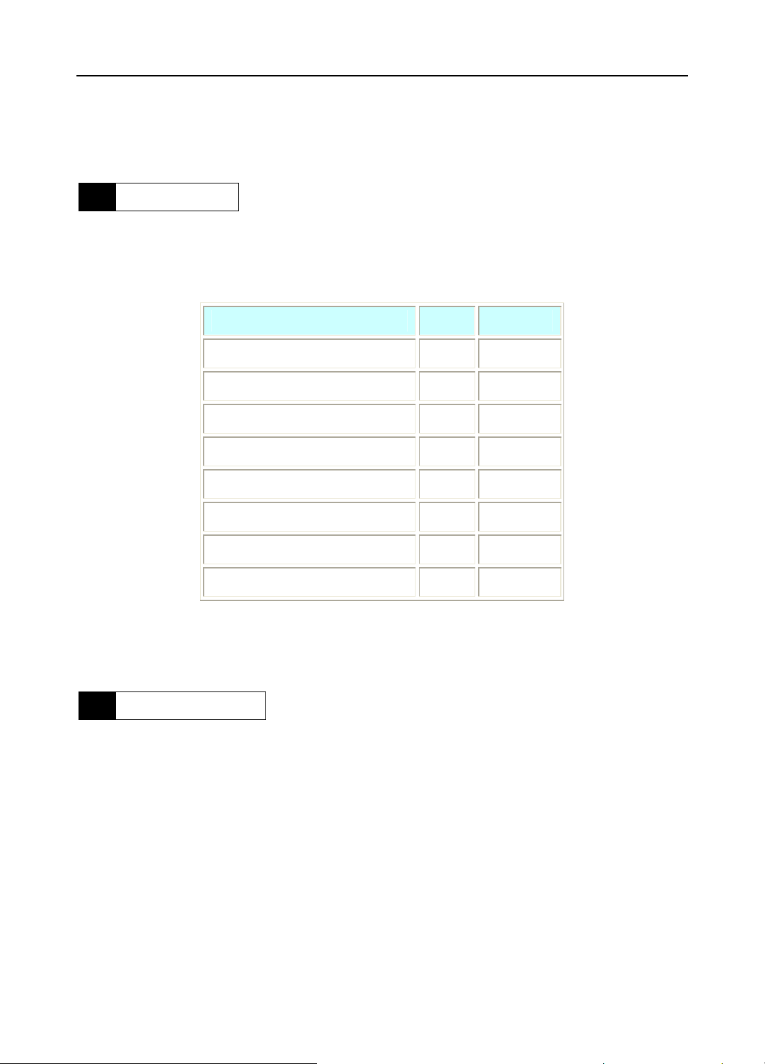
After unpacking the shipping container, please do following checking:
(1) Any signs of damage or scratching on the outlook of the products
(2) Table of contents:
DESCRIPTION QTY. REMARK
TH2820 LCR Meter 1
Power cable 1
TH26004 test cable 1
Fuse 2 1A
TH2820 LCR METER
Calibration report 1
QA Certificate 1
Warranty Certificate 1
User’s Manual 1
If any damages or incompleteness of contents are found when receiving the product,
please immediately contact our company or our dealer from whom you purchased the product.
2 Warranty
War rant y P e r i od:This product is warranted against defects in material and workmanship
for a period of two years from the date of shipment.
Warranty certificate should be presented for warranty service or repair. Our Company
provides lifetime service for our products.
The foregoing warranty shall not apply to defects resulting from improper or inadequate
maintenance by Buyer, Buyer-supplied software or interfacing, unauthorized modification or
misuse, operation outside of the environmental specifications for the product, or improper site
preparation or maintenance. In this case, buyer shall pay charges for shipping and repair.
24
 Loading...