

Tonghui Electronic TH9310 Series, TH9320 Series Operation Manual

◇1
TH9310/20 Series
AC/DC Withstanding Voltage/
Insulation Resistance Tester
Operation Manual
Tonghui Electronic Co.,Ltd.
www.tonghui.com.cn

◇2
Manual Printing History
The manual printing data and part number indicate its current edition. The
printing date changes when a new edition is printed. The manual part number
changes when extensive technical changes are incorporated.
TH9310/20 Series Operation Manual…………………………….2013.8

◇3
Content
Chapter 1 Setup ..................................................................................................................6
1.1 Unpacking .................................................................................................................................6
1.2 Precautions for Use .................................................................................................................6
1.3 Precautions for Moving............................................................................................................8
1.4 Checking Power Source and Fuse........................................................................................8
1.4.1 Toggle power line voltage ..........................................................................................................................8
1.4.2 Checking or replacing fuse........................................................................................................................8
1.5 Connecting the AC Power Cord.............................................................................................9
1.6 Grounding..................................................................................................................................9
1.7 Checking Operations .............................................................................................................10
1.8 Other Specifications...............................................................................................................11
Chapter 2 Precautions on Handling.............................................................................12
2.1 Prohibited Operations............................................................................................................12
2.2 Action When in Emergency ..................................................................................................13
2.3 Precautions on Testing..........................................................................................................13
2.4 Warning for Residual High Voltages ...................................................................................14
2.5 Dangerous States of Failed Tester......................................................................................15
2.6 To Ensure Long-Term Use without Failures ......................................................................15
2.7 Daily Checking........................................................................................................................16
Chapter 3 Part names and Functions..........................................................................17
3.1 Front Panel..............................................................................................................................17
3.1.1 POWER...................................................................................................................................................17
3.1.2 START and STOP ...................................................................................................................................17
3.1.3 Band and Model ......................................................................................................................................17
3.1.4 USB Interface ..........................................................................................................................................17
3.1.5 Indicator...................................................................................................................................................17
3.1.6 FUNCTION ..............................................................................................................................................18
3.1.7 HV ...........................................................................................................................................................18
3.1.8 Output voltage HIGH terminal (HV).........................................................................................................18
3.1.9 Test low terminal, test current return terminal (LOW/RET)......................................................................18
3.1.10 Move key ...............................................................................................................................................18

◇4
3.1.11 Shortcut key...........................................................................................................................................18
3.1.12 COPY key..............................................................................................................................................18
3.1.13 LCD screen ...........................................................................................................................................18
3.2 Instruction of rear panel.........................................................................................................18
3.2.1 Fan ..........................................................................................................................................................19
3.2.2 Test low terminal, test current return terminal (optional) .........................................................................19
3.2.3 High voltage output terminal (optional)....................................................................................................19
3.2.4 Power jack: with fuse holder, switchable line voltage mode....................................................................19
3.2.5 Protective earth terminal .........................................................................................................................19
3.2.6 Mark ........................................................................................................................................................19
3.2.7 RS232C serial interface ..........................................................................................................................20
3.2.8 USB serial communication interface .......................................................................................................20
3.2.9 HANDLER interface ................................................................................................................................20
3.2.10 SIGNAL interface...................................................................................................................................20
3.3 Description ..............................................................................................................................20
Chapter 4 Basic operation..............................................................................................26
4.1 Interface structure overview .................................................................................................26
4.2 Instruction of panel function interface and parameter ......................................................27
4.2.1 SETUP ....................................................................................................................................................28
4.2.2 TEST (Take AC for example)...................................................................................................................29
4.2.3 SYSTEM..................................................................................................................................................30
4.2.4 FILE.........................................................................................................................................................32
4.3 Test item interface and parameter setup............................................................................33
4.3.1 AC withstanding voltage test parameter setup:..................................................................................... 33
4.3.2 DC withstanding voltage test parameter setup :......................................................................................34
4.3.4 Open and short detection (OS) parameter setup:................................................................................. 36
4.4 Test function theory and instruction ....................................................................................37
4.4.1 Start up test .............................................................................................................................................38
4.4.2 Test delay ................................................................................................................................................38
4.4.3 Test voltage rise.......................................................................................................................................38
4.4.4 DC RAMP................................................................................................................................................38
4.4.5 High-voltage test......................................................................................................................................38
4.4.6 Voltage fall...............................................................................................................................................39
4.4.7 Ground wire current detection function ...................................................................................................39
4.4.8 Current over limit and arc detection (ARC) function................................................................................39
4.4.9 Fail judgment...........................................................................................................................................40
4.4.10 Deal with test results .............................................................................................................................41
4.4.11 STOP.....................................................................................................................................................41

◇5
4.4.12 OFFSET ................................................................................................................................................41
4.5 Structure and Use of HANDLER and SIGNAL Interface Circuit......................................42
4.5.1 Control interface theory ...........................................................................................................................42
4.5.2 Control interface instruction.....................................................................................................................43
4.6 Other interface and function .................................................................................................43
4.7 Serial port commands instruction ........................................................................................44
4.7.1 SCPI commands .....................................................................................................................................44
4.7.2 DISPlay Subsystem Commands .............................................................................................................44
4.7.3 FUNCtion Subsystem Commands ..........................................................................................................45
4.7.4 FETCh Subsystem Commands...............................................................................................................64
4.7.5 SYSTem Subsystem Commands ............................................................................................................65
4.7.6 Other Commands ....................................................................................................................................71
Chapter 5 Appendix .........................................................................................................72
5.1 Model and Specification of TH9320 series/TH9310 series ........................................72

◇6
Chapter 1 Setup
This chapter describes the procedures from unpacking to installation to
operation checking.
1.1 Unpacking
Upon receiving the product, confirm that the necessary accessories are included and
have not been damaged in transit. Should any damage or shortage be found, please
contact TongHui distributor/agent.
Items Quantity
TH9310/20 1
TH90003R withstanding-voltage test leadwires 1
TH90003B withstanding-voltage ground leadwires 1
2.5A(220V-240V)/5A(100-120V)Time-lag Fuse
2 of each
AC Power cord 1
Operation Manual 1
Tes t R e port 1
Servicing card 1
Accessories ordered by customers 1
1.2 Precautions for Use
Be sure to observe the following precautions when using the tester.
Do not use the tester in a flammable atmosphere.
To prevent explosion or fire, do not use the tester near alcohol, thinner, or other
combustible materials, or in an atmosphere containing such vapors.
Avoid locations where the tester is exposed to high temperatures or
direct sunlight.
Do not locate the tester near a heater or in areas subject to drastic temperature
changes.
Operating temperature range: 5 °C to +35 °C
Storage temperature range: -20 °C to +60 °C

◇7
Avoid humid environments.
Do not locate the tester in a high-humidity environment—near a boiler, humidifier or
water supply.
Operating humidity range: 20% to 80% RH (no dew condensation permitted)
Storage humidity range: 90%RH or less (no dew condensation permitted)
Condensation may occur even within the operating humidity range. In that case, do not
start using the tester until the location is completely dry.
Do not place the tester in a corrosive atmosphere.
Do not install the tester in a corrosive atmosphere or one containing sulfuric acid mist or
the like. This may cause corrosion of various conductors and imperfect contact with
connectors, leading to malfunction and failure, or in the worst case, a fire.
Do not locate the tester in a dusty environment.
Dirt and dust in the tester may cause electrical shock or fire.
Do not use the tester where ventilation is poor.
This tester features a forced-air cooling system. Provide sufficient space for the air inlet
on the lateral side and the air outlet on the rear side to allow air to flow.
Do not place the tester on a tilted surface or in a location subject to
vibrations.
If placed on a non-level surface or in a location subject to vibration, the tester may fall,
resulting in damage and injury.
Do not use the tester in locations affected by strong magnetic or
electric fields.
Operation in a location subject to magnetic or electric fields may cause the tester to
malfunction, resulting in electrical shock or fire.
Do not use the tester in locations near a sensitive measuring
instrument or receiver.
Operation in a location subject, may cause such equipment may be affected by noise
generated by the tester.
At a test voltage exceeding 3 kV, corona discharge may be generated to produce
substantial amounts of RF broadband emissions between grips on the test leadwire. To
minimize this effect, secure a sufficient distance between alligator clips. In addition, keep
the alligator clips and test leadwire away from the surfaces of conductors (particularly
sharp metal ends).

◇8
1.3 Precautions for Moving
When moving the tester to the installation site or otherwise transporting it, take the
following precautions:
Before moving the tester, turn off the power switch.
Transporting the tester with its POWER switch on can lead to electric shock and
damage.
When moving the tester, Disconnect all wires from it.
Moving the tester without disconnecting the cables may result in breakage of the wire or
injury due to the tester tipping over.
1.4 Checking Power Source and Fuse
1.4.1 Toggle power line voltage
!
WARNING:This instrument is designed to operate from the overvoltage category II.
Do not operate it from the overvoltage category III or IV.
Before turning on the power, make sure of the identifying fuse and the source voltage
agree with the input voltage on the rear panel.
Allowable voltage range:
110V:AC(99V to121V AC)
220V:AC(198V to 242V AC)
Allowable frequency range: 47 Hz to 63 Hz
!
WARNING: To prevent malfunctions, be sure to operate within the above voltage
range.
1.4.2 Checking or replacing fuse
!
WARNING To prevent electric shock, before checking or replacing the fuse, be sure to
turn off the POWER switch and unplug the AC power cord.
Make sure that the fuse used conforms to the instrument specifications, including shape,
rating, and characteristics. Using a fuse with different rating or short-circuiting, the fuse
holder will damage the instrument.
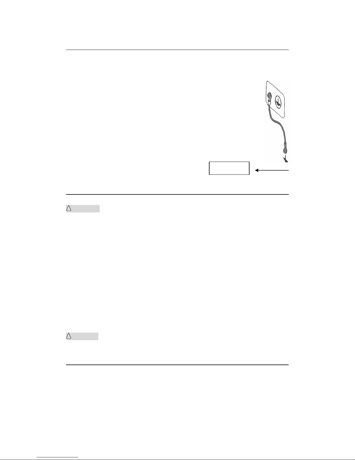
1. Turn off the POWER switch, and unplug the AC power cord.
◇9
2. On the rear panel, remove the fuse holder, by pushing it inward and unscrewing it
counterclockwise using a screwdriver.
3.The fuse holder has the feature of switching the power input range and it shall reveal
the POWER mark on the outer shell.
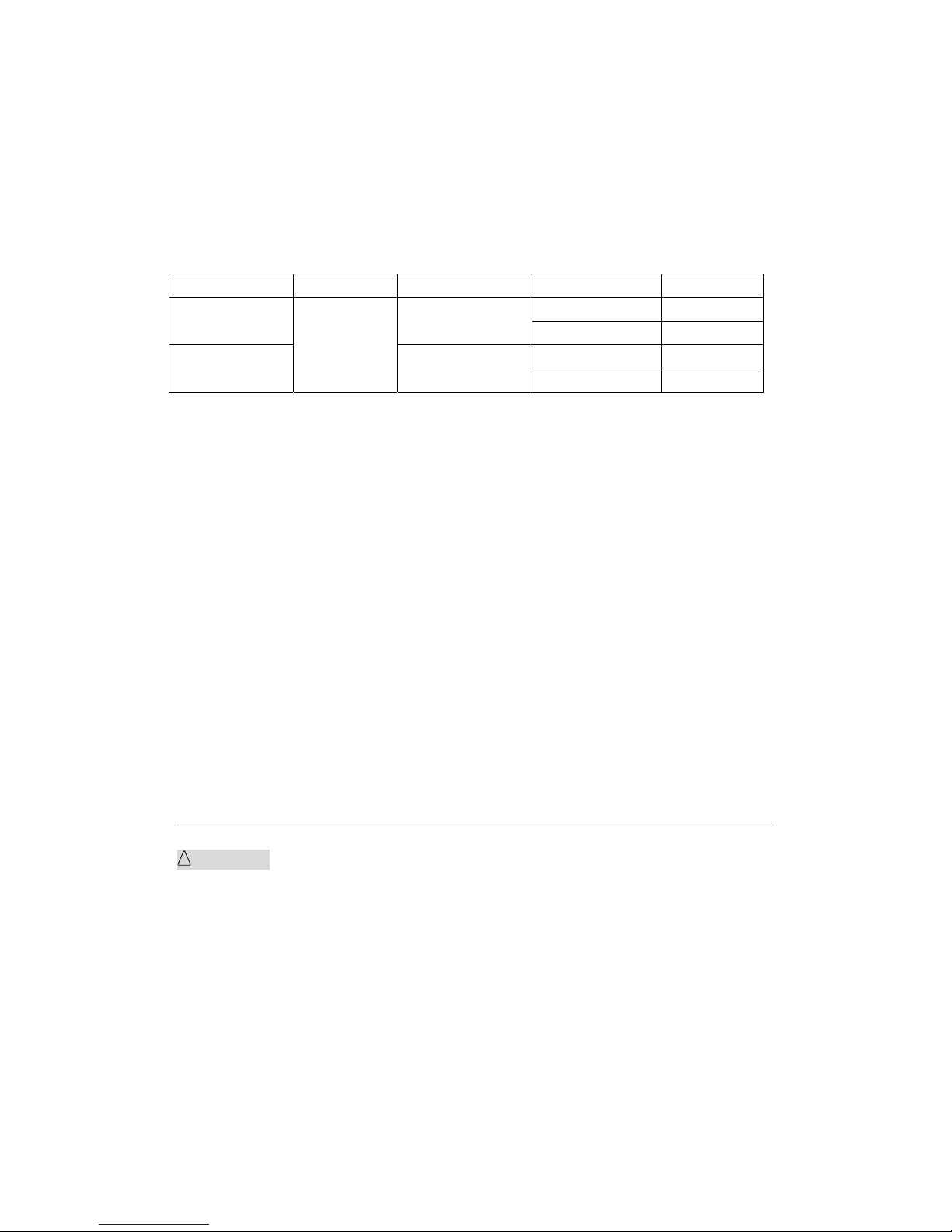
4. Check the fuse type and choose the fuse according to the following table. The fuse is
time lag fuse.
5. Reinstall the fuse holder.
Voltage range Frequency Fuse(Time-lag) Instrument series Rated Power
TH9320 400VA
110V 5A
TH9310 300VA
TH9320 400VA
220V
47-63Hz
2.5A
TH9310 300VA
1.5 Connecting the AC Power Cord
The power cord that is provided varies depending on the destination for the product at
the factory-shipment.
Do not use the AC power cord provided with the product as an AC power cord for
other instruments.
Connection procedure:
1. Confirm that the supply voltage is within the line voltage range of the tester.
2. Confirm the nominal value of the fuse and the line power are correctly selcected.
3. Confirm that the POWER switch on the tester is off.
4. Connect the AC power cord to the AC LINE connector on the rear panel.
5. Use the provided power code or power code that is selected by qualified personnel.
6. Plug in the AC power cord.
1.6 Grounding
!
WARNING: Be sure to connect the tester to an electrical ground (safety ground). If the
output to a conveyer or peripheral device that is connected to an earth ground or a
nearby commercial power line is short-circuited without grounding, the tester chassis is
charged to an excessively high voltage, resulting in extreme danger.
This tester is designed as a ClassⅡequipment (equipment protected against electric
shock with protective grounding in addition to basic insulation). Therefore, electric shock
◇10
may occur without proper grounding.
To ensure safety, be sure to ground the tester.
Choose either of the following two available methods of doing so:
1. Connect the AC power cord to a three-contact grounded electrical outlet.
2. Connect the protective conductor terminal on the rear panel to the earth
ground.
Have specialized engineers select, manufacture, and install cables.
To ensure secure connection, use proper tools.
1.7 Checking Operations
!
WARNING: Use the interlock jumper only to quickly cancel the protection status.
When using this tester in a cramped working space, make a box-like structure for the
DUT; when testing a complicated large-scale DUT, provide a cover or other means for
the DUT to prevent electric shock by cutting off the output when the cover is opened. It is
also recommended that an enclosure be provided around the operating area and that
output be cut off every time the door is opened.
Before turning on the power, confirm that the allowable voltage range indicated on the
power supply is the same as that indicated on the rear panel of the tester.
When the power is turned on, the tester lights all LEDs on the front panel and
self-diagnosis is started.
Before starting up the tester, confirm that all LEDs are on to ensure safety.
It is particularly dangerous to start a test when the DANGER lamp is broken.
Note that, in self-diagnosis, even when the DANGER lamp is lighting, no output or
voltage is being generated.
!
CAUTION: After turning off the POWER switch, wait several seconds before turning it
on. Turning the POWER switch on/off repeatedly with insufficient intervals may damage
the tester.
Earth

◇11
Checking procedure:
1. Confirm that the allowable voltage range indicated on the power supply is the same as
the input voltage range set by the fuse holder.
2. Confirm that the AC power cord is properly connected to the AC LINE connector on
the rear panel.
3. Plug in the AC power cord.
4. Turn on the POWER switch. Confirm that all LEDs on the front panel are lit. Following
the opening screen, display the ACW screen.
5. Following the opening screen, display the ACW screen and confirm that the tester is
kept in the READY status.
6.Turn on the POWER switch again.
Opening screen:
Tonghui
TH9320
HIPOT TESTER AC/DC/IR/OS
VERSION 1.0.6
2013.8.15
1.8 Other Specifications
1. Power: ≤500VA (TH9320/A/B)
≤400VA (TH9310/A/B)
2. Dimensions(W*H*D): 340mm*120mm*450mm;
3. Weight: approx. 15kg(TH9320/A/B); approx. 13kg(TH9310/A/B).
◇12
Chapter 2 Precautions on Handling
This chapter describes the precautions to be followed in the handling of this tester.
When using the tester, take utmost care to ensure safety.
!
WARNING :The tester derivers a 5 kV test voltage which can cause human injury or
death. When operating the tester, be extremely careful and observe the cautions,
warnings, and other instructions given in this chapter.
2.1 Prohibited Operations
Do not turn on/off the power repeatedly
After turning OFF the power switch, be sure to allow several seconds or more before turning it
ON again. Do not repeat turning ON/OFF the power switch rapidly. If you do this, the
protectors of the tester may not be able to render their protective functions properly. Do not
turn OFF the power switch when the tester is delivering its test voltage–you may do this only in
case of emergency.
Do not short the output to the earth ground
Pay attention so that the high test voltage line is not shorted to a nearby AC line or nearby
devices (such as conveyors) which are connected to an earth ground. If it is shorted, the tester
chassis can be charged up to the hazardous high voltage. Be sure to connect the protective
grounding terminal of the tester to an earth line. If this has been securely done, even when the
HIGH VOLTAGE terminal is shorted to the LOW terminal, the tester will not be damaged and
its chassis will not be charged up to the high voltage.
Be sure to use a dedicated tool when grounding the protective grounding terminal.
!
CAUTION: The term "AC line" here means the line on which the tester is operating. That is
the line to whose outlet the AC power cable of the tester is connected. It may be of a
commercial AC power line or of a private-generator AC power line.
Do not apply an External Voltage
Do not apply a voltage from any external device to the output terminals of the tester. The

◇13
analog voltmeter on the front panel cannot be used as stand-alone voltmeter. They may be
damaged if their output terminals are subject to an external voltage.
2.2 Action When in Emergency
In case of an emergency (such as electric shock hazard or burning of DUT), take the following
actions. You may do either (a) or (b) first. But be sure to do both.
1. Turn OFF the power switch of the tester.
2. Disconnect the AC power cord of the tester from the AC line receptacle.
2.3 Precautions on Testing
Wearing Insulation Gloves
When handling the tester, be sure to wear insulation gloves in order to protect yourself against
high voltages. If no insulation gloves are available on your market, please order Kikusui
distributor/agent for them.
Precautions for Pausing Tests
When changing test conditions, press the STOP switch once to take precautions. If you are not
going to resume the test soon or if you are leaving the Test area, be sure to turn-OFF the
POWER switch.
Items Charged Up to Dangerous High Voltages
When in test, the HV output, HV test leads, HV probes, DUT and output terminals and their
vicinities can be charged up to dangerous high voltages. Never touch them when in test.
!
WARNING: The vinyl sheaths of the alligator clips of the test leadwires which are supplied
accompanying the tester have no sufficient insulation for the high test voltages. Never touch
them when in test.
Matters to be Sure of After Turning-OFF Power
If you have to touch the DUT, test leadwires, probes, and/or output terminals and their
vicinities for re-connections or other reasons, be sure of the following two matters.
1. To confirm that the working condition is not in test mode.
2. The DANGER lamp has gone out.
Warnings for Remote Control
Be extremely careful when operating the tester in the remote control mode in which the
dangerous high test voltage is ON/OFF-controlled remotely. The operator cannot know the real

◇14
working condition of the instrument through the interface. Please pay special attention to
check the reliable connection of the remote control:
1. The “STOP” switch must be connected reliably. Press the “STOP” switch before changing
the DUT.
2. When testing in a working environment with a lot of people, remote control switch has the
“INTLOCK”switch and HV lamp. Disconnect the “INTLOCK” switch before changing the
DUT.
Provide means to assure that none can touch the DUT, test leadwires, probes, output
terminals and their vicinities when the test voltage is being delivered.
2.4 Warning for Residual High Voltages
!
WARNING: In DC withstanding voltage testing and insulation resistance testing, the test lead
wire, test probe, and DUT are charged to a high voltage. The tester is equipped with a
discharge circuit, but some time is nonetheless required to discharge them after the output is
cut off. There is a danger of electric shock during discharge. To avoid electric shock, take the
utmost care to ensure that the DUT, test lead wire, probe, and highly charged parts around the
output terminal are not touched. If it is necessary to touch them, be sure to confirm the
DANGER lamp has gone out.
As soon as the output is cut off, the tester’s discharge circuit starts forced discharging. Do not
disconnect the DUT during a test or prior to completion of discharging.
Under normal circumstances, it can be guaranteed that the test loop voltage is within the safe
voltage range when finishing discharging. When the capacitance of the DUT is too large or the
structure of the DUT is special, it may leads to incomplete discharge. In order to ensure
complete discharge, test method must be changed by technical personnel.
Discharge time:
Computational formula of discharge time: t = -ln(30 / U)×R×C
t: discharge time
30: discharge residue safty voltage 30V
U: test set voltage
R: discharge impedance of the DUT, the discharge impedance of the instrument is approx. 10k
C: capacitance of the DUT
In general, only DC high voltage test needs discharge and the length of the discharge time
varies according to the properties of the DUT.
If the test terminated normally, the voltage will drop to zero according to the voltage fall time. If
the test failed, discharge of the DUT is conducted by the transformer secondary
winding(resistance of approximately 10k). Approximately 0.05s are required for 1uF capacitor
with high voltage of 6000V to discharge to 30V. The fixed discharge time of the instrument is
◇15
0.2s, which ensures complete discharge of the device.
2.5 Dangerous States of Failed Tester
Typical possible dangerous states of the tester are as shown below and in which cases the
most dangerous situation that “the high test voltage remains delivered and the instrument
get out of control” may occur. When this situation has occurred,
1. Immediately turn OFF the power switch and disconnect the AC power cable from the AC
line receptacle.
2. Immediately keep far away from the instrument and confirm no risk of the test circuit by the
technical personnel; or keep the instrument still for more than one hour and confirm no
output voltage in the test terminal.
3. Remove the relevant connecting lines and send the instrument back to us for
maintenance.
!
WARNING: Keep away from the instrument after turning off the power and prevent other
people from approaching. Do not immediately disassemble the test circuit. Immediately call our
distributor or agent. High voltage may remain in the interior of the instrument. It is hazardous
for an unqualified person to attempt to troubleshoot any tester problem.
2.6 To Ensure Long-Term Use without Failures
The withstanding voltage-generating block of the tester is designed to release half the rated
amount of heat, in consideration of the size, weight, cost, and other factors of the tester. The
tester must therefore be used within the ranges specified below. If you deviate from these
ranges, the output block may be heated to excess, activating the internal protection circuit.
Should this happen, wait until the temperature returns to the normal level.
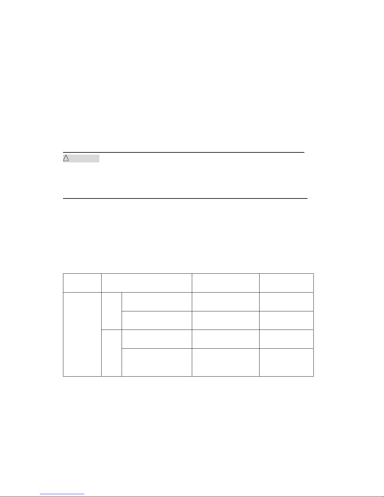
Output requirements for withstanding voltage testing
Ambient
temperature
Upper current Pause Time Output time
>12mA (TH9320/A/B)
>6mA (TH9310/A/B)
At least as long as the
output time
Maximum of 1
minute
AC
<8mA (TH9320/A/B)
<4m (TH9310/A/B)
Not necessary
Continuous output
possible
>6mA (TH9320/A)
>3mA (TH9310/A)
At least as long as the
output time
Maximum of 1
minute
T≤40℃
DC
<4mA (TH9320/A)
<2mA (TH9310/A)
At least as long as the
charging wait time
(WAIT TIME)
Continuous output
possible
Note: Test time <= Output time <= voltage rise time + test time + voltage fall time

◇16
2.7 Daily Checking
To avoid accidents, confirm at least the following before starting operation:
1. The input source complies with the standard and the tester power configuration is correct.
2. The tester is connected to an earth ground.
3. The coating of the high-voltage test lead wire is free from cracks, fissures, and breakage.
4. Without connecting the test lines, the instrument can finish the test successfully when
starting test by default.
5. The tester generates FAIL signal when the ends of the low-voltage test lead wire and
high-voltage test lead wire are short-circuited.
◇17
Chapter 3 Part names and Functions
This chapter describes the names and functions of components such as switches, displays,
and connectors on the front and rear panels.
3.1 Front Panel
Figure 3-1 gives a brief description of the front panel for TH9310/20 series.
HV
RTN/LOW
OUTPUT
!
HIGH VOLT
MAX 5kV AC
START
STOP
POWER
FAIL PASS
SETUP
SYSTEM FILE
COPY
TEST
1
2
13
12
11
10
8
7
6
9
543
Figure 3-1
3.1.1 POWER
Power switch. Operators should check the power types and whether the test line
connections are normal.
3.1.2 START and STOP
START (square): Start up the instrument, once test starts, “TEST” will be displayed at the left
corner of the screen, TEST indicator lights.
STOP (circle): Stop key, used to cancel the test, or PASS, FAIL status.
3.1.3 Band and Model
Band and model.
3.1.4 USB Interface
Externally connect to USB storage.
3.1.5 Indicator
● FAIL
When the test data exceeds the set data in test, the instrument will lights in FAIL.
● PASS
When the test data does not exceed the set data after the test, the instrument will lights in
PASS.

◇18
When time function is off (TIMER OFF), there is no PASS judge. The test can be finished only
by pressing the ‘STOP’ key.
3.1.6 FUNCTION
Select mode, system and interface.
● TEST
Press the key and the corresponding key lights, the instrument is ready to test.
● SETUP
Press the key and the corresponding key lights, the instrument enters parameter setting;
● SYSTEM
Press the key and the corresponding key lights, the system setting interface will be displayed;
● FILE
Press the key and the corresponding key lights, the file operation interface will be displayed;
3.1.7 HV
DANGER!!It lights in test, indicating the test is underway.
3.1.8 Output voltage HIGH terminal (HV)
High voltage output of the high voltage test interface.
3.1.9 Test low terminal, test current return terminal (LOW/RET)
Voltage output terminal and current sampling terminal of the test.
3.1.10 Move key
It is used for moving cursor on the screen.
3.1.11 Shortcut key
F1-F5, corresponding with the function operation area on the right of the LCD.
3.1.12 COPY key
COPY key can copy the screen pictures to the USB storage. The USB starage should be
inserted into the USB jack on the front panel in advance.
3.1.13 LCD screen
480*272 TFT dot- matrix LCD screen, display setting and test interface, etc.
3.2 Instruction of rear panel
Figure 3-2 gives a brief description of the front panel for TH9310/20 series.

◇19
HV OUTPUT
110V/220V~50/60Hz
HANDLE RS-232C
SIGNAL
USB
RTN/LOW
WARNING:
FOR CONTINUED PROTECTION A GAINST FIRE HAZARD,
REPLACE ONLY WITH THE SAM E TYPE AND RATING OF FUSE AS
SPECIFIED FOR THE LINE VOL TAGE BEING UTILIZED.
CAUTION:NO OPERATOR SERVICEABLE PARTS INSIDE
REFER SERVICING TO QUALIT IFIED PERSONNEL.
!
!
HIGH VOLTAGE
MAX:5kV AC
1 2 3 4 5
6789
10
Figure 3-2
3.2.1 Fan
Power amplifier circuit radiator.
3.2.2 Test low terminal, test current return terminal (optional)
Stand-by test low terminal of high voltage test interface.
3.2.3 High voltage output terminal (optional)
Stand-by high voltage output terminal of high voltage test interface.
3.2.4 Power jack: with fuse holder, switchable line voltage mode
Be used to input AC power. Please use the voltage within the specified input voltage range and
please use the attached power line with fuse. Change the fuse according to input power.
Please choose different installation position according to different input power type. Please pay
attention to the visible identification on the outer shell of the fuse holder when installing.
NOTE: The instrument supports 110 and 220 line voltage modes only. Other modes are
not connected in the interior of the instrument.
3.2.5 Protective earth terminal
Be used to connect instrument to ground.
NOTE: The three-pin power jack of the instrument can not guarantee reliable connection
to the ground. The protective earth terminal must be used to connect the instrument to
grounding bar.
3.2.6 Mark
This mark describes the serial number of the instrument.

◇20
3.2.7 RS232C serial interface
Serial communication, realize the communication with the computer.
3.2.8 USB serial communication interface
Realize the communication with the computer. Through this interface, the computer can control
the instrument by using the control instruction set.
3.2.9 HANDLER interface
Compared to PLC interface, the HANDLER interface has no INTERLOCK function in interface
signal. It is more convenient than PLC interface to use 9 core model D jack to output. It is
appropriate for the connection of general control circuit for multiple instruments.
TEST:Output synchronized-signal control when high voltage output is started.
START:Input the starting signal for starting high voltage output, corresponding to START
signal on the front panel.
RESET:Input the reset signal for stopping high voltage output, corresponding to STOP
signal on the front panel.
PASS :The output pass signal of the instrument, corresponding to PASS instruction on the
front panel.
FAIL:The output fail signal of the instrument, corresponding to FAIL instruction on the
front panel.
3.2.10 SIGNAL interface
It is the interface for online protection and interior 24V power output.
INTERLOCK:(COM(5) S+ -- (6) COM) valid in SHORT. It is the online locking signal of
the instrument, if off, starting output is not allowed.
DC 24V Power: (COM(1,2) 24V – (3,4) GND). It is used for requirement of indicator light
and other control power supply.
3.3 Description
TH9320 Provide 5kVAC/20mA withstanding voltage, 6kVDC/10mA withstanding voltage
and insulation resistance test.
TH9320A Provide 5kVAC/20mA withstanding voltage, 6kVDC/10mA withstanding voltage
test.
TH9320B Provide 5kVAC/20mA withstanding voltage test.
TH9310 Provide 5kVAC/10mA withstanding voltage, 6kVDC/5mA withstanding voltage and
insulation resistance test.
TH9310A Provide 5kVAC/10mA withstanding voltage, 6kVDC/5mA withstanding voltage
test.
TH9310B Provide 5kVAC/10mA withstanding voltage test.

◇21
The principle structure of the instrument: In high voltage module, there is a DA
standard, controllable forcing function generator, AB power amplifier, 40~600Hz high voltage
boost transformer and output voltage closed-loop control.
DA standard: ensure controllable output voltage amplitude.
Controllable forcing function generator: In AC output, set the operation in 50 or 60Hz,not
being limited by line voltage.
Linear power amplifier: low distortion of the voltage waveform with easy control and high
reliability.
40~600Hz high voltage boost transformer: to DC and insulation resistance test, the test
instrument uses 600Hz AC to form DC voltage to be the power, which can assure the DC
power ripple is far less than the formal withstanding voltage tester.
Output voltage closed-loop control: ensure small load regulation and reliable test data.
Software of the instrument: multiparameter continuous test and multiple upper
computer control function.
TH9310/20 series not only can perform the independent AC withstanding test, DC
withstanding voltage test, insulation resistance test, but also multi-item test via the setting of
test programme.
TH9310/20 series all allocate HANDLER, RS-232C and USB, thus the instrument can
adapt to the auto test system of different required safety and reliability.
Feature:
■ 4 test functions—AC withstanding voltage test, DC withstanding voltage test,
insulation resistance test, open and short detection.
TH9310, TH9320 provide AC/DC withstanding voltage test and insulation resistance test.
TH9310A, TH9320A provide AC/DC withstanding voltage test.
TH9310B, TH9320B provide AC withstanding voltage test.
All the instruments have the open and short detection function.
Once connected with load, the tester can perform different tests continually.
■ 2 different test power selection
In TH9320 series high voltage module, there is a AB power amplifier circuit and a 100VA
high voltage transformer, which can realize the output of 5kV/20mA (AC) and the output of
5kV/10mA (DC). The distortion of the waveform is less than 3%.
In TH9310 series high voltage module, there is a AB power amplifier circuit and a 50VA
high voltage transformer, which can realize the output of 5kV/10mA and the output of
5kV/5mA (DC). The distortion of the waveform is less than 3%.
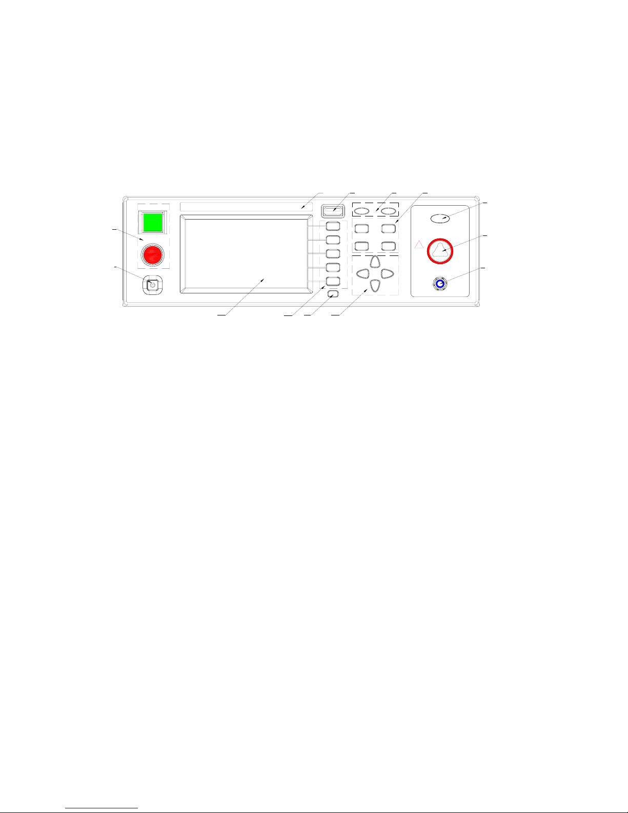
If continuous current output is set, in order to guarantee the reliability of the instrument, the
maximum output time is 60 seconds when the output is more than 60% of the rated output
current. If the output is within 60%~40% of the rated output current, the continuous
working hours should be limited. If the output is less than 40% of the rated output current,
◇22
it can ensure continuous working.
Figure 3-3 AC voltage load regulation
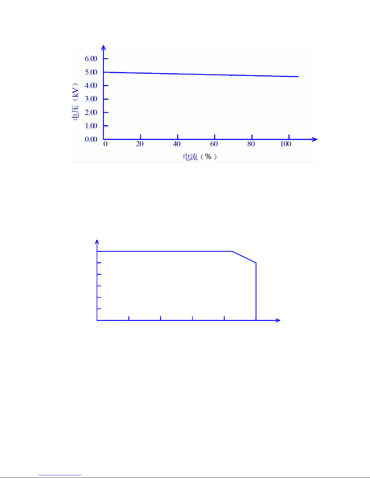
DC withstanding voltage test 5kV/10mA(TH9320/A)5kV/5mA(TH9310/A)
TH9310/20 series can provide DC withstanding voltage test of wide voltage range (Max.
output DC is 6kV). The automatic voltage regulation and voltage load regulation of
600Hz frequency hardware is less than 1%+10V.
0.0 0
1.0 0
2.0 0
3.0 0
4.0 0
5.0 0
电压(
kV
)
6.0 0
0246810
电流(
m
A
)
Figure 3-4 TH9320/A DC voltage output range
■ Insulation resistance test 0.050kV to 1.000kV(resolution of 1V)/0.1MΩ to 10.0GΩ
(Max. rated current of TH9320 is 10mA and max. rated current of TH9310 is 5mA)

◇23
Insulation resistance test range:
When the voltage is less than 500V: 0.1MΩ to 1GΩ with accuracy of ±[10% reading +5
digits].
When the voltage is greater than 500V: 0.1MΩ to 100MΩ with accuracy of [5% reading +5
digits], 100MΩ to 1GΩ with accuracy of [10% reading +5 digits].
■ Open and short detection: judge the reliability of the DUT before starting the high
voltage to ensure the accuracy and safety of high voltage test.
Open and short detection can judge the distribution impedance current of more than 100PF.
When the current is less than this value, the current acquisition circuit resolution of the
instrument can not distinguish the connection of open circuit and the test component
accurately.
■ RS-232C interface as the standard
Except power switch, key lock and execution (auto), other functions can be controlled
remotely. In DC withstanding voltage test, AC withstanding voltage test and insulation
resistance test, judge and time can be controlled remotely. The test result can also be read
via remote control. USB and RS-232C interface provides a stable and united standard test
interface for PC or other devices.
■ HANDLER and SIGNAL interfaces bring convenience for the connection and
control.
HANDLER interface can input START and STOP signals and output TEST, PA SS and
FAIL signals. Connecting with a footswitch, they can construct a foot-control device; while
connecting with simple test fixtures, they can realize safety interlock, air controls, test
indication, etc.
SIGNAL interface can input INTERLOCK signal and provide 24V, 1A power output. It is
convenient for control and connection.
■ USB interface for backup
Through the USB interface equipped by all testers, tester programmed test programmes
and customer’s measuring file can be saved to or recalled from an external U disk, which is
convenient to set, use and file a batch of testers.
■ Waiting time setup function
The instrument can set the test waiting time from 0.1s to 999.9s by a resolution of 0.1s. In
this period, the tester will output TEST control signals. They are used to control external
devices and ensure a reliable connection. After that high voltage measurement will be
enabled.
 Loading...