

Page 1

TH9010 Series
Multi-channel Hipot Tester
Operation Manual
Tonghui Electronic Co.,Ltd.
www.tonghui.com.cn
◇1
Page 2

Content
Chapter 1 Unpacking and Installing ......................................................................................................... 5
1.1 Precautions for Use..............................................................................................................................................5
1.2 Precautions when moving ....................................................................................................................................5
1.3 Connecting AC Power Cables .............................................................................................................................6
1.4 Grounding ............................................................................................................................................................6
1.5 Operation Check ..................................................................................................................................................6
1.6 Other Characteristics ...........................................................................................................................................7
Chapter 2 Precautions on Handling .......................................................................................................... 8
2.1 Prohibited Operation Behavior .....................................................................................................................8
2.2 Actions When in Emergency ........................................................................................................................8
2.3 Precautions in Testing ...................................................................................................................................9
2.4 High Voltage Test Warning ...........................................................................................................................9
2.5 Handling for Dangerous State of Faulty Tester ........................................................................................... 10
2.6 Conditions for ensuring long-time trouble-free working ............................................................................ 11
2.7 Daily inspection .......................................................................................................................................... 11
Chapter 3 Panel Description .................................................................................................................... 12
3.1 Front Panel ........................................................................................................................................................ 12
3.1.1 USB Interface ................................................................................................................................................................... 12
3.1.2 Start Button ...................................................................................................................................................................... 12
3.1.3 Stop Button ...................................................................................................................................................................... 12
3.1.4 POWER ........................................................................................................................................................................... 12
3.1.5 LCD Display .................................................................................................................................................................... 12
3.1.6 Shortcut Function Key ....................................................................................................................................................... 12
3.1.7 File Function Key ............................................................................................................................................................. 13
3.1.8 Numeric keypad ................................................................................................................................................................ 13
3.1.9 Indicator Area ................................................................................................................................................................... 13
3.1.10 High voltage indication and Work instruction ...................................................................................................................... 13
3.1.11 Cursor control switch ....................................................................................................................................................... 13
3.1.12 Code switch and knob ...................................................................................................................................................... 13
3.1.13 Test function area (FUNCTION) ....................................................................................................................................... 13
3.1.14 Copy ............................................................................................................................................................................. 14
3.1.15 Instrument Model Label ................................................................................................................................................... 14
3.2 Rear Panel.......................................................................................................................................................... 14
3.2.1 Product Name Plate ........................................................................................................................................................... 14
3.2.2 Test unit output module...................................................................................................................................................... 14
3.2.3 Test low terminal, test current return terminal (one per test unit) ............................................................................................. 14
3.2.4 High voltage output terminal (one per test unit) .................................................................................................................... 15
3.2.5 Power socket: self-contained fuse box ................................................................................................................................. 15
3.2.6 Protective ground terminal ................................................................................................................................ ................. 15
3.2.7 LAN Interface .................................................................................................................................................................. 15
3.2.8 RS232C serial interface ..................................................................................................................................................... 15
◇2
Page 3

3.2.9 USB serial communication interface .................................................................................................................................... 15
3.2.10 HANDLER interface ....................................................................................................................................................... 15
3.2.11 SINGLE interface ............................................................................................................................................................ 15
3.3 Multi-unit scanner description ........................................................................................................................... 15
3.3.1 EXTENSION: serial number of the current controller .......................................................................................................... 16
3.3.2 UNIT n: Unit n ................................................................................................................................................................. 16
3.3.3 CH n: scan channel n ......................................................................................................................................................... 16
3.3.4 SIGNAL IN/OUT: Control signal input (female) / output (male) ............................................................................................. 17
3.3.5 UNIT n INPUT/OUTPUT: Unit n input / output.................................................................................................................... 17
3.3.6 Power Input ...................................................................................................................................................................... 17
3.4 Instrument Performance Overview .................................................................................................................... 17
Chapter 4 Basic operation ........................................................................................................................ 22
4.1 Interface structure overview .............................................................................................................................. 22
4.2 Panel function interface and parameter description ................................................................ ........................... 23
4.2.1 Test Interface .................................................................................................................................................................... 24
4.2.2 Setup Interface.................................................................................................................................................................. 24
4.2.3 System Interface ................................ ................................................................................................ ............................... 25
4.2.4 FILE storage interface ....................................................................................................................................................... 29
4.3 Test project interface and parameter description ............................................................................................... 30
4.3.1 AC withstanding voltage test parameter setting ..................................................................................................................... 30
4.3.2 DC withstanding voltage test parameter setting ..................................................................................................................... 31
4.3.3 IR Insulation resistance test parameter setting ....................................................................................................................... 32
4.3.4 OS circuit test parameter setting .......................................................................................................................................... 33
4.3.5 S.CK Single-ended contact check parameter setting............................................................................................................... 35
4.3.6 D.CK Double-ended contact check parameter setting ............................................................................................................. 36
4.4 Test function principle and instructions for use................................................................................................. 36
4.4.1 Start Test .......................................................................................................................................................................... 38
4.4.2 Test Delay ................................ ................................................................................................................................ ........ 38
4.4.3 Voltage Rise ..................................................................................................................................................................... 38
4.4.4 DC boost decision ............................................................................................................................................................. 38
4.4.5 High Voltage Test .............................................................................................................................................................. 38
4.4.6 Test Voltage Fall ............................................................................................................................................................... 38
4.4.7 Ground Current Detection Function ..................................................................................................................................... 38
4.4.8 Current Overrun and Arc Detection (ARC) Function ............................................................................................................. 39
4.4.9 Failure Judgment .............................................................................................................................................................. 40
4.4.10 Test Result Processing ..................................................................................................................................................... 40
4.4.11 STOP (Stop Measuring) ................................................................................................................................................... 40
4.4.12 OFFSET (The base is cleared) .......................................................................................................................................... 40
4.5 SCAN multi-cell multi-channel scanning controller structure and use ............................................................. 41
4.5.1 After adding multiple scan channels, the instrument will add SCAN (multiple) parameters ......................................................... 41
4.5.2 Structural principle ............................................................................................................................................................ 42
4.6 Structure and Use of HANDLER and SINGNAL Interface Circuit .................................................................. 42
4.6.1 Control Interface Theory .................................................................................................................................................... 42
4.6.2 HANDLER Control Interface Main Signal Timing Description ............................................................................................... 43
4.7 File Storage Other interfaces and functions of the instrument .......................................................................... 44
◇3
Page 4

Chapter 5 Serial Port Commands Instruction ....................................................................................... 45
5.1 DISPlay Subsystem Commands ........................................................................................................................ 45
5.2 MMEM Subsystem Commands................................................................................................ ......................... 45
5.3 FUNCtion Subsystem Commands ..................................................................................................................... 46
5.3.1 FUNCtion test, Stop instruction .......................................................................................................................................... 46
5.3.2 FUNCtion File Editing Function Commands ........................................................................................................................ 46
5.3.3 FUNCtion Test Function, Test Parameter Commands ............................................................................................................. 46
5.3.4 Specific Examples of Command Data Format ....................................................................................................................... 47
5.4 SYSTem Subsystem Commands ....................................................................................................................... 54
5.5 Other Commands ............................................................................................................................................... 56
Chapter 6 Appendix .................................................................................................................................. 58
◇4
Page 5

Chapter 1 Unpacking and Installing
This chapter tells some of the check points that must be performed after you receive the instrument
and things you must know before installing the instrument.
1.1 Precautions for Use
Be sure to follow the rules below when using the instrument:
Do not use the instrument in flammable air
To prevent burning or explosion, do not use the instrument near alcohol, thinner and other
flammable materials, or in air with high concentrations of these gases.
Avoid exposing the instrument to high temperatures and direct sunlight
Do not place the instrument where it is hot or where the temperature changes drastically.
Operating temperature range: 5℃ to +35℃
Storage temperature range: -20℃ to +60℃
Avoid wet environment
Do not place the instrument in a boiler, humidifier or high humidity environment with water.
Operating humidity range: 20% to 80%RH (dew condensation is not allowed)
Storage humidity range: <90%RH (dew condensation is not allowed)
Water condensation can cause the circuit to malfunction. The instrument can only be used when the
environment is completely dry.
Do not place the instrument in an environment with corrosive gas or dust
Do not use the instrument in an environment where corrosive gases such as sulfuric acid, fog, dirt
and dust or the like are present. This can corrode wires, connectors, and create hidden dangers or
connection defects that can cause malfunctions, failures, and even fires.
Do not use the instrument in a poorly ventilated area
The instrument has a forced air cooling system. Please allow enough space for the side and rear air
vents to ensure air circulation.
Do not use the instrument on a sloping surface or in a rocking place
If the instrument is placed on a non-horizontal surface or shaken, the instrument may slip and
damage the instrument.
Do not use the instrument where there is a strong magnetic field or electric field effect
Use the instrument where there is a strong magnetic field or electric field. Electromagnetic pulses
can cause a malfunction in the instrument.
Do not use the instrument near sensitive measuring instrument or receiver
Operation in a location subject, may cause such equipment be affected by noise generated by the tester.
At a test voltage exceeding 3 kV, corona discharge may be generated to produce substantial amounts
of RF broadband emissions between grips on the test lead wire. To minimize this effect, secure a
sufficient distance between alligator clips. In addition, keep the alligator clips and test lead wire away
from the surfaces of conductors (particularly sharp metal ends).
1.2 Precautions when moving
When moving or transporting the instrument, be aware of the following precautions:
Turn off the power switch before moving
Moving with the power switch on will cause electric shock and damage.
◇5
Page 6
Disconnect all cables before moving
!
!
Safe
ground
Moving the instrument without disconnecting the cable may result in damage to the cable or drop the
instrument during handling it.
1.3 Connecting AC Power Cables
The power cord is supplied by Tonghui along with the instrument. Do not use an AC power cord that
is not included with the instrument.
Connection order:
1. Make sure the power supply is within the power cord range of the instrument.
2. Determine the nominal value of the instrument fuse, the fuse box is installed in the correct
position (power supply)
3. Make sure the instrument's power switch is off
4. AC power cord is connected to the AC LINE (AC power cable) end of rear panel.
5. Please use the supplied AC power cord, or the AC power cord selected by the qualified
professionals
6. Plug in an AC outlet
1.4 Grounding
Warning
Please make sure to connect the instrument to an electrical ground (safety ground, earth).
If the grounding of the power outlet is not connected to the peripherals or the ground of nearby
commercial wires, the instrument is not directly connected to the earth, and the chassis of the instrument
is charged with an excessively high voltage, which is very dangerous.
The instrument is a Class II device (the device is protected from electric shock in addition to the basic
insulation). However, there is still the possibility of electric shock if there is no proper grounding.
----------------------------------------------------------------------------------------------------------------------
To ensure safety, it is important to ensure that the instrument is grounded.
Select at least one of the following two available methods to ground:
1. The power cord is connected to a single-phase, three-wire power outlet. Make sure that
the socket’s ground wire is securely connected to the ground.
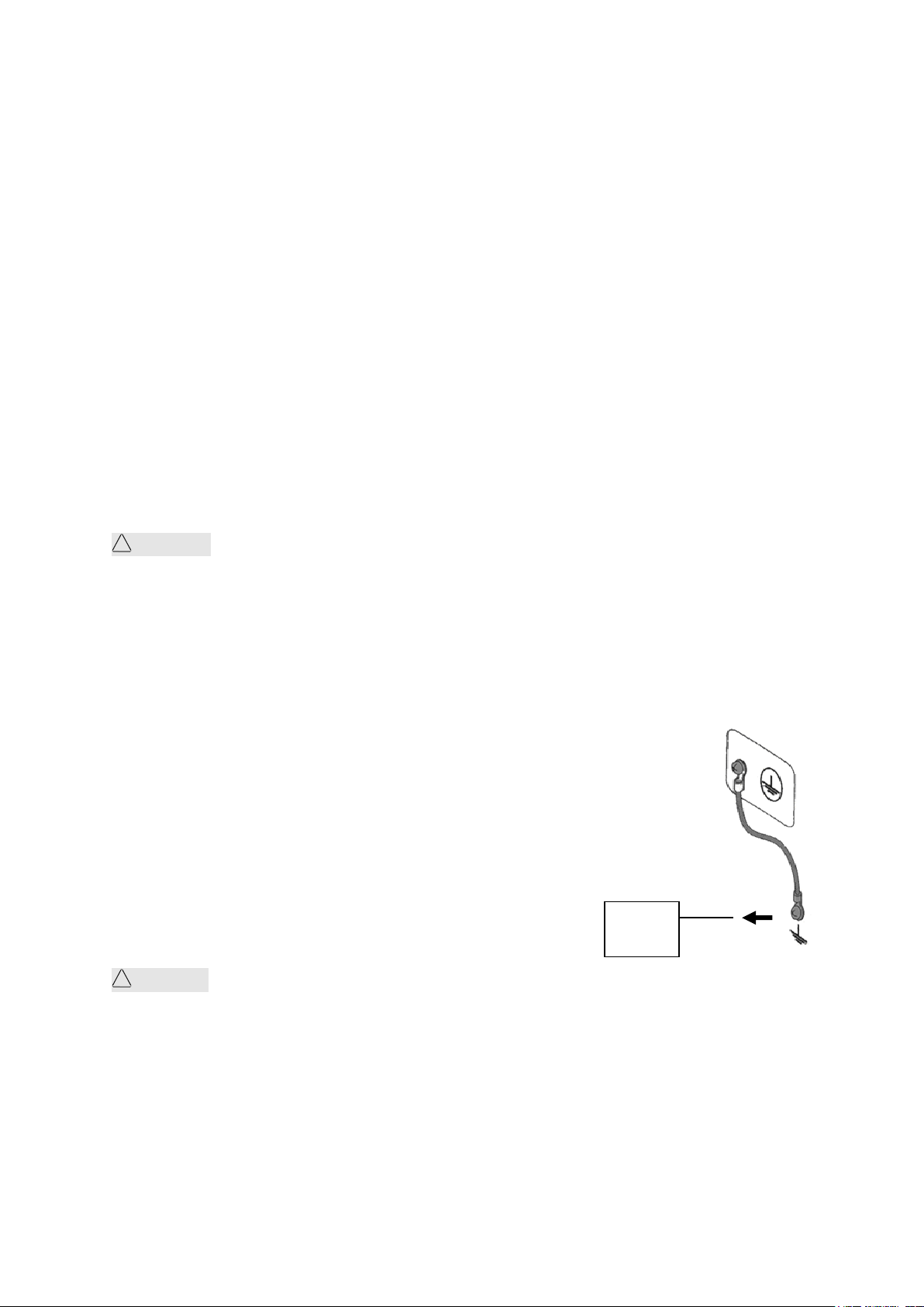
2. Connect the protective terminal of the rear panel to the ground through a grounding bar
(a copper wire or copper bar with a reliable connection to the ground which a production
line is equipped). Have a dedicated engineer select, make, and install the ground cable.
Ensure that the ground connection is correct and reliable.
1.5 Operation Check
Warning: During the normal operation, please use INTERLOCK to ensure the safety.
When using this tester in a cramped working space, make a box-like structure for the DUT; when
testing a complicated large-scale DUT: provide a cover or other means for the DUT to prevent electric
shock, cutting off the output when the cover is opened. It is also recommended that an enclosure be
provided around the operating area and that output be cut off every time the door is opened, to keep
the workplace safe and secure.
When the power switch is turned on, all the lights on the front panel lit on and begins a self-check to
make sure all indicators are working to ensure safety. It is particularly dangerous to conduct testing
when the DANGER indicator (high voltage hazard during testing) is damaged.
◇6
Page 7
!
Be Careful:After turning off the power switch, wait a few seconds after turning it on again.
Tonghui
Share The Future Technology
TH9010
Parallel Multi-Unit Hipot Tester
VERSION :1.0.9 Copyright(c)2017
http//www.tonghui.com.cn
Changzhou Tonghui Electronic Co . , Ltd.
Input Voltage
Frequency Range
Fuse (Slow Melting)
Rated Power
90V-240V
47-63Hz
15A
1200VA
Repeated on/off power supplies that do not have sufficient time intervals are detrimental to the
instrument.
Checking Order
1. Make sure that the allowable range of the supply voltage is the same as the input voltage
range set by the fuse box.
2. Make sure that the AC power cord is connected to the AC LINE end of the rear panel.
3. Plug the power cord into an AC outlet
4. Turn on the power switch and make sure that the indicators on the front panel are fully lit
on and the panel displays the startup screen.
5. The following screen display the AC withstand voltage test (AC) parameter interface of
(SETUP) interface
6. Turn off the power switch
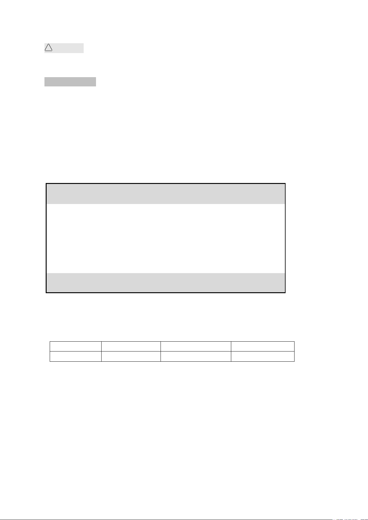
Start Up Screen:
1.6 Other Characteristics
(1)Power consumption: power consumption < 1000VA
(2) Dimensions (W*H*D): 430mm*175mm*630mm;
(3) Weight: about 35kg.
◇7
Page 8
Chapter 2 Precautions on Handling
!
This chapter describes the precautions to be followed in the handling of this tester. When using the
tester, take utmost care to ensure safety.
WARNING: The tester derives a 5 KV test high voltage, care must be taken when operating the
instrument and follow the cautions, warnings, and other instructions given in this chapter.
Keep them in mind to avoid accidents.
2.1 Prohibited Operation Behavior
Please do not turn on/off the power repeatedly.
After turning OFF the power switch, be sure to allow several seconds or more before turning it
ON again. Do not turn on/off power switch repeatedly, if you do this, the protectors of the
tester may not be able to render their protective functions properly. Do not turn OFF the power
switch when the tester is delivering test voltage, you may do this only in case of emergency.
Do not short the output terminal to the earth ground
Be careful not to short-circuit the high-voltage test leads of the instrument with nearby AC
LINE (AC power cord) or other nearby equipment (such as transmission equipment). If it is
shorted, the chassis of the instrument will be filled with dangerous high voltages.
Make sure that the protective ground terminal is connected with the ground wire, by doing so,
even if the HIGH VOLTAGE terminal is short-circuited to the ground, the instrument chassis
will not be charged with high voltage and there is no danger.
Please make sure to connect the protective ground terminal with the ground wire in correct and
reliable way, for details, please refer to “Chapter 1.5 Grounding”.
_
Note: The term "AC LINE" is used herein to refer to the power cord used by the instrument. It is
a wire that connects commercial power or power generated by power generation to the
power supply of the instrument.
___
Do not connect external voltage to the test terminal
Do not apply a voltage from any external device to the output terminals of the tester. The tester
does not have an external discharge function in the non-discharge state, connecting the output to an
external voltage can damage the instrument.
2.2 Actions When in Emergency
In case of an emergency (such as electric shock hazard or burning of DUT) while the tester’s high
voltage output is not cut off, take the following actions. You may do either (a) or (b) first, but be sure
to do both:
a. Turn OFF the power switch of the tester.
b. Unplug the instrument from the power cord receptacle
◇8
Page 9
2.3 Precautions in Testing
!
!
■ Wearing Insulation Gloves
When handling the tester, be sure to wear insulation gloves in order to protect yourself against
high voltages, even though, it is forbidden to touch the live conductor by hand when high voltage
test is conducting.
■ Stop (Pause) Test
To change the test conditions, please press the STOP once first, this will take the tester out of
the test preparation state and ensure that the DANGER lamp is off. If need to take a break or
leave the test location, please switch off the power, to prevent the accidental contact with the
start switch and cause a safety hazard.
■ Charged Items During High Voltage Testing
During the test, the high voltage output terminals, the high voltage test lead wires, the high
voltage probes, the DUT, and the conductors exposed to them are all charged with dangerous high
voltage power. Do not approach or touch these conductors during testing.
____
Warning: Do not touch the alligator clip on the test line. When the instrument is in the
test state, the rubber skin on the alligator clip is not insulated enough; it is very dangerous
to touch it!
■ Precautions after switching off the high voltage output
If you have to touch the DUT, test leads, probes or output terminals and surrounding areas for
reconnection or other reasons, make sure the following two points:
(a) Confirm that the operating status displayed by the instrument is not the test status.
(b) The DANGER light is off.
■ Remote Control Warning
Be very careful when operating the tester in remote control mode, because the start and stop of
high voltage is remote controlled, the operator can not know the actual working state of the tester
through the interface. Please pay special attention to the reliability of remote control
connection:
1.「STOP」key, must be connected reliably,「STOP」key must be pressed before changing the
DUT.
2. When working in a crowded work environment, the remote control switch must have a
interlock「INTLOCK」and the high voltage indicator. Disconnect the interlock「INTLOCK」
before changing the DUT.
The protection method ensures that the DUT, the test leads, the probe, the output, and the
surrounding area are never touched when the test voltage is output.
2.4 High Voltage Test Warning
Warning: In high voltage testing, test lead wires, probes and DUT are all charged with high
voltage. The tester is equipped with a discharge circuit, but some time it still requires to discharge
after the output is cut off. There is a danger of electric shock during discharge. To avoid electric
shock, make sure that the DUT, the test leads, the probe, and the output terminal with high voltage
do not touch anything other than the test component. If you may be exposed to these, make sure the
◇9
Page 10
DANGER light is off and remove the hidden danger.
!
As soon as the output is cut off, the tester’s discharge circuit starts forced discharging. Do not
disconnect the DUT during a test or prior to the completion of discharging.
Under normal circumstances, it can be guaranteed that the test circuit voltage will be within the safe
voltage range at the end of discharge.
When the capacitance of the DUT is too large or the structure of the DUT is special, the discharge
may be incomplete; the test method must be changed by the technician to ensure complete
discharge.
Discharge time:
Computational formula of discharge time: t = -In (30 / U) ×R×C
t: discharge time
30: discharge residue safety voltage 30V
U: test set voltage
R: discharge impedance of the DUT, approx. 10KΩ
C: capacitance of the DUT
Generally, only the DC type high voltage test needs to be discharged, and the length of the discharge
time depends on the nature of the DUT.
During the test, if it ends normally, the voltage will drop to zero according to the voltage drop time.
If the test fails, the discharge of the DUT is achieved by the secondary side of the transformer
(approximately 10k resistor), it takes approximately 0.05S for a 1uF capacitor with a high voltage
of 6000V to be discharged to 30V. The fixed discharge time of the instrument is 0.2S to ensure the
discharge of the device is completed.
2.5 Handling for Dangerous State of Faulty Tester
Typical possible dangerous conditions of the instrument are described below, the most dangerous of
which is the occurrence of “high voltage at the output and the instrument is out of control”. When this
happens, please immediately turn OFF the power switch and unplug the AC power cable from the AC
line receptacle.
Immediately keep far away from the instrument and confirm no risk of the test circuit by the technical
personnel; or keep the instrument still for more than one hour and confirm no output voltage in the
test terminal.
Remove the relevant connecting lines and send the instrument back to us for maintenance.
Warning:
Keep away from the instrument after turning off the power and prevent other people
from approaching. Do not immediately disassemble the test circuit. Immediately call our
distributor or agent.
High voltage may remain in the interior of the instrument. It is hazardous for an
unqualified person to attempt to troubleshoot any tester problem.
◇10
Page 11
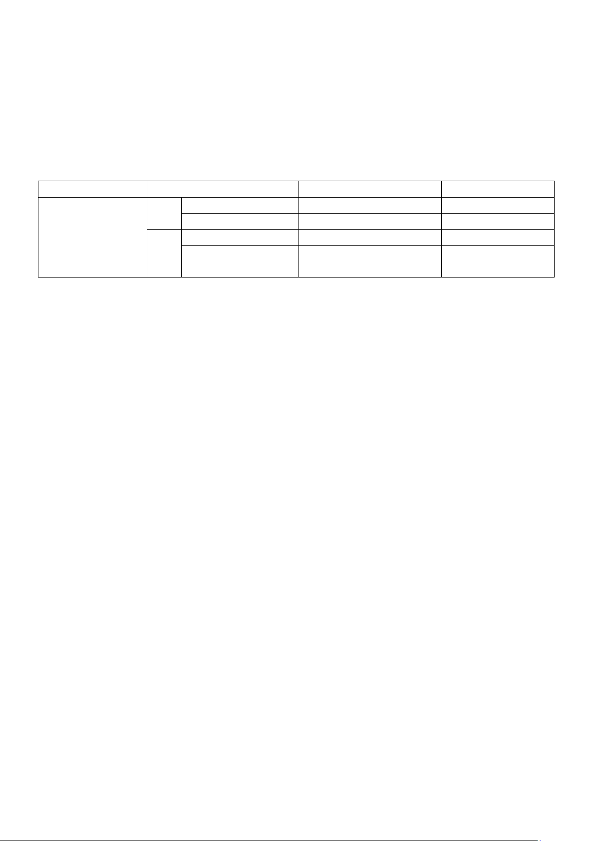
2.6 Conditions for ensuring long-time trouble-free working
Ambient temperature
Maximum Output Power
Suspend Time
Output Time Limit
t≤40℃
AC
>6mA
At least =the output time
Up to 1 minute
<4mA
No requirement
Can Continuous output
DC
>3mA
At least =the output time
Up to 1 minute
<2mA
At least=Charging Wait Time
(WAIT TIME)
Can Continuous output
Due to the dimension, weight, and actual use of the instrument, the voltage generation module of the
instrument has a small heat dissipation design. Therefore, the instrument is recommended for use in
the following ranges. If the fan has been in continuous operation for 30 minutes, the instrument must
be suspended; otherwise the amplifier output module may burn out due to overheating.
Prerequisites for withstanding voltage test
Note: Test time >= output time >= (voltage rise time + test time + voltage fall time)
2.7 Daily inspection
In order to avoid accidents, at least the following points must be guaranteed before using:
1. The input power of the instrument is in compliance with the specifications, and the power supply
of the instrument is configured correctly.
2. The instrument is reliably connected to the earth.
3. The test cable material is intact, no cracks, split and breakage.
4. The instrument is not connected to the test cable. The test is started under the default conditions
and the test can be completed successfully.
5. When connecting the test line to start the test, the low voltage terminal of the test line is in contact
with the high voltage terminal of the test line, and the instrument can generate a FAIL signal.
◇11
Page 12
Chapter 3 Panel Description
FUNCTION
ENTRY
PASS FAIL
JUDGEMENT
DANGER
START
STOP
POWER
F1
F2
F3
F4
F5
F6
PrtScn
FILE
TEST SETUP
OK
7
PQRS8TUV9WXYZ
4
GHI5JKL6MNO
1 2
ABC3DEF
0
+/-
ESC
BAS
2
1
3
4
5
6 7 8 9
10
13 12 111415
TH9010 PARALLEL MULTI-CHANNEL HIPOT TESTER
PAR1
PAR2
PAR3
PAR4
PAR5
PAR6
PAR7
PAR8
This chapter describes the basic operating characteristics of the TH9010 Series instruments. Before
using the TH9010 Series instruments, please read this chapter in detail so that you can quickly learn
the operation of the TH9010 Series.
3.1 Front Panel
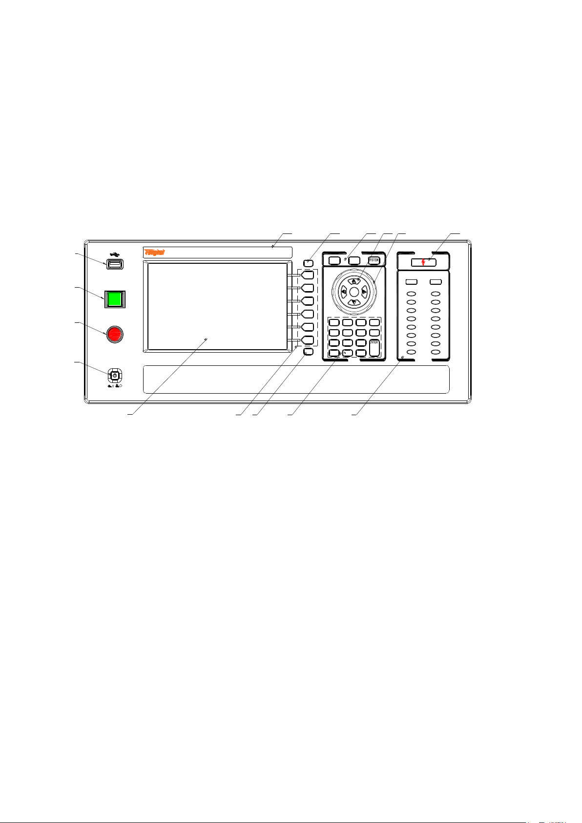
Figure 3-1 gives a brief description of the front panel.
Figure 3-1 Front panel description
3.1.1 USB Interface
It is used to connect an external USB memory.
3.1.2 Start Button
It is used to start the test and once the test starts, the DANGER indicator lights up.
3.1.3 Stop Button
The stop button is used to stop the test; it can also be used to cancel the PASS, FAIL and other
prompt states.
3.1.4 POWER
◇12
Power switch. Before the operator turns on the power for the first time, check the power supply
type of the instrument and the connection of the test lead.
3.1.5 LCD Display
800×600TFT dot matrix liquid crystal display, display setting interface, measurement interface, etc.
3.1.6 Shortcut Function Key
Functional operating area on the right side of the LCD, by default, it is F1-F6 from top to bottom,
Page 13

achieving quick operation.
3.1.7 File Function Key
It is used to save existing settings to the internal storage area of the instrument.
3.1.8 Numeric keypad
It is used to enter data for test parameters and modify the current set parameters.
3.1.9 Indicator Area
● FAIL
In the test, when a test data exceeds the setting, the instrument judges that the test failed, FAIL
indicator is on.
The upper indicator is the overall "FAIL" indicator and the lower indicators are for the test units.
When any test unit indicates "FAIL", the overall test result is "FAIL".
● PASS
After the test, no test data exceeding the initial setting was found, and the instrument judges that the
test passed, PASS indicator is on.
In the case of the test timing function is off (TIME OFF), the test can only end with ‘STOP’, no
PASS judgment.
The upper headlight is the overall "PASS" indicator and the lower indicators are for the test units.
When any test unit indicates "PASS", the overall test result is "PASS".
3.1.10 High voltage indication and Work instruction
This light is on when the instrument is ready for high voltage testing or when performing high
voltage testing.
Note: When the light is on, the operator should stay away from the high voltage tester, test
cable and the tested items to prevent electric shock.
3.1.11 Cursor control switch
The arrow keys are used to select the items to be modified, and the OK button is used to confirm
that the current project needs to be changed and the modification is completed.
3.1.12 Code switch and knob
Work together with cursor control switch to implement the parameters modification
3.1.13 Test function area (FUNCTION)
Select the working state of the instrument: including test status, test parameter setting status, and
system parameter setting status.
● TEST
Press this button to light and the instrument enters the ready test state; only in this state the
instrument is allowed to start the high voltage test.
● SETUP
Press the button to light and the instrument enters the parameter setting interface; only in this state
the instrument will modify the test parameters.
◇13
Page 14
● SYSTEM
RS-232C
USB
LAN
110V/220V~50/60Hz
GPIB
贴标签
HV
OUTPUT
!
RTN/LOW
MAX
5kV AC
6KV DC
HV
OUTPUT
!
RTN/LOW
MAX
5kV AC
6KV DC
HV
OUTPUT
!
RTN/LOW
MAX
5kV AC
6KV DC
HV
OUTPUT
!
RTN/LOW
MAX
5kV AC
6KV DC
HV
OUTPUT
!
RTN/LOW
MAX
5kV AC
6KV DC
HV
OUTPUT
!
RTN/LOW
MAX
5kV AC
6KV DC
HV
OUTPUT
!
RTN/LOW
MAX
5kV AC
6KV DC
HV
OUTPUT
!
RTN/LOW
MAX
5kV AC
6KV DC
1
2
3
4
56789
10
12
SIGNAL
HANDLER
11
PAR1PAR2PAR3PAR4PAR5PAR6PAR7PAR8
Press this button to light and display the system setting interface (SYSTEM); it is used to
configure parameters not related to test but related to the test system, such as display,
communication, etc.
3.1.14 Copy
COPY the picture of the current screen to the USB memory, which must be pre-plugged into the
front panel jack.
3.1.15 Instrument Model Label
TH9010/A Parallel Multi-Unit Hipot Tester
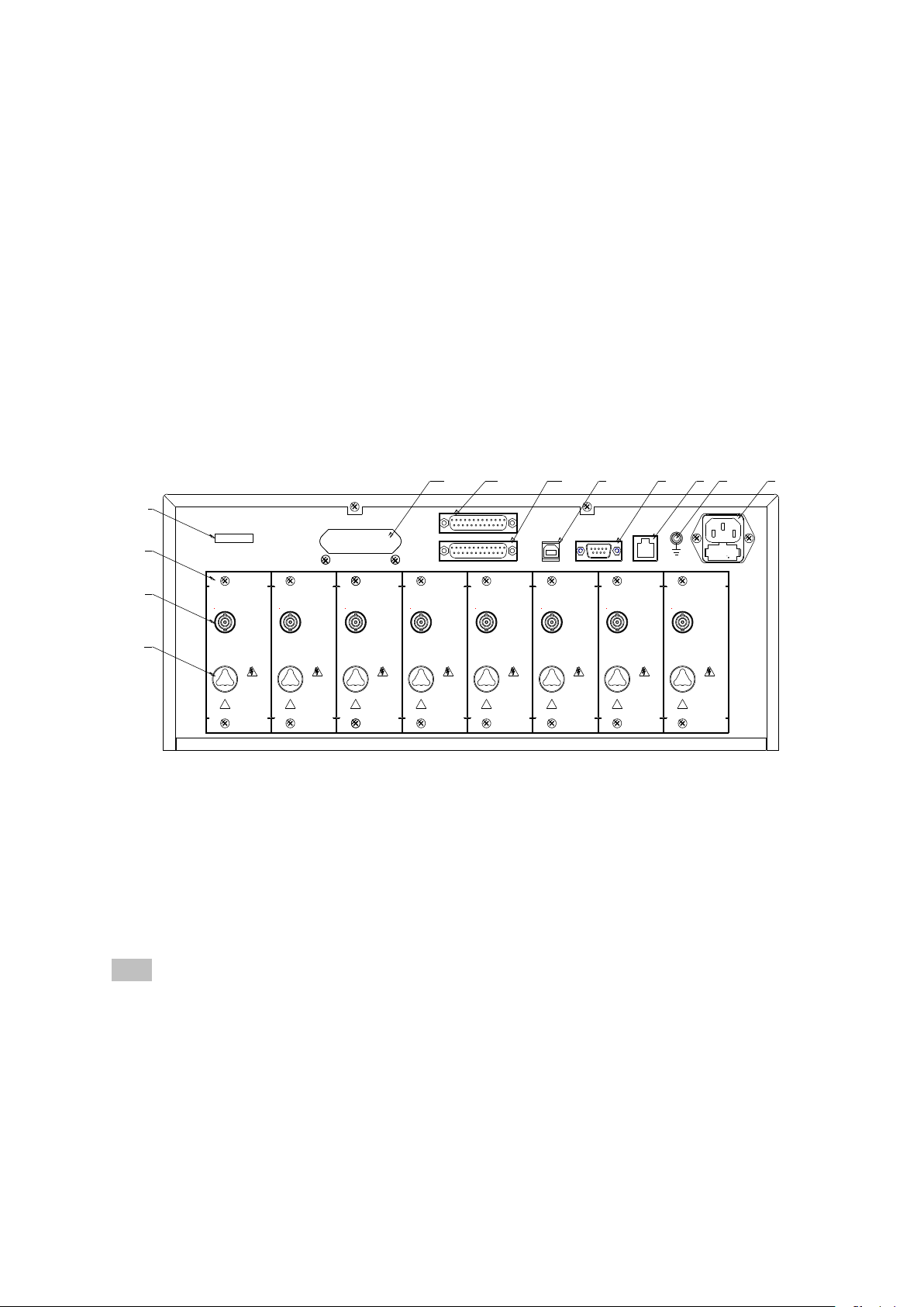
3.2 Rear Panel
Figure 3-2 gives a brief description of the rear panel.
Figure 3-2 Rear panel description
3.2.1 Product Name Plate
Information code for product model and date of manufacture
3.2.2 Test unit output module
Parallel high-voltage output control module, 8 for TH9010 and 4 for TH9010A. Each module is
independent of each other and can test a single DUT.
Note: Do not connect different test units to the same DUT, otherwise there will be unpredictable
risks.
3.2.3 Test low terminal, test current return terminal (one per test unit)
Test low terminal of parallel high voltage test interface; all test low terminals have loop ground,
please pay attention to distinguish when conducting parallel test wiring. Wrong connection will cause
wrong judgment of the instrument and unpredictable risk.
◇14
Page 15

3.2.4 High voltage output terminal (one per test unit)
High voltage output terminal of high voltage test interface.
3.2.5 Power socket: self-contained fuse box
For input AC power, please use the voltage within the specified input voltage range of the instrument.
Please use the power cord that comes with the instrument.
3.2.6 Protective ground terminal
The three-pin power socket that is plugged into the instrument power supply cannot guarantee reliable
connection to the earth, and then it must be connected to a reliable ground bar from here.
Note: Do not use the instrument without connecting to the ground. Otherwise, the instrument
chassis may be charged and there is a danger of electric shock.
3.2.7 LAN Interface
LAN communication interface to communicate with the computer.
3.2.8 RS232C serial interface
Serial communication interface to communicate with the computer. See Chapter 6 for the
communication command set.
3.2.9 USB serial communication interface
To communicate with the computer, the computer can control the instrument with the control
instruction set through this interface. See Chapter 6 for the communication command set.
3.2.10 HANDLER interface
Control and output interface for connecting the instrument to external control devices, there are
default mode and custom function mode, some pin functions can be customized.
3.2.11 SINGLE interface
Interface for outputting dedicated signals, currently used to connect multiple scan controllers
3.3 Multi-unit scanner description
Multi-channel scanners are equipped with multiple connection ports for each unit, used to connect
multi-port products, in order to implement product multi-parameter testing. TH90101 is compatible
with TH9010 and TH90101A with TH9010A.
Front panel picture:
◇15
Page 16
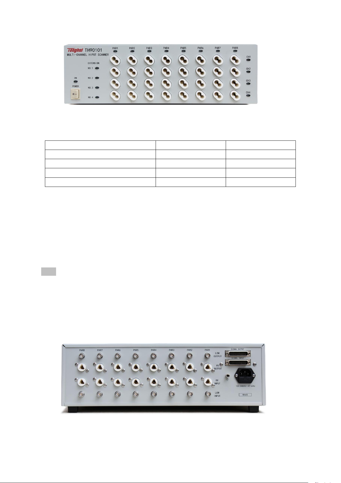
3.3.1 EXTENSION: serial number of the current controller
Host Scan Chanel
Controller Serial Number
1-4 Scan Chanel
#1 Controller
1-4 Scan Chanel
5-8 Scan Chanel
#2 Controller
1-4 Scan Chanel
9-12 Scan Chanel
#3 Controller
1-4 Scan Chanel
13-16 Scan Chanel
#4 Controller
1-4 Scan Chanel
Each host can expand 4 controllers, in the order of connection 1-4, the corresponding indicator will
light when the instrument sends data.
3.3.2 UNIT n: Unit n
Input unit indication, light on indicates that the current unit of the host is working. An erected row of
output ports is the scan terminal of the same port.
3.3.3 CH n: scan channel n
Scan channel connection indication, the red light indicates that this channel is connected to the high
voltage input of the unit input; the green light indicates this channel is connected to the current
feedback input of the unit input.
Note: One output of the controller is a double-wire output.
If you need to implement the CK (Contact Check) function, you need to connect the two ends to two
different contact points on the same pin of the DUT, or can be connected to different pins connected
via small impedance.
If you do not need to implement the CK (Contact Check) function, the withstanding voltage
between the two wires of the same channel does not exceed 100V, please do not apply a high
voltage signal here to avoid danger.
Rear panel picture:
◇16
Page 17
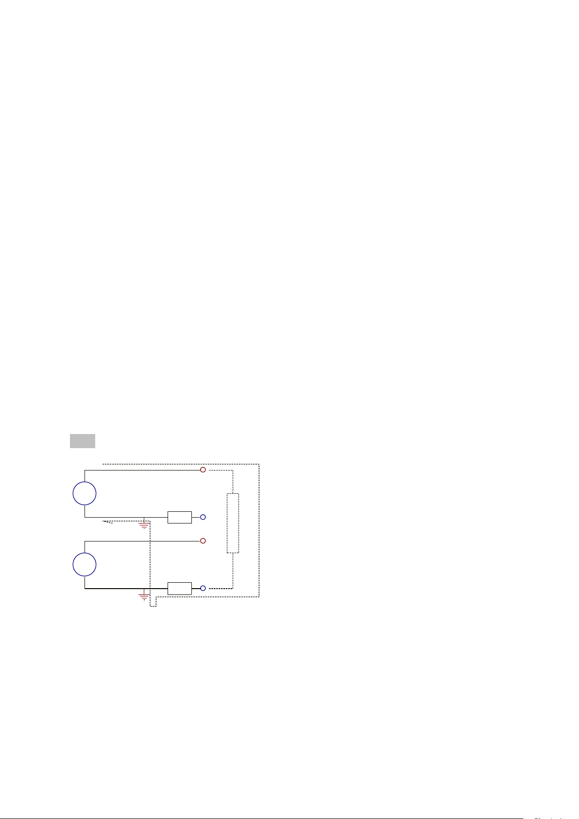
3.3.4 SIGNAL IN/OUT: Control signal input (female) / output (male)
GND
GND
HV1
HVn
Rx
HV1
RNT1
HVn
RNTn
A
A
I1-n
Control uses series control and the input terminal is connected to the host or the output signal that is
switched through the controller. The output terminal is used to connect to the signal input terminal of
the next controller, to achieve control signal switch.
3.3.5 UNIT n INPUT/OUTPUT: Unit n input / output
The input is connected to the output high voltage and current sampling of the corresponding unit of
the host. The output is used to connect the input high voltage and current sampling of the
corresponding unit of the next controller to realize the switching of the test voltage and current. The
input / output terminals of the test voltage are actually connected inside the instrument and can be
used interchangeably. The same is true for the current terminal.
3.3.6 Power Input
Connect the mains power supply to 100~240AC, 47-60Hz.
3.4 Instrument Performance Overview
The TH9010/A can provide 8/4 parallel test withstand voltage units, and the test units are independent
of each other. The 8/4 unit means 8/4 times the safety test speed.
TH90101/A scan controller can extend 4 scan channels per test unit, and the TH9010/A can control
up to 4 units. Used to connect test products with test endpoints no larger than 16. By connecting the
matching test fixtures, the multi-parameter test can be completed once the product is placed.
The output of each test unit is the same: 5kVAC/10mA withstand voltage, 6kVDC/5mA withstand
voltage, 1kVDC/5mA insulation resistance test.
Note: Each unit of test product must be strictly isolated. The reasons are as follows:
Because one point in the test low end of each unit structure is connected to the ground. Current is
collected between the low end of the test and ground. The current loop of the high voltage of
adjacent units can be achieved through the low end of the other units. The effect of this current on
the measurement is as follows:
1. This current flows through the current sample, the current sample value of this path is counted.
2. This current is the ground current, two loop ground current misjudgments occur when GFI is
turned on.
3. This current is too large to cause SHORT protection of the high voltage source and current
◇17
Page 18

sampling circuit HI FAIL
The following is a detailed description of the test unit parameters:
The principle structure of the test unit: The high voltage module is a DA reference, controllable
sine generator, PWM amplifier, 40 ~ 600Hz high voltage transformer boost, output voltage
closed-loop control loop.
1. DA reference: Ensure that the output voltage amplitude can be programmed.
2. Controllable sine generator: it can be set to work at 50 or 60Hz when AC output, no longer
limited by line voltage.
3. PWM power amplifier: high efficiency, good output performance and high sensitivity.
4. 40 ~ 600Hz high voltage transformer boost: for the power supply ripple problem of DC and
Insulation Resistance test, this instrument produces 600Hz AC power, after rectification, a DC
voltage is formed as a power source, to ensure that the DC power supply ripple is much smaller
than the previous regulator type old withstand voltage meter
5. Output voltage closed-loop control: The load regulation rate is small and the test data is
reliable.
Instrument software: multi-parameter continuous test, a variety of PC control functions.
TH9010 series are equipped with HANDLER, RS-232C, and USB, enabling the instrument to adapt
to a variety of automated test systems that require high safety and reliability.
Test unit features:
Four test functions—AC withstand voltage test, DC withstand voltage test, insulation
resistance test, open short detection When connected to the load, the instrument can
continuously perform multi-parameter testing by editing the test file.
Multi-unit scanning channel function (optional controller)
TH9010/A with multi-channel controller TH90101/A can realize 4, 8, 12, 16 programmable
scanning channels. Work with suitable test fixtures, programmable fast connection of
components can be realized, the test speed of multi-parameter measurements can be multiplied.
Node connection check CK: The scan channel of the scan controller is a two-wire parallel
structure, when the two-point connection is realized through the pin of the DUT, the
instrument performs the test of the connection reliability of the test node by performing the
continuity test.
Test power
Each high voltage module of the TH9010 series is a PWM power amplifier circuit and a 50VA
high voltage transformer, to achieve AC: 5kV/10mA, DC: 6kV/5mA output, the distortion of
the waveform is less than 3%. If the customer need to continuous current output, in order to
ensure the reliability of the instrument, maximum output time is 60 seconds when working
above 60% of rated output current. Within 60% to 40% of the rated output current, please pay
attention to the continuous working time. Continuous operation is guaranteed below 40% of
rated output current.
◇18
Page 19
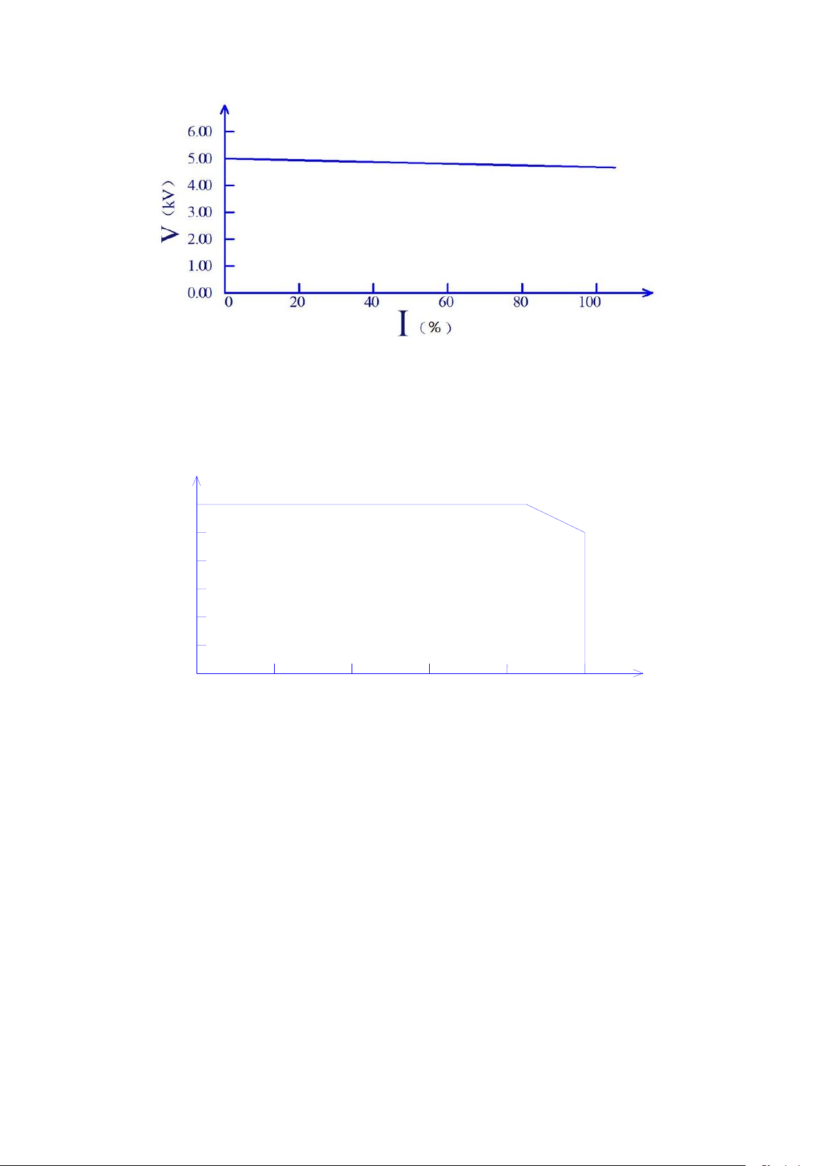
Figure 3-3 AC voltage load regulation
0.00
1.00
2.00
3.00
4.00
5.00
6.00
0 1 2 3 4
5
DC withstand voltage test 6kV/5mA
TH9010 Series provides DC withstand voltage test over a wide voltage range (maximum
output DC 6kV). Automatic voltage adjustment of 600Hz frequency hardware, voltage load
regulation rate ≤1%+10V.
Figure 3-4 TH9010/A DC Voltage Output Range
Insulation resistance test 0.050kV to 1.000kV (1V resolution) / 0.1MΩ to 10.0GΩ, the
maximum rated current is 5mA
Insulation resistance test range:
When the voltage is less than 500V: 0.1MΩ ~ 100MΩ Accuracy is ± [10% reading + 5 digits]
When the voltage is greater than 500V: 1MΩ ~ 100MΩ range accuracy is ± (5% reading + 5
digits), 100MΩ ~ 1GΩ range accuracy is ± (10% reading + 5 digits).
Open short circuit detection: Before starting high voltage, please determine whether or
the DUT is reliable connected, to ensure that the high voltage test is accurate and safe.
Open short circuit detection can determine the distributed impedance current above 100PF, less
than this value; the resolution of the current acquisition circuit of the instrument cannot
accurately distinguish the open circuit and the test component connection.
RS-232C interface as standard
Except power conversion, key lock, other functions can be remotely controlled. Test
conditions such as test voltage, judgment function, and test time in DC withstand voltage test,
◇19
Page 20

AC withstand voltage test, and insulation resistance test can be remotely controlled. Test
results can also be read from behind through remote control. The USB and RS-232C
interfaces provide a stable and standardized standard test interface with PCs or other devices.
HANDLER interface for easy connection control
HANDLER interface: You can input START, STOP signal, and output TEST, PASS, FAIL
signals. Can be connected to the foot switch easily, connect with simple test fixtures for safety
interlocks, pneumatic controls, test indications, and more. Internal or external 24V power
supply can be used as the output interface power supply for easy control and connection.
USB interface for backup
The instrument is equipped with a USB interface, which can save the test files written by the
instrument and customer measurement files to an external USB flash drive, or load the files
from a USB to the instrument to conveniently set the usage parameters and archiving scheme
of the instrument in batches.
Test waiting time setting
The test waiting time can be set from 0.1s to 999.9s with a resolution of 0.1s. During this time,
the instrument will output a test control signal to control the external device to ensure reliable
test connection, and then start the high voltage test process.
Rise time control function
In AC withstand voltage test, DC withstand voltage test and insulation resistance test, the test
voltage can slowly rise to the set value instead of providing the set voltage to the DUT
immediately after starting the test. The voltage rise timecan be set from 0.1s to 999.9s with a
resolution of 0.1s. TH9010 series meets various UL test standards and IEC withstand voltage
test standards. (Rise time can be specified when the initial voltage is less than half of the test
voltage and when the set test voltage is reached).
Drop time control function
In the qualification judgment of the AC withstand voltage test, the test voltage can be
gradually reduced. The voltage drop time can be set between 0.1s and 999.9s with a resolution
of 0.1s.
Discharge function
Usually the tested part is capacitive. At the moment when the DC withstand voltage test and
the insulation resistance test are cut off, the DUT remains fully charged, therefore there is a
danger of electric shock. The TH9010 series has a forced fast discharge function on the DUT
after the DC withstand voltage test and insulation resistance test are completed.
Enhanced security
For improving safety, the TH9010 Series is equipped with many facilities and safety features,
include safety outputs, discharge function and ground current detection. The so-called ground
current detection is that when the return current of the ground high voltage test circuit is
greater than 0.5mA through the chassis, high voltage output is cut off.
Higher test accuracy
TH9010 series voltage digital display, voltage test accuracy is ± (1% reading + 5V) during
withstand voltage test, voltage accuracy is ± (2% reading + 5V) during insulation resistance
test. The accuracy in the withstand voltage and current test is ± (2% reading + 5 digits).
Current clear function
AC and DC withstand voltage test requires high voltage and high current sensitivity,the
◇20
Page 21
current flowing through the stray capacitance of the test leads and fixtures will make the test
!
inaccurate. The TH9010 series has a current clear function to offset the current fluctuation.
Easy operability
TH9010 series is easy to operate, ensuring that users do not have difficulty to use. The
instrument lists all test parameters in the setting interface. Use the arrow keys to select a
parameter from the LCD display interface, then use the function button to modify the
parameters, customers can start to test after setting the data.
Files can be saved inside the instrument: 20 files can be saved, and each file can have 20
test steps
It can edit 20 test files, corresponding to the various test project combinations required by
customers, each file can have up to 20 test steps, the test procedure is any one of the AC
withstand voltage test, the DC withstand voltage test, the insulation resistance test, and the
open circuit short circuit determination, test conditions for each step are not related to each
other; The stored file can be transferred to a computer or another similar instrument through an
external USB in the file operation interface.
Multi-unit scan controller function description: (optional)
After the instrument is connected to the multi-unit scan controller, the instrument will have a
corresponding scan channel value that can be set, the customer can set to connect the scan
controller port with high voltage or current return terminal of the test unit as needed.
Contact inspection can be achieved:
Single-ended inspection: When connecting the test end of the instrument, connect the two
test leads of the same port to two different positions on one of the pins of the DUT. The
withstand voltage between the two contact points does not exceed 100V.
Double-ended inspection: When connecting the test end of the instrument, connect the
two test leads of the two ports to two different positions of a pin of the DUT, or connect
two pins with low impedance (several ohms to tens of ohms).
Warning:
The instrument uses a high voltage of 5kV AC / 6kV DC, do not touch the DUT and the test leads,
there is a danger of electric shock.
Around the DUT, security measures such as fences should be provided.
When the safety measures such as the fence are not in a safe state, please disconnect the INT LOCK
signal jumper to ensure the safety of the user.
To ensure safety, it is recommended to disconnect the INT LOCK signal jumper when high voltage
is not required. When it is necessary to start the high voltage, be sure to carefully check the high
voltage test cable and there is no sundry near the DUT which may affect safety.
◇21
Page 22
Chapter 4 Basic operation
SETUP
Ext.File
SYSTEM
Int.File
OS
STEP:01/01
FILE
AC parameters
File modification
and inspection
AC
Test
IR
DC
TEST
Start Test
CK (channel
control)
Envi
I/O
LOAD
SAVE
4.1 Interface structure overview
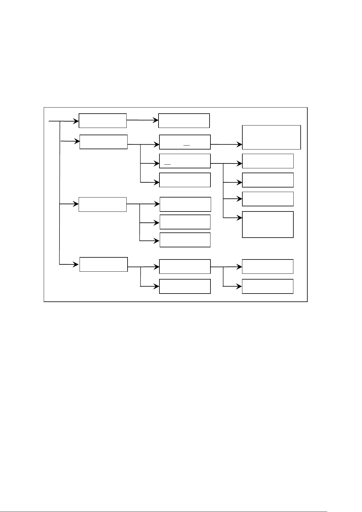
The following figure is the interface structure:
Figure 4-1 Operation Steps
Interface Instructions:
The first column of the interface structure is called according to the panel function button.
TEST interface cannot modify parameters.
The second column of the interface structure is the parameter structure of the initial interface.
For example, the SETUP interface defaults STEP 01/01: scenario step 1, total steps 1,AC: AC
withstand voltage test interface, AC parameters: Other parameters are test parameters of AC
withstand voltage.
The third column of the interface structure is the function switching interface. These features
can be changed when some feature identifiers are selected in the second interface, the relevant
parameters of this interface will change. For example if the AC is changed to DC, the
instrument will change the AC withstand voltage test mode to the DC withstand voltage test
mode, the 'AC parameter' of the current interface will change to the 'DC parameter' that the DC
withstand voltage needs to be set.
Note: The instrument only saves data changes when switching interfaces. After modifying
the data in the SETUP interface and SYSTEM interface, please switch the interface to
◇22
Page 23

the "TEST" interface.
TEST (test key):
Let the instrument enter the test wait state, ready to start
the high voltage test. (Power on defaults to this interface)
SETUP(setup key):
This is the interface used to modify the current test file,
test project, test parameters. The modification of the test
file is completed in this interface.
SYSTEM(system key):
Test safety and instrument operating mode related settings,
it has little to do with test files. Press multiple times to
switch the sub-interface.
FILE(file key):
Test file save and call interface, it is related to data storage.
Press multiple times to switch the sub-interface. Note:
Call may have a version mismatch problem.
(direction key):
In this interface, press the cursor up, down, left, and right.
Knob:
In this interface, move the cursor quickly in order.
F1~F6(soft key):
Work with the right area contents of the soft key function
displayed to achieve quick modification.
0~9(numeric keypad):
Modify the data at the cursor position, please refer to the
information prompt area at the bottom of the screen to
determine the data input range.
4.2 Panel function interface and parameter description
This section introduces the functional interface and related parameters of the instrument based on the
software flow and interface correlation, to guide users to understand the function and use of the
instrument.
Instrument initial status description
1. Turn on the instrument, it will self-test, query the existing unit and scan controller
2. After booting, the system enters by default: TEST interface
3. The default data is the test data when the last interface was switched before the last
shutdown.
4. The factory default setting of the instrument is single step, AC withstand voltage, default
parameter status.
The interface switching of the instrument can be directly switched by using four function keys, they
are:
Measurement display (TEST): Start the high voltage test process.
Measurement setup (SETUP): Modify the high voltage test procedure
System interface (SYSTEM): Modify the conditions related to the instrument system
File processing (FILE): Save and recall the set test file from the instrument storage area or USB
The basic function description of the button:
Note: The instrument will save the data modification only when the interface is switched.
After modifying the data in the setup interface and system interface, you must switch the interface.
Please be careful not to shut down directly after modifying the data to avoid data loss.
◇23
Page 24
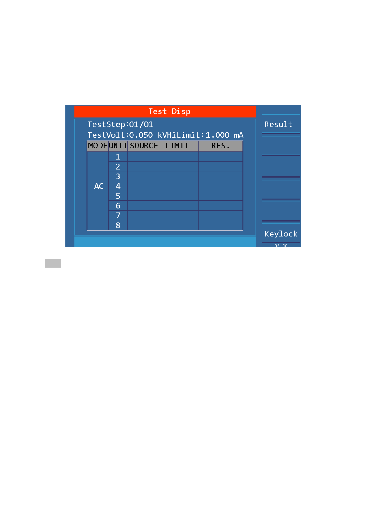
4.2.1 Test Interface
The test interface is used to start the test process to test the DUT according to the existing
requirements.
Use the "TEST" button to enter
The interface is as follows: (taking AC as an example)
Figure 4.2.1 AC Test Interface
Note:
1. High-voltage measurement of the DUT can be started in the TEST interface. Parameters
modification can not be done in this interface.
2. the instrument high voltage start must meet:The "INT LOCK" instrument online lock signal of
the HANDLER interface is closed.(TH9010-IL plugged into the HANDLER interface)、the
"STOP" button is not pressed , any "START" button is pressed.
3. Press (direction key) on this interface can quickly switch to the (SETUP) interface.
4. F6 function key can lock the key board, the instrument responds only to the INT LOCK, START,
STOP, and F6 (unlock) keys after the keyboard is locked, note that the unlock operation is
controlled by the password setting of the system environment interface.
After the measurement is started, the instrument displays the real-time test data displayed in the test.
At FAIL, the instrument determines the working method according to the failure mode function. See
the interface parameter description for details.
When all test steps are completed, PASS, the instrument will display the total PASS test result, after
waiting for a certain period of time, it will automatically return to the test waiting state.
When all test steps are completed with FAIL, the instrument will display the FAIL test results.
Press the STOP button to return to the test wait state.
4.2.2 Setup Interface
The SETUP interface is used to set test items according to the safety requirements of the product, and
arrange the test sequence. Press the "SETUP" button to enter
◇24
Page 25
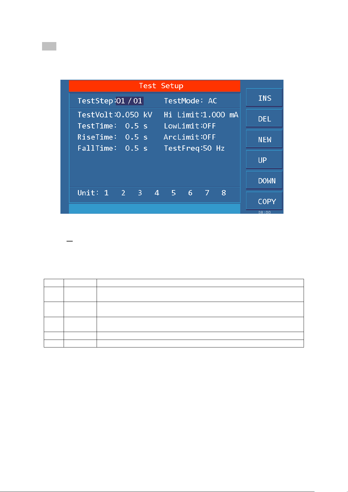
Note: After modifying the data in the SETUP interface, switch the interface to TEST and the
Key
Fun.
Description
F1
INS
Add a new test step after the project, the test item for this step is the default.
The current project and the following projects will be moved one bit later.
F2
DEL
Delete current test step and test item. the next step project will move forward
one bit
F3
NEW
Create a new empty test file (STEP), the system will automatically create a
new default step and test project.
F4
+
Access the parameters of the previous step of the current display step
F5
-
Access the parameters of the step after the current display step
instrument will save all data modifications. Please be careful not to shut down directly after
modifying the data to avoid data loss.
The interface is as follows:
Figure 4.2.2 AC SETUP Interface
Test file modification instructions
STEP: 01/01 Step number of the current project/Total number of steps
The test step value is the serial number of the current test item in the test file, that is, the order in
which the test files are tested.
Project ID of the test file, the current parameter is nth step of the test file / total steps
Test items: AC withstand voltage (AC) The test item of the current test procedure is AC
withstand voltage.
The test item of the current test procedure is AC withstand voltage, when the cursor is in this
position, you can switch to DC, IR, OS items via F1~F4.
For the parameter modification of the test project, see "4.3 Test Project Interface and
Parameter Description"
4.2.3 System Interface
The interface is as follows:
The system interface is to set some settings that are not related to the test project, but related to test
◇25
Page 26
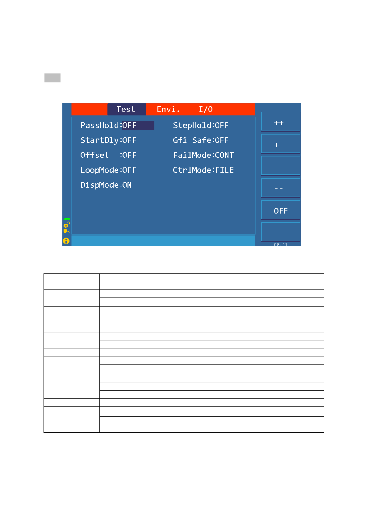
result processing, test process control, and instrument communication scheme.
Setting Mark
Parameter
value
Description
PASS HOLD
OFF
OFF, PASS signal output time
0.2~99.9S
When the test is passed, the hold time of the pass judgment.
STEP HOLD
OFF
OFF, waiting time between steps
KEY
Pause, press ‘START’ key to start the next step
0.1S~99.9S
Time to wait between steps during multi-step testing
STRT DLY
OFF
OFF, test wait time
0.1~99.9S
Start and test the waiting time between the first item
GFI
ON, OFF
Ground current detection, enabled.
OFFSET
ON, OFF
Test data clear is enabled.
GET
Get the existing status data as zero data.
FAIL MODE
STOP
If it fails, exit the test state directly.
CONT
If it fails, continue the test and the results can be queried.
PAUS
When the unit fails, the current unit test is suspended
LOOP MODE
ON, OFF
Perform an uninterrupted loop test on existing files.
CTRL MODE
FILE
The file ends and the interface output the test results.
STEP
At the end of each step, the interface outputs a single step
result.
Press the “SYSTEM” button to enter, press the “SYSTEM” button again to switch to the
sub-interface.
Note: After modifying the data in the SETUP interface and SYSTEM interface, you must switch
the interface to save all data modifications.
1. SYSTEM related sub-interface
Figure 4.2.3.1 Test SYSTEM related interface
Interface parameter description:
◇26
Page 27
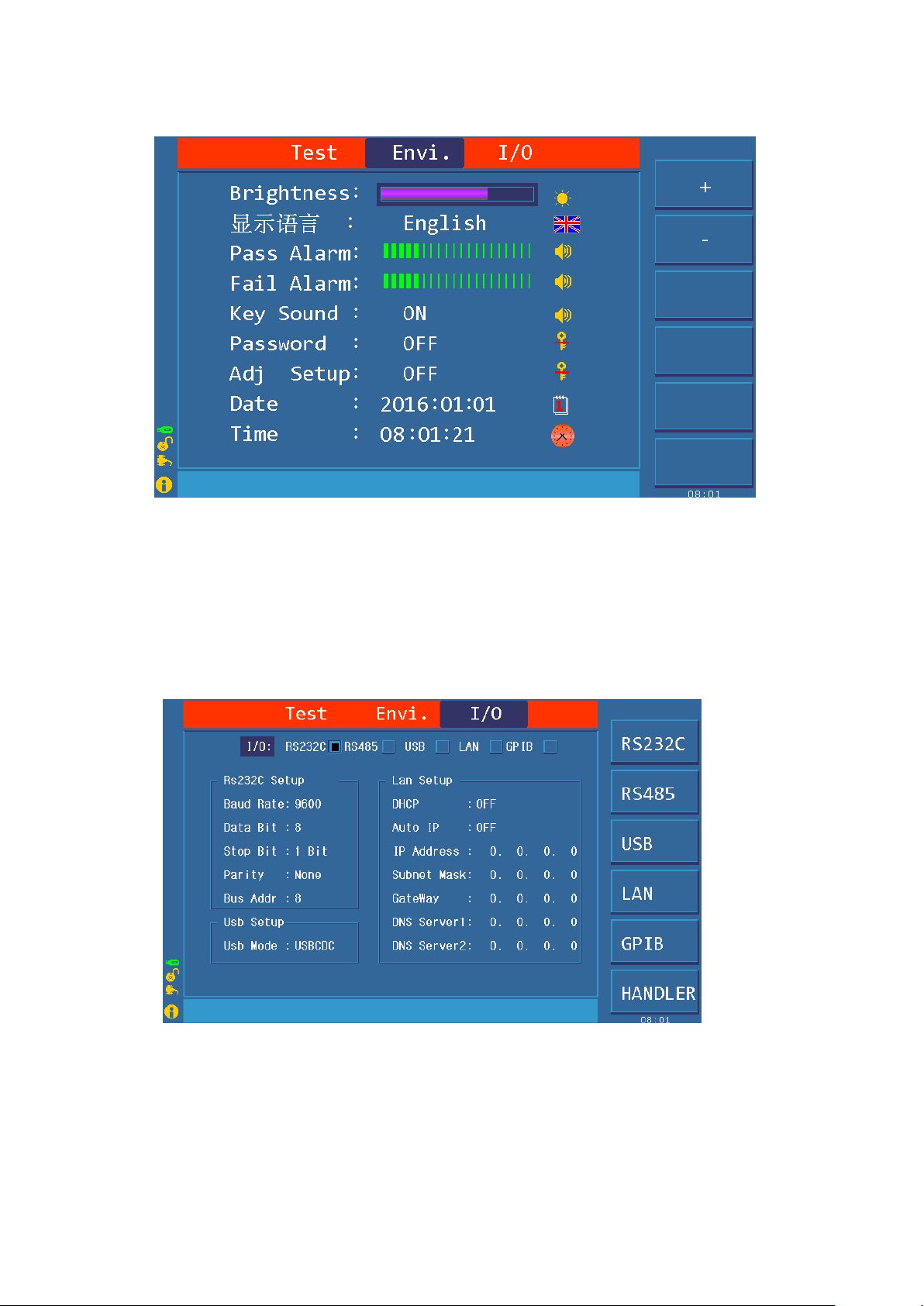
2. Test environment related sub-interface
Figure 4.2.3.2 Test environment related interface
Interface parameter notes:
Password setting (PASS WORD): Set the key lock password, the instrument default password:
666666.
The F4 function key of the password setting state is the system firmware upgrade button, the
firmware program must be inserted into the U disk of the instrument.
The F2 function key of the metering setting state is to restore to the factory default state.
3. Communication interface related sub-interface
Figure 4.2.3.3 Communication Interface Related Interface
Interface parameter notes:
1. RS485 uses RS232 interface, users need to use RS232-RS485 converter separately. The bus
address is invalid in RS232 mode.
2. GPIB is an option, please confirm when purchasing the instrument.
◇27
Page 28
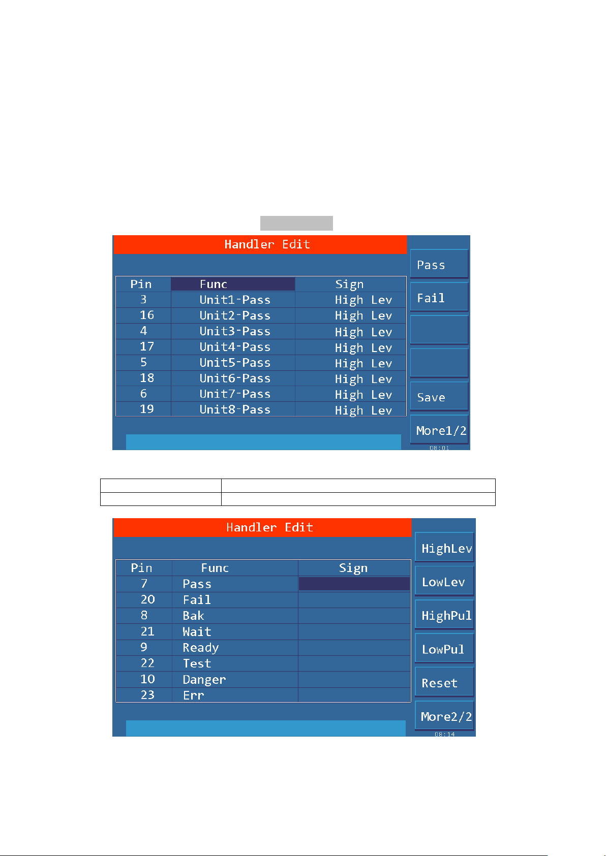
4. HANDLER communication interface setting
Setting Mark
Description:
UNIT <n>-PASS:
When the unit test passes, the signal is valid.
Level type description:
1. High Level: Active high at output and the output interface optocoupler is open. (Test board
indicator is off)
2. Low Level: Active low at output, output interface optocoupler is turned on. (Test board indicator
is on)
3. High pulse: hold time of output is about 250mS for high level
4. Low pulse: hold time of output is about 250mS for low level
For detailed description of the signal, see 4.6 HANDLER Interface Circuit Structure and Use
Figure 4.2.3.4 HANDLER Communication interface setting 1 related interface
Figure 4.2.3.5 HANDLER Communication interface setting 2 related interface
◇28
Page 29
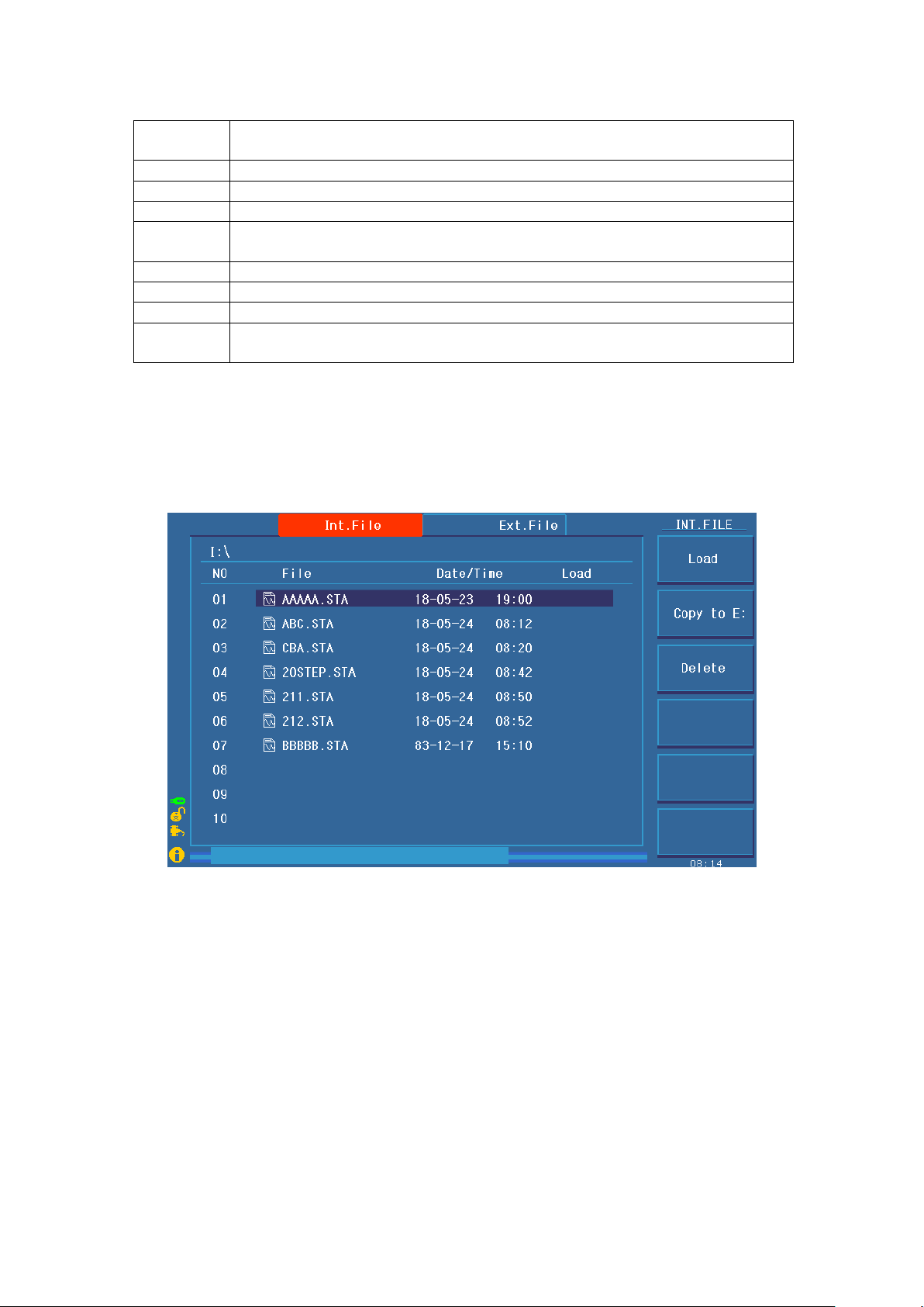
Setting
Mark
Description
PASS
At the end of the test, the signal is valid when all unit tests pass.
FAIL
At the end of the test, the signal is valid when all unit tests fail.
BAK
Undefined(Backup)
WAIT
When the test is started, when there is no output at high voltage, the signal is
valid.
READY
Non-test status of system idle, the signal is valid.
TEST
From pressing START to the end of the entire file test, the signal is valid.
DANGER
When there is high voltage output, the signal is valid.
PROG
ERR
System malfunction, the signal is valid.
4.2.4 FILE storage interface
The file interface is used to save the edited test file, or call a previously edited test file.
Press the “FILE” button to enter, press the “FILE” button again to switch the sub-interface.
The internal file operation interface is indicated:
Figure 4.2.4.1 internal file operation interface
◇29
Page 30
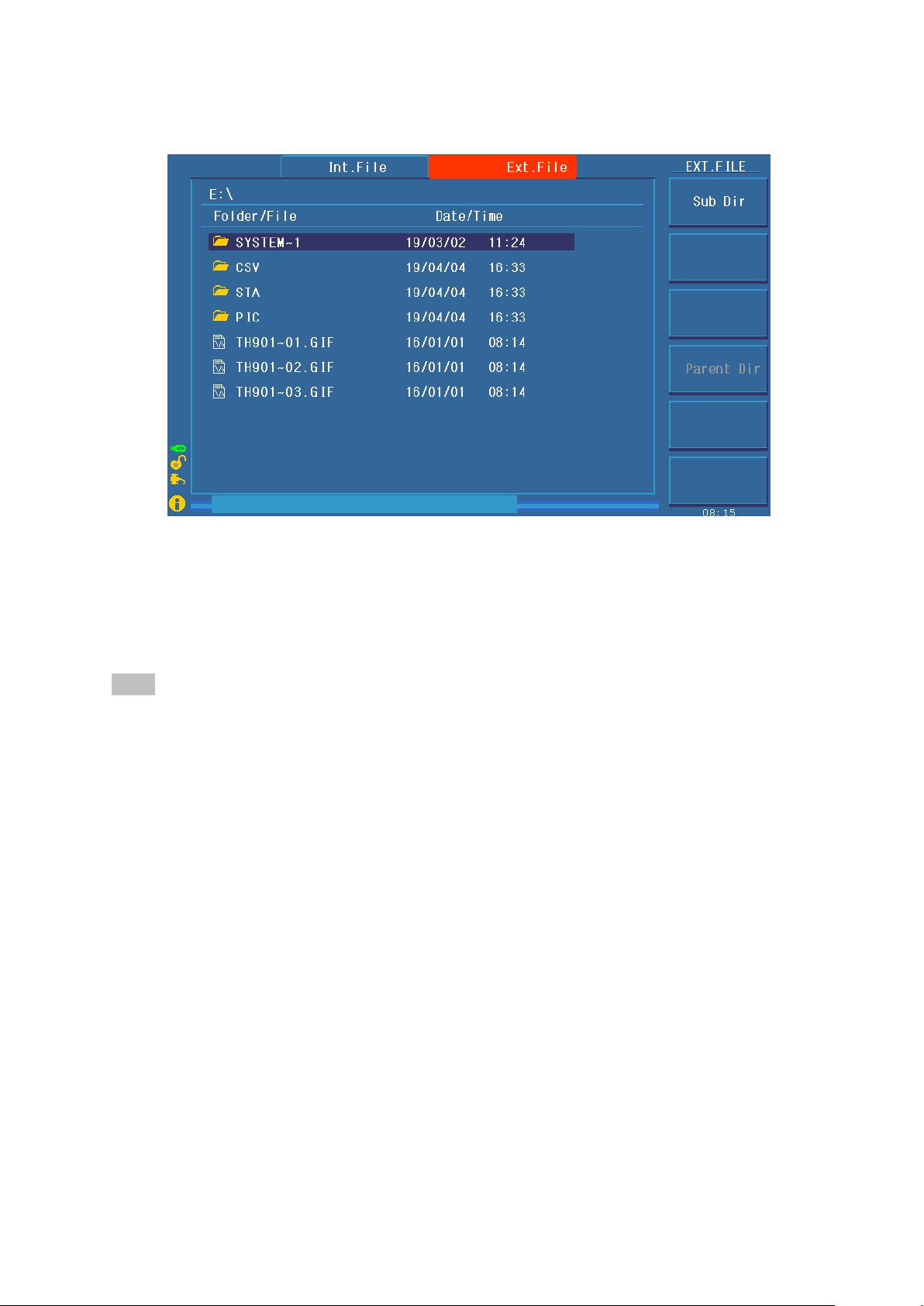
The external file operation interface is indicated:
Figure 4.2.4.2 External file operation interface
Interface Description:
1 I: internal file. Storage area divided inside the instrument, save or call the test file
2 E: External U disk storage file. U disk to store, save or call test files, enable to use the current
settings file on other instruments conveniently.
3 Internal copy to E:, The U disk is saved to the currently opened U disk directory by default, The
default state is the root directory.
Note:
1. Because the instrument system is simple, USB flash drive capacity should not exceed
8G; Store as few files or directories as possible, to avoid instrument reading failure.
2. Files of different program versions may not be compatible, if the test conditions of the
called file incomplete display, please restore the factory settings of the instrument,
re-edit the new test file.
4.3 Test project interface and parameter description
This section describes the test function parameters of the setting interface and their meanings, to guide
customers in setting relevant parameters.
Move the cursor to the test step, press "F1~F6" to modify the test file.
4.3.1 AC withstanding voltage test parameter setting
The setting interface is as follows:
◇30
Page 31
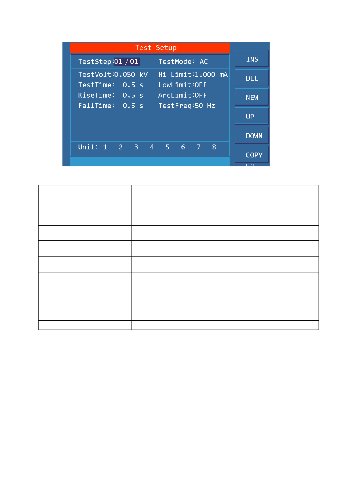
Figure 4.3.1 AC setting interface
VOLT:
0.050~5.000kV
AC high voltage test voltage value
UPPER:
0.001~20.00mA
TH9320 series AC withstand voltage current upper limit
0.001~10.00mA
TH9010 series AC withstand voltage current upper limit
LOWR:
0.001~20.00mA
TH9320 series AC lower limit current value, must be less than the
UPPER value
0.001~10.00mA
TH9010 series AC lower limit current value, must be less than the
UPPER value
OFF
Lower limit is not required
ARC:
0.1~20.0 mA
AC arc current maximum allowable
OFF
No arc is not required
TIME:
0.2~999.9S
AC withstand voltage test time, the test is end when the time is up
OFF
Test time is not required
RISE:
0.1~999.9S
AC high voltage test voltage rise time
OFF
Default=0.1S,Integration with test time
FALL:
0.1~999.9S
AC high voltage test voltage fall time
OFF
Directly cut off voltage output at the end of the test. (The DUT may
be charged)
FREQ:
50/60
AC working frequency
AC withstanding voltage (AC) test parameter description:
4.3.2 DC withstanding voltage test parameter setting
Move the cursor to the test mode, press "F1~F6" to modify the test mode of the current step.
The setting interface is as follows:
◇31
Page 32
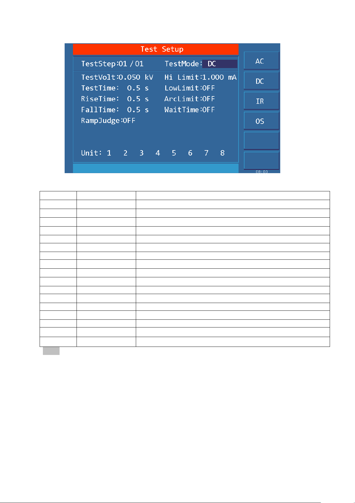
Figure 4.3.2 DC setting interface
VOLT:
0.050~6.000kV
High voltage test voltage value
UPPER:
0.1uA~10.00mA
Current upper limit
0.1uA~5.00mA
Current upper limit
LOWR:
0. 1uA~10.00mA
Current lower limit, should be less than the UPPER limit
0. 1uA~5.00mA
Current lower limit, should be less than the UPPER limit
OFF
LOWR is not required
TIME:
0.1~999.9S
test time, the test is end when the time is up
OFF
Unlimited test time
RISE:
0.1~999.9S
Test voltage rise time
OFF
Default=0.1S,Integration with test time
FALL:
0.1~999.9S
Test voltage fall time
OFF
End of test stop voltage output
WAIT:
0.1~999.9S
DC charging wait time
OFF
Components do not need to be charged
ARC:
0.1~20.0 mA
maximum DC arc current
OFF
ARC is not required
RAMP:
ON
When the voltage rises, to judge the current upper limit allowed
OFF
Do not judge current upper limit
DC withstand voltage (DC) test parameters are described below
Note:
1. After the DC test is over, the instrument will automatically perform a 0.2 second
rapid discharge.
2. During the waiting time, the instrument does not judge the current upper limit, but
the short circuit detection circuit is still working.
4.3.3 IR Insulation resistance test parameter setting
Move the cursor to a test condition, press "F1~F6" to modify the current test condition or
data.
The setting interface is as follows: (Figure 4.3.3)
◇32
Page 33
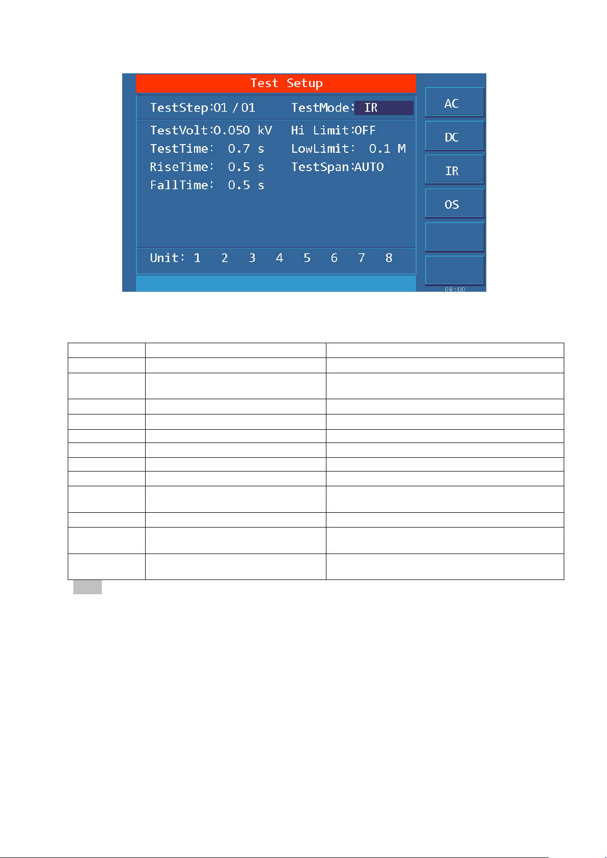
Figure 4.3.3 IR setting interface
VOLT:
0.050~1.000kV
Insulation test voltage value
UPPER:
0.1M~10.00G
Upper limit of IR
OFF
Do not judge the UPPER limit of the insulation
resistance
LOWR:
0.01M~10.0G
Lower limit of IR, should be less than Upper limit
TIME:
0.1~999.9S
IR test time
OFF
Unlimited test time
RISE:
0.1~999.9S
Insulation voltage rise time
OFF
Default=0.1S, Integration with test time
FALL:
0.1~999.9S
Insulation voltage fall time
OFF
Directly cut off voltage output at the end of the
test(The DUT may be charged)
RANG:
AUTO
Automatic range mode; Improve test accuracy
TH9320 series
2uA, 20uA, 200uA, 2mA, 10mA
Fixed range mode: can use I=U/R to estimate the
range to speed up testing
TH9010 series
1uA, 10uA, 100uA, 1mA, 5mA
Fixed range mode: can use I=U/R to estimate the
range to speed up testing
IR test parameters are as follows:
Note:
1. The instrument judges the upper and lower limits at the end of the test. The current short
limit is keeping working!
2. When in auto range, due to range switching, the minimum test time is 0.6S.
3. Due to current and voltage acquisition timing effects, voltage rise time and voltage fall time
show significant deviations in resistance values, hereby explain for your reference.
4.3.4 OS circuit test parameter setting
The setting interface is as follows:
◇33
Page 34
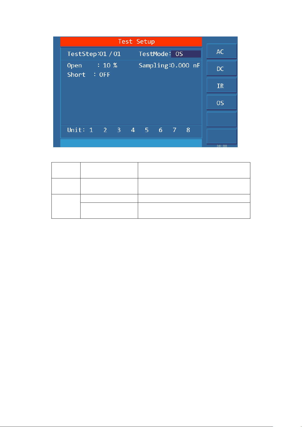
OPEN:
10%~100%, 1%
Open circuit determination threshold lower
limit
SHRT:
OFF~100%~500%
STEP: 10%
Short circuit determination threshold upper
limit
STAN:
Previous Standard
Standard Value (check remark)
GET
Get the current distribution parameter as the
standard value
Figure 4.3.4 OS setting interface
Open short circuit detection (OS) test parameters are as follows
Remarks:
1. When the cursor is at the standard value (above figure) position, (F5) Function key position
display (GET).
2. Press the (F5) function key at this time, the instrument enters the standard value sampling
state. When sampling, the instrument will output a voltage of 100V to automatically obtain
the current flowing through the DUT within 100 milliseconds. (There is voltage output when
GET, be careful)
3. The capacitance value displayed by the instrument here is not the actual capacitance value,
but the value of the sampled current after impedance conversion, which should be similar to
the actual installed capacitance between the test terminals. (The sampled current is not just
generated by the capacitor)
OPEN SHORT value setting: When the fixture's open circuit capacitance value >> component’s
open circuit capacitance value
Open value: greater than the value of the instrument not connected to the DUT, less than the
minimum value of the connected DUT
Short value: Greater than the maximum value of the connected DUT, less than a larger value that
may be caused by other defects.
Taking a coil as an example: Capacitance between coils is about 50P
1. Do not connect the DUT, "GET" test fixture open value :STAN=10-20P,
Confirm open circuit value 20P.
2. Connect multiple DUTs to record GET data range: STAN=50-70P to confirm
◇34
Page 35
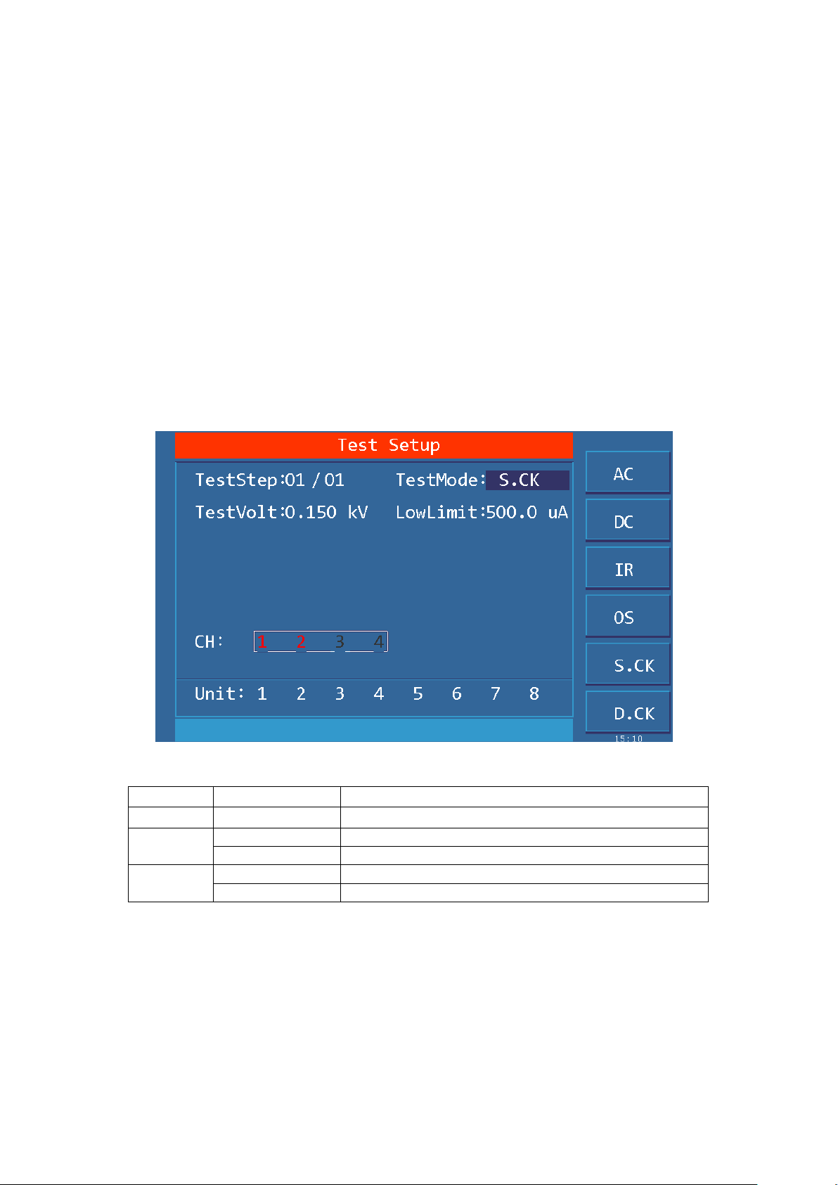
standard value 60P.
VOLT:
0.50~0.500kV
High voltage test voltage value
UPPER:
0.1uA~5.00mA
Current upper limit
SCAN:
Red
This port performs contact check
Gray
This port ignores contact check
UNIT:
White
This unit participates in the test
Gray
This unit does not participates in the test
3. Connect multiple damaged DUTs to record GET data range: STAN >100P to
confirm short value
Parameter setting calculation:
Assume that STAN is set to 60P.
Open value: Lower Limit=20P/60P=33%, OPEN Upper Limit=50P/60P=83%. Recommended to
take 60%
Short value: Lower Limit=70P/60P=117%, Upper Limit=100P/60P=160%. Recommended to
take 140%
4.3.5 S.CK Single-ended contact check parameter setting
It is valid to connect multi-channel scan box.
S.CK Function: to check if two test leads of a scan port are connected reliably. Generally, it is
connected to the same pin of the DUT, if connected to the connected pins, not greater than 100V.
The setting interface is as follows:
Figure 4.3.5 S.CK setting interface
Contact Check (S.CK) The test parameters are as follows:
Description:
1. The actual current is related to the internal resistance of the test loop. The default is the preferred
configuration
2. The test status is DC power open loop mode, setting parameters and test values are for reference
only
3. All test points are checked in one test process, test time is configured by test points, after the test is
over, the instrument will automatically perform a 0.2 second rapid discharge.
4. Total test time = 0.5S + 0.3S * N.
◇35
Page 36
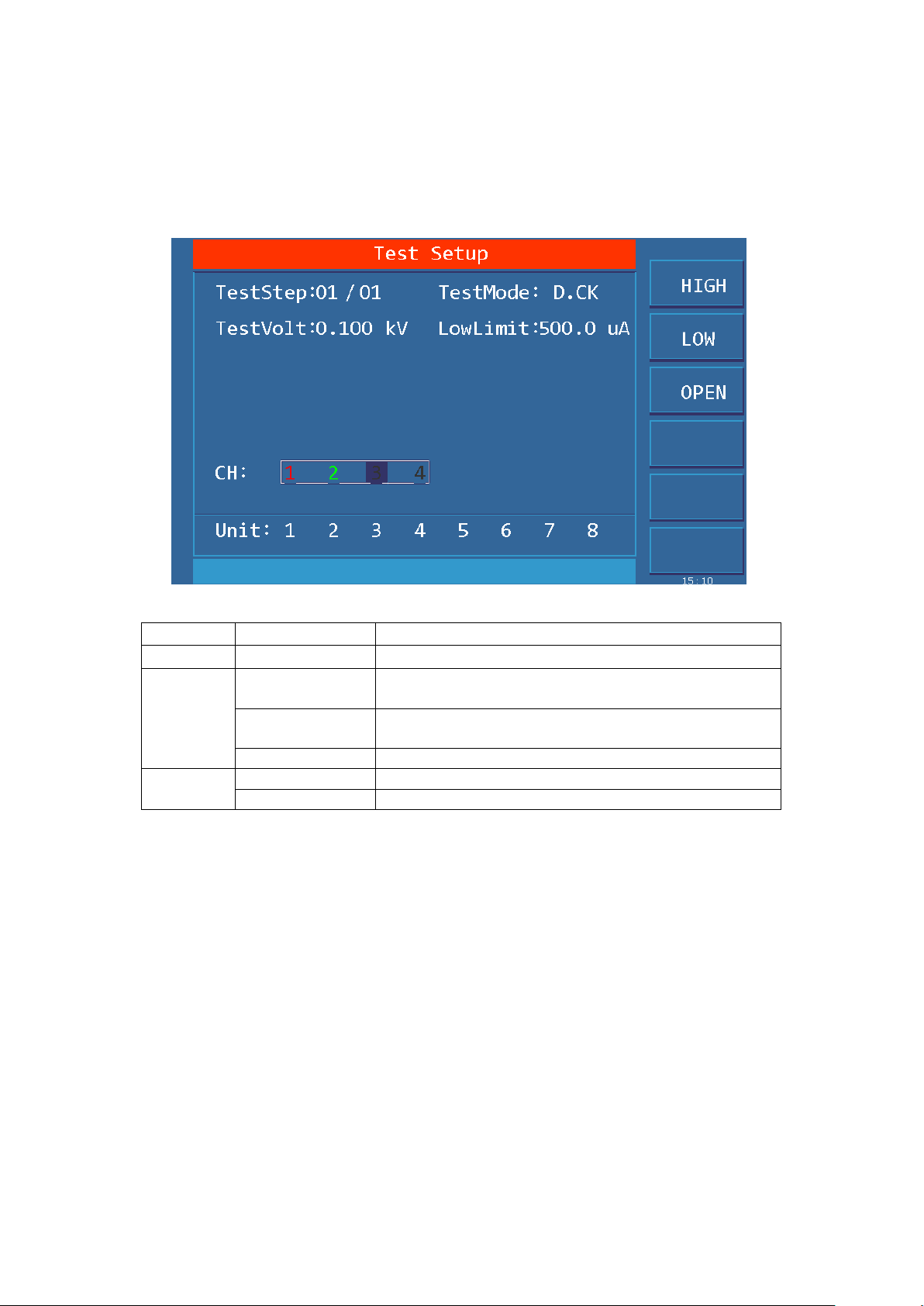
4.3.6 D.CK Double-ended contact check parameter setting
VOLT:
0.50~0.500kV
High voltage test voltage value.
UPPER:
0.1uA~5.00mA
Current upper limit.
SCAN:
Red
This port is connected to high voltage for contact
inspection.
Green
This port is connected to the test end for contact
inspection.
Gray
This port is open.
UNIT:
White
This unit participates in the test.
Gray
This unit does not participates in the test.
It is valid to connect multi-channel scan box.
D.CK Function: Is the two test leads with two scan ports connected reliably? Generally connected to
the same pin of the DUT, it can only be used with the scan controller.
The setting interface is as follows:
Figure 4.3.6 D.CK setting interface
Contact Check (D.CK) the test parameters are as follows:
Description:
1. The actual current is related to the internal resistance of the test loop. The default is the preferred
configuration
2. The test status is DC power open loop mode, setting parameters and test values are for reference
only
3. Can only achieve 1 pair of high and low end test at a time, after the test is over, the instrument
will automatically perform a rapid discharge of 0.2 seconds.
4. Total Test Time=0.7S
4.4 Test function principle and instructions for use
This section takes the test process in order; introduce the principle and use of ground connection,
ground current detection, arc detection and other tests.
◇36
Page 37
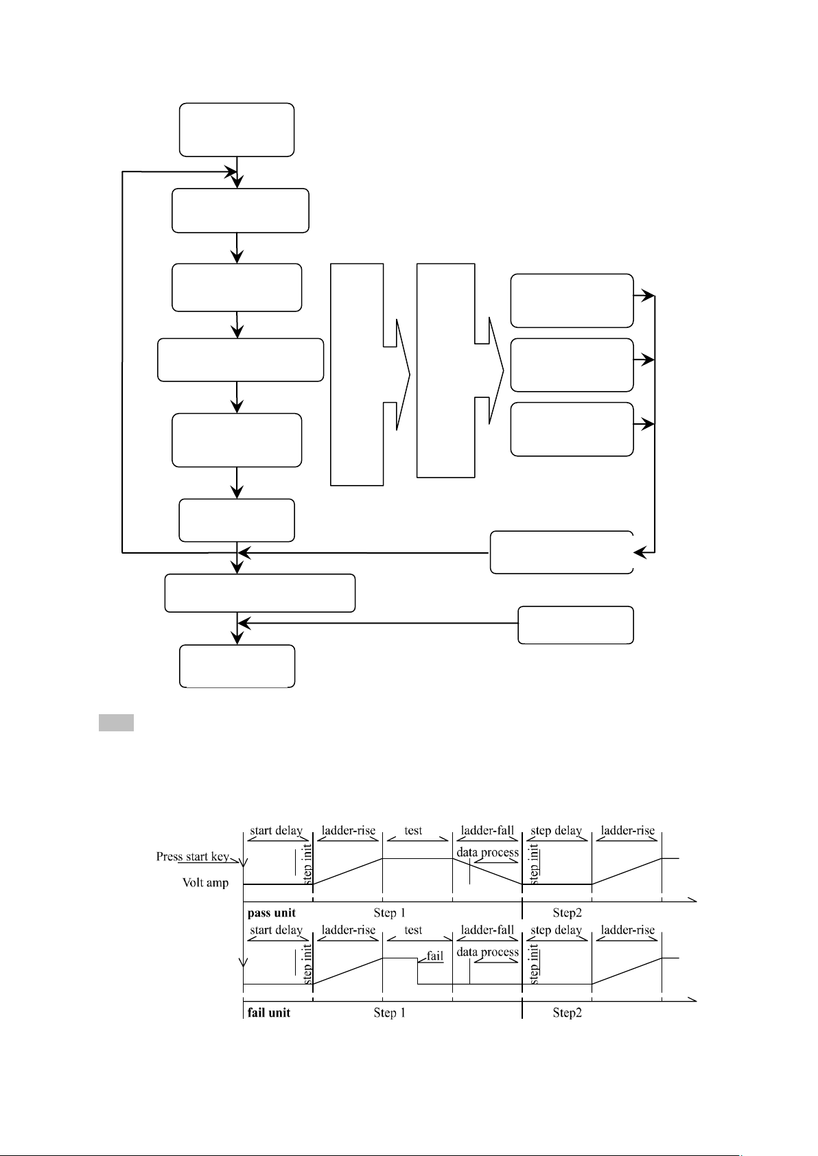
1. Start Test
5. HV Test
6.Voltage Fall
2. Test Delay
3. Voltage Rise
4. Charge current detection
7. Ground current
10. Test result processing
12. Test end
8. Arc detection
8. Current overrun
If there is any FAIL within this range, the
following FAIL judgment will be triggered
9. Unqualified treatment
Multistep
test
11. Stop
DC mode allows no treatment of
current overrun in WAIT time
Instrument test flow diagram
Note:
1. When FAIL appears in a test unit, test of this test unit ends, instrument indicates FAIL format.
2. The test of one step is ended when all test units are FAIL, or when the test process for testing other
test units ends.
3. At the end of the test step, if there is FAIL in the test unit, the next step of the instrument will be
determined according to the setting mode of FAIL.
◇37
Page 38

Instrument test timing diagram
4.4.1 Start Test
When the instrument is in test mode, check the test conditions and the connected parts are connected
correctly. Press the START button to start the test.
4.4.2 Test Delay
After the test is started, the delay before the first step is delayed according to the set delay time of the
system interface.The delay between multiple steps is delayed according to the items in the system
interface.
4.4.3 Voltage Rise
Some of the characteristics of the DUT are sensitive to sudden changes in voltage and require this
function.When the instrument starts to output, the output voltage is zero. When the voltage output
starts, the instrument will control the output voltage to step up in 0.1S. The step boost value is
determined according to the test voltage and voltage rise time (ΔV = V / (10 *). S)).If the voltage rise
time (RISE OFF) is turned off, the default voltage rise time is 0.1 second, and the test time is
automatically added, so that the test time minimum is 0.2S.If this value is too small, it may cause an
error in the ARC or DC boosting determination. Please note.
4.4.4 DC boost decision
Whether the current upper limit determination function switch is activated during voltage rise is
mainly used to avoid test misjudgment.
When the distribution capacitance is small, if the charging current of the capacitor is relatively small
and does not cause a significant change in the current, the opening of the boosting determination can
detect the poor performance of the DUT and reduce the probability of over current damage of the
component.
When the step capacitance is large, the capacitor will have a charging process during the voltage rise.
The current at this time may be much larger than the set upper limit of the measured current. If the
boost determination is turned on, the upper limit misjudgment will be caused.If necessary, turn on the
short-circuit threshold to reduce the short-circuit sensitivity and increase the charging current.
4.4.5 High Voltage Test
Perform high voltage test of the DUT. At this point, it should be possible to ensure that the test circuit
is correct, and the test results are not affected by some special accompanying parameters. The display
content is the actual withstand voltage and current required for the test.
4.4.6 Test Voltage Fall
As with the rise of the test voltage, it is determined by the characteristics of the DUT.When the high
voltage test ends, the voltage falls, the instrument will control the output voltage fall in 0.1S units (the
DC voltage will not decrease with the control voltage). The step-down value is determined according
to the test voltage and voltage rise time (ΔV = - V / (10). *S)).If the voltage drop time (FAIL OFF) is
turned off, the default voltage fall time is 0.1 second.At this time, the instrument does not make a test
comparison judgment, the data is for reference only.When the voltage fall is over, the instrument will
connect the test circuit to the AC withstand voltage mode. At this time, if the DC voltage falls, the
device will discharge through the AC circuit of the instrument.
4.4.7 Ground Current Detection Function
Ground current detection is to detect the current flowing through the instrument chassis to prevent
electric shock.When the high voltage is output, there is a current flowing from the voltage output
terminal through the human body to the instrument chassis, which may cause very serious
◇38
Page 39
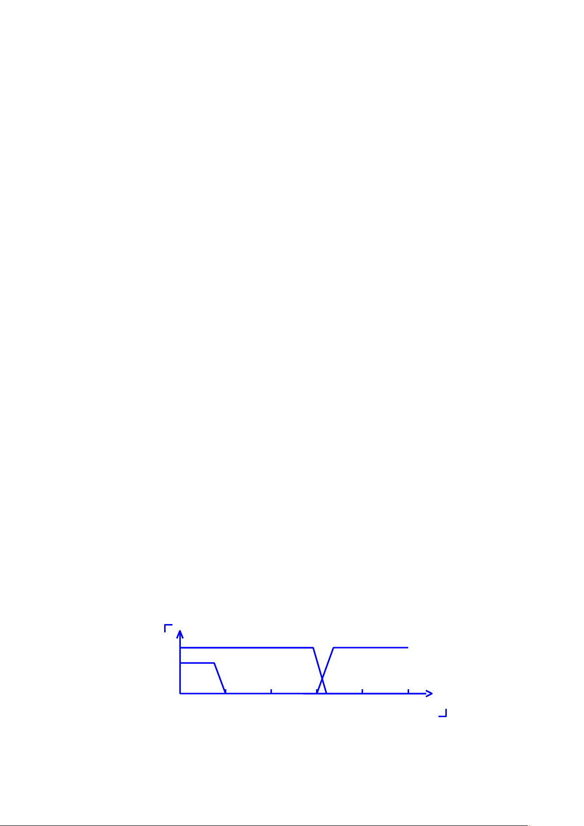
consequences.
10
100
1k
10k
100k
B
C
A
The instrument's ground current detection and judgment circuit response description:
When local line current detection is enabled, the ground current is greater than 0.45mA and the
ground current is over-limit.
When judging the electric shock, the instrument will end the high voltage output within 0.3S and
exit the test state.And display (GFI FAIL)
Note: The instantaneous output current of the instrument may be greater than 30 mA. If it is
indeed an electric shock, it may cause the operator to stun or die.Therefore, it is recommended
to turn on the ground current detection when the product allows.
4.4.8 Current Overrun and Arc Detection (ARC) Function
Current overrun classification: current lower limit, current upper limit, current overrun, arc detection.
Current lower limit judgment (LOW): Generally used as a test for low-end disconnection,
when the instrument is tested, the device will definitely have a certain leakage current, when the
leakage current of the instrument test is less than the lower limit set current value, it is considered
that the test fails (no device is connected), this function must be turned off if the measured
component itself has a small leakage current. Judgment display (LOW FAIL) when overrun, this
judgment is valid only in test mode, timed sampling, the rate is 100mS each time.
Current upper limit judgment (HIGH): Most commonly used test current overrun
judgment.When the instrument tests the equipment, the equipment will definitely have a certain
leakage current. When the leakage current of the instrument test is greater than the upper limit set
current value, it is considered that the equipment withstand voltage impedance is insufficient and
the test fails. Judgment display (HI FAIL) when overrun, this judgment is valid only in test mode,
timed sampling, the rate is 100mS each time.
Current limit determination: Since the current sampling is judged to be slow, when the
insulation collapses, the current changes rapidly, the sampling circuit cannot reflect in time, and
the current peak exceeds the allowable output range of the instrument, which will trigger such
over-limit judgment, Judgment display (SHORT FAIL) when overrun.Since the data cannot be
collected after such current exceeds the limit, the output of the system is: the test result within
100mS before the current exceeds the limit.The current limit is twice the allowable output current
of the instrument (1.5 times the peak value of AC).The fall time is invalid and this judgment
cannot be shielded.
Arc Detection (ARC): It is a very practical function for the measurement of coil components, it
tests the local current oscillation caused by the instantaneous discharge of the local circuit in the
high voltage test loop. Due to the superposition on the normal test current, the abrupt time is
short, and the above ordinary current detecting circuit cannot make an appropriate judgment in
response to the current change.The arc detection circuit filters out normal current values and only
processes high speed current pulse changes.Since the low-pass filtering and the size of the arc are
inherently random, this function can only estimate the extent of local sparking.Since the data
cannot be collected after the current exceeds the limit, the output result at this time is the last test
result when it is qualified. Judgment display (ARC FAIL) when overrun. ARC current test is
qualitative analysis, the amount of size and test environment, test line distribution, etc., effect
randomness is very large, pay attention when using.
Comparison of frequency response of current overrun judgment and arc detection: (See the picture
◇39
Page 40

above)
Area A in the figure: shows the circuit frequency response for current sampling. Because
it is necessary to filter the ripple of the power supply frequency → AD sampling →
calculate the test result → analyze whether the current exceeds the set limit. Within the
test current range, the pulse width is greater than 100mS.
Area B in the figure: current fast response circuit.It only filters out high-frequency
interference signals → voltage peak comparison → over-current peak signal lock, only
do limit judgment.Larger than the instrument allowed output current, pulse width greater
than 1mS.
Area C in the figure: arc detection circuit. The arc detection circuit only samples the
amplitude of the sudden change in the current, and the signal high-pass filter removes
the low frequency→voltage peak comparison→pulse lock. A sudden change edge in
current near the set value, and the pulse width is about 1uS-1mS.
4.4.9 Failure Judgment
1. When the current exceeds the maximum output current that the instrument can withstand, or the
instrument finds a safety hazard, the instrument will immediately cut off the voltage of the test
circuit and wait for the instrument software to check the cause of the error and judge the failure.
2. If the test result exceeds the limit set by the test item, the instrument will judge that the test piece
is unqualified. And immediately stop the current test, cut off the voltage output, and enter the
processing procedure that the test result is unqualified.
3. When testing in multiple steps, so long as there is a step FAIL, the total test result is FAIL.
4.4.10 Test Result Processing
If the test process exceeds the limit, it is judged as unqualified, there are many test items, and the
unqualified judgment processing mode is controlled by the system test mode. Otherwise, the
instrument will display the failure judgment and category, waiting for the user to process.
After the test is over, there is no unqualified mark, and the test result is judged as (PASS). The pass
judgment processing mode is controlled by SYSTEM PASS HOLD, and then ready to start the next
step measurement or return to the test wait state.
In a multi-step test, the control signal output of the system is controlled by the control mode. Select
FILE mode, then the test results will only be output when the entire file is tested. The end of the test
is controlled by the failure mode. See the system option description for details.
From this state until the next project starts high pressure start, customers can use software to
query test data and results.
4.4.11 STOP (Stop Measuring)
Press the STOP button in any state during the entire test, the instrument will automatically end the
test, and there will be no test results to judge the output when the test is finished.
At the end of the test, the customer can use the software to query the test data.
4.4.12 OFFSET (The base is cleared)
Prior to testing, due to changes in the instrument's operating environment and test cable placement,
some bases may appear during the instrument's no-load test. For customers who require accurate
◇40
Page 41
measurement, they can be cleared by the SYSTEM interface. The specific steps are as follows:
SCAN:
| 1 2 3 4 |
Connect 1 Scan Controller
Black
Open Circuit State
Red
It is connected to the high voltage end
Green
It is connected to test end
1. Set the current test conditions on the SETUP interface.
2. Select the OFFSET item in the SYSTEM screen and set it to ON.
3. Pressing GET will automatically start the high voltage test and zero the current test value.
4. If the customer does not set the test time, then the test can be stopped with the STOP
button.
Note:
Do not connect the product to the test terminal during GET. Clearing the product does not
improve the actual test range of the instrument.
4.5 SCAN multi-cell multi-channel scanning controller structure and use
The structure of the TH90101/A controller is the high voltage relay matrix. The withstand voltage
tester can directly control the matrix to realize the connection between the controller output and the
output of the withstand voltage tester.
The TH90101 controller has 8 sets of test unit inputs, each of which corresponds to 4 scan output
ports.
The TH90101A controller has 4 sets of test unit inputs, each of which corresponds to 4 scan output
ports.
The TH9010/A withstand voltage meter can control up to 4 controllers, enabling 4*4=16 scan ports
per test unit.
4.5.1 After adding multiple scan channels, the instrument will add
SCAN (multiple) parameters
The number in the parameter indicates the corresponding output channel, and the color indicates the
internal connection:
◇41
Page 42
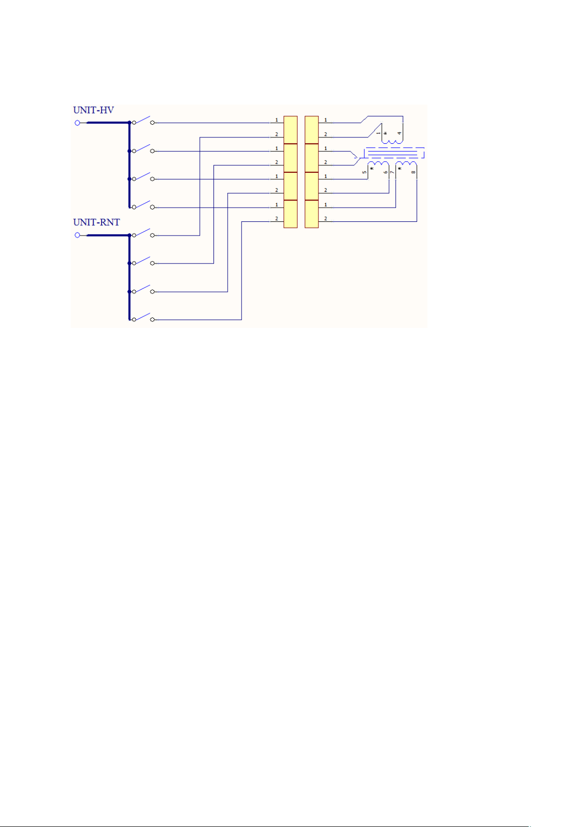
4.5.2 Structural principle
Description:
1. Multi-channel controller output port uses two-wire lead-out, can achieve single contact
inspection
2. The contact check is similar to the DCR test. It is tested whether the two wires of the same port
are connected. Due to the limited current resistance of the line itself, the test parameters are for
reference only.
3. When the contact is inspected, the two leads of the same port cannot be directly shorted. Can be
connected to different contacts of the same pin of the DUT; or two pins connected by resistors and
inductors (see illustration).
When the port is not used as a contact check, the two wires can be short-circuited and connected to
the DUT pin.
4.6 Structure and Use of HANDLER and SINGNAL Interface Circuit
4.6.1 Control Interface Theory
HANDLER interface and internal principle of SINGAL interface instrument. The interface signals are as
follows:
◇42
Page 43
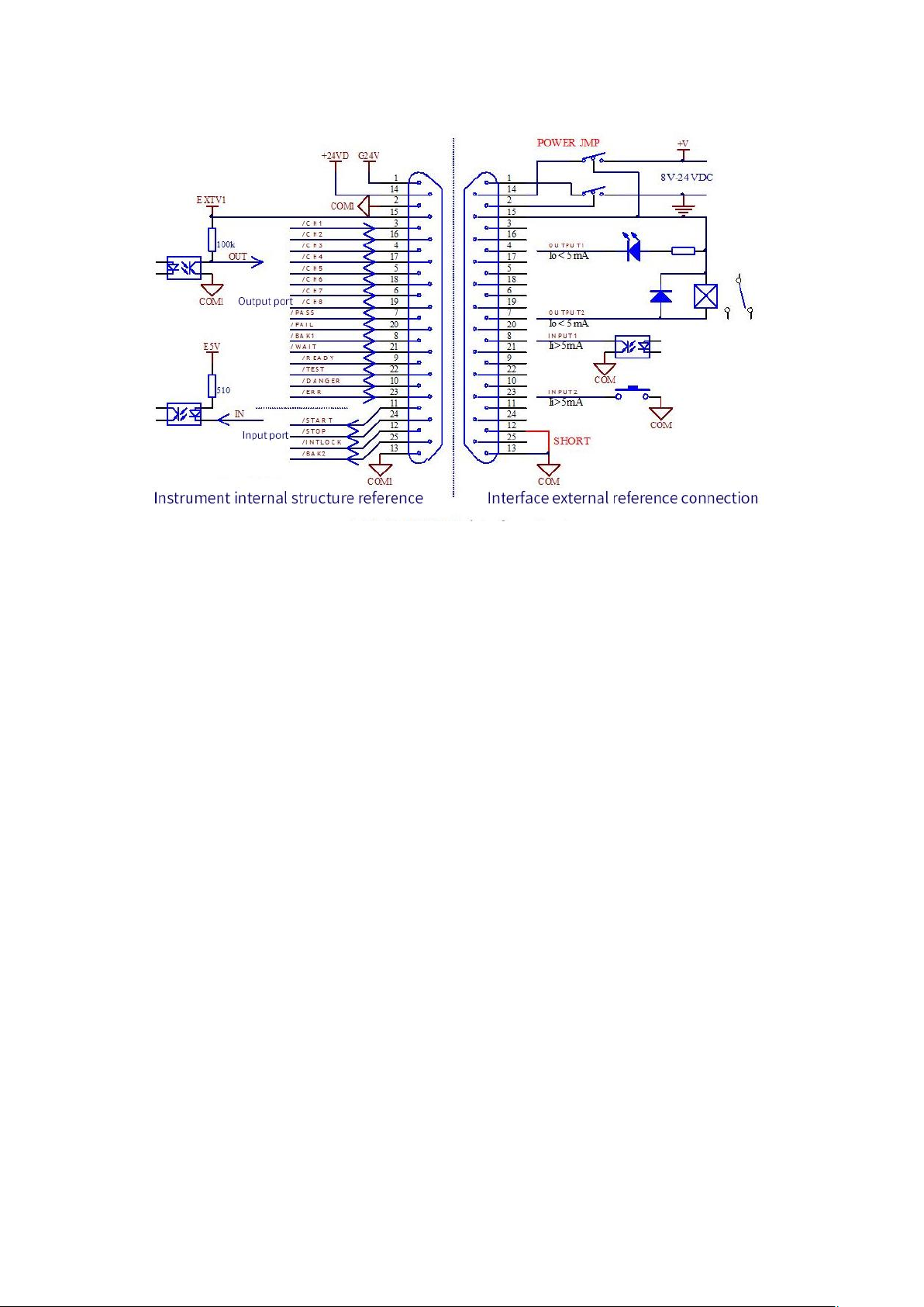
4.6.1 HANDLER interface structure
Description:
1. +24VD: +24Vdc power supply inside the instrument, COM1 at the low end. The output current is
200mA. When the POWER JMP is short-circuited, it provides a pull-up power supply for the output
optocoupler, and an external LED can also be used for indication.
2. EXTV1: The external input port controls the power supply, and the low end is COM1. This pin can
be connected to +24VD or an external 8-24V power supply. The internal current of the instrument is
<50mA. When this power supply is not connected, the output optocoupler is only the polar switch
signal (C/E pole current direction) on the secondary side of the optocoupler. The input signal of
the interface is invalid.
3. E5V: Instrument input optocoupler power supply, generated by EXTV1 regulation. Used to give the
input signal optocoupler power supply, the input signal is invalid when there is no such power supply.
4. INTLOCK: is the instrument online lock. The instrument cannot start the high voltage output
when disconnected here.
5. The START and STOP signals form a remote input control. Valid for shorting on COM1
6. The TEST, PASS, FAIL, and DANGER signals form a remote output control, and the optocoupler
pulls up the output signal. The specific effective state can be customized by the user, the default is
active low, and the optocoupler secondary side is turned on.
The instrument is equipped with TH9010-IL at the factory. The connection method is short-circuited
with the thick lead (POWER JMP) and (INTLOCK JMP) as shown above, and the other is left
floating.
4.6.2 HANDLER Control Interface Main Signal Timing Description
Control interfaces are typically used for remote control and test synchronization or indication. The
external connections of the interface are as follows:
◇43
Page 44
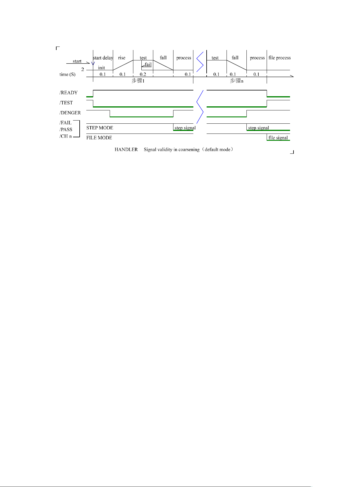
4.6.2 HANDLER interface timing diagram
4.7 File Storage Other interfaces and functions of the instrument
1. The USB DEV on the front panel is used to connect the USB flash drive for exporting and
importing customer settings files and upgrading the instrument software.
2. The rear panel USB HOST has two working modes for connecting to the computer:
USBTMC: Standard USB slave mode. Compatible with software format IEE488.
USBVCOM: USB analog serial port mode, data format: 8.n.1. Compatible with software format
IEE485.
3. RS232 is used to connect with the computer. The baud rate is shown in the system setting item, and
the data format is 8.n.1. It is compatible with software format IEE485.
◇44
Page 45

Chapter 5 Serial Port Commands Instruction
Brief Description of the Command Format:
1. The tester commands only describe the actual characters received or sent.
2. Command characters are all ASCII characters.
3. The data "<???>" of the command is an ASCII string. The default format of the system is
integer or floating point number. The default data unit does not appear in the commands.
4. The command end must have an command end tag, and the default end tag is:
a) NL: new line, an integer of 10 (0x0A). An identifier for the end of a command, without this, the
tester does not resolve the command.
b) ^END: EOI (end) signal of IEEE-488 bus.
Example of Multiple Commands to Simplify Sending:
FUNC:SOUR:STEP_1:AC:VOLT_1000;UPPC_1;TTIM_9.9;CH1_HIGH;CH2_LOW
(NL^END)
FUNC:SOUR:STEP_INS (NL^END)
FUNC:SOUR:STEP_2:DC:VOLT_1000;UPPC_1;TTIM_9.9;CH1_HIGH;CH2_LOW
(NL^END)
Note: In the above example, "_" is a space tag.
Subsystem commands of TH9010:
●DISPlay ●FUNCtion
●SYSTem ●MMEM ●FETC
5.1 DISPlay Subsystem Commands
DISPlay subsystem commands are mainly used to set the instrument display page.
The :DISPlay? query returns to the current page.
Command Syntax: DISPlay:PAGE <page name>
Command Tree:
DISPlay: PAGE MEASurement Set the display page to: measurement display page
MSETup Set the display page to: Measurement Setting Page
SYSTem Set the display page to: System Setting Page
FLISt Set the display page to: File List Page (FILE)
Command Syntax: DISPlay:PAGE <page name>
Query syntax: : DISPlay:PAGE?
Return format: <page name><NL^END>
<page name> details as below:
MEASurement Set the display page to: measurement display page
MSETup Set the display page to: Measurement Setting Page
SYSTem Set the display page to: System Setting Page
FLISt Set the display page to: File List Page (FILE)
5.2 MMEM Subsystem Commands
MMEM: STOR Store the current settings to a file stored internally as <filename>.
◇45
Page 46
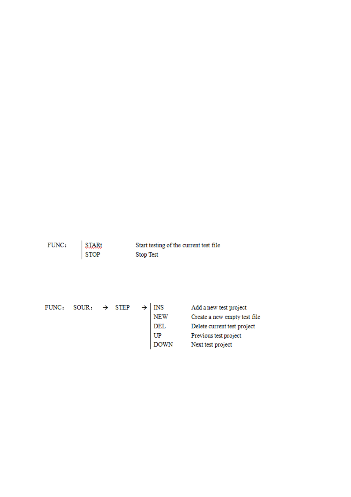
--Syntax:
Command messag: MMEM:STOR :STAT <file #>[,<file name>]
--Data<file #>:
Data format: Integer
Return Value: 1-20
Data accuracy: 1
--Data<file name>:[ ]Internal is negligible
Data format: characters
Return Value: 1-15
MMEM:LOAD LOAD the internal file specified by the file name to the current.
--Syntax:
Command message: MMEM:LOAD :STAT <file#>
--Data<file#>:
Data format: Integer
Return Value: 1-20
Data accuracy: 1
5.3 FUNCtion Subsystem Commands
5.3.1 FUNCtion test, Stop instruction
Commands:
5.3.2 FUNCtion File Editing Function Commands
Commands:
5.3.3 FUNCtion Test Function, Test Parameter Commands
Commands:
◇46
Page 47
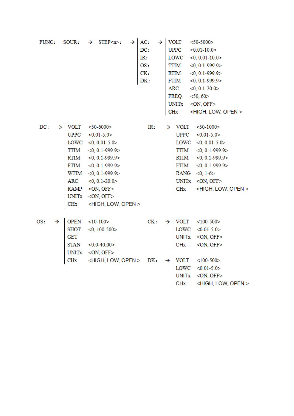
5.3.4 Specific Examples of Command Data Format
Commands for AC Setup Function
FUNC:SOURce:STEP <sn>:AC:VOLT To set / inquiry about the voltage for ACW test.
--Syntax:
Command message: FUNC:SOUR:STEP <sn>:AC:VOLT<voltage>
Query message: FUNC:SOUR:STEP <sn>:AC:VOLT?
--Data<sn>: (<sn> same below, no longer repeat)
Data format: integer
Data range: 1~20
Data accuracy: 1
◇47
Page 48

--Data<voltage>:
Data format: integer
Data range: 50~5000
Data accuracy: 1
Data unit: V
--Example:
Set the voltage for ACW test in STEP1 as 1000V.
Command message: FUNC:SOUR:STEP 1:AC:VOLT 1000
--Return Message:
Query message: FUNC:SOUR:STEP 1:AC:VOLT?, returns to the current ACW
voltage in STEP 1, such as 1000.
FUNC: SOURce:STEP:AC:UPPC To set/inquiry about the UPPER current for ACW test.
--Syntax:
Command message: FUNC:SOUR:STEP <sn>:AC:UPPC<current>
Query message: FUNC:SOUR:STEP <sn>:AC:UPPC?
--Data<current>:
Data format: float
Data range: 0.001 ~20.000 mA
Data accuracy: 0.001mA
Data unit: mA
--Example:
Set the upper current for ACW test in STEP1 as 1mA.
Command message: FUNC:SOUR:STEP 1:AC:UPPC 1
--Return Value:
Query message: FUNC:SOUR:STEP 1:AC:UPPC?
Return to the current limit of ACW in STEP 1, such as 1
FUNC:SOURce:STEP <sn>:AC:LOWC To set /inquiry about the LOWER current for ACW test.
(Syntax refer to AC:UPPC)
FUNC:SOURce:STEP <sn>:AC:TTIM To set /inquiry about the TEST time for ACW test.
--Syntax:
Command message:FUNC:SOUR:STEP <sn>:AC:TTIM <time>
Query message: FUNC:SOUR:STEP <sn>:AC:TTIM?
--Data<time>:
Data format: float
Data range: 0~999.9 (0 is OFF)
Data accuracy: 0.1s
Data unit: s
--Example:
Set the TEST time for ACW test in STEP1 as 1s.
Command message: FUNC:SOUR:STEP 1:AC:TTIM 1
--Return Value:
◇48
Page 49

Query message: FUNC:SOUR:STEP 1:AC:TTIM?
Return to the current test time of ACW in STEP 1, such as 1
FUNC:SOURce:STEP <sn>:AC:RTIM To set /inquiry about the RISE time for ACW test.
(Syntax refer to AC:TTIM)
FUNC:SOURce:STEP <sn>:AC:FTIM To set /inquiry about the FALL time for ACW test.
(Syntax refer to AC:TTIM)
FUNC:SOURce:STEP <sn>:AC:ARC To set /inquiry about the ARC upper current for ACW
test.
--Syntax:
Command message: FUNC:SOUR:STEP <sn>:AC:ARC<current>
Query message: FUNC:SOUR:STEP <sn>:AC:ARC?
--Data<current>:
Data format: float
Data range: 0~20.0 mA (0 is OFF)
Data accuracy: 0.1mA
Data unit: mA
--Example:
Set the ARC upper current for ACW test in STEP1 as 1mA.
Command message: FUNC:SOUR:STEP 1:AC:ARC 1
--Return Message:
Query message: FUNC:SOUR:STEP 1:AC:ARC?
Return to the ARC current upper limit of ACW in STEP 1, such as 1.000
FUNC:SOURce:STEP <sn>:AC:FREQ To set /inquiry about the test frequency for ACW test.
--Syntax:
Command message: FUNC:SOUR:STEP <sn>:AC:FREQ<frequency>
Query message: FUNC:SOUR:STEP <sn>:AC:FREQ?
--Data<frequency>:
Data format: character
Data range: 50/60
Data unit: Hz
--Example:
Set the test frequency for ACW test in STEP1 as 50Hz.
Command message: FUNC:SOUR:STEP 1:AC:FREQ:50
--Return Message:
Query message: FUNC:SOUR:STEP 1:AC:FREQ?
Return to the test frequency of ACW in STEP 1, such as 50.
FUNC:SOURce:STEP <sn>:AC:UNIT1 To set /inquiry about the multiple channels for ACW
test.
◇49
Page 50

--Syntax:
Command message: FUNC:SOUR:STEP <sn>:AC:UNIT1 <channel switch>
Query message: FUNC:SOUR:STEP <sn>:AC:UNIT1?
--Data<channel>:
Data format: character
Data range: ON/OFF (0/1)
--Example:
Set UNIT1 of ACW in STEP 1 to ON
Command message: FUNC:SOUR:STEP 1:AC:UNIT1 ON/1
--Return Message:
Query message: FUNC:SOUR:STEP 1:AC:UNIT1?
Return to the UNIT 1’s switch of ACW in STEP 1, such as ON
Note: Other channels are same, for example:
--Example:
Set UNIT2 of ACW in STEP 1 to OFF
Command: FUNC:SOUR:STEP 1:AC:UNIT2 OFF/0
--Return Message:
Query message: FUNC:SOUR:STEP 1:AC:UNIT2?
Return to the UNIT 2’s switch of ACW in STEP 1, such as OFF
FUNC:SOURce:STEP <sn>:AC:CH1 To set /inquiry about the scan box for ACW test.
--Syntax:
Command message: FUNC:SOUR:STEP <sn>:AC:CH1 <scan method>
Query message: FUNC:SOUR:STEP <sn>:AC:CH1?
--Data<scan method>:
Data format: character
Data range: HIGH/LOW/OPEN
--Example:
Set CH1 of ACW in STEP 1 as HIGH
Command message: FUNC:SOUR:STEP 1:AC: CH1 HIGH
--Return Message:
Query message: FUNC:SOUR:STEP 1:AC: CH1?
Return to CH1 of ACW in STEP 1, such as HIGH
Note: Other scan methods are same, for example:
--Example:
Set CH2 of ACW in STEP 1 as LOW
Command message: FUNC:SOUR:STEP 1:AC: CH2 LOW
--Return Message:
Query message: FUNC:SOUR:STEP 1:AC: CH2?
Return to CH2 of ACW in STEP 1, such as LOW
◇50
Page 51

Commands for DC Setup Function
FUNC:SOURce:STEP <sn>:DC:WTIM To set /inquiry about the wait time for DCW test.
(Syntax refer to AC:TTIM)
FUNC:SOURce:STEP <sn>:DC:RAMP To set/query the ramp state of DCW.
--Syntax:
Command message:
FUNC:SOUR:STEP <sn>:DC:RAMP:<ON/OFF> or <1/0>
Query message:
FUNC:SOUR:STEP <sn>:DC:RAMP:?
--Example:
Set the status of RAMP of DCW in STEP 1 as:ON
Command message: FUNC:SOUR:STEP 1:DC:RAMP ON
--Return Message
Query message: FUNC:SOUR:STEP 1:DC:RAMP?
Return to RAMP status of DCW in STEP 1, such as ON
Commands for IR Setup Function
FUNC:SOURce:STEP <sn>:IR:UPPC To set /inquiry about the UPPER resistance for
IR test.
--Syntax:
Command message:FUNC:SOUR:STEP <sn>:IR:UPPC <resistance >
Query message:FUNC:SOUR:STEP <sn>:IR:UPPC?
--Data< resistance>:
Data format: float
Data range: 0, 0.1~10000MΩ (0 is OFF)
Data accuracy: 0.1 MΩ
Data unit: MΩ
--Example:
Set the upper resistance for IR test in STEP1 to 1 MΩ.
Command message: FUNC:SOUR:STEP 1:IR:UPPC 1
--Return Message:
Query message: FUNC:SOUR:STEP 1:IR:UPPC
Return to upper limit of IR in STEP 1, such as 1
FUNC:SOURce:STEP <sn>:IR:LOWC To set /inquiry about the LOWER resistance for IR
test.
(Syntax refer to IR:UPPC)
FUNC:SOURce:STEP <sn>:IR:RANG To set /inquiry about the RANG for IR test.
--Syntax:
Command message: FUNC:SOUR:STEP <sn>:IR:RANG <rang>
Query message: FUNC:SOUR:STEP <sn>:IR:RANG?
◇51
Page 52

--Data<range>:
Data Format: Integer
Data Range: 0~6 (0 is AUTO, 1 is 5mA, 2 is 1mA, 3 is 100uA,
4 is 10uA, 5 is 1Ua, 6 is 0.1uA,)
--Example:
Set the range for IR test in STEP 1 to: 5mA
Command message: FUNC:SOUR:STEP 1:IR: RANG 1
--Return Message:
Query message: FUNC:SOUR:STEP 1:IR: RANG?
Return to test range of IR in STEP 1, such as 1
Commands for OS Setup Function
FUNC:SOURce:STEP <sn>:OS:OPEN To set /inquiry about the OPEN rate for OS test.
--Syntax:
Command message: FUNC:SOUR:STEP <sn>:OS:OPEN<rate>
Query message: FUNC:SOUR:STEP <sn>:OS:OPEN?
--Data<rate>:
Data format: integer
Data range: 10~100
Data accuracy: 1
--Example:
Set the OPEN rate for OS test in STEP1 as 50%.
Command message: FUNC:SOUR:STEP 1:OS:OPEN 50
--Return Message:
Query message: FUNC:SOUR:STEP 1:OS:OPEN?
Return value: 50
FUNC:SOURce:STEP <sn>:OS:SHOT To set /inquiry about the SHOT rate for OS test.
--Syntax:
Command message: FUNC:SOUR:STEP <sn>:OS:SHOT<rate>
Query message: FUNC:SOUR:STEP <sn>:OS:SHOT?
--Data< rate>:
Data format: integer
Data range: 0~500 (0 is OFF)
Data accuracy: 10
--Example:
Set the SHOT rate for OS test in STEP1 as 100%.
Command message: FUNC:SOUR:STEP 1:OS: SHOT 100
--Return Message:
Query message: FUNC:SOUR:STEP 1:OS: SHOT?
Return value: 100
FUNC:SOURce:STEP:OS:STAND To set /inquiry about the STANDARD capacitance for OS
test.
◇52
Page 53
--Syntax:
Command message: FUNC:SOUR:STEP <sn>:OS:STAND<capacitance >
Query message: FUNC:SOUR:STEP <sn>:OS: STAND?
--Data< capacitance >:
Data format: float
Data range: 0.001 ~40.0nF
Data accuracy: 0.001nF
Data unit: nF
--Example:
Set the standard capacitance for OS test in STEP1 to 1nF.
Command message: FUNC:SOUR:STEP 1:OS:STAND 1
--Return Message:
Query message: FUNC:SOUR:STEP 1:OS: STAND?
Return value: 1.000
FUNC:SOURce:STEP <sn>:OS:GET Get current channel data as standard value.
Note: The instrument will initiate an OS test to get the current port value as a standard.
Please confirm that the port and test loop are configured correctly and pay attention to the
test safety.
Commands for CK Setup Function
FUNC:SOURce:STEP <sn>:CK:CH1 To set/ query CK scan box.
(There are only two states for CHx at CK.)
--Syntax:
Command message: FUNC:SOUR:STEP <sn>:CK:CH1<scan type >
Query message: FUNC:SOUR:STEP <sn>:CK:CH1?
--Data< scan type >:
Data format: character
Data range: ON/OFF(1/0)
--Example:
Set CH1 of CK in STEP 1 to ON
Command message: FUNC:SOUR:STEP 1:CK: CH1 1
--Return Message:
Query message: FUNC:SOUR:STEP 1:CK: CH1?
Return value: ON
Note:
The CK function is used to check if the two leads are connected between the same test end.
The instrument automatically detects step by step when detecting multiple test ends.
Commands for DK Setup Function
FUNC:SOURce:STEP <sn>:DK:CH1 To set/ query DK scan box
--Syntax:
Command message: FUNC:SOUR:STEP <sn>:DK:CH1<scan type >
Query message: FUNC:SOUR:STEP <sn>:DK:CH1?
◇53
Page 54
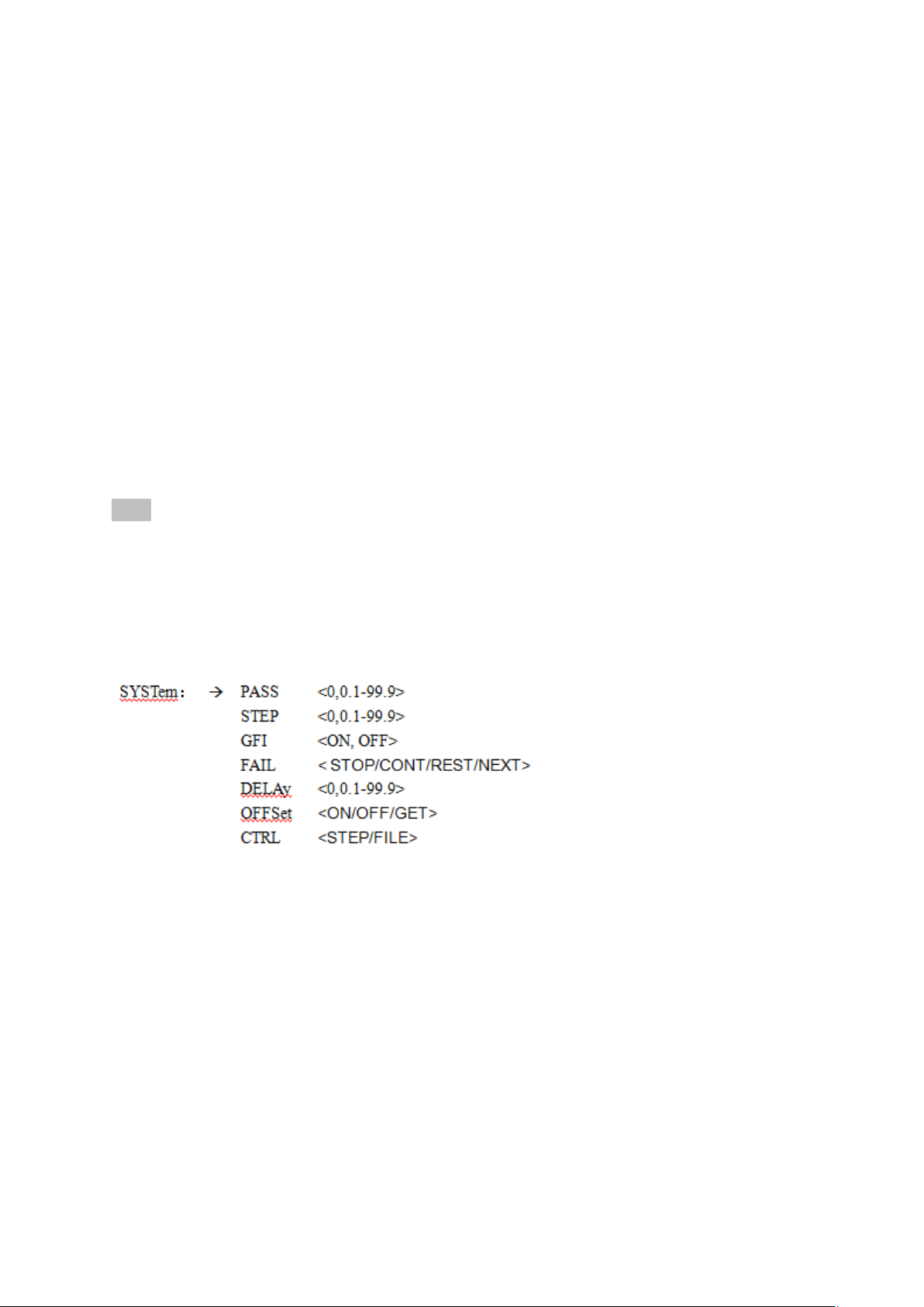
--Data< scan type >:
Data format: character
Data range: HIGH/LOW/OPEN
--Example:
Set CH1 of DK in STEP 1 to ON
Command message:FUNC:SOUR:STEP 1:DK: CH1 HIGH
--Return Message:
Query message: FUNC:SOUR:STEP 1:DK: CH1?
Return value: HIGH
Note: Other scanning equivalents, for example:
--Example:
Set CH2 of DK in STEP 1 to OFF
Command message:FUNC:SOUR:STEP 1:DK: CH2 HIGH
--Return Message:
Query message: FUNC:SOUR:STEP 1:DK: CH2?
Return value: HIGH
Note:
1. The DK function is used to check whether the two test terminals are connected. It is necessary to
set one channel to be connected high, and one channel to be low to form a loop.
DK detection must be performed separately when multiple loops occur, otherwise it will be missed.
5.4 SYSTem Subsystem Commands
Commands:
SYSTem: PASS To set/ query the time of PASSHOLD
--Syntax:
Command message: SYST:PASS<time>
Query message: SYST:PASS?
--Data:
Data format: float
Data range: 0~99.9
Data accuracy: 0.1
Data unit: s
--Example:
Set PASSHOLD to 1.0s
Command message:SYST:PASS 1
◇54
Page 55

--Return Message:
Query message: SYST:PASS?
Return value: 1.000.
SYSTem:STEP To set/ query the intervals of PASSHOLD (please refer : SYST:PASS)
SYSTem:GIF To set /query about the status for GFI.
--Syntax:
Command message: SYST:GFI <ON/OFF> or <1/0>
Query message: SYST:GFI?
--Data<ON/OFF>
Data format: character
Data range: 0 (OFF), 1 (ON)
--Example:
Set GR CONT as ON
Command message:SYST:GFI ON or:SYST:GFI :1
--Return Message:
Query message: SYST: GFI?
Return value: 1
SYSTem:FAIL To set /query about the state for AFTR FAIL.
--Syntax:
Command message: SYST:FAIL <0/1/2>
Query message:SYST:FAIL?
--Data< STOP/CONT/PAUS>
Data format: character
Data range: 0~3
--Example:
Set AFTR FAIL as STOP
Command message:SYST:FAIL 0
--Return Message:
Query message: SYST: FAIL?
Return value: 0
SYSTem:DELAy To set /inquiry about the test delay time. (please refer : SYST:PASS)
SYSTem:OFFSet To set /inquiry about the offset status.
--Syntax:
Command message: SYST: OFFS<ON/OFF/GET> or <1/0/G
Query message:SYST: OFFS?
--Data<ON/OFF/GET>:
Data format: character
Data range: 0 (OFF), 1 (ON), GET (get offset value)
◇55
Page 56

--Example:
Set OFFS as ON
Command message: SYST: OFFS ON or:SYST: OFFS 1
--Return Message:
Query message: SYST: OFFS?
Return value: 1
--Get the current value directly:
Command message: SYST: OFFS GET
5.5 Other Commands
*IDN Query instrument model, version information
Return Value: <manufacturer>, <model>, <firmware> <NL^END>
Here:
<manufacturer> name (Tonghui)
<model> model (such asTH9010)
<firmware> firmware version (such as Version1.0.0)
For example: WrtCmd (“*IDN?”);
FETCh To fetch the measurement results
--Syntax:
Command message: FETCh:AUTO <ON/OFF> or <1/0>
Query message: FETCh?
--Data<ON/OFF> or <1/0>:
Data format: character
Data range: 0 (OFF), 1 (ON)
--Example:
To set automatically return the test data to ON
Command message:FETCh:AUTO ON or: FETCh:AUTO 1
--Return Message:
Query message: FETCh? Return to the result of the current measurement of the instrument.
Command: FETCh?
After the instrument receives this command, the instrument will automatically send out the
test results until the end of the test.
Return format:
Step:test project:test unit,test voltage(V),test current(mA),sorting result;
⑴ ⑴ ⑵ ⑵ ⑵ ⑶
⑴:The separator between the step and the project, between the project and the unit test
data is (:)
⑵:The separator between the unit test data is (,). The separator between different unit
data is (;)
⑶:The separator between steps is (; + space). The data terminator defaults to (0x0A).
Note:
1. All data is an integer or floating point number. The default unit is the same as the FUNC
◇56
Page 57

instruction set.
2. All characters are ASCII characters
For example: turn on UNIT1, UNIT3.
All test results are STEP1:AC:1000V, test current 1mA, PASS.
STEP2:IR: 500V, test IR 100M, PASS.
Returned data format:
STEP1:AC:1, 1000, 1.000, PASS; 3, 1000, 1.000, PASS; (SPACE)
STEP2:IR:1, 500, 100.000, PASS; 3, 500, 100.000, PASS (0x0A)
◇57
Page 58
1. Specific parameters
Model
TH9010 series single channel parameters
Withstanding voltage test
Output
Voltage
AC
range
0.050kV—5.000kV
waveform
Sinusoidal Wave
distortion
< 3%
frequency
50, 60Hz selectable
accuracy
±1%
Output power
50VA (5.000kV 10mA)
Voltage
regulation
±(1.0% +50V) (rated power)
DC
range
0.050 kV—6.00kV
Source frequency
600Hz
Output power
25VA (5.000kV 5mA)
Voltage
regulation
± (1.0% +100V) (rated power)
Voltage resolution
1V
Voltage output accuracy
± (2.0% reading+5V) (no load)
Voltage generation method
DDS signal source plus PWM amplifier
Current
test range
AC
Current range
0.001mA – 10mA
SC current
(moment)
>20 mA
(setted output voltage >500V)
Current
resolution
0.001 mA
Current accuracy
± (2% reading +5 digits)
Actual current
OFF-0.001 mA-10mA
DC
Current range
0.1uA – 5.00mA
Current accuracy
± (2.0% reading +5 digits)
Discharge Function
Automatic discharge after the test (DCW)
IR Test
Output Voltage
0.050V – 1.000V
Voltage Resolution
1V
Voltage Accuracy
± (1.0% range+5V)
Max. Output Current
5mA
Max. Output Power
5VA (1000V/5mA)
Output instantaneous short circuit
current
>10mA (Setted output voltage>500V)
Load Adjustment Rate
≤1% (rated power)
Ripple(1kV)
≤3% (1kV, no load)
Chapter 6 Appendix
◇58
Page 59
Discharge Function
Automatic discharge after the test
Resistance Test Range
0.02MΩ– 10GΩ
Resistance display range
5mA 0.2 MΩ-1 MΩ
(1000V)
1mA 1 MΩ-10 MΩ
100uA 10 MΩ-100 MΩ
10uA 100 MΩ-1GΩ
1uA 1GΩ-10GΩ
Accuracy of resistance measurement
≥500V
1MΩ– 100MΩ ±(5% range +5 digits)
100MΩ– 10GΩ±(10% range+5 digits)
< 500V
0.1MΩ– 100MΩ±(10% range+5 digits)
1GΩ– 10GΩ for reference only no precision requirement
Accuracy of current measurement
±(2% range +5 digits) (After clearing)
ARC Detection
Test
AC
1mA – 20mA
Range
DC
1mA – 20mA
Comparator
Judgment method
Window comparison mode
I
low
ON: when I
low
< Ix < I
upper
, PASS; when I
x
≤ I
lower
or I
x
≥
I
upper
, FAIL (condition I
lower
< I
upper
)
I
low
OFF: when Ix < I
upper,
PASS; when I
x
≥ I
upper
,
FAIL
The insulation resistance discrimination method is the same as
the above.
Current upper limit
setting
AC
0.001mA – 10mA
DC
0.1uA – 5mA
Current lower limit
setting
AC
0.001mA – 10mA
(LOWER OFF)
DC
0.1uA –5mA
Resistance upper limit setting
OFF - 0.1MΩ - 10GΩ
Lower Resistance Limit Setting
0.01MΩ– 10GΩ (The minimum actual current of the lower
limit shall not be greater than 5mA)
Discriminant output
PASS/FAIL LCD and LED display respectively, sound alarm
Parameter Setting
Voltage rise time
0.1s – 999.9s
Voltage fall time
0s – 999.9s, (Effective only after voltage withstanding
PASS)
◇59
Page 60
Voltage waiting time
0.3s – 999.9s (Only DC withstand voltage, and meet (rise
time < wait time < (rise time + test time) )
Test time setting
0.3s – 999.9s (at TIMER ON)
Time Accuracy
± (0.2% set value+ 0.1s)
Measuring Function
Keyboard lock
Prevent accidental modification of test conditions or prohibit
modification of test conditions
Base Clearing Function
Current flowing through insulation resistance and distributed
capacitance between output lines can be cleared
Start Wait Delay
At the beginning of the test (press START), output the
high-voltage start signal, wait for a certain time, then start the
high-voltage output.
Judgment of Current Overrange
The hardware quickly judges the insulation collapse, which is
faster and safer than voltage sampling, reducing the impact
damage to the product.
ARC Detection
Abrupt signal of sampling current, to determine the potential
hidden dangers of the loop and the approximate scale
Ground current detection
Protect personal safety in case of accidental electric shock or
leakage of high voltage to the outer shell
Alarm volume adjustment
OFF, High, Low
High Voltage Indication
Window Indicator and LED Light Indicator
Storage and Interface
File Programming and Storage
Programmable 20 test files, 16 test steps can be set for AC, DC
and insulation resistance in each file.
USB Interface
Yes
Boot parameter saving
The setting parameters are saved as default parameters, which
can be automatically restored after the next boot.
Control interface
HANDLER, SINGAL
Communication interface
RS232C, USB
ACW
DCW
IR
OS
Test Unit
Scanning Module
S.CK
D.CK
TH9010
*
*
*
*
8channels
TH90101
*
*
TH9010A
*
*
*
*
4channels
TH90101A
*
*
2. Model function correspondence table
Each scanning module provides four scanning channels for each unit and up to four scanning
modules can be connected.
S.CK and D.CK are dedicated functions of the scanning module.
◇60
Page 61
General Technical Indicators
General technical indicators
Ambient Temperature and Humidity
0C-40C, 80%RH
Power
100V-242V 47.5-63Hz
Power consumption
≤1200VA
Dimension
TH9010
340mm×120mm×450mm
TH9010A
340mm×120mm×450mm
Weight
TH9010
About 40kg
TH9010A
About 25kg
◇61
 Loading...