

Tonghui TH2883-5, TH2883-10, TH2883 Series Operation Manual

TH2883 Series Operation Manual Version:1.0.1
1
O p e r a t i o n Ma n u a l
M
M
M
O
O
O
D
D
D
E
E
E
L
L
L
T
T
T
H
H
H
2
2
2
8
8
8
8
8
8
3
3
3
-
-
-
5
5
5
/
/
/
-
-
-
1
1
1
0
0
0
I
I
I
m
m
m
p
p
p
u
u
u
l
l
l
s
s
s
e
e
e
W
W
W
i
i
i
n
n
n
d
d
d
i
i
i
n
n
n
g
g
g
T
T
T
e
e
e
s
s
s
t
t
t
e
e
e
r
r
r
T
T
T
o
o
o
n
n
n
g
g
g
h
h
h
u
u
u
i
i
i
E
E
E
l
l
l
e
e
e
c
c
c
t
t
t
r
r
r
o
o
o
n
n
n
i
i
i
c
c
c
s
s
s
C
C
C
o
o
o
.
.
.
,
,
,
L
L
L
t
t
t
d
d
d
.
.
.
A
A
A
d
d
d
d
d
d
r
r
r
e
e
e
s
s
s
s
s
s
:
:
:
N
N
N
O
O
O
.
.
.
3
3
3
,
,
,
T
T
T
i
i
i
a
a
a
n
n
n
S
S
S
h
h
h
a
a
a
n
n
n
R
R
R
o
o
o
a
a
a
d
d
d
,
,
,
X
X
X
i
i
i
n
n
n
B
B
B
e
e
e
i
i
i
D
D
D
i
i
i
s
s
s
t
t
t
r
r
r
i
i
i
c
c
c
t
t
t
,
,
,
C
C
C
h
h
h
a
a
a
n
n
n
g
g
g
z
z
z
h
h
h
o
o
o
u
u
u
,
,
,
J
J
J
i
i
i
a
a
a
n
n
n
g
g
g
s
s
s
u
u
u
,
,
,
C
C
C
h
h
h
i
i
i
n
n
n
a
a
a
T
T
T
E
E
E
L
L
L
:
:
:
(
(
(
0
0
0
5
5
5
1
1
1
9
9
9
)
)
)
8
8
8
5
5
5
1
1
1
3
3
3
2
2
2
2
2
2
2
2
2
2
2
2
,
,
,
8
8
8
5
5
5
1
1
1
1
1
1
3
3
3
3
3
3
4
4
4
2
2
2
F
F
F
A
A
A
X
X
X
:
:
:
(
(
(
0
0
0
5
5
5
1
1
1
9
9
9
)
)
)
8
8
8
5
5
5
1
1
1
0
0
0
9
9
9
9
9
9
7
7
7
2
2
2
E
E
E
M
M
M
A
A
A
I
I
I
L
L
L
:
:
:
s
s
s
a
a
a
l
l
l
e
e
e
s
s
s
@
@
@
t
t
t
o
o
o
n
n
n
g
g
g
h
h
h
u
u
u
i
i
i
.
.
.
c
c
c
o
o
o
m
m
m
.
.
.
c
c
c
n
n
n
H
H
H
t
t
t
t
t
t
p
p
p
:
:
:
/
/
/
/
/
/
w
w
w
w
w
w
w
w
w
.
.
.
t
t
t
o
o
o
n
n
n
g
g
g
h
h
h
u
u
u
i
i
i
.
.
.
c
c
c
o
o
o
m
m
m
.
.
.
c
c
c
n
n
n

TH2883 Series Operation Manual Version:1.0.1
2
Contents
Chapter 1 Overview ........................................................................................................................ 1-1
1.1 Production introduction .................................................................................................... 1-2
1.2 Operation environment ..................................................................................................... 1-3
1.2.1 Power supply .......................................................................................................... 1-3
1.2.2 Environment temperature and humidity ................................................................ 1-3
1.2.3 Warm-up ................................................................................................................ 1-3
1.3 Dimensions and weight .................................................................................................... 1-3
Chapter 2 General specifications .................................................................................................... 2-1
2.1 Specifications ................................................................................................................... 2-1
2.2 Comparison methods ........................................................................................................ 2-2
2.2.1 Area size comparison ............................................................................................. 2-2
2.2.2 Differential area comparison .................................................................................. 2-2
2.2.3 Corona discharge comparison ................................................................................ 2-3
2.2.4 Differential phase comparison ............................................................................... 2-4
Chapter 3 Panels and display .......................................................................................................... 3-1
3.1 Front panel ....................................................................................................................... 3-1
3.2 Rear panel ......................................................................................................................... 3-3
3.3 Introduction to display area .............................................................................................. 3-4
Chapter 4 Introduction to [DISP] .................................................................................................... 4-1
4.1 Measurement display page ............................................................................................... 4-1
4.2 Introduction to symbols in measurement display page .................................................... 4-1
4.3 Introduction to soft keys in measurement display page ................................................... 4-2
4.3.1 Standard sampling .................................................................................................. 4-2
4.3.2 Compare ................................................................................................................. 4-3
4.3.3 Measure .................................................................................................................. 4-4
4.3.4 Utility ..................................................................................................................... 4-5
4.3.5 Statistics ................................................................................................................. 4-6
4.3.6 Modify ................................................................................................................... 4-6
Chapter 5 Introduction to [SETUP] ................................................................................................ 5-1
5.1 Introduction to icons of soft keys ..................................................................................... 5-1
5.2 Measurement setup page .................................................................................................. 5-1
5.2.1 Imp Volt ................................................................................................................. 5-2
5.2.2 Samp ...................................................................................................................... 5-2
5.2.3 Test Imp ................................................................................................................. 5-3
5.2.4 Erase Imp ............................................................................................................... 5-3

TH2883 Series Operation Manual Version:1.0.1
3
5.2.5 Volt ADJ ................................................................................................................. 5-3
5.2.6 Wave Disp .............................................................................................................. 5-3
5.2.7 Trig Mode .............................................................................................................. 5-4
5.2.8 Delay Time ............................................................................................................. 5-4
5.2.9 BDV Test ............................................................................................................... 5-5
5.2.10 Start Volt .............................................................................................................. 5-5
5.2.11 End Volt ................................................................................................................ 5-5
5.2.12 Volt Step ............................................................................................................... 5-6
5.2.13 Comparator .......................................................................................................... 5-6
5.2.14 Position (AREA SIZE, DIFF ZONE, PHASE DIFF) .......................................... 5-6
5.2.15 Position(PHASE DIFF) .................................................................................. 5-6
5.2.16 DIFF(Limit)(AREA SIZE, DIFF ZONE, PHASE DIFF) ............................ 5-7
5.2.17 DIFF(Limit)(CORONA) ............................................................................. 5-7
5.3 Int. File ............................................................................................................................. 5-7
5.4 Ext. File ............................................................................................................................ 5-9
Chapter 6 Introduction to [SYSTEM]............................................................................................. 6-1
6.1 System .............................................................................................................................. 6-1
6.1.1 Brightness .............................................................................................................. 6-2
6.1.2 Pass/Fail ................................................................................................................. 6-2
6.1.3 Pass Alarm ............................................................................................................. 6-2
6.1.4 Fail Alarm .............................................................................................................. 6-2
6.1.5 Key Sound .............................................................................................................. 6-2
6.1.6 Hard Copy .............................................................................................................. 6-3
6.1.7 Password ................................................................................................................ 6-3
6.1.8 Language ................................................................................................................ 6-3
6.1.9 Theme .................................................................................................................... 6-3
6.1.10 Date ...................................................................................................................... 6-4
6.1.11 Time ..................................................................................................................... 6-4
6.2 Interface ............................................................................................................................ 6-4
6.2.1 I/O .......................................................................................................................... 6-5
6.2.2 TH2883 RS232C interface ..................................................................................... 6-5
6.2.3 USB interface ......................................................................................................... 6-7
6.2.4 LAN interface ........................................................................................................ 6-9
6.3 About .............................................................................................................................. 6-11
Chapter 7 User guide ...................................................................................................................... 7-1
7.1 Use of keys ....................................................................................................................... 7-1
7.1.1 Use of the roller ..................................................................................................... 7
-1
7.1.2 Switch the display page ......................................................................................... 7-1
7.1.3 Numeric arrow key ................................................................................................ 7-1

TH2883 Series Operation Manual Version:1.0.1
4
7.2 Basic measurement ........................................................................................................... 7-2
7.2.1 Non-standard test ................................................................................................... 7-2
7.2.2 Sample test for standard wave ............................................................................... 7-2
7.3 BDV test ........................................................................................................................... 7-2
7.4 Technology application .................................................................................................... 7-3
7.4.1 Test objects ............................................................................................................. 7-3
7.4.2 Select comparison method ..................................................................................... 7-3
7.4.3 Settings of comparison method .............................................................................. 7-4
7.4.4 Select standards ...................................................................................................... 7-4
7.4.5 Chart for differential area ....................................................................................... 7-4
Chapter 8 Command reference ....................................................................................................... 8-1
8.1 Command structure .......................................................................................................... 8-1
8.2 Notation conventions and definitions ............................................................................... 8-3
8.3 Command reference ......................................................................................................... 8-3
8.3.1 DISPlay subsystem commands .............................................................................. 8-4
8.3.2 IVOLTage subsystem commands ........................................................................... 8-6
8.3.3 SRATE subsystem commands ............................................................................... 8-9
8.3.4 COMParator subsystem commands ..................................................................... 8-10
8.3.5 TRIGger subsystem commands ........................................................................... 8-15
8.3.6 STATistic subsystem commands .......................................................................... 8-16
8.3.7 WADJust subsystem commands .......................................................................... 8-17
8.3.8 SWAVE subsystem commands ............................................................................ 8-18
8.3.9 FETCh? subsystem commands ............................................................................ 8-20
8.3.10 MEASure subsystem commands ....................................................................... 8-22
8.3.11 ABORt subsystem command ............................................................................. 8-23
8.3.12 Mass MEMory subsystem commands ............................................................... 8-23
8.3.13 Common commands .......................................................................................... 8-24
8.4 Error and warning message ............................................................................................ 8-25
8.5 Waveform data format .................................................................................................... 8-26
Chapter 9 Handler interface ............................................................................................................ 9-3
9.1 Basic information ............................................................................................................. 9-3
9.2 Electrical characteristics ................................................................................................... 9-4
9.2.1 DC isolated output ................................................................................................. 9-4
9.2.2 Isolated input .......................................................................................................... 9-5
9.3 Jumper setup on HANDLER interface ............................................................................. 9-6
Chapter 10 Package contents and warranty .................................................................................. 10-1
10.1 Package contents .......................................................................................................... 10-1

TH2883 Series Operation Manual Version:1.0.1
5
10.2 Warranty ....................................................................................................................... 10-1

TH2883 Series Operation Manual Version:1.0.1
1-1
Chapter 1 Overview
Thank you for your use of our products. Before the use of it, please locate the items listed in this
manual to ensure nothing is missing. If in the case that any item is missing, please contact us
immediately.
It is necessary to read this manual carefully before your proper use of TH2883 series impulse
winding tester.
Warning!
1) Operation
Do not put heavy objects on the tester.
There is a cooling fan on the rear side of this instrument, so any block of the air inlet is
prohibited.
2) Rigid power input
The stability of high voltage depends on stable power input. Be sure to provide rated AC
power or corrected power.
3) Grounding
For the safety of personnel and instrument, ensure the grounding terminal, designed in
power cord, be grounded correctly.
4) Test cable
To avoid electrical shock hazard, do not touch test terminals and test samples. The reason
is that a high voltage test cable is connected to the rear panel of this instrument, thus when
testing, the cable and test samples connected will carry a high voltage.
5) DO NOT open case unauthorized!
To avoid the injury to personnel and damage to the instrument, do not open the case
unauthorized due to the existence of high voltage in instrument.
6) Carry or move
Before moving the instrument, unplug the AC power sockets and remove high voltage test
line or external control line.
7) Maintenance
In non-use state, the instrument should be covered with a plastic or cloth cover. To clean
the tester, wipe the dirty parts with a soft cloth socked with diluted neutral detergent. Do
not use the following chemicals to clean the instrument: diluent, benzene or organic
solvent with similar chemical property with above materials.
8) Location
Do not locate the instrument in the environment of high temperature, direct sunlight or
TH2883 Series Operation Manual Version:1.0.1
1-2
Lx
Vd c
C1
C2
Rx
SW
DUT
Vo(t)
poor ventilation. In addition, the instrument will generate high voltage, so it must be used
at room temperature and in the absence of much dust.
1.1 Production introduction
Due to the influence of wire material, magnetic material, framework and manufacture technics,
winding products such as transformers, motor windings may have defects of low insulation
between winding layers, circles and leads. TH2883 series impulse winding tester, adopting
high-speed sampling techniques, is a new test instrument for insulation performance of winding
products.
TH2883 series compares the standard waveform stored in the non-volatile memory with the
current tested waveform. TH883 series provides the PASS or FAIL comparison result according
to AREA SIZE, DIFFERENTIAL AREA, CORONA DISCHARGE or DIFFERENTIAL PHASE.
With its strong functions, accurate comparison methods, easy operation and various interfaces,
TH2883 can provide a perfect test solution for most winding products.
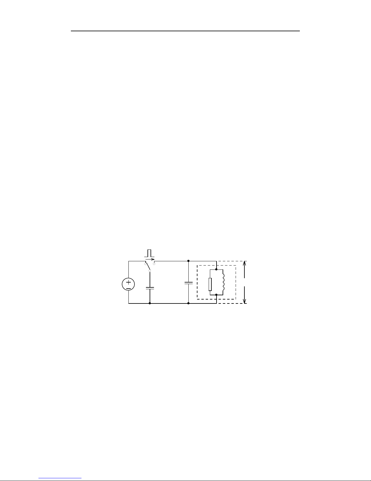
Principles of impulse winding test
The impulse winding tester tests the electrical characteristics of coil winding without damaging the
DUT. The prerequisite condition is to test the quality of a coil at just a glance. The detection is
carried out when the same electric impulse, as used in the standard coil and here discharged by a
capacitor, is applied to the DUT. The voltage attenuation wave is generated in response to the
impulse, related to the Q-factor and inductance of the coil. In this sense, the tester can detect turn
and layer short, the differences in the number of turns and the material of the core. If high impulse
voltage is applied, the poor insulation will appear as a corona or layer discharge.
Figure 1-1 Simplified diagram for principles of impulse winding test
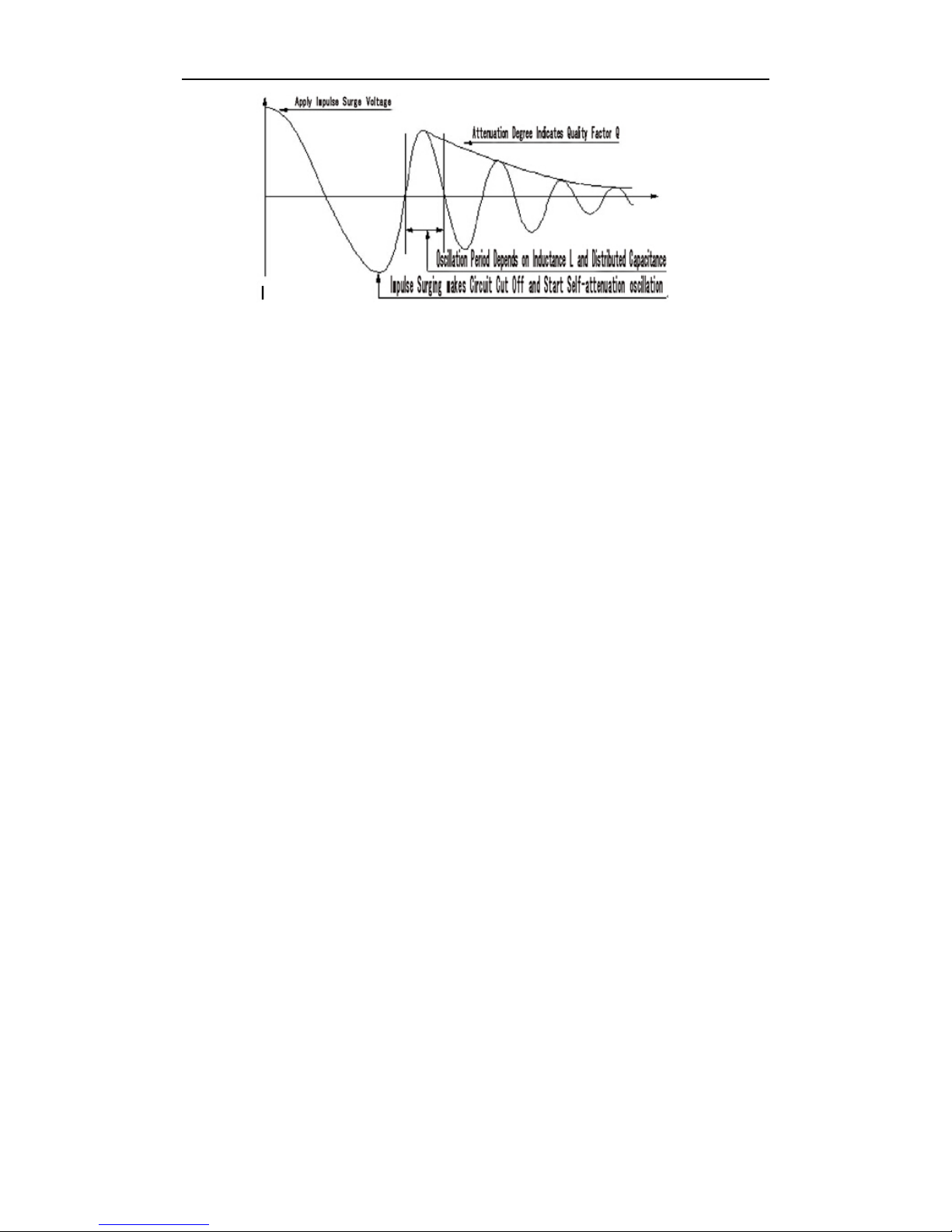
In figure 1-2, the self-oscillation attenuation wave has a close relation with the inductance L and
quality factor Q, while L and Q depend on the number of turn, manufacture technology,
properties of iron core material and whether it has air-coils. What’s more, the applied voltage is a
high impulse voltage, thus, it is easy to observe the short circuit, partial short turns and lays or
turns discharge phenomenon caused by insulation damage.
TH2883 Series Operation Manual Version:1.0.1
1-3
Figure 1-2 Typical self-attenuation oscillation wave
1.2 Operation environment
1.2.1 Power supply
Voltage: 198V-242V AC, 99V-121V AC
Power frequency: 47.5Hz-63Hz
Consumption: ≤40VA
1.2.2 Environment temperature and humidity
Normal working temperature: 0 ~40℃℃, Humidity: ≤ 90%RH
Referential working temperature: 20 ±8℃℃, Humidity: ≤ 80%RH
Transferring environment temperature: 0 ~50℃℃m, Humidity: ≤ 93%RH
1.2.3 Warm-up
The warm-up time should not be less than 15 minutes.
1.3 Dimensions and weight
Dimensions (W*H*D): 400mm×132mm×390mm
Weight: Approx. 7.2kg
TH2883 Series Operation Manual Chapter 2 General specifications
2-1
Chapter 2 General specifications
2.1 Specifications
Specifications TH2883-5 TH2883-10
Output for impulse voltage 100V~5000V
10V steps
5%±15V
500V~10000V
200V steps
5%±25V
Inductance test range >10μH >20μH
Impulse energy Max 250milli-Joules Max 500 milli-Joules
Contents in waveform
display area on LCD
800×480 dot-matrix LCD
250×600 dot-matrix
Setup parameters, standard wave and test wave, comparison result, file
information, etc.
Sample wave Sampling rate: 200MSPS/5ns, 100MSPS/10ns, 50MSPS/20ns,
25MSPS/40ns, 12.5MSPS/80ns, 6.25MSPS/160ns, 3.12MSPS/320ns,
1.56MSPS/640ns
Resolution: 8bits
Sampling point: 6000bytes
Standard wave sample Sequential cycle, single cycle, one sample (up to 32 times of sample
averaging)
Input impedance 5MΩ
Test speed 6 times/sec
Averaging rate
Number of test impulse 1 to 32 averaging rate
programmable
Number of demagnetizing impulse 0 to 16 averaging rate
programmable
Measurement function Voltage, time and frequency
Trigger mode Internal, Manual (Foot), External and Bus
Comparison method AreaSize Comparison
DiffZone Comparison
Corona Comparison
PhaseDiff Comparison
Area size measurement
accuracy
±1%
Area difference
measurement accuracy
±1%
TH2883 Series Operation Manual Chapter 2 General specifications
2-2
Comparison output PASS/FAIL display
Beeper alarm
Beep mode ON (adjust for high and low tone), OFF
Memory Built-in memory: 100 files
USB disk memory
Interface HANDLER (START, STOP, PASS, NG, BUSY, EOC, etc.)
RS232C USB Device USB Host LAN
2.2 Comparison methods
2.2.1 Area size comparison
As shown in figure 2-1, when comparison method is set to AREA SIZE, the area sizes of both
standard waveform and the tested waveform are calculated (integration method) between A and
B. The percent deviation is the ratio of the area size difference to the area size of the standard
waveform between A and B, expressed as a percentage.
Figure 2-1 Area Size Comparison
The area size of the waveform is nearly proportional to the energy loss in the winding. When a
sample winding has a short circuit between layers, the short circuit area is reflected as an
increase of energy loss.
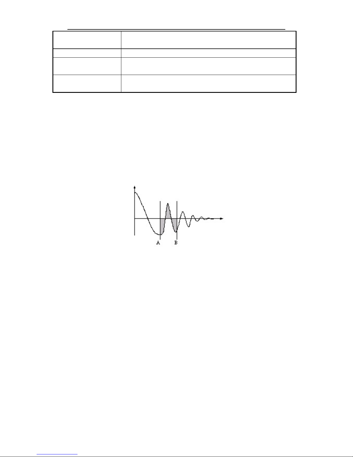
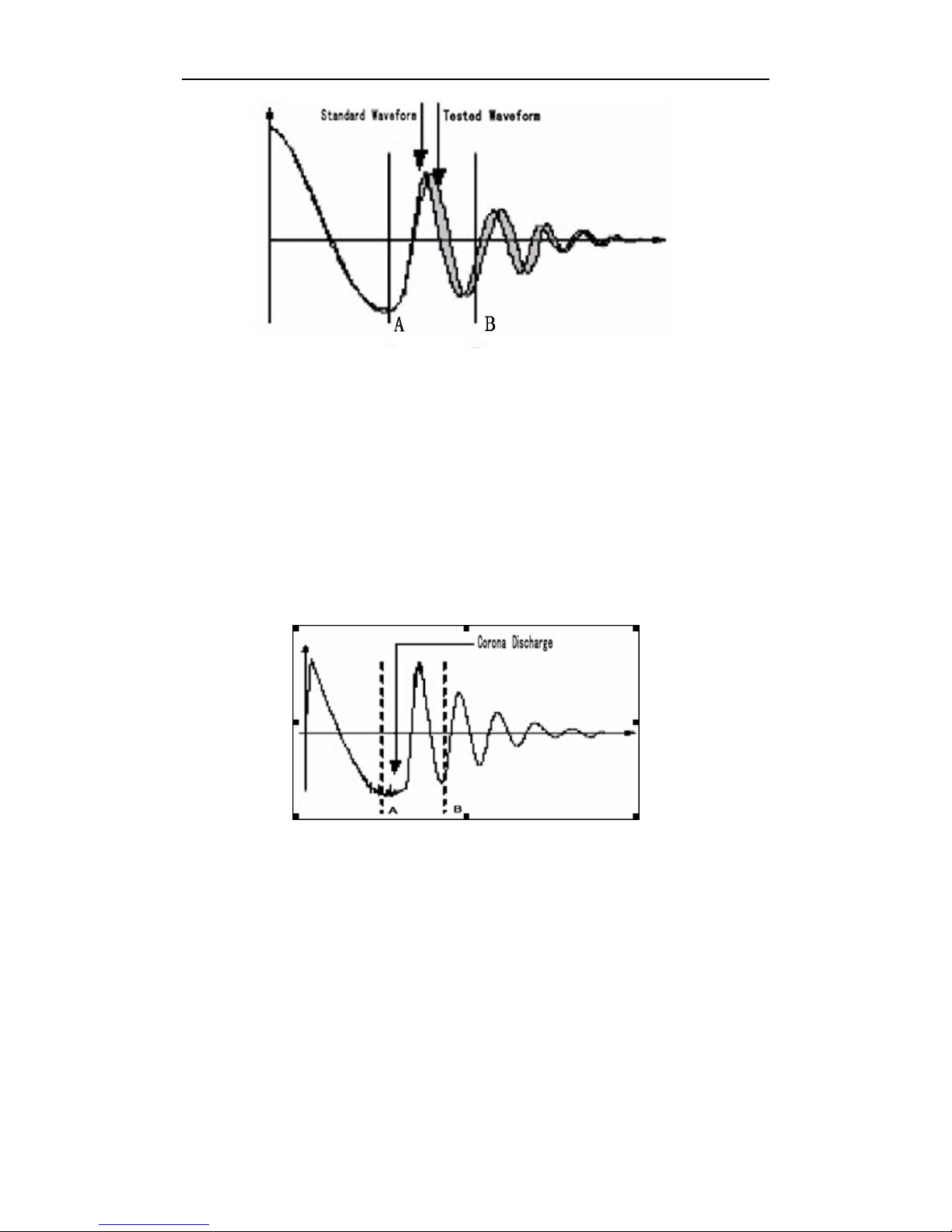
2.2.2 Differential area comparison
When comparison method is set to Differential Area, TH2883 calculates the area size of
differential portion between the standard waveform and the tested waveform from A to B. (The
differential portion area size is indicated as the shaded part in Figure 2-2.) The percent deviation
is the ratio of the differential portion area size to the area size of the standard waveform between
A and B, expressed as a percentage.
TH2883 Series Operation Manual Chapter 2 General specifications
2-3
Figure 2-2 Differential Area Comparison
The differential area size reflects the value of inductance and total energy loss. This method is
especially effective to detect the differences of inductance L between the standard winding and
the tested winding.
2.2.3 Corona discharge comparison
When comparison method is set to Corona Discharge, TH2883 detects the high frequency energy
of corona discharge from A to B as shown in Figure 2-3. When the corona evaluation value is
less than the corona difference limit, then the comparison result will be PASS. When the corona
evaluation value is more than the corona difference limit, then the comparison result will be
FAIL. The corona evaluation value and difference limit are both expressed as an integer.
Figure 2-3 Corona Discharge Comparison
User can sample some coil samples (e.g. 10 samples) to set an effective corona discharge value.
First, applying an impulse voltage to each coil will gain the corona discharge value of each coil.
Then, a new effective value can be set by adding 20% to the maximum corona discharge value.
In order to ensure the correctness of the new value, user can test these coils once more and
observe the corona PASS or FAIL.
TH2883 Series Operation Manual Chapter 2 General specifications
2-4
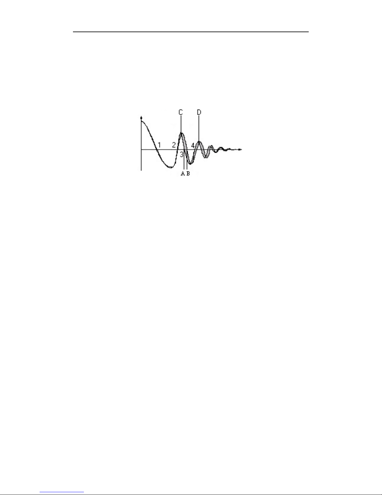
2.2.4 Differential phase comparison
User can specify a zero-crossing point to compare. The instrument will judge the zero-crossing
offset between the tested waveform and standard waveform and then compare the oscillation
period between the two waveforms. The percentage of the two values will be taken as the
judging criterion and the reference is set by percentage. As is shown in figure 2-4, A~B is the
offset and C~D is the oscillation period of standard waveform. The third zero-crossing point of
the compared waveform is to set.
Figure 2-4 Phase Differential Comparison
NOTE:
The tester can only set zero-crossing points from 2 to 10. The first zero-crossing point
cannot reflect the actual performance of coils, so it is not necessary to set the first point. In real
phase differential comparison, there are four results generated: PASS, FAIL, FAIL1 and FAIL2.
PASS is up to standard; FAIL, below standard. While FAIL1 means the zero-crossing point has
not been found, that is to say, it is unable to find the set zero-crossing point on the waveform of
the tested coil; FAIL2 indicates that a complete period cannot be found on the standard
waveform. As shown in figure2-4, the third zero-crossing point must be present in the waveform
so as to ensure the normal operation of phase differential comparison.
TH2883 Series Operation Manual Chapter 3 Panels and display
3-1
Chapter 3 Panels and display
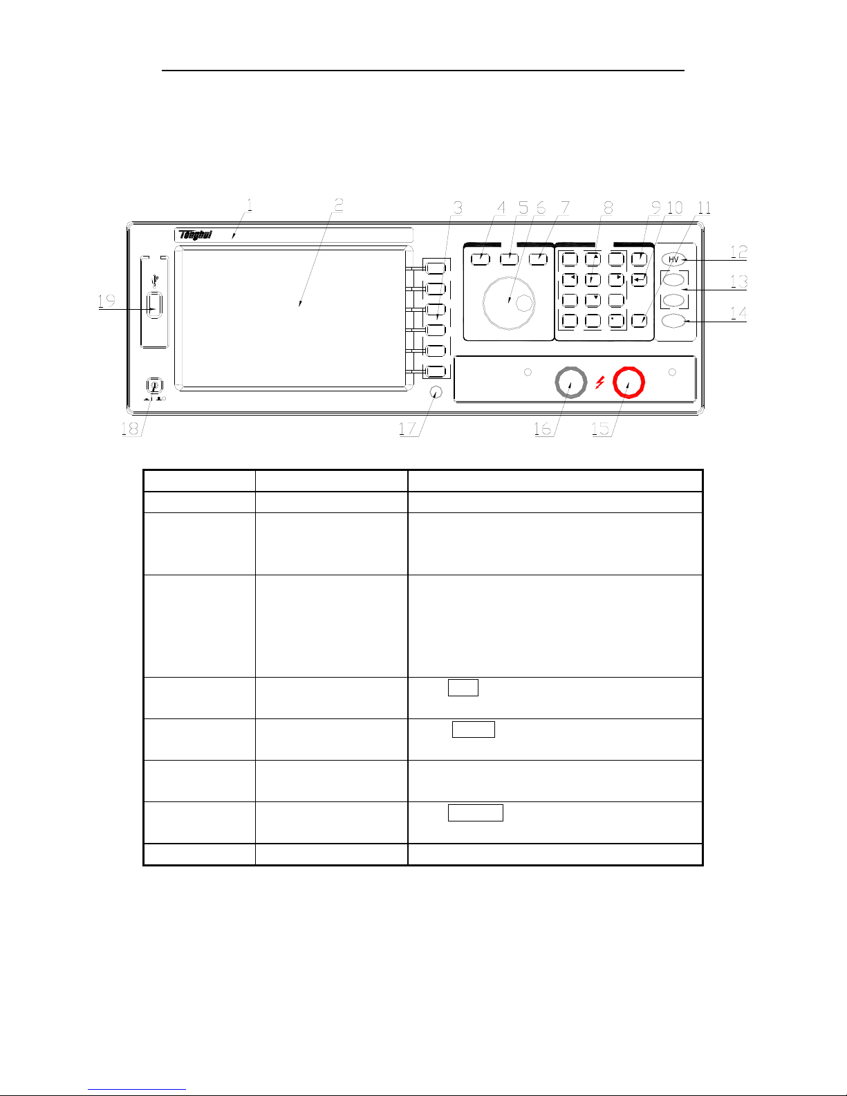
3.1 Front panel
USB
TH2883-5
Impulse Winding Tester
POWER
MENU
COPY
ENTRY
ESC
ENTER
DISP
SETUP
SYSTEM
PQRS
TUV WXYZ
789
+/-
PASS
FAIL
START
GHI JKL MNO
ABC DEF
654
123
0
Serial Number Name Instruction
1 Brand and model
2 LCD 320×240 Large-Scale dot-matrix LCD displays
measurement waveform, set parameters, system
configurations, etc.
3 SOFTKEY The five keys’ functions are not fixed and have
different functions in different menus. Five soft
keys are used to select control and parameter
functions. Current function of each soft key is
displayed along its left side.
4 [DISP] Press DISP menu key to enter the <MEAS DISP>
page.
5 [SETUP] Press SETUP menu key to enter the <MEAS
SETUP> page.
6 Roller Control the movement of the cursor, confirm and
modify data
7 [SYSTEM] Press SYSTEM menu key to enter the <SYSTEM
SETUP> page.
8 NUMBER keys Input numbers or characters
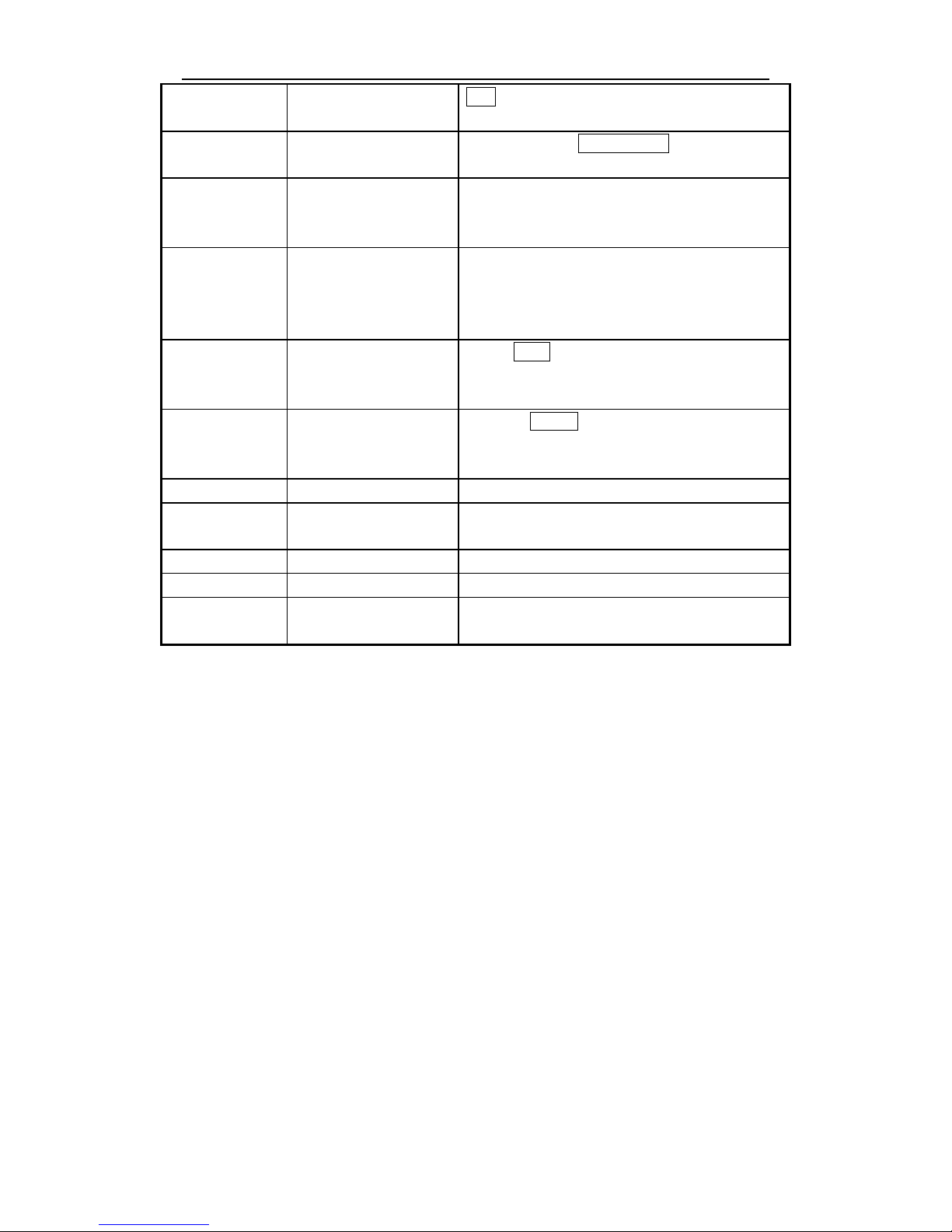
TH2883 Series Operation Manual Chapter 3 Panels and display
3-2
9 ESC ESC key is used to cancel the enter of numbers or
characters.
10 BACKSPACE The function of BACKSPACE key is to delete
numbers or characters wrongly entered.
11 ENTER ENTER key terminates numeric input data and
enters the displayed value on the data input line
(bottom line of the LCD screen).
12 HV High Voltage Indicator indicates that the
instrument is outputting dangerous impulse test
voltage to the HV terminal on the rear panel. Do
not touch test terminals or DUT.
13 PASS/FAIL indicator When PASS indicator flashes, the comparison
result is up to standard; while FAIL, below
indicator. Valid only in comparison function.
14 START Press the START key to start a measurement. In
the process of test, pressing the key will terminate
the measurement.
15 High voltage terminal Output high voltage.
16 Ground terminal Low terminal for high voltage test, connecting to a
test fixture and DUT with 15.
17 COPY Capture the screen information
18 POWER Switch on or off the main power
19 USB Host interface An USB disk can be connected for standard
waveforms and measurement conditions storage.
Table 3-1 Front panel instruction
TH2883 Series Operation Manual Chapter 3 Panels and display
3-3
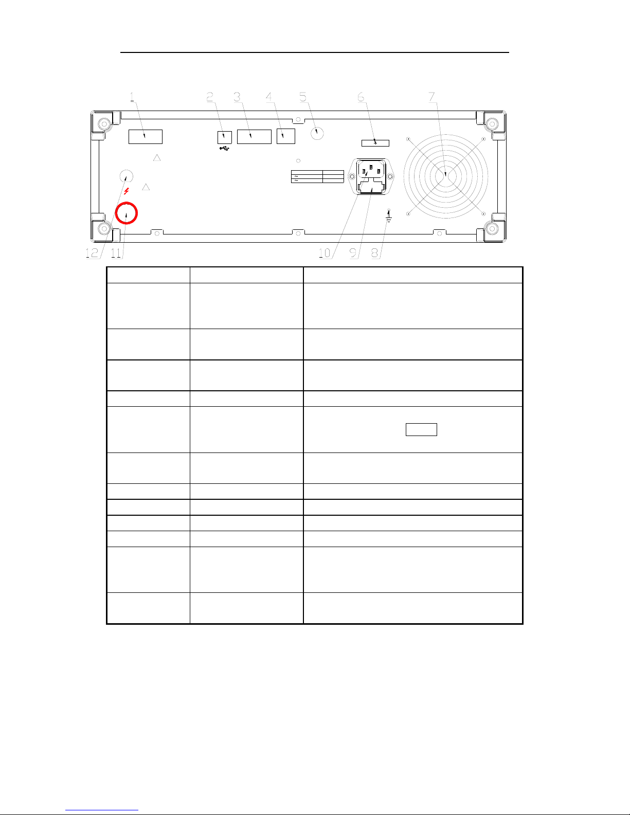
3.2 Rear panel
GND
FOOT.C
HANDLER
DEVICE
RS-232C
LAN
RATING
FUSE
T1AL
~
T2AL
110V
/ 60Hz
~
220V / 50Hz
HV
WARNING
THIS INSTRUMENT CONTAINS NO OPERATOR SERVICEABLE PARTS INSIDE;
REFER SERVICING TO SERVICE TRAINED PERSONNEL ONLY.
!
PLEASE READ MANUAL FOR SAFETY
DISCONNECT INPUT POWER BEFORE REPLACING FUSE FOR CONTINUED FIRE
PROTECTION,USE MANUAL SPECIFIED TYPE RATING FUSE ONLY.
!
Serial number Name Instruction
1 HANDLER interface Comparison results are output via the handler
interface. You can also start or stop a test through
the interface.
2 USB DEVICE interface A PC can remotely control TH2883 through the
USB DEVICE interface.
3 RS232C serial interface RS232C serial interface can be connected to an
external device for remote control and operation
4 LAN interface Be used to connect network cable.
5 FOOT CONTROL A footswitch can be used to start a measurement
instead of pressing the START key from the front
panel.
6 Name plate Show manufacture date, model, batch number,
manufacturer, etc.
7 Fan window Discharge heat.
8 Ground terminal Ground the instrument shell.
9 Fuse Fuse is used to protect the instrument .220V/1A
10 3-wire power socket Connect the power.
11 Test terminal High voltage output terminal, the function is the
same as that of the high voltage terminal on the
front panel.
12 Test terminal It is the GND terminal connected to the DUT with
11 and 16 on the front panel.
Table 3-2 Rear Panel Instruction
TH2883 Series Operation Manual Chapter 3 Panels and display
3-4
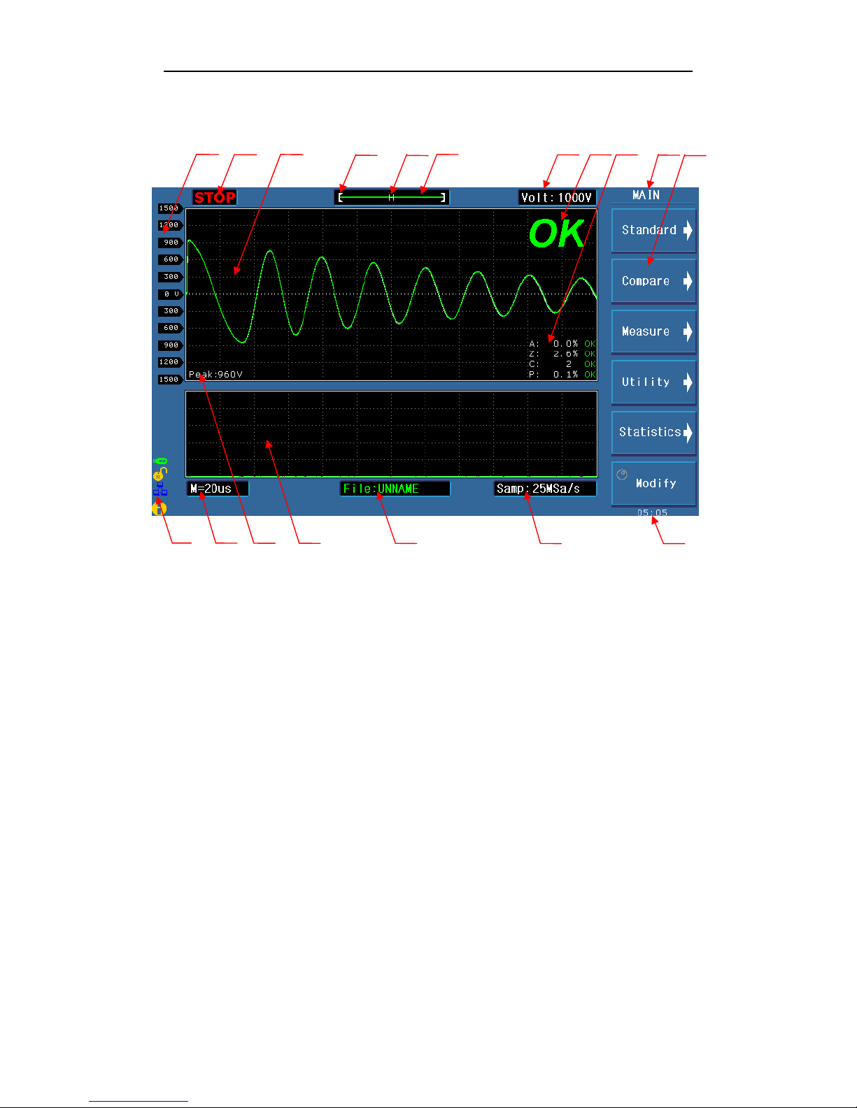
3.3 Introduction to display area
1 2 3 4 5 6 7 8 9 10 11
12 13 14 15 16 17 18
Specific definition for each area:
1 Voltage
Show the voltage of waveform
2 Test status
RUN means in the test process, STOP means the test has been terminated.
3 Waveform display area
In this area, test and standard waveforms, peaks of impulse voltage and comparison results
are displayed.
4 Indicate the waveform location in the memory.
5 Indicate whether a standard waveform exists. N means a standard waveform exists while H
does not.
6 Show the memory depth and indicate the current display color of the test waveform. User
can use the roller to change the color.
7 Impulse voltage
Show the current set impulse voltage. This voltage can be changed by the [Modify] soft key
and the roller.

TH2883 Series Operation Manual Chapter 3 Panels and display
3-5
8 Measurement result
Show the final measurement result.
9 Comparison result
Four comparison results and their final display results
10 Main menu for soft key
11 Function zones of soft keys
Show the corresponding function and parameter of each soft key.
12 Information
Show the state of interface selecting, availability of U disk, key lock, etc.
13 Time base
This area shows the time between the two dash lines of this waveform display area in X
direction. The time shown in this area cannot be modified by user but varies with the
sampling rate and time base zoom.
14 Peak value
Show the peak value of the current test voltage.
15 Secondary display zone
Display comparison methods and their basic parameters, extraction quantity of corona
16 File name
Show the name of the current file, *means no file.
17 Sampling rate
Show the sampling rate of the current waveform, which can be altered by the [Modify] soft
key and the roller.
18 Time
Display the real time.
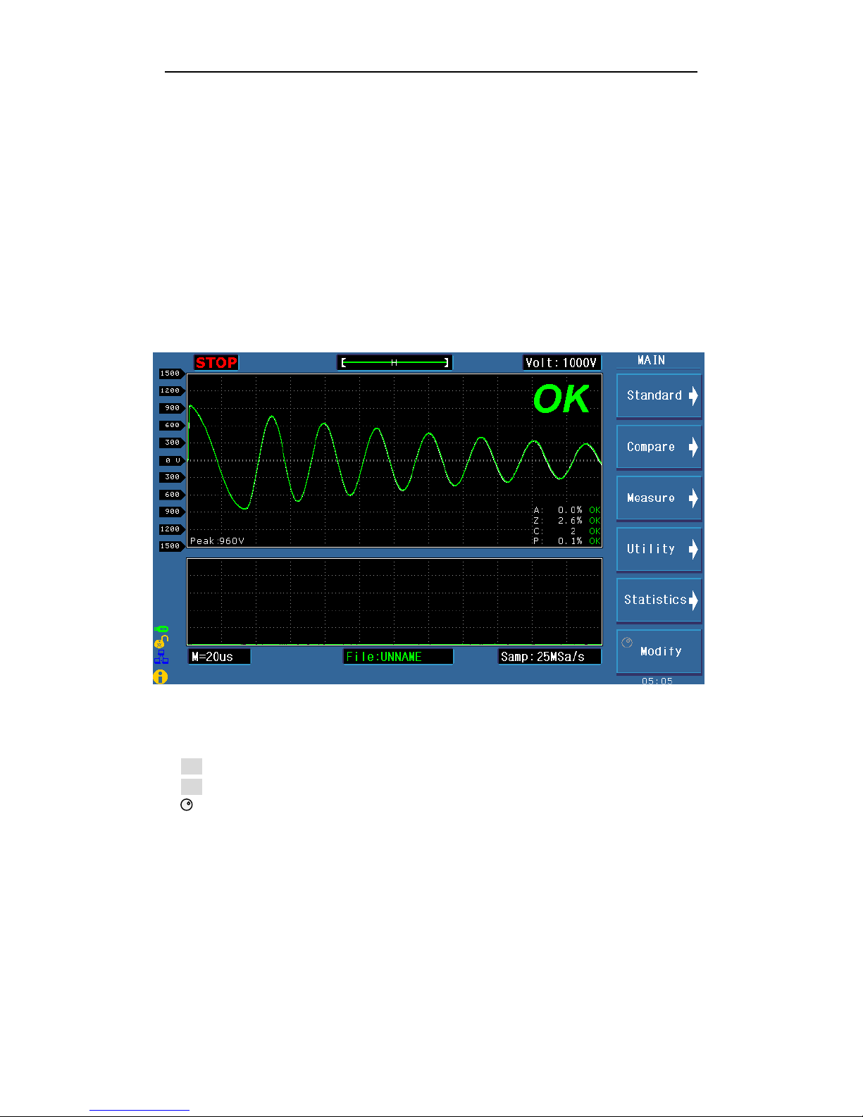
TH2883 Series Operation Manual Chapter 4 Introduction to [DISP]
4-1
Chapter 4 Introduction to [DISP]
Press the DISP menu key to enter the < MEAS DISP> page (the default page). In this page,
measurements are taken and the test waveform is displayed. Some function settings such as
standard sampling (Standard), comparison setting (Compare), measurement function (Measure),
auxiliary function (Utility), statistic function (Statistics), display color of the waveform,
sampling rate, etc. Figure 4-1 shows the measurement display page.
4.1 Measurement display page
Figure 4-1 Measurement display page
4.2 Introduction to symbols in measurement display page
Enter the next menu.
Return to the upper menu.
Lighten this symbol to enable the roller, while darken this symbol to disable the roller.
The roller can be rotated and has the function of key.

TH2883 Series Operation Manual Chapter 4 Introduction to [DISP]
4-2
4.3 Introduction to soft keys in measurement display page
Standard Enter the Standard sampling sub-menu. Under this menu, standard sampling
method, standard sampling, etc. can be selected.
Compare Enter the Compare setup submenu. Under this menu, states of the four compare
methods, compare parameters can be set.
Measure Enter the Compare function submenu. Under this menu, wave voltage, wave time,
wave frequency can be set.
Utility Enter the Utility function submenu. Under this menu, internal file, wave amplitude,
grid in the waveform display zone, corona display zone, and the state of the key lock can be
set.
Statistics Enter the Statistics function submenu. Under this menu, statistics for the current
test result can be set. User can select to open, clear or save data.
Modify Press the corresponding soft key and revolve the roller to modify the impulse
voltage, sampling rate, etc.
4.3.1 Standard sampling
The instrument provides three sampling modes: manual, auto and loop.
4.3.1.1 Manual Start to sample a standard waveform. When finished, standard
waveform will be displayed in the waveform display zone.
Complete Press this key to complete the acquisition of standard waveforms.
Average 1 Indicate the sampling times for standard waveform.
Undo Cancel the current acquisition data for standard waveform. Each
press of this soft key will reduce the sampling average times by 1.
This key is available when Average is larger than 1.
Undo All Cancel all acquisition data for standard waveform. This key is
available when Average is larger than 1.
Start Start to collect data for standard sample wave. Averaging can be
taken after multiple sample data is collected for several times.
Return to previous page.
4.3.1.2 AUTO At each frequency, the instrument automatically samples a standard
wave on the sample. Finally, a wave at an appropriate frequency
will be selected.
Display sample waveforms at lower frequencies.
Display sample waveforms at higher frequencies.
Select Select the sample waveform at the current frequency as the
standard waveform.
Select & Check Compare the sample wave with the standard wave at the
current frequency, if the compare result is within the error

TH2883 Series Operation Manual Chapter 4 Introduction to [DISP]
4-3
range, choose the sample wave at the current frequency as the
standard wave and return to the main menu; if the compare
result is beyond the error range, an error information will
prompt and the instrument will keep in the wait state to Start a
new sample.
Start Start automatic test.
Return to previous page.
4.3.1.3 LOOP The instrument starts to sample standard waveforms, change frequency,
and cycle sampling.
Select Select the sample waveform at the current frequency as the standard
waveform.
Select & Check Compare the sample wave with the standard wave at the
current frequency, if the compare result is within the error
range, choose the sample wave at the current frequency as
the standard wave and return to the main menu; if the
compare result is beyond the error range, an error
information will prompt and the instrument will keep in the
wait state to Start a new sample.
Start Start loop test.
Return to previous page.
4.3.1.4 Modify Lighten the icon to enable the roller. Revolve the roller to choose or
modify the wave color, voltage and sample rate.
Revolve the roller to move the cursor to this zone and press the
roller for one time. Then rotate the roller to choose the wave color.
Revolve the roller to move the cursor to this zone. Then rotate the
roller to change the voltage by 10V. The voltage ranges from 100V
to 5000V.
Revolve the roller to move the cursor to this zone. Then rotate the
roller to select the desired sample rate.
4.3.1.5 Return to the main menu.
4.3.2 Compare
TH2883 series provides four kinds of compare methods as follows: Area Size Comparison,
Differential Area Comparison, Corona Discharge Comparison and Phase Differential
Comparison. The instrument collects the waveform data of 6000 points, thus user can select
the comparison area between the start position and 6000.
Press the Compare soft key to enter the main menu of it. Four compare methods can be set
under this menu.
【 N 】
Volt 1000
V
Samp: 200MSa/s

TH2883 Series Operation Manual Chapter 4 Introduction to [DISP]
4-4
Note: Press the soft key to enable the roller. When the roller is revolved,
two parallel yellow lines (except Differential Phase comparison) will be displayed in
the waveform display zone. The full line is the selected one, while the dash line is not
the selected one.
4.3.2.1 AREA SIZE
Select the area comparison method.
State means this method is turned on, while means off.
Lighten this icon to enable the roller. The start point, the end point
or both the start and the end points will be selected by the press of
the roller. Revolve the roller will change the position of the start
point, the end point or both the start and the end points by 10
points. The position ranges from 0 to 6000.
Lighten the icon to enable the roller and change the differential
value.
Return to previous page.
4.3.2.2 DIFF ZONE
Select the differential area size comparison method. All setup
operations are the same as those of AREA SIZE.
4.3.2.3 CORONA
Select the corona comparison method. All setup operations are the
same as those of AREA SIZE. The corona comparison value has no
unit ranging from 1 to 255.
4.3.2.4 PHASE DIFF
Select the phase differential comparison method. All setup
operations are the same as those of AREA SIZE. But the position
parameter is different, it means to choose the zero-crossing
position and the value ranges from 2 to 99.
4.3.2.5 Return to the main menu.
4.3.3 Measure
Measurement function is used to measure impulse voltage, time and frequency.
Note: When a function is selected and the roller is enabled, two lines will be displayed
Position
0000-6000
Method
AREA
Position
0000-6000
Diff
2.0%
Method
DIFF ZONE
Method
Corona
Method
Corona
Method
PHASE DIFF

TH2883 Series Operation Manual Chapter 4 Introduction to [DISP]
4-5
in the waveform display zone. The differential value of the two lines corresponds to the
value showing on the second soft key.
Press the roller to switch between the high limit, the low limit and the
high and low limits. Then revolve the roller to change the position of
the high and the low limits. The voltage differential value between the
high and the low limits (ΔV) is as shown on the second soft key.
Note: The default low limit locates on the center line.
The high limit, the low limit or the high and the low limits can be
selected by the press of the roller. Then revolve the roller to change
the position of the high and the low limits. The differential value
between the high and the low limits (Δs) is as shown on the second
soft key.
The high limit, the low limit or the high and the low limits can be
selected by the press of the roller. Then revolve the roller to change
the position of the high and the low limits. The differential value
between the high and the low limits (ΔHz) is as shown on the second
soft key.
Return to the main menu.
4.3.4 Utility
Utility function is used to set waveform files and parameters displayed in the waveform
display zone.
File Press this soft key, the internal file system page will pop up and the soft key
zone will display soft keys under File Menu. See 5.3 Operation for intern al
file system for details.
Scale Lighten the icon and enable the roller. Then revolve the roller to enlarge the
waveform display scale ranging from 1 to 3 times. When the display scale is
larger than 1 times, the ratio will be displayed in the top right corner of the
waveform display zone.
Grid means the grid is turned on, while is off.
2nd means the corona is turned on. The secondary display zone will display
the quantity of the extracted corona.
means the corona is turned off. The secondary display zone will display
basic test parameters of the standard waveform and the comparison
methods.
Key This soft key is used to lock the keyboard. When the function is enabled, the
icon will be displayed in the information zone. This soft key is also the
Unlock key.
Voltage
1000V
Time
10.00μs
Freq
100.00KHz

TH2883 Series Operation Manual Chapter 4 Introduction to [DISP]
4-6
Unlock This soft key is used to unlock the keyboard. Its icon is .
Return to the main menu.
4.3.5 Statistics
Check, save or clear statistic results.
Press Statistics, the statistics page will pop up. This page shows each method’s measure
times, pass times and ratio of pass.
Stat e means this function is turned on, while is off.
Clear Clear the current statistic results.
Save Save the current statistic data to external U disk. The default format is csv.
Return to the main menu.
4.3.6 Modify
See 4.3.1.4.
TH2883 Series Operation Manual Chapter 5 Introduction to [SETUP]
5-1
Chapter 5 Introduction to [SETUP]
Press SETUP to enter the <Setup> page. This is a toggle key, by pressing it, the displayed page
can be toggled among <Setup>, <Int. File>, <Ext. File>.
5.1 Introduction to icons of soft keys
Numerical arrow key. Lighten this icon to enable this key. Respectively press the
four keys, 8, 2, 4, 6, the cursor will move up, down, left and right. When the icon
becomes dark, the numerical arrow key is disabled. Likewise the cursor can be moved
by pressing START (except in the measure display page).
NOTE: When the icon is lightened, the original numerical input function for the four
numerical keys will be invalid.
Coarse adjustment key used to increase the selected value.
Coarse adjustment key used to decrease the selected value.
Fine adjustment key used to increase the selected value.
Fine adjustment key used to decrease the selected value.
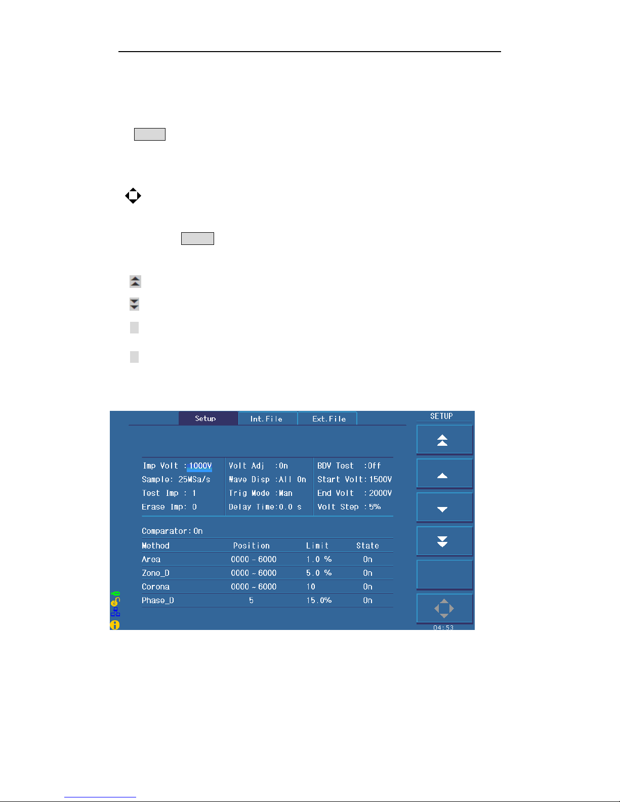
5.2 Measurement setup page
Figure 5-1 shows the measure setup page.
Figure 5-1 Measure setup page

TH2883 Series Operation Manual Chapter 5 Introduction to [SETUP]
5-2
Follow parameters can be set in <Setup>.
Impulse voltage (Imp Volt)
Sampling rate (Samp)
Test impulse (Test Imp)
Erase impulse (Erase Imp)
Voltage adjustment (V olt ADJ)
Wave display (Wave Disp)
Trigger mode (Trig Mode)
Delay time (Delay Time)
Breakdown voltage test (BDV)
Start voltage(Start Volt)
End voltage (End Volt)
Voltage step(Volt Step)
Comparator (Comparator)
Position (Position)
Limit (Limit)
State (State)
5.2.1 Imp Volt
The impulse voltage can be adjusted from 100V to 5000V by a resolution of 10V. Move the
cursor to the impulse voltage zone, following soft keys will be displayed.
They are coarse adjustment keys used to increase and decrease the voltage by a
resolution of 100V.
They are fine adjustment keys used to increase and decrease the voltage by a
resolution of 10V.
Lighten this key to enable the numerical arrow key. Respectively press 8, 2, 4, 6, the
cursor will move up, down, left and right.
Note: User can directly input the desired voltage by numerical keys. In the state of
inputting numbers, soft keys are unavailable. When the number is input, ENTER can be
used to end inputting and the default unit is volt (V).
5.2.2 Samp
200MSa/s, 100MSa/s, 50MSa/s, 25MSa/s, 12.5MSa/s, 6.25MSa/s, 3.12MSa/s, 1.56MSa/s are
optional for sample rate. Move the cursor to the sample rate zone, following soft keys are
available.
Be used to select the desired sample rate.
Lighten this key to enable the numerical arrow key. Respectively press 8, 2, 4, 6, the
cursor will move up, down, left and right.
 Loading...