

Tonghui TH2822, TH2822C, TH2822A Instruction Manual
Model
Dual Handheld LCR Meter
TH2822/TH2822A/TH2822C
Instruction Manual

1
Safety Summary
The following safety precautions are
applicable to both operating and
maintenance personnel and must be
observed during all phases of operation,
service, and repair of this instrument.
DO NOT OPERATE IN A FLAMMABLE OR
EXPLOSIVE ATMOSPHERE
Do not operate the instrument in the
presence of much dust, direct sunlight, high
humidity, strong electromagnetic radiation,
etc.
NON-PROFESSIONALS SHUOLD NOT OPEN
THE REAR COVER
Maintaining, substituting parts or adjusting
the instrument should be made by
professional maintenance personnel. Please
contact relevant distributor or Tonghui’s
after-sale service department.

2
DO NOT RE MOVE OR MODIFY THE
INSTRUMENT
Some replacements and unauthorized
modifications might cause irreversible
damage to the instrument.
SAFETY WARNING
Strictly follow the relevant safety statements in
this manual involving safety, personnel injury,
damage to the instrument, operation and
environmental conditions causing poor test.

3
Safety Guidelines
To ensure that you use this device safely,
follow the safety guidelines listed below:
This meter is for indoor use, altitude up to
2,000 m. For short-time outdoor use,
precautions should be taken to avoid direct
sunlight, water and moisture,
electromagnetic radiation, dust and
explosion.
The warnings and safety precautions should
be read and well understood before the
instrument is used.
Use the meter only as specified in this
manual.
Confirm that the circuits have been powered
off and all capacitors in the circuits been
discharged before measuring in-circuit
components.
Discharge all charging elements, such as
capacitors, before testing.
The power for the meter is supplied with a
single standard 9V battery. But also a line
operation is possible using a power adapter
4
of 12VDC/150mA. If a power adapter is
selected, please be sure to meet the safety
requirements of a relevant IEC standard.
The battery using in TH2822C is
rechargeable. Do not charge nonrechargeable batteries.
Safety Symbols
This symbol is a warning and
indicates that the user should refer to
the operating instructions located in
the manual.
D C power
Indicates inside pin is positive (+),
outside is negative (-) .

5
Environme ntal Con diti ons
Operating Enviro nment
0 °C to 40 °C
Storage Humidity
0 – 80% R.H.
Storage Enviro nment
-20 °C to +50 °C
Pollution degree
2

6
Contents
Safety Sum ma ry ........................................................ 1
Safety Guideli n es ...................................................... 3
Introduction ............................................................... 9
Package Contents ................................................... 10
Front Panel Overvie w ............................................. 12
Front Panel Display Descriptions .................................. 13
Front Panel Buttons ...................................................... 15
Button Function Definition ............................................. 16
LCD Display Overview .................................................. 17
LCD Display Descriptions ............................................. 17
Special Display Indicators ............................................. 19
Test Port ....................................................................... 19
Powering Instrument .............................................. 21
Installing Battery ........................................................... 21
Connecting External Power Source .............................. 24
Low Battery Indication .................................................. 26
Backlight Display .......................................................... 27
Charge Display ............................................................. 28

7
Operation Instruction.............................................. 30
Data hold mode (HOLD) ............................................... 30
Data Record Mode (REC) ............................................. 31
L/C/R/Z Select Mode .................................................... 33
D/Q/θ/ESR Select Mode ............................................... 34
Test Frequency (FREQ)................................................ 34
Tolerance Mode (TOL) ................................................. 35
Auto LCR Mode ............................................................ 37
Measurement Rate (RATE) .......................................... 39
Series/parallel Equivalent Mode ................................... 39
Utility Menu (UTIL) ........................................................ 41
Clear Functions (CLEAR) ............................................. 52
Remote Control (RMT) ................................................. 56
Fuse Detection .............................................................. 56
Quick Start Guide .................................................... 58
CAUTION...................................................................... 58
Inductance Measurement ............................................. 59
Capacitance Measurement ........................................... 62
Resistance Measurement ............................................. 64
Impedance Measurement ............................................. 66
Remote Communicati o n ......................................... 67

8
Connecting Instrument to PC ........................................ 67
Virtual Serial Port Configuration .................................... 68
RMT Operation ............................................................. 69
Command Protocols ..................................................... 71
Command Reference .................................................... 77
Specifications .......................................................... 84
General Specifications .................................................. 84
Accuracy Specifications ................................................ 87
Maintenance ............................................................ 94
Service .......................................................................... 94
Cleaning........................................................................ 95
Limited Warranty ..................................................... 96

9
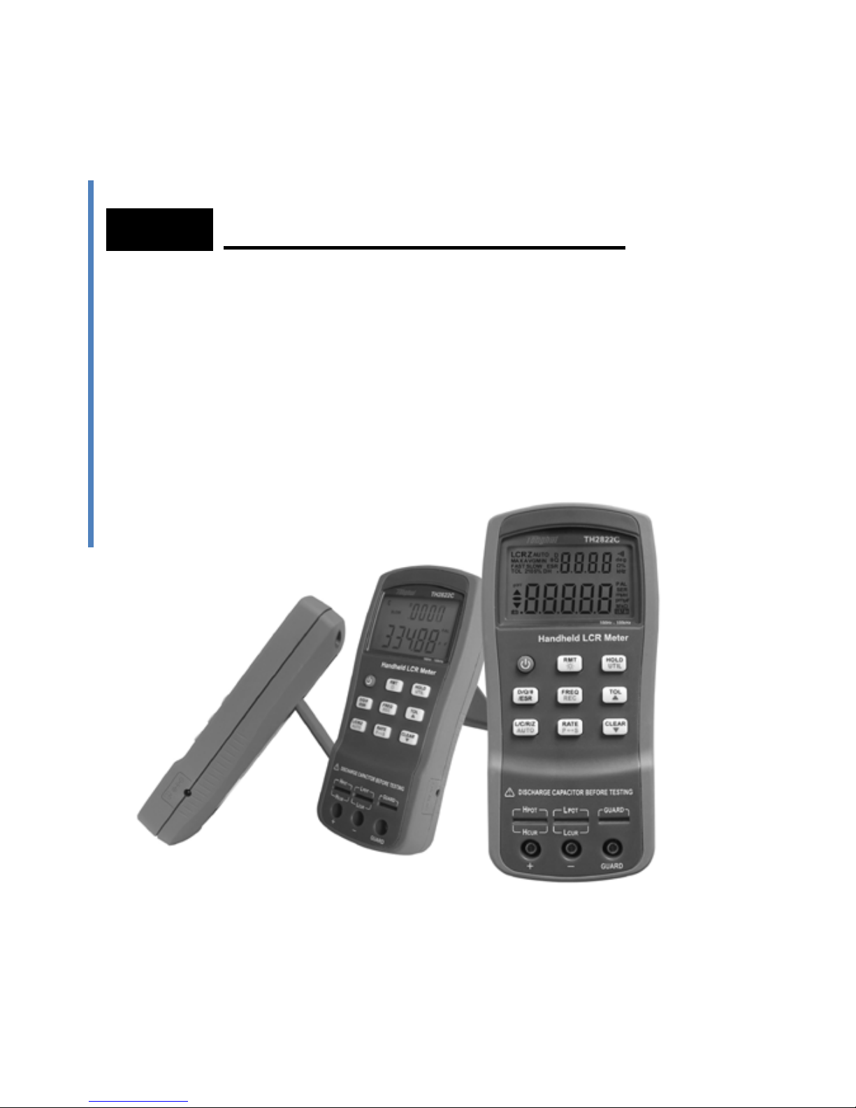
Introduction
TH2822 series are des i gn e d f or m eas uring ind uct ance ,
capacitance and resistance components. The
instrument can be powered by a 9V battery or external
power adapter. The meter is not only applicable to the
application occasion of bench meters but also
conveniently used in the flow inspect and handheld
measurement occasions.
TH2822 series provide the primary parameter of up to
40,000 readings, secondary parameter of 0.0001
reading resolution, the maximum measuring
frequency of up to 100kHz, constant internal
resistance of 100Ω and testing level of 0.6Vrms. The
auto range can rapidly display the measuring results
and automatically choose the desirable testing
parameter s in ac c ordanc e with c omponents pr oper t ies .
Its measuring accuracy is up to 0.25%.
Front panel push buttons maximize the convenience
of function and feature selection such frequency, rate
and L/C/R/Z selection. Tolerance mode can sort
components, record mode aid to capture readings,
convenient open/short clear function improve the
measuring accuracy, utility menu help you easily take

10
the selections of the key tone, auto power-off and
storage.
All TH2822 series are equipped with the function of
remote communication. The test data can be
transferred to PC through a Mini USB connection,
great for applications that require remote control and
data acquisition.
Package Contents
TH2822 series are equipped with the following
contents:
• TH2822/TH2822A/TH2822C handheld LCR
meter
• Instruction manual
• Mini USB Interface Cable
• Red / Black Banana plugs—Crocodile clip
Test Leads
• Short-circuit plate
• *9V Alkaline battery or 8.4 rechargeable
battery
• *AC adapter
• *TH26027A Kelv in clip tes t lea ds
• * TH26009C SMD test tweezers

11
• *TH26029C SMD test tweezers
* This can be purchased as optional accessories. All
contents are subject to actual package list or box.
Please locate them from the original packaging to
ensure nothing is missing. If in the case that an item is
missing, please contact Tonghui or relevant distributor
immediately.
12
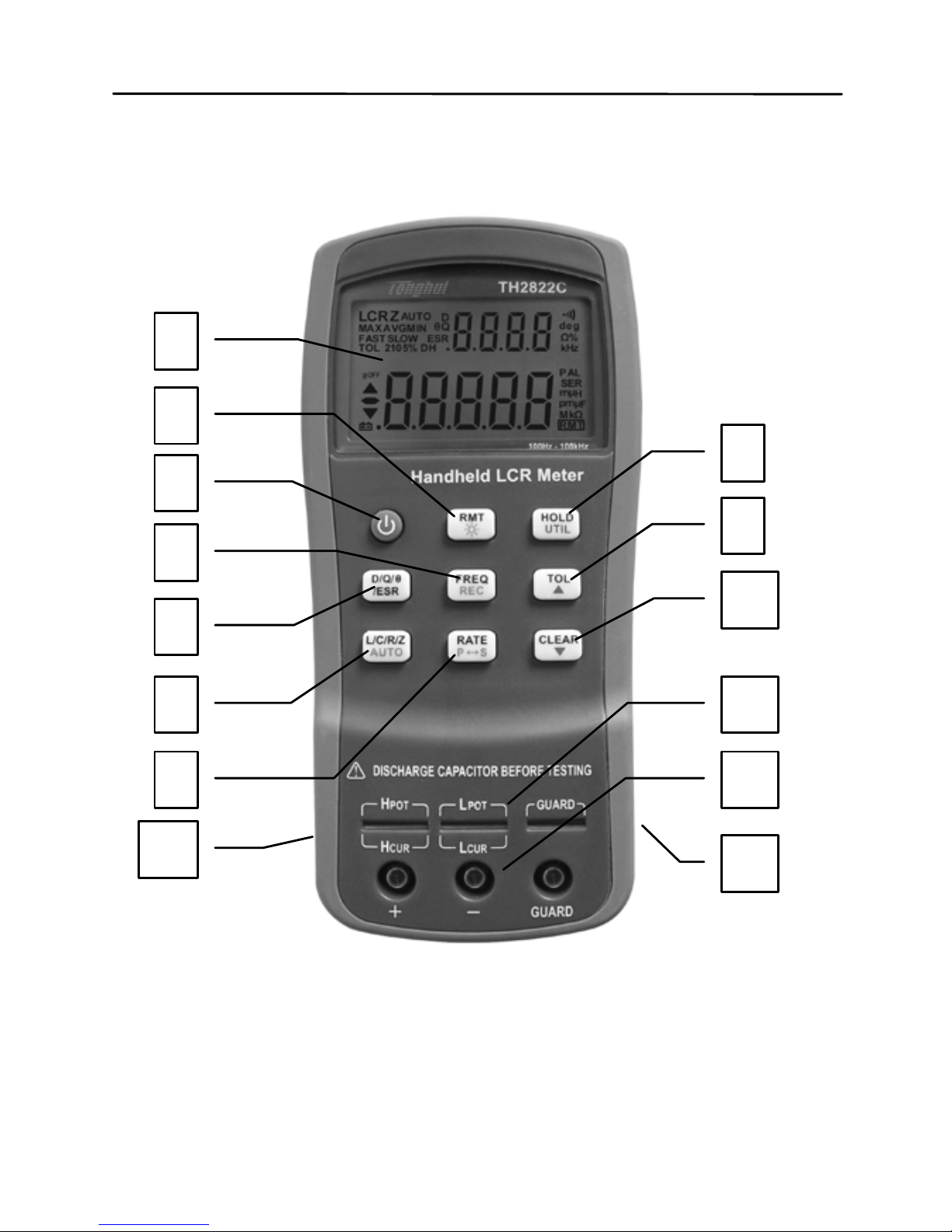
Front Panel Overview
Figure 1 - Front Panel Display (model TH2822C shown)
1 2 3
5
6
8 4 7
13
9
10
11
12
14

13
Front Panel Display Descriptions
1. LCD display
2. USB communication / *Back light button
3. Power ON/OFF button
4. Frequency and record mode selection
5. Secondary display mode (D /Q//ESR, etc.)
6. Primary display mode (L/C/R/Z, etc.)/ auto
LCR selection
7. Rate/equivalent mode selection
8. Hold mode/ utility menu
9. Tolerance mode/ utility arrow key
10. Open/short clear/ utility arrow key
11. 5-terminal test sockets (direct measurement
on lead components or use of test fixture)
12. 3-terminal test jacks (for use of Banana plugs
—Crocodile clip Test Leads)
13. Standard mini USB port (for remote control)
14. 12VDC external power input (use with an
external power adapter)
*Backlight is not included in TH2822.
NOTE: Refer to the adapter
’
s label for input
parameters of it. Rated output parameters is 12VDC
,
150mA,4mm.
NOTE: Use with included power adapter only or
purchase the specified adapters from Tonghui. Use

14
with improper power adapters may damage
instrument.
NOTE: Internal battery supply will be
automatically cut off since the normal supply of
external power. If the battery is rechargeable
(TH2822C), the external power will charge the battery
simultaneously. TH2822C is installed an independent
charging controller---charging control is still done even
at the state of power-off.
WARNING: Before connecting an external
power adapter, b e sure that the polarity ma tches
the (+) and (-) labels as indicated inside the battery
compartment. If it is not installed correctly and
connected to an external power adapter, it might
cause severe damage to the instrument.
WARNING: If the battery is rechargeable
(TH2822C), please be sure that the polarity
matches the (+) and (-) labels as indicated inside
the battery compartment ant the battery is
rechargeable. DO NOT charge the nonrechargeable battery!

15
Front Panel Buttons
With the exception of the power button, all front panel
buttons have specific colored labels on them. They
are all marked in black, blue, or orange color. Each
color has a specific representation, as described
below:
Black—the primary function,meaning that
function will be set or configured upon pressing it.
Orange—the secondary function, it means that
the function will be set or configured if that button is
pressed and hold down for 2 seconds.
Blue—the utility function, the function will be set
or configured if the UTIL button is pressed and hold
down for a long time. See “Utility Menu” section for
details.
NOTE: In the button operational instruction, we
will use the button name to express the button
operation without differentiating the type of button;
Pay attention to the difference between “long press”
and “press”.

16
HOLD
FREQ
L/C/R/Z
/ESR
UTIL
CLEAR
RMT
P
S
TOL
RATE
AUTO
REC
D/Q/
θ
1 2 3 4
8
9 5
7 6
Figure 2 –Button Display (Model TH2822C shown)
Button Function Defi n ition
1. Power ON/OFF Button
2. Frequency/Record Mode Button
3. Remote Control/Bac klight Button
4. Readings Hold/Utility Menu Button
5. Tolerance mode/ Menu Selection Button
6. Clear/ Menu Selection Button
7. Rate/Equivalent Mode Button
8. LCR Primary Parameters/Auto LCR
9. Secondary Parameters Selection Button

17
LCD Display Overview
LCR
ESR
MAXAVGMIN
θ
Q
AUTO
D
2105%
deg
kHz
PAL
SER
μ
H
p
F
μ
RMT
Mk
TOL
DH
n
n
@
OFF
Z
%
Ω
FASTSLOW
1
2 5 9 10
12
14
16
202127
28
29
8
3
23
24
25
4
15
11
13
6 7
22
17
18
19
Ω
26
Figure 3 - LCD Indicator Display
LCD Display Descriptions
1. LCRZ – Primary display indicator
2. MAX – Maximum reading indicator in the
record mode
3. AVG – Average reading indicator in the record
mode
4. MIN – Minimum reading indicator in the record
mode
5. AUTO – Automatic LCR indicator
6. θ – Phase angle indicator for secondary
display
18
7. D – Dissipation indicator
8. Q – Quality factor indicator
9.
– Secondar y display
10.
– Beeper tone indicator for tolerance
mode
11. deg – Phase angle (θ) units indicator
12. Ω – ESR(ohm) units indicator
13. % - Percentage indicator (in tolerance mode)
14. kHz – Frequency units indicator
15. PAL – Parallel mode indicator
16. SER – Series mode indicator
17.
– Inductance units (L) indicator
18.
–Capacitance units (C) indicator
19. MkΩ – Resistance(R) /impedance units
indicator
20. RMT – Remote mode indicator
21.
– Primary display
22. ESR – Series mode indicator for secondary
parameters
23. DH – Data hold indicator
24. SLOW – measuring rate indicator
25. 2105% - Limits indicator in tolerance mode
26. FAST- Fast measuring rate indicator
27.
– Low battery/charging indicator
28. @OFF –Auto power-off indicator
19
29. TOL –Tolerance mode indicator
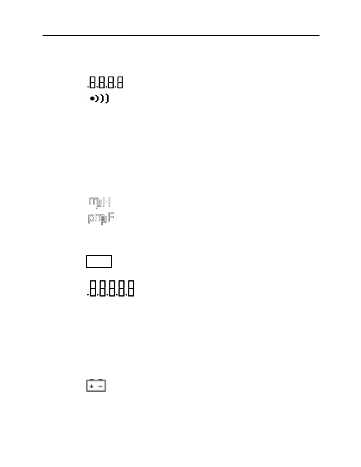
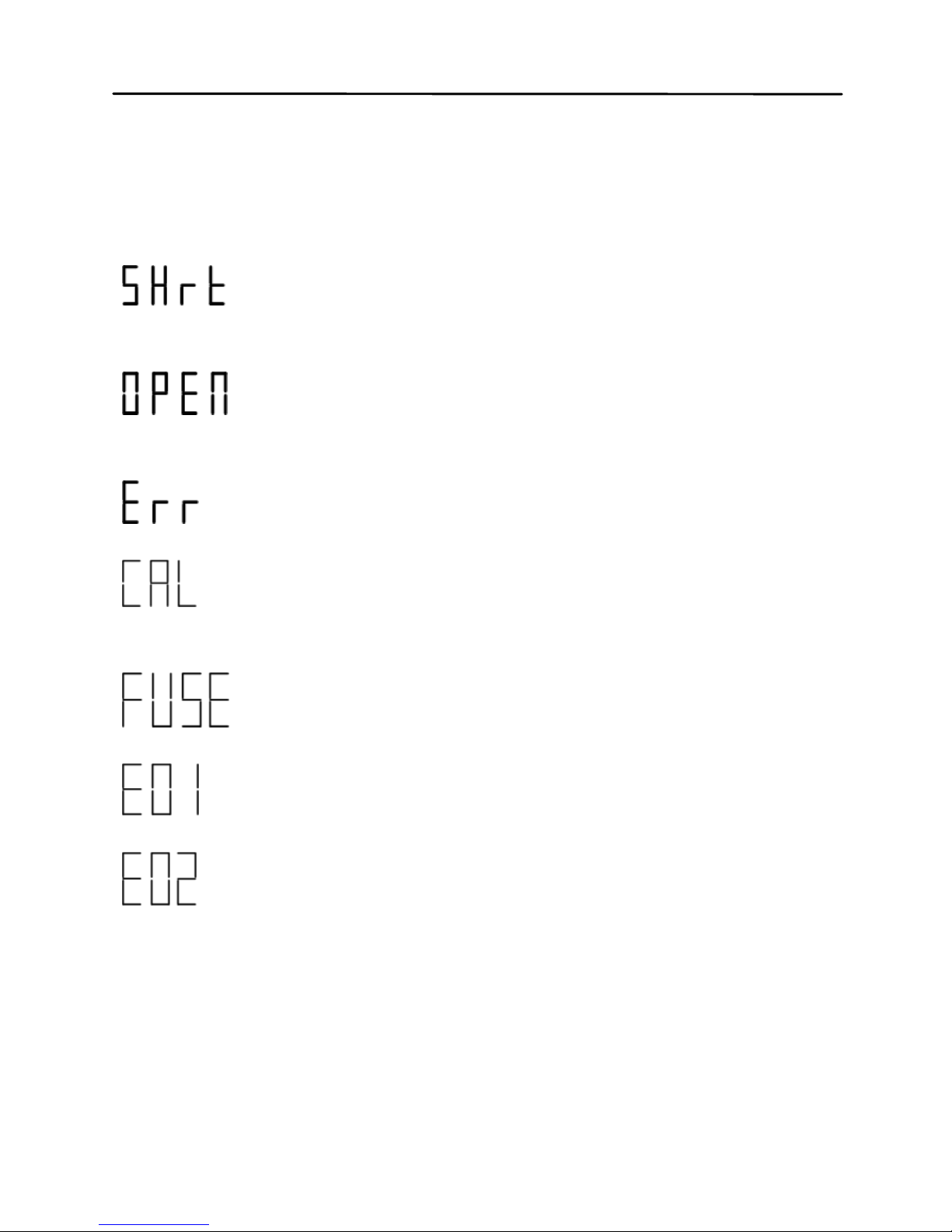
Special Display Indicators
Indicates short clear if you press the
CLEAR button
Indicates open clear if you press the
CLEAR button
Error indication
Indicates correction (open/short clear)
mode
Indicates damaged or open fuse
AD converter error(UNK)
AD converter error(END)
Test Port
TH2822 series are creatively designed to combine 3terminal port and 5-terminal port, which makes the
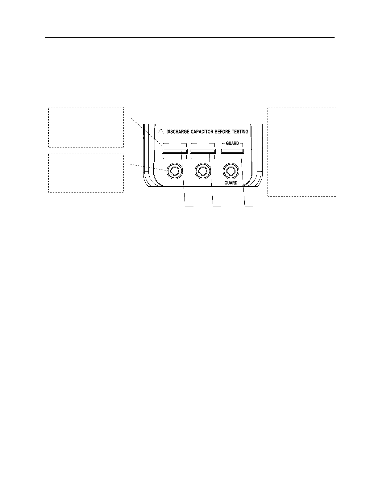
20
convenient test and highly accurate test realized in the
instrument.
+ -
!
H
CUR
L
CUR
H
POT
L
POT
1 2 3
Figure 4- test port
With the adoption of standard banana slots, the
instrument can use inexpensive banana plugcrocodile clip as the test lead, which make the test
quite convenient. However this configuration has low
testing accuracy.
For the improvement of accuracy when using external
testing leads, TH2822 series are designed with 5terminal testing slots and exclusive test fixture to
ensure complete external 4-terminal test and
measuring accuracy.
5-terminal
test slot
3-terminal
test port
1-Hight
Terminal
2-Low
Terminal
3-Guard
Terminal

21
NOTE: TH26027A, TH26009C, TH 260 29C 4-terminal
test fixtures are optional for TH2822 series. Please
refer to relevant instrument accessories.
Powering Instrument
There are two methods to supply the instrument:
Battery and external power adapter. When the two
power modes are available, the external DC adapter
is prior to the battery. The two power modes can be
automatical l y switche d with out inter ru pti on.
Installing Battery
TH2822 series can adopt battery for power supply so
that you can take measurements whenever and
wherever without many preparations.
9V alkaline batteries used in TH2822/TH2822A are
non-rechargeable. Reference standard type is
IEC6LR61.

22
TH2822C applies 8.4V rechargeable battery with
LH-200H7C as the reference type. Do not use nonrechargeab le batteries with the exception o f
emergency cases. The reason is that the charging
circuit will operate once the instrument is
connected to external power.
To Install the Battery:
1. Open up the back-flip stand, and locate the
screw that tightens the battery compartment
cover as indicated in Figure 5. Use a
screwdriver to unscrew and remove the cover.
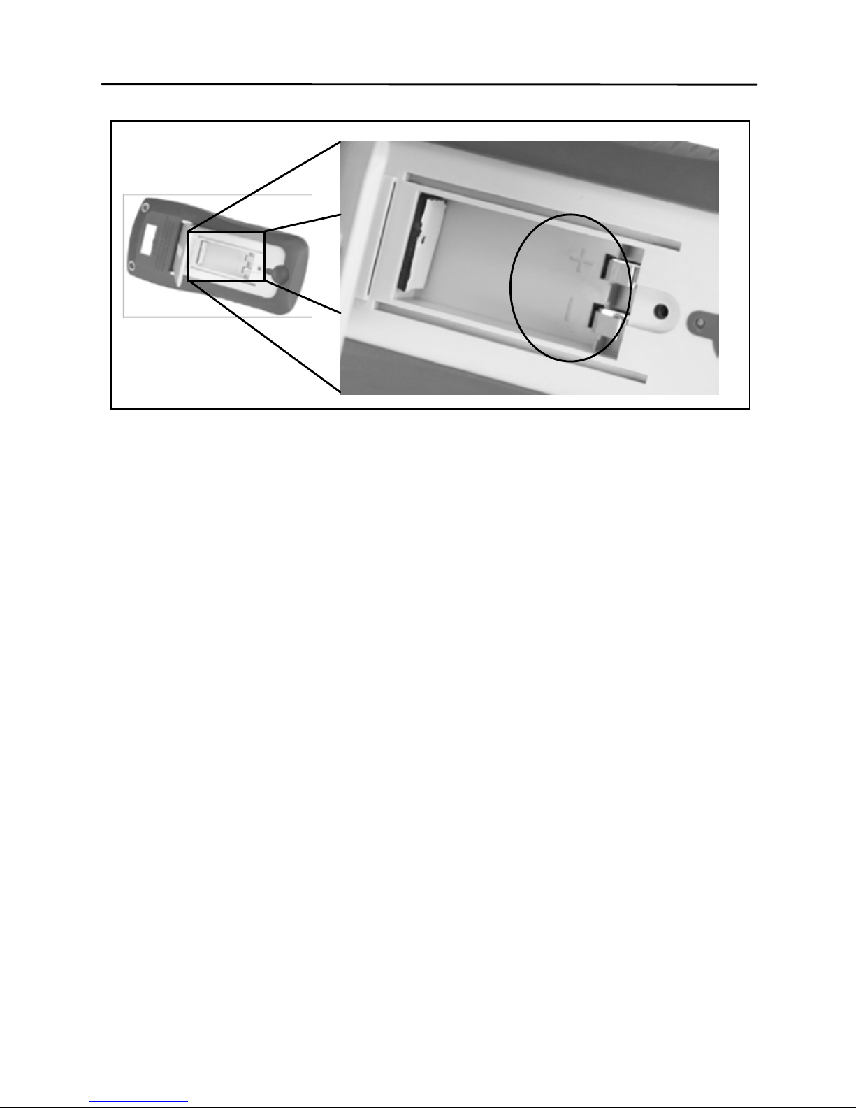
2. Insert proper battery into compartment. Note
the positive (+) and negative (-) terminals as
indicated inside the battery compartment
(See Figure 6). Be sure to insert the battery
with matching polarity.
3. Place the battery compartment cover piece
by sliding it into the top slid first. Place screw
at the bottom of the cover piece and tighten
down with a screw driver.
4. Push and hold down the power ON/OFF
button for 2 seconds to turn on the instrument.

23
Figure 5- Back Cover
24
Connecting External Power Source
Some models of TH2822 series are equipped with
standard external power adapters, which can use
external source.
WARNING: Use the included or specified adapter
only. Confirm p o wer p arameters be ones that
adapters require before use.
Figure 6- Battery Compartment

25
To connect the adapter, do the following:
1. If a battery is installed, please check the
battery compartment again that the polarity of
the battery matches the polarity as indicated
by the labels inside the compartment.
WARNING: DO NOT, at any tim e, connect an
external power adapter when a battery is installed
incorrectly or a non-rechargeable battery is
inserted in a rechargeable instrument. Doing so
will damage the in strument and void its warranty.
2. Confirm that an appropriate power supply
connects to the adapter.
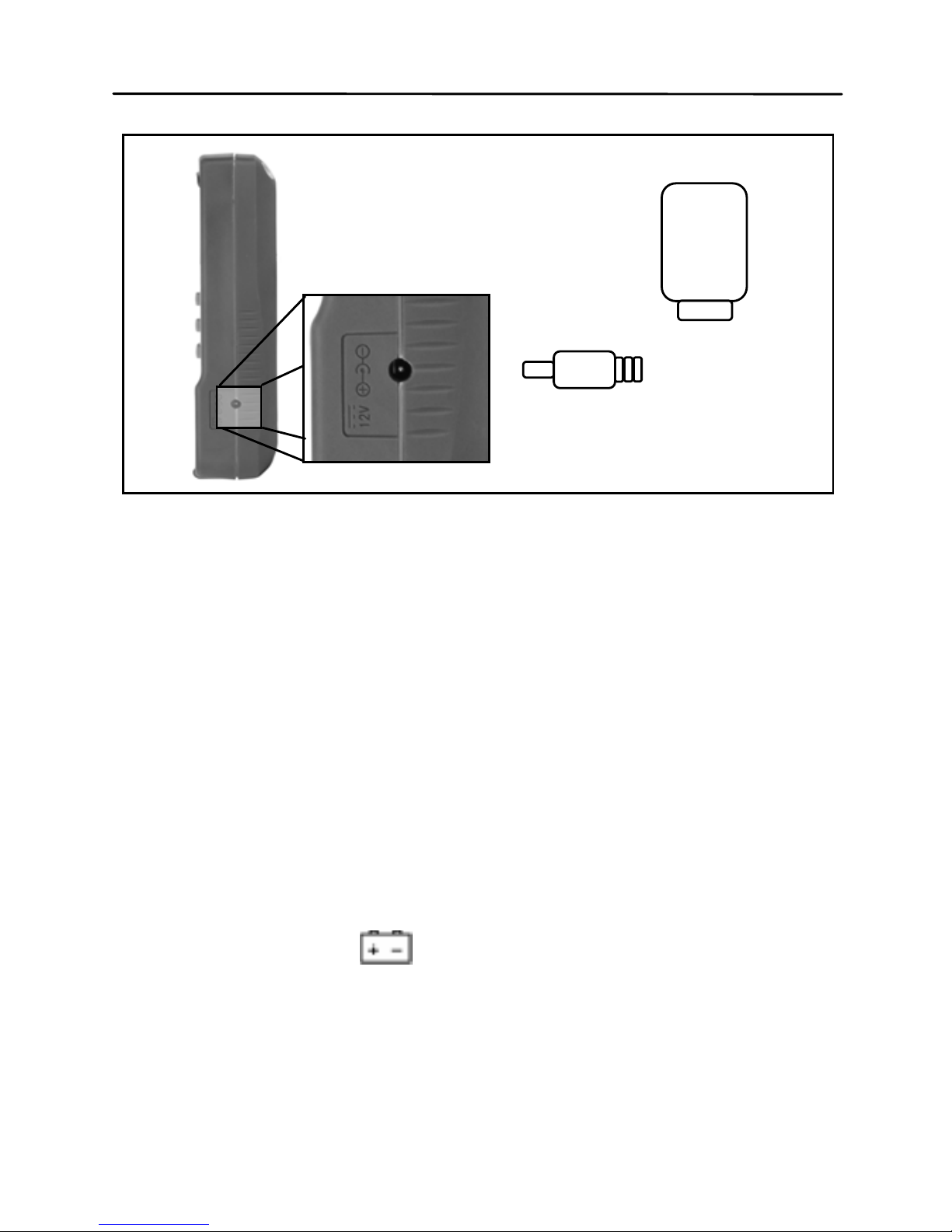
3. Connect the AC adapter connector into the
right side jack of 12VDC.
4. Connect the AC Adapter socket into an
electrical outlet.
5. Press and hold down the power button for
about 2s to turn on the meter.
26
NOTE: The meter will automatically switch to
consume power from the AC adapter instead of the
battery when an AC adapter is plugged in and
consume the power normally. In this event, if the
battery insta lled c orrect ly is rec hargeab le (for inst ance,
TH2822C), charging controller will be driven at the
same time no matter the instrument is on or off.
Low Battery Ind ication
At the use of battery for power supply, if the display
starts flashing the
indicator, it means that the
battery voltage is below normal working voltage
(below 6.8V). It is highly recommended that the
battery be replaced as soon as possible before
12VDC Input
AC Adapter
Figure 7-Connecting AC Adapter to Meter

27
continuing operation. See “Instal lin g Batt er y” for
instructions.
If the battery is rechargeable, when the
indicator
starts flashing, please charge the battery before
continuing operation. When the external source is
plugged in, the flash of
indicator indicates the
charging state.
Backlight Display
Only TH2822A/C meters have Backlight display that
can allow you to see the LCD display in dark
conditions, TH2822 doesn’t support backlight.
To turn on the back light, you should press the
button for a long time.
To turn off the back light, you should press the
button for a long time.
When Using Battery Power
When the meter is powered by using battery, the
brightness of the back light will automatically decrease
to conserve battery power. When the back light have
lightened for about 15 seconds, the brightness will
continuously decrease; and when the back light have

28
lightened for approximate 30 seconds, the back light
will automatic all y turn of f .
When Using Exter n al Power
When the meter is powered using an external AC
adapter, once the back light is turned on, it will stay at
its maximum brightness continuously and will not
automatical l y turn off . Unplugg ing the ex ter na l po wer
to use battery power, the back light will decrease its
brightness and automatically turn off.
Charge Display
The power circuit of TH2822/A is non-rechargeable.
When the external power adapter is plugged in, the
power mode will automatically switched and the
battery power circuit will be cut off.
TH2822C is equipped with rec har gea ble circuit. When
the external power adapter is connected, the built-in
rechargeable battery will be charged automaticall y
and the power mode will be switched to external
power supply.
Single charge circle is about 80 minutes and charge
current is approximate 40mA. If a battery is full
charged, the charge wi ll be automaticall y shut off ;

29
instead, the battery will be charged again after a
charge circle.
NOTE: A new charge circle will begin as soon as an
external power is connected.
WARNING: If the instrument has rechargeable
circuit, DO NOT connect to an external power
when a non-rechargeable battery is installed.
Doing so will cause the burst of the battery.
: It indicates low power of battery if not
connect to external power; if instrument is
connected to external power, it means the
charging state.
 Loading...