

Page 1
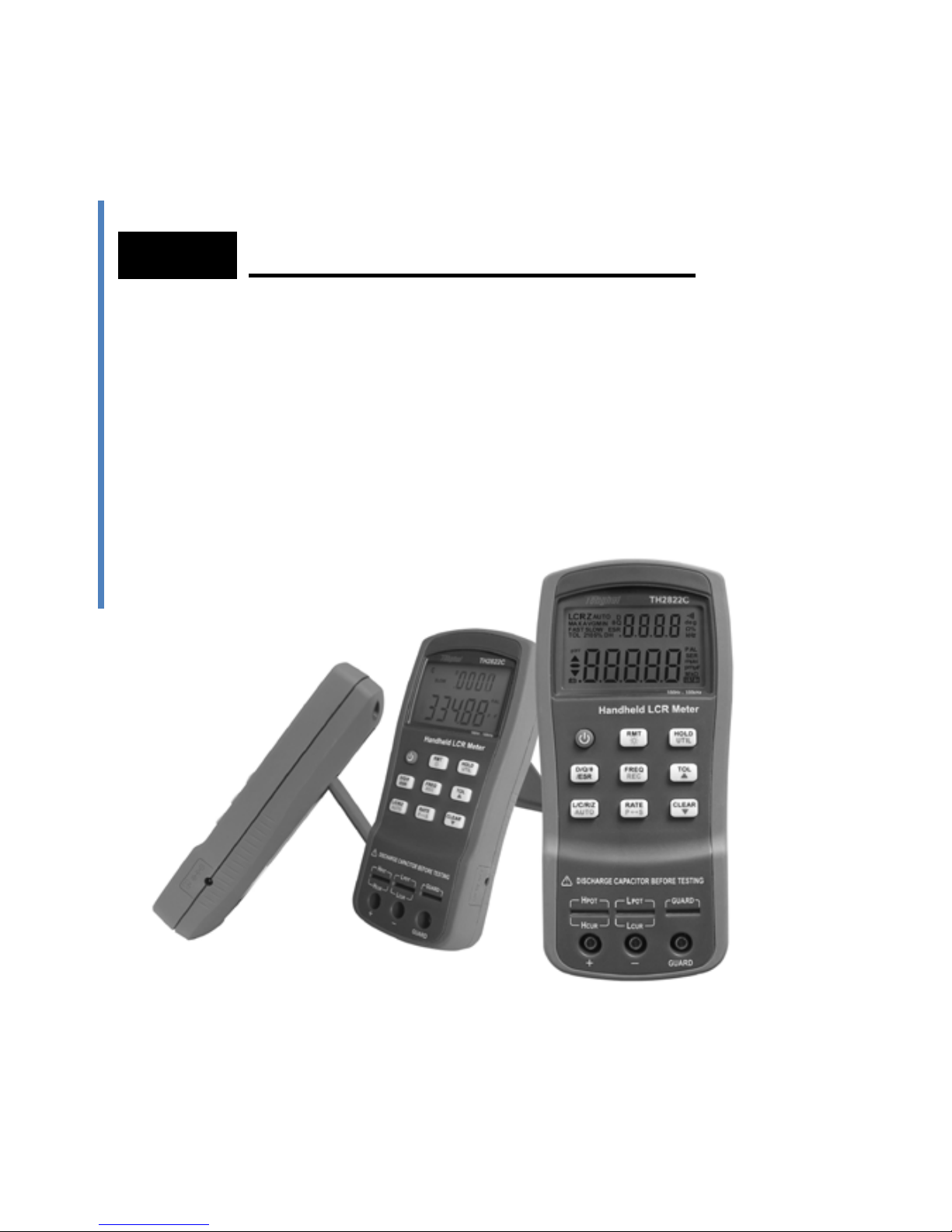
Model
Dual Handheld LCR Meter
TH2822/TH2822A/TH2822C
Instruction Manual
Page 2

1
Safety Summary
The following safety precautions are
applicable to both operating and
maintenance personnel and must be
observed during all phases of operation,
service, and repair of this instrument.
DO NOT OPERATE IN A FLAMMABLE OR
EXPLOSIVE ATMOSPHERE
Do not operate the instrument in the
presence of much dust, direct sunlight, high
humidity, strong electromagnetic radiation,
etc.
NON-PROFESSIONALS SHUOLD NOT OPEN
THE REAR COVER
Maintaining, substituting parts or adjusting
the instrument should be made by
professional maintenance personnel. Please
contact relevant distributor or Tonghui’s
after-sale service department.
Page 3

2
DO NOT RE MOVE OR MODIFY THE
INSTRUMENT
Some replacements and unauthorized
modifications might cause irreversible
damage to the instrument.
SAFETY WARNING
Strictly follow the relevant safety statements in
this manual involving safety, personnel injury,
damage to the instrument, operation and
environmental conditions causing poor test.
Page 4

3
Safety Guidelines
To ensure that you use this device safely,
follow the safety guidelines listed below:
This meter is for indoor use, altitude up to
2,000 m. For short-time outdoor use,
precautions should be taken to avoid direct
sunlight, water and moisture,
electromagnetic radiation, dust and
explosion.
The warnings and safety precautions should
be read and well understood before the
instrument is used.
Use the meter only as specified in this
manual.
Confirm that the circuits have been powered
off and all capacitors in the circuits been
discharged before measuring in-circuit
components.
Discharge all charging elements, such as
capacitors, before testing.
The power for the meter is supplied with a
single standard 9V battery. But also a line
operation is possible using a power adapter
Page 5
4
of 12VDC/150mA. If a power adapter is
selected, please be sure to meet the safety
requirements of a relevant IEC standard.
The battery using in TH2822C is
rechargeable. Do not charge nonrechargeable batteries.
Safety Symbols
This symbol is a warning and
indicates that the user should refer to
the operating instructions located in
the manual.
D C power
Indicates inside pin is positive (+),
outside is negative (-) .
Page 6

5
Environme ntal Con diti ons
Operating Enviro nment
0 °C to 40 °C
Storage Humidity
0 – 80% R.H.
Storage Enviro nment
-20 °C to +50 °C
Pollution degree
2
Page 7

6
Contents
Safety Sum ma ry ........................................................ 1
Safety Guideli n es ...................................................... 3
Introduction ............................................................... 9
Package Contents ................................................... 10
Front Panel Overvie w ............................................. 12
Front Panel Display Descriptions .................................. 13
Front Panel Buttons ...................................................... 15
Button Function Definition ............................................. 16
LCD Display Overview .................................................. 17
LCD Display Descriptions ............................................. 17
Special Display Indicators ............................................. 19
Test Port ....................................................................... 19
Powering Instrument .............................................. 21
Installing Battery ........................................................... 21
Connecting External Power Source .............................. 24
Low Battery Indication .................................................. 26
Backlight Display .......................................................... 27
Charge Display ............................................................. 28
Page 8

7
Operation Instruction.............................................. 30
Data hold mode (HOLD) ............................................... 30
Data Record Mode (REC) ............................................. 31
L/C/R/Z Select Mode .................................................... 33
D/Q/θ/ESR Select Mode ............................................... 34
Test Frequency (FREQ)................................................ 34
Tolerance Mode (TOL) ................................................. 35
Auto LCR Mode ............................................................ 37
Measurement Rate (RATE) .......................................... 39
Series/parallel Equivalent Mode ................................... 39
Utility Menu (UTIL) ........................................................ 41
Clear Functions (CLEAR) ............................................. 52
Remote Control (RMT) ................................................. 56
Fuse Detection .............................................................. 56
Quick Start Guide .................................................... 58
CAUTION...................................................................... 58
Inductance Measurement ............................................. 59
Capacitance Measurement ........................................... 62
Resistance Measurement ............................................. 64
Impedance Measurement ............................................. 66
Remote Communicati o n ......................................... 67
Page 9

8
Connecting Instrument to PC ........................................ 67
Virtual Serial Port Configuration .................................... 68
RMT Operation ............................................................. 69
Command Protocols ..................................................... 71
Command Reference .................................................... 77
Specifications .......................................................... 84
General Specifications .................................................. 84
Accuracy Specifications ................................................ 87
Maintenance ............................................................ 94
Service .......................................................................... 94
Cleaning........................................................................ 95
Limited Warranty ..................................................... 96
Page 10

9
Introduction
TH2822 series are des i gn e d f or m eas uring ind uct ance ,
capacitance and resistance components. The
instrument can be powered by a 9V battery or external
power adapter. The meter is not only applicable to the
application occasion of bench meters but also
conveniently used in the flow inspect and handheld
measurement occasions.
TH2822 series provide the primary parameter of up to
40,000 readings, secondary parameter of 0.0001
reading resolution, the maximum measuring
frequency of up to 100kHz, constant internal
resistance of 100Ω and testing level of 0.6Vrms. The
auto range can rapidly display the measuring results
and automatically choose the desirable testing
parameter s in ac c ordanc e with c omponents pr oper t ies .
Its measuring accuracy is up to 0.25%.
Front panel push buttons maximize the convenience
of function and feature selection such frequency, rate
and L/C/R/Z selection. Tolerance mode can sort
components, record mode aid to capture readings,
convenient open/short clear function improve the
measuring accuracy, utility menu help you easily take
Page 11

10
the selections of the key tone, auto power-off and
storage.
All TH2822 series are equipped with the function of
remote communication. The test data can be
transferred to PC through a Mini USB connection,
great for applications that require remote control and
data acquisition.
Package Contents
TH2822 series are equipped with the following
contents:
• TH2822/TH2822A/TH2822C handheld LCR
meter
• Instruction manual
• Mini USB Interface Cable
• Red / Black Banana plugs—Crocodile clip
Test Leads
• Short-circuit plate
• *9V Alkaline battery or 8.4 rechargeable
battery
• *AC adapter
• *TH26027A Kelv in clip tes t lea ds
• * TH26009C SMD test tweezers
Page 12

11
• *TH26029C SMD test tweezers
* This can be purchased as optional accessories. All
contents are subject to actual package list or box.
Please locate them from the original packaging to
ensure nothing is missing. If in the case that an item is
missing, please contact Tonghui or relevant distributor
immediately.
Page 13
12
Front Panel Overview
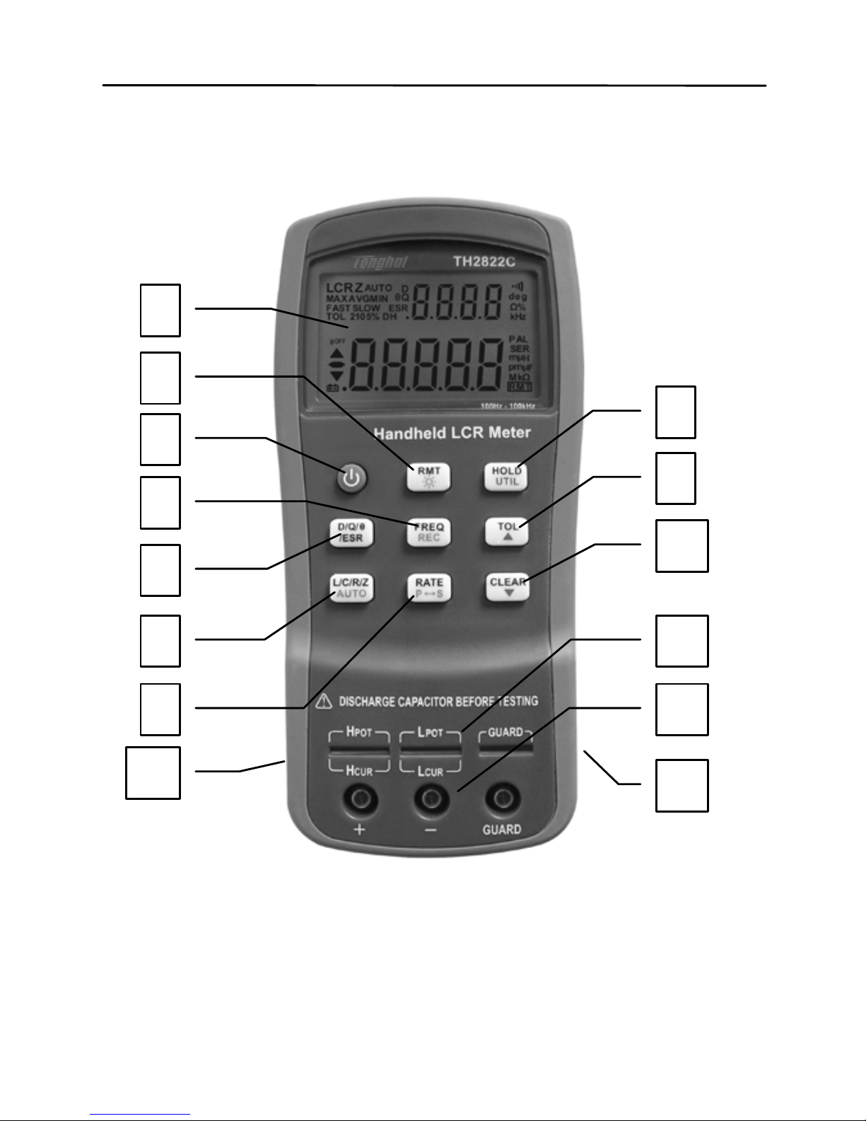
Figure 1 - Front Panel Display (model TH2822C shown)
1 2 3
5
6
8 4 7
13
9
10
11
12
14
Page 14

13
Front Panel Display Descriptions
1. LCD display
2. USB communication / *Back light button
3. Power ON/OFF button
4. Frequency and record mode selection
5. Secondary display mode (D /Q//ESR, etc.)
6. Primary display mode (L/C/R/Z, etc.)/ auto
LCR selection
7. Rate/equivalent mode selection
8. Hold mode/ utility menu
9. Tolerance mode/ utility arrow key
10. Open/short clear/ utility arrow key
11. 5-terminal test sockets (direct measurement
on lead components or use of test fixture)
12. 3-terminal test jacks (for use of Banana plugs
—Crocodile clip Test Leads)
13. Standard mini USB port (for remote control)
14. 12VDC external power input (use with an
external power adapter)
*Backlight is not included in TH2822.
NOTE: Refer to the adapter
’
s label for input
parameters of it. Rated output parameters is 12VDC
,
150mA,4mm.
NOTE: Use with included power adapter only or
purchase the specified adapters from Tonghui. Use
Page 15

14
with improper power adapters may damage
instrument.
NOTE: Internal battery supply will be
automatically cut off since the normal supply of
external power. If the battery is rechargeable
(TH2822C), the external power will charge the battery
simultaneously. TH2822C is installed an independent
charging controller---charging control is still done even
at the state of power-off.
WARNING: Before connecting an external
power adapter, b e sure that the polarity ma tches
the (+) and (-) labels as indicated inside the battery
compartment. If it is not installed correctly and
connected to an external power adapter, it might
cause severe damage to the instrument.
WARNING: If the battery is rechargeable
(TH2822C), please be sure that the polarity
matches the (+) and (-) labels as indicated inside
the battery compartment ant the battery is
rechargeable. DO NOT charge the nonrechargeable battery!
Page 16

15
Front Panel Buttons
With the exception of the power button, all front panel
buttons have specific colored labels on them. They
are all marked in black, blue, or orange color. Each
color has a specific representation, as described
below:
Black—the primary function,meaning that
function will be set or configured upon pressing it.
Orange—the secondary function, it means that
the function will be set or configured if that button is
pressed and hold down for 2 seconds.
Blue—the utility function, the function will be set
or configured if the UTIL button is pressed and hold
down for a long time. See “Utility Menu” section for
details.
NOTE: In the button operational instruction, we
will use the button name to express the button
operation without differentiating the type of button;
Pay attention to the difference between “long press”
and “press”.
Page 17

16
HOLD
FREQ
L/C/R/Z
/ESR
UTIL
CLEAR
RMT
P
S
TOL
RATE
AUTO
REC
D/Q/
θ
1 2 3 4
8
9 5
7 6
Figure 2 –Button Display (Model TH2822C shown)
Button Function Defi n ition
1. Power ON/OFF Button
2. Frequency/Record Mode Button
3. Remote Control/Bac klight Button
4. Readings Hold/Utility Menu Button
5. Tolerance mode/ Menu Selection Button
6. Clear/ Menu Selection Button
7. Rate/Equivalent Mode Button
8. LCR Primary Parameters/Auto LCR
9. Secondary Parameters Selection Button
Page 18

17
LCD Display Overview
LCR
ESR
MAXAVGMIN
θ
Q
AUTO
D
2105%
deg
kHz
PAL
SER
μ
H
p
F
μ
RMT
Mk
TOL
DH
n
n
@
OFF
Z
%
Ω
FASTSLOW
1
2 5 9 10
12
14
16
202127
28
29
8
3
23
24
25
4
15
11
13
6 7
22
17
18
19
Ω
26
Figure 3 - LCD Indicator Display
LCD Display Descriptions
1. LCRZ – Primary display indicator
2. MAX – Maximum reading indicator in the
record mode
3. AVG – Average reading indicator in the record
mode
4. MIN – Minimum reading indicator in the record
mode
5. AUTO – Automatic LCR indicator
6. θ – Phase angle indicator for secondary
display
Page 19
18
7. D – Dissipation indicator
8. Q – Quality factor indicator
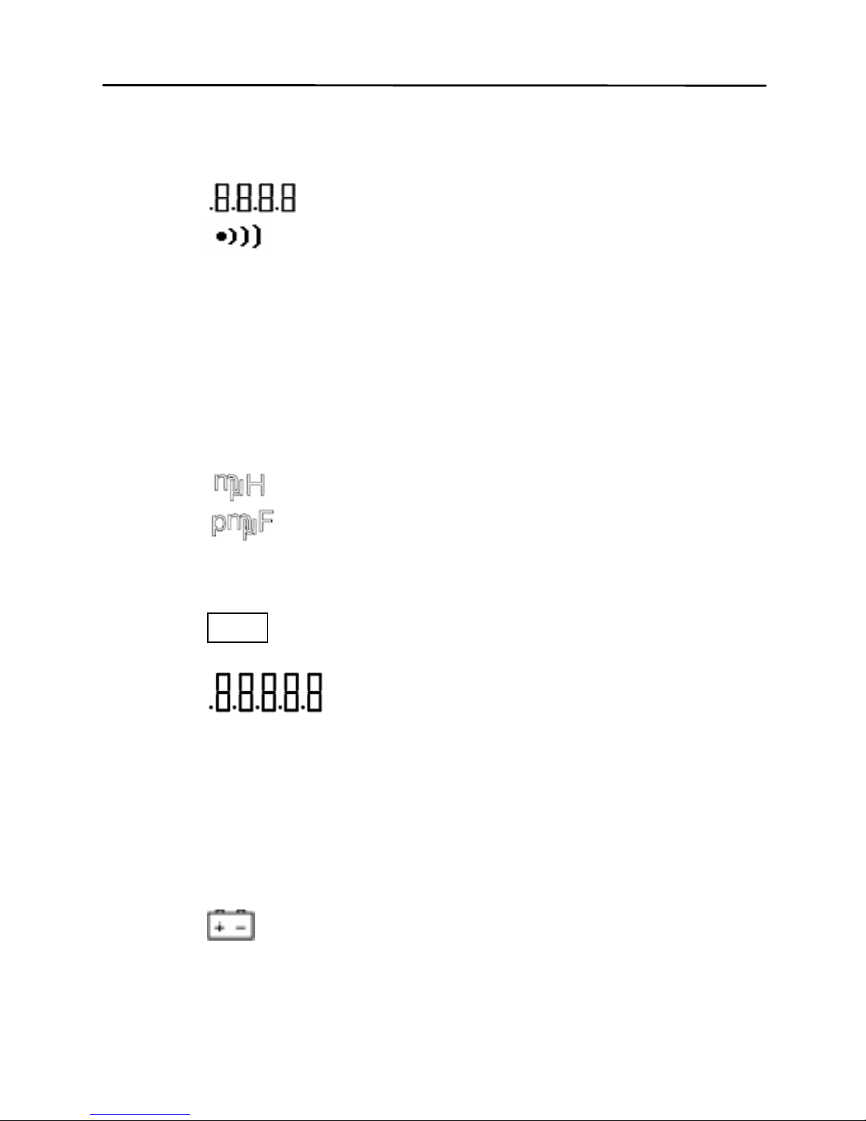
9.
– Secondar y display
10.
– Beeper tone indicator for tolerance
mode
11. deg – Phase angle (θ) units indicator
12. Ω – ESR(ohm) units indicator
13. % - Percentage indicator (in tolerance mode)
14. kHz – Frequency units indicator
15. PAL – Parallel mode indicator
16. SER – Series mode indicator
17.
– Inductance units (L) indicator
18.
–Capacitance units (C) indicator
19. MkΩ – Resistance(R) /impedance units
indicator
20. RMT – Remote mode indicator
21.
– Primary display
22. ESR – Series mode indicator for secondary
parameters
23. DH – Data hold indicator
24. SLOW – measuring rate indicator
25. 2105% - Limits indicator in tolerance mode
26. FAST- Fast measuring rate indicator
27.
– Low battery/charging indicator
28. @OFF –Auto power-off indicator
Page 20
19
29. TOL –Tolerance mode indicator
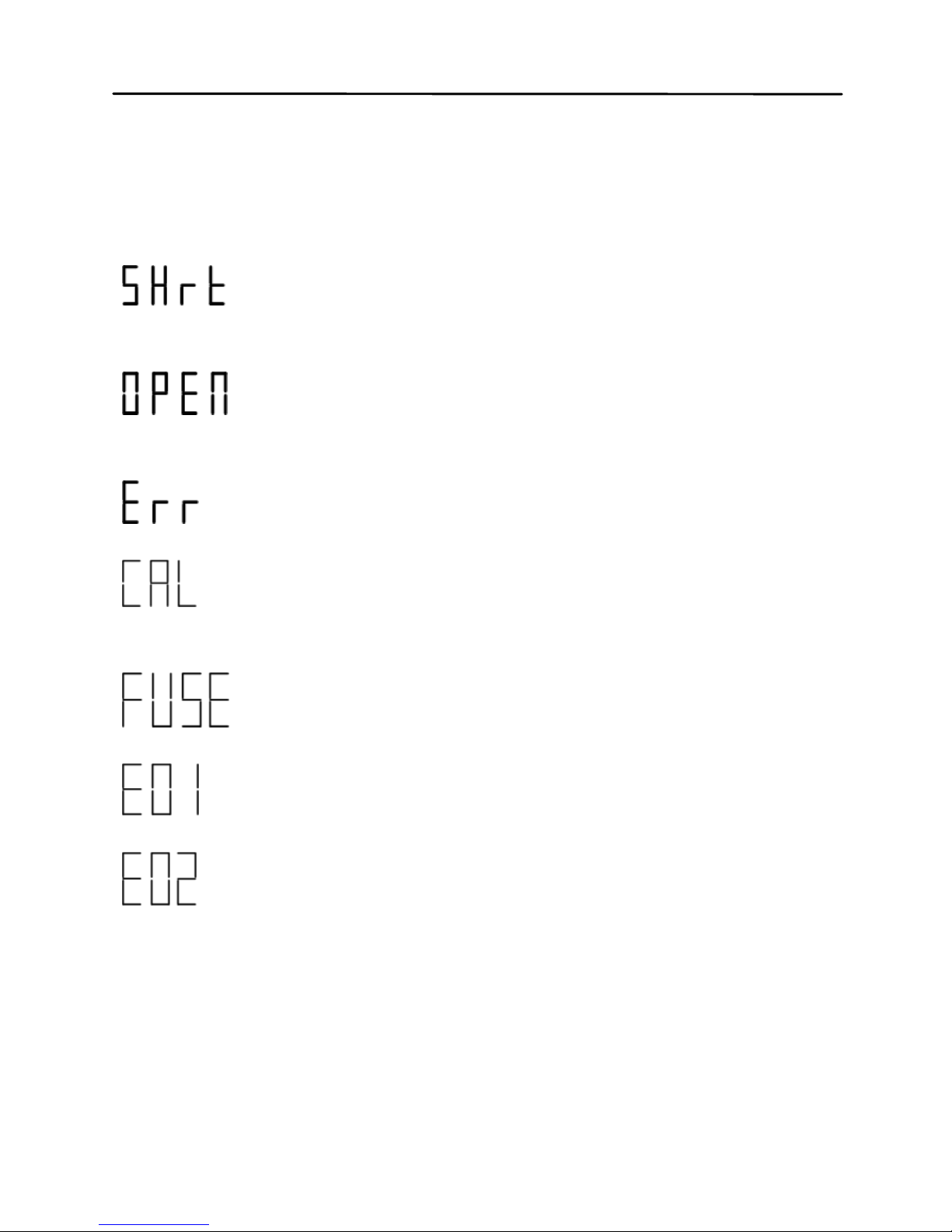
Special Display Indicators
Indicates short clear if you press the
CLEAR button
Indicates open clear if you press the
CLEAR button
Error indication
Indicates correction (open/short clear)
mode
Indicates damaged or open fuse
AD converter error(UNK)
AD converter error(END)
Test Port
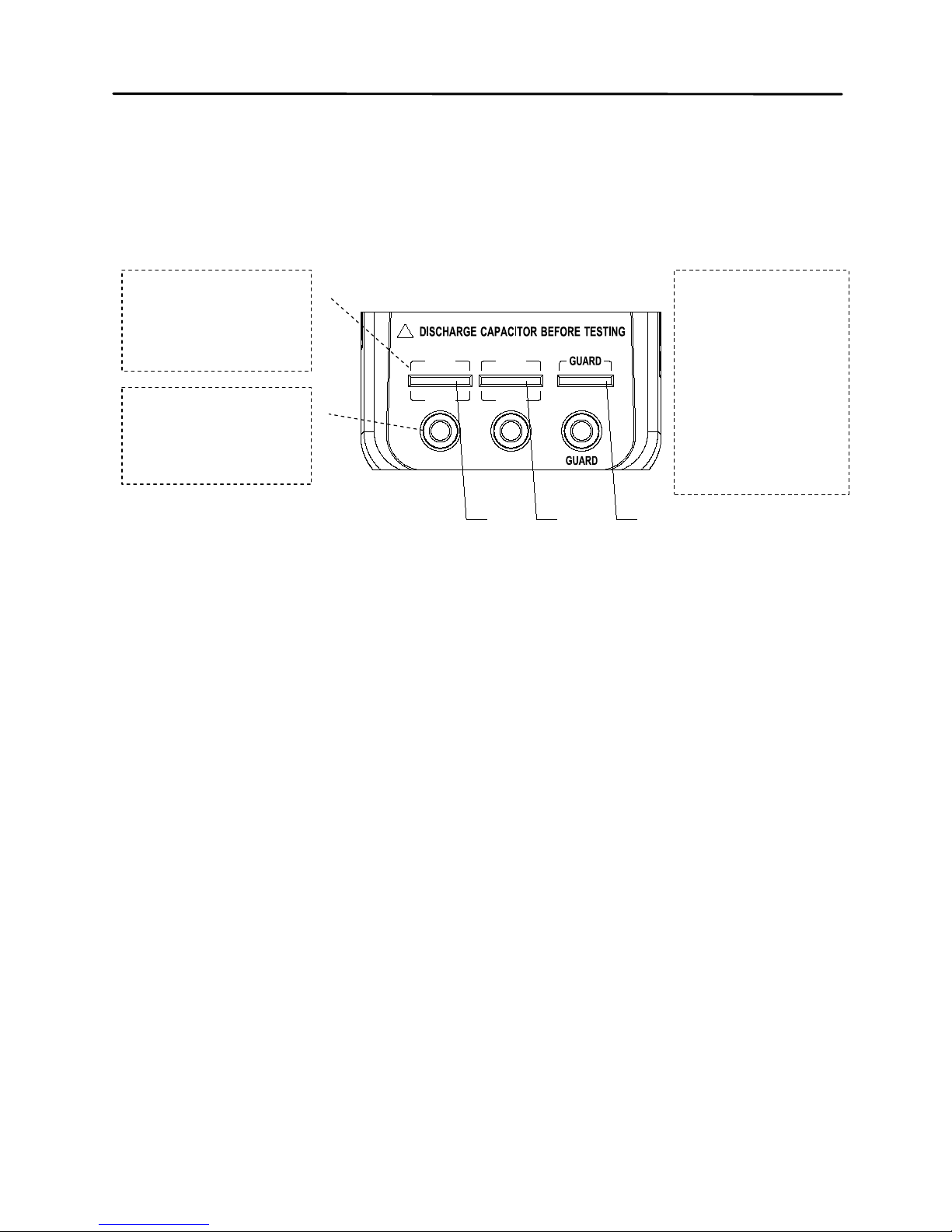
TH2822 series are creatively designed to combine 3terminal port and 5-terminal port, which makes the
Page 21
20
convenient test and highly accurate test realized in the
instrument.
+ -
!
H
CUR
L
CUR
H
POT
L
POT
1 2 3
Figure 4- test port
With the adoption of standard banana slots, the
instrument can use inexpensive banana plugcrocodile clip as the test lead, which make the test
quite convenient. However this configuration has low
testing accuracy.
For the improvement of accuracy when using external
testing leads, TH2822 series are designed with 5terminal testing slots and exclusive test fixture to
ensure complete external 4-terminal test and
measuring accuracy.
5-terminal
test slot
3-terminal
test port
1-Hight
Terminal
2-Low
Terminal
3-Guard
Terminal
Page 22

21
NOTE: TH26027A, TH26009C, TH 260 29C 4-terminal
test fixtures are optional for TH2822 series. Please
refer to relevant instrument accessories.
Powering Instrument
There are two methods to supply the instrument:
Battery and external power adapter. When the two
power modes are available, the external DC adapter
is prior to the battery. The two power modes can be
automatical l y switche d with out inter ru pti on.
Installing Battery
TH2822 series can adopt battery for power supply so
that you can take measurements whenever and
wherever without many preparations.
9V alkaline batteries used in TH2822/TH2822A are
non-rechargeable. Reference standard type is
IEC6LR61.
Page 23

22
TH2822C applies 8.4V rechargeable battery with
LH-200H7C as the reference type. Do not use nonrechargeab le batteries with the exception o f
emergency cases. The reason is that the charging
circuit will operate once the instrument is
connected to external power.
To Install the Battery:
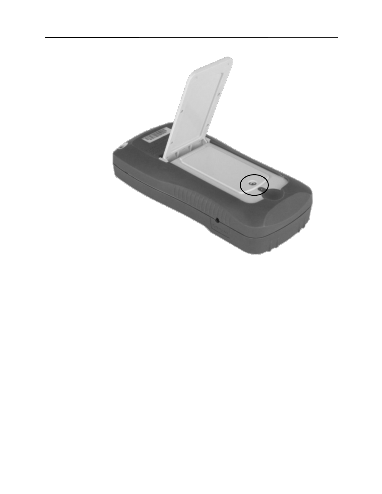
1. Open up the back-flip stand, and locate the
screw that tightens the battery compartment
cover as indicated in Figure 5. Use a
screwdriver to unscrew and remove the cover.
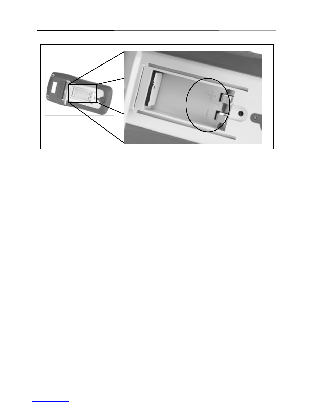
2. Insert proper battery into compartment. Note
the positive (+) and negative (-) terminals as
indicated inside the battery compartment
(See Figure 6). Be sure to insert the battery
with matching polarity.
3. Place the battery compartment cover piece
by sliding it into the top slid first. Place screw
at the bottom of the cover piece and tighten
down with a screw driver.
4. Push and hold down the power ON/OFF
button for 2 seconds to turn on the instrument.
Page 24
23
Figure 5- Back Cover
Page 25
24
Connecting External Power Source
Some models of TH2822 series are equipped with
standard external power adapters, which can use
external source.
WARNING: Use the included or specified adapter
only. Confirm p o wer p arameters be ones that
adapters require before use.
Figure 6- Battery Compartment
Page 26

25
To connect the adapter, do the following:
1. If a battery is installed, please check the
battery compartment again that the polarity of
the battery matches the polarity as indicated
by the labels inside the compartment.
WARNING: DO NOT, at any tim e, connect an
external power adapter when a battery is installed
incorrectly or a non-rechargeable battery is
inserted in a rechargeable instrument. Doing so
will damage the in strument and void its warranty.
2. Confirm that an appropriate power supply
connects to the adapter.
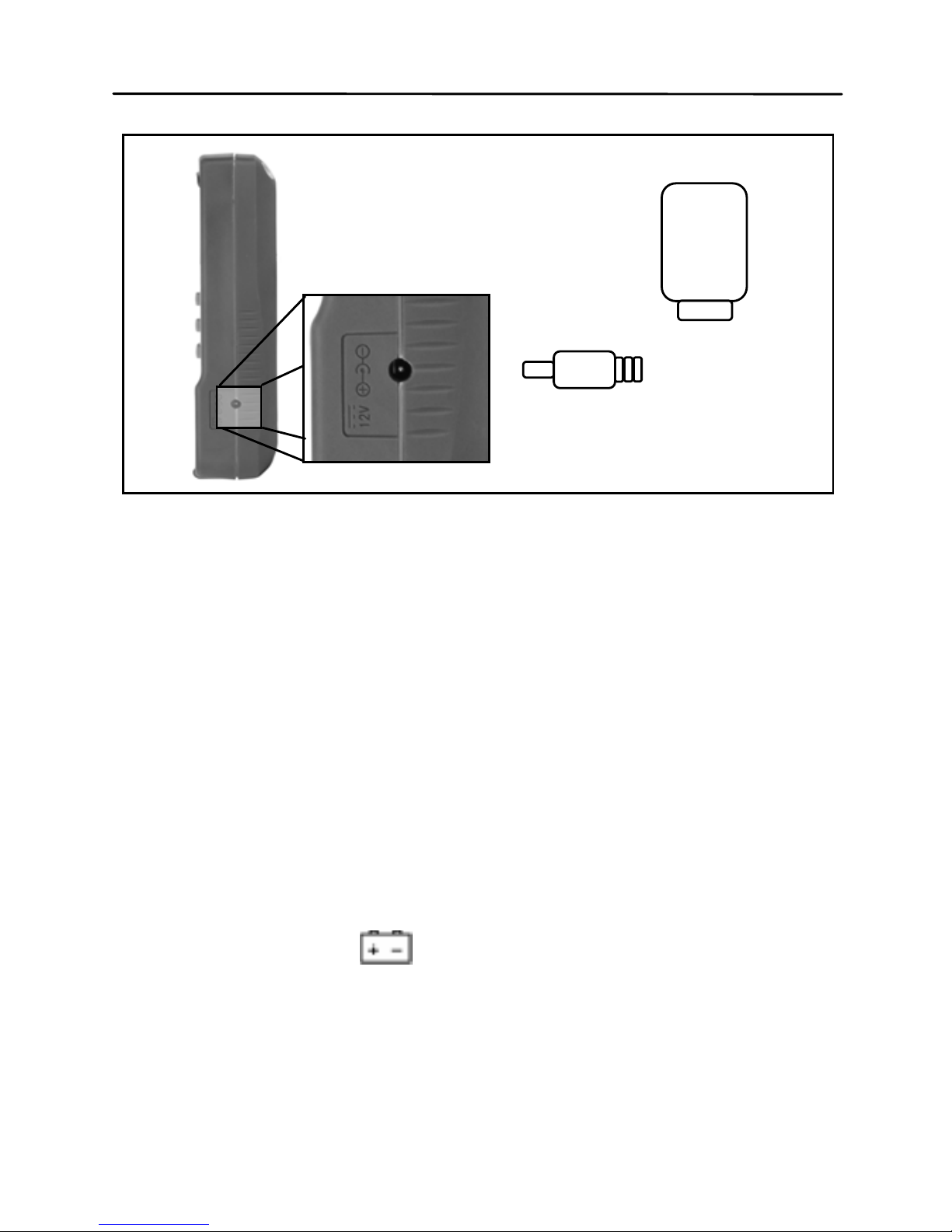
3. Connect the AC adapter connector into the
right side jack of 12VDC.
4. Connect the AC Adapter socket into an
electrical outlet.
5. Press and hold down the power button for
about 2s to turn on the meter.
Page 27
26
NOTE: The meter will automatically switch to
consume power from the AC adapter instead of the
battery when an AC adapter is plugged in and
consume the power normally. In this event, if the
battery insta lled c orrect ly is rec hargeab le (for inst ance,
TH2822C), charging controller will be driven at the
same time no matter the instrument is on or off.
Low Battery Ind ication
At the use of battery for power supply, if the display
starts flashing the
indicator, it means that the
battery voltage is below normal working voltage
(below 6.8V). It is highly recommended that the
battery be replaced as soon as possible before
12VDC Input
AC Adapter
Figure 7-Connecting AC Adapter to Meter
Page 28

27
continuing operation. See “Instal lin g Batt er y” for
instructions.
If the battery is rechargeable, when the
indicator
starts flashing, please charge the battery before
continuing operation. When the external source is
plugged in, the flash of
indicator indicates the
charging state.
Backlight Display
Only TH2822A/C meters have Backlight display that
can allow you to see the LCD display in dark
conditions, TH2822 doesn’t support backlight.
To turn on the back light, you should press the
button for a long time.
To turn off the back light, you should press the
button for a long time.
When Using Battery Power
When the meter is powered by using battery, the
brightness of the back light will automatically decrease
to conserve battery power. When the back light have
lightened for about 15 seconds, the brightness will
continuously decrease; and when the back light have
Page 29

28
lightened for approximate 30 seconds, the back light
will automatic all y turn of f .
When Using Exter n al Power
When the meter is powered using an external AC
adapter, once the back light is turned on, it will stay at
its maximum brightness continuously and will not
automatical l y turn off . Unplugg ing the ex ter na l po wer
to use battery power, the back light will decrease its
brightness and automatically turn off.
Charge Display
The power circuit of TH2822/A is non-rechargeable.
When the external power adapter is plugged in, the
power mode will automatically switched and the
battery power circuit will be cut off.
TH2822C is equipped with rec har gea ble circuit. When
the external power adapter is connected, the built-in
rechargeable battery will be charged automaticall y
and the power mode will be switched to external
power supply.
Single charge circle is about 80 minutes and charge
current is approximate 40mA. If a battery is full
charged, the charge wi ll be automaticall y shut off ;
Page 30

29
instead, the battery will be charged again after a
charge circle.
NOTE: A new charge circle will begin as soon as an
external power is connected.
WARNING: If the instrument has rechargeable
circuit, DO NOT connect to an external power
when a non-rechargeable battery is installed.
Doing so will cause the burst of the battery.
: It indicates low power of battery if not
connect to external power; if instrument is
connected to external power, it means the
charging state.
Page 31

30
Operation Instruction
Data hold mode (HOLD)
The data hold function allows the user to freeze the
display data. The data displayed on LCD will not
update upon the phase of test until data hold is turned
off.
Turn On Data Hold
To use data hold, press the HOLD button. The “DH”
indicator will display on the screen when data hold is
active. At this moment, primary and secondary
displayed on LCD are the testing results before the
press of HOLD button.
Turn Off Data Hold
To disable the data hold, press the HOLD button
again. The “DH” indicator wil l disappear on the scr een,
and meter will remain in normal operation mode.
Page 32
31
Data Record Mode (REC)
If the data stability of tested components is poor and
the data fluctuates in a range, data record mode can
aid the reading of data.
This mode is used for dynamically recording
maximum, minimum, and average values in a range.
Enable Static Recording
Press and hold down the REC button for a long time
to enter the data recording mode. The display should
indicate “MAX AVG MIN” simultaneously, which
indicates the meter is in static recording mode.
Using Static Recording
There are four different modes that can be selected in
static recording. Per press of the REC button (in
recording mode, FREQ will disable), the modes will
change and repeat in the following order:
Recording Mode
Maximum Mode Minimum
Mode
Average Mode
Page 33

32
Recording Stat e
This is the default mode when enabling static
recording. In this mode, LCD will display “MAX AVG
MIN” indicator. In a relatively stable range of test data,
a beep tone will sound once a recording has been
stored.
NOTE: When the data fluctuation range is upwards of
1%, data record will dynamically be refreshed.
Maximum Display
Press REC button until the “MAX” indicator is shown
on display. This indicates that the value in the primary
display represents the recorded maximum value.
Minimum Display
Press REC button until the “MIN” indicator is shown
on display. This indicates that the value in the primary
display represents the recorded minimum value.
Page 34

33
Average Display
Press REC button until the “AVG” indicator is shown
on display. This indicates that the value in the primary
display represents the recorded average value.
Disable Static R eco rding
To exit this mode, press and hold the REC button for
a long time. All the “MAX”, “MIN”, or “AVG” indicator
will disappear on LCD.
NOTE: Changing the type of test parameters will
automatically turn off static recording.
L/C/R/Z Select Mode
To select measurement mode, you should select
primary parameter first.
Each press of the L/C/R/Z button, the parameter will
change and repeat as the following modes:
L (inductance), C (capacitance), R (resistance), and Z
(impedance).
NOTE: After changing primary mode, secondary
display indicates the present frequency. If it is
required to display corresponding secondary
parameters, press the secondary button.
Page 35

34
D/Q/θ/ESR Select Mode
If necessary, press the D/Q/θ/ESR button to select
secondary parameters.
Each press of the D/Q/θ/ESR button, the following
modes will be displayed on the screen:
D (Dissipation factor), Q (Quality factor), θ (Phase
angle), and ESR (Equivalent series resistance).
Test Frequency (FREQ)
TH2822 series handheld LCR meters apply AC signal
to DUT for measurement. Frequency is among the
main parameters of AC signal. By the presence of
component’s non-ideality and distributed parameters,
the effect of distributed parameters of test port and
test lead, the test frequency used on the same
component might ca use different tes t r es ult. Therefor e,
a proper frequency should be selected before test.
Selecting Frequency
Change the test frequency, push the FREQ button. If
the secondar y displa y does not indicate t he frequ ency,
it will display the actual operating frequency when you
press FREQ. If the secondary display indicates
frequency, at each press of the FREQ button, the
Page 36

35
meter will change among the following selectable
frequencies:
TH2822: 100Hz/120Hz/1kHz
TH2822A:100Hz/120Hz/1kHz/10kHz
TH2822C:100Hz/120Hz/1kHz/10kHz/100kHz
Tolerance Mode (TOL)
The tolerance mode is specifically used for
component sorting purposes. In tolerance mode,
secondary display indicates the range of percentage.
Tolerance mode, nominal value and sorting limit just
come into play on prim ar y param eters . The selec table
ranges for sorting are as follows: 1%,5%,10%,
20% (20% is not for TH2822).
When entering tolerance mode, the data indicated in
the primary display will be recorded as nominal value.
Displayed value in percent age is:
100*(Mx-Nom)/Nom%
Where, Mx is the test value displayed on the primary
display; Nom is the recorded nominal value.
The percentage value is used for sorting.
Page 37

36
Use Tolerance M o d e
To use the tolerance mode as the process shown
below:
1. Select the desired primary measurement
mode by pressing L/C/R/Z button.
2. Configure the proper test frequency and
series/parallel equivalent mode.
3. Perform the operation of CLEAR appropriately
if necessary.
4. Test standard implements or components with
accurate and reliable measured value.
5. Once the desired measured reading is
displayed, press the TOL button once to store
the reading as the nom inal value. At this point,
the “TOL” will be displayed on the screen,
indicating that th e toleranc e mode is ac tivated .
A percentage m ode will be sho wn in the
secondary mode to indicate the percentage
deviation.
NOTE: Before the press of TOL button, the
primary parameter indicated on LCD in any
mode can be taken as the nominal value,
including data ho ld, MAX, MIN , AVG data
recording, etc.
6. If sorting is not necessary, you can skip this
step. If it is necessary, by pressing the TOL
button you can select the range of 1%, 5%,
Page 38

37
10% or 20%, which will be sho wn on LCD
accordingly.
7. Changing test component, an audible tone will
be heard. One single “beep” or tone means
the component is within tolerance. Three
“beeps” or tone means the component is out
of tolerance.
WARNING: Be sure that the capacitor has
been fully discharged before its test, or the
instrument mig h t b e damaged.
Disable Tolerance Mode
Long press of TOL button will disable tolerance mode.
NOTE: Changing the test frequency, primary function,
or secondary function will automatically disable
tolerance mode.
Auto LCR Mode
Auto LCR function will automatically select the
correspondi ng primary and secondary parameters and
suitable series/parallel equivalent mode of L, C, R.
The selection is done by judging the impedance
Page 39
38
property of component according to the test result. It
is quite convenient for the measurements of mixed
and unknown components.
Enable Auto LCR Mode
Long press of AUTO button will activate auto LCR
mode. The “AUTO” indicator on LCD indicates that
auto LCR mode is activated.
In auto LCR mode, the match of secondar y param eter
with primary parameter is shown as below:
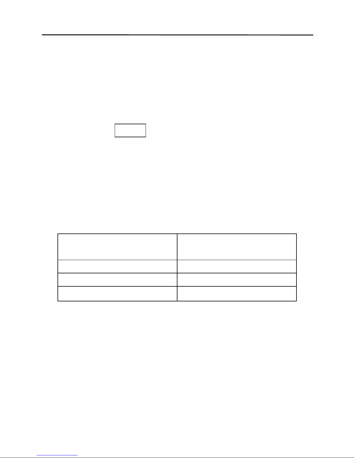
Table1-Matching relations between primary and
secondary parameters in auto LCR mode
Primary Parameter
Secondary
Parameter
Capacitance (C)
Dissipation (D)
Inductance (L)
Quality Factor (Q)
Resistance (R)
Phase Angle (θ)
In auto LCR mode, series or parallel equivalent mode
is selected in accordance with the magnitude of
impedance. Parallel mode is selected at high
impedance and series mode at low impedance.
Page 40

39
Disable Auto LCR Mode
Long press the AUTO button again will disable auto
LCR mode. In addition, this mode will not continue
through changing the primary and secondary modes,
series/parallel equivalent mode and frequency mode.
“AUTO” indicator on LCD will disapp ear when auto
LCR mode is turned off.
Measurement Rate (RATE)
There are two selectable measurement rates in this
instrument: fast and slow. The rate of fast
measurement is about 4~5times/sec and slow
measurement is approximate 1.5 times/sec. The
stability of slow measurement is higher than fast
measurement.
The fast and slow rates can be directly switched by
pressing RATE button. “FAST” indicator will be
displayed on LCD at fast rate and “SLOW” indicator at
slow rate.
Series/parallel Equivalent Mode
For the presence of non-ideality and distributed
parameters of components, actual components are
usually equivalent to combined network of ideal
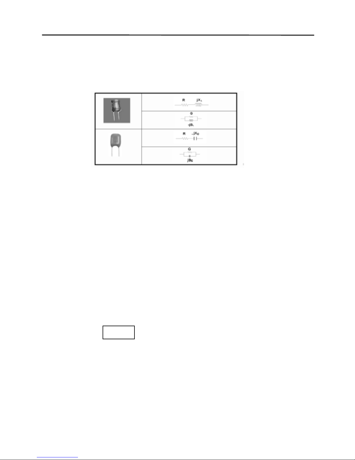
components. In general, there are two simple
Page 41
40
equivalent models used in LCR meters, which are
series model and parallel model.
Figure 8-Series and Parallel Equivalent Models of
Inductors and Capacitors
Appropriate equivalent modes could help to gain
better measurement results. Generally, Series mode
is better for components with low impedance (blow
100Ω),while parallel mode for components with high
impedance (over 10kΩ). For the components with the
impedance between the two limits, equivalent mode
has little effect on the testing result.
Selecting Measur em ent Mod e
Long press P<->S button, “PAL” on LCD ind icates
parallel equivalent mode and “SER” means series
equivalent mode.
Page 42

41
Default Equiva lent Mode
When select primary parameter, equivalent mode
varies with primary parameter:
For capacitors and resistors, default equivalent
mode is PAL; for inductors, is SER.
Utility Menu (UTIL)
The LCR meter has a built-in utility menu that allows
you to configure some user preferences and settings.
The buttons used to set and control the menu are
colored in blue. There are three buttons: UTIL, ,
. User can configure the beep tone, auto power-off
timing, store/restore power-on state, view the battery
voltage, etc.
Entering Utility Menu
Long press UTIL button wil l enter utility menu. Prim ar y
display is menu option and secondary display is the
current settings or parameters configured for the
selected option. After the entrance into utility menu,
the default menu option display will show “bEEP”.
Page 43
42
Configuration and Settings
The following contents are included in the utility menu:
Table 2-Utility Menu Options and Settings
Menu Options Settings/Parameters
bEEP
ON / OFF
AoFF
5 / 15 / 30 / 60 / OFF
PuP
PrE / Set
dEF yES / NO
bAtt Battery Voltage
Uses of these menu options are as follows:
Control beep sound( bEEP)
Set auto power-off(AoFF)
Set power-up state(PuP)
Reset to default settings(dEF)
Indicate battery voltage(bAtt)
By default, press the button UTIL to change or select
a different menu option. To change the settings or
parameters, use the and arrow keys. For each
UTIL button press, the meter will traverse through
each menu options and will repeat itself in the
following order:
bEEP AoFF PuP dEF bAtt
Page 44

43
NOTE: The change of settings has different
application effects in accordance with different exiting
mode. See “Exit Utility Menu” section (Saving and
Exiting, Exiting without Saving) for details.
Beep Sound Setup (bEEP)
The “bEEP” menu option allows the user to enable or
disable the beep sound for every key press.
NOTE: This option only disables the beep sound for
each key press. It does not affect the beep sound for
“Tolerance” mode and “Static Recording”, as well as
the “auto power-off” warning.
Use the and arrow keys to choose ON or OFF.
This setting will be immediately effective. But this
state will not saved if choose “Exiting without Saving”;
“Saving and Exiting” should be implemented if this
setting needs to be effective after restarting.
Default setting: ON.
Auto power-off Setup(AoFF)
The “AoFF” menu option allows the user to select the
auto power-off timer. The available timer settings are:
5min/15min/30min/60min/OFF. When the primary
Page 45
44
display shows “AoFF”, push the and arrow keys
to select the timer setting. The settings will be shown
on the secondary display as Table 3.
When AoFF is effective, this timer is always counting
continuously; when the configured time is up, the
meter will make an audible “beep” sound continuously
to remind the user of prompt auto power-off. Before
auto power-off, pressing any button will reset the timer
count.
NOTE:
Auto power-off is effective only for battery
power.
NOTE: When auto power-off is efficient, the display of
“@OFF” indicates the operation of timer.
NOTE: Auto power-off will not work temporally in TOL
mode, REC mode and RMT mode. It will be activated
after exiting of above modes.
Table 3- Auto Power-off Options
Secondary Display
Representation
5
5 minutes
15
15 minutes
30
30 minutes
60
60 minutes
OFF
Manual power off only
Page 46

45
The setting will be immediately effective. But this state
will not saved if choose “Exiting without saving”;
“Saving and exiting” should be implemented if this
setting needs to be effective after restarting.
Default Setting: 5
Power-up State (PuP)
The “PuP” menu option allows user to configure
the power-up state of the LCR meter, allowing user to
restore settings saved into internal EEPROM memory
at power-up. The storable settings are as follows:
• Primary function mode (e.g. L/C/R)
• Secondary function mode (e.g. D/Q)
• State of auto LCR
• Series/para llel equ iv al ent mode
• Test frequency
• Tolerance mode
• Reference value for Tolerance mode
• Measurement rate
In the utility menu, Press the and arrow keys
to select “PrE” or “SEt”. PrE means to preserve the
previous setting while SEt means to save the current
parameter, that is, cover the previous data.
Page 47

46
NOTE: Exiting mode decides whether to implement
SEt. At “Exiting without saving”, SEt is ineffective;
while at “Saving and Exiting”, SEt setting will be
effective.
Default Setting: PrE
Configure and Sa ve Power-up State
Procedure to configure and save po wer -up state is as
follows:
1. Before entering into the utility menu, configure
all the measurement parameters firstly, such
as frequency, primary and secondary
parameters. If the meter is currently in the
utility menu, exit first and enter into utility
menu after measuring setup.
2. Press UTIL button for a long time to enter into
utility menu.
3. Push the UTIL button to traverse through the
utility options until you see “PuP” on the
primary display.
4. In order to save the current meter settings for
power-up state into internal memory, use
Page 48

47
either or button to change the settings
so that the secondary display shows “Set”.
5. Press the UTIL button to check whether other
desirable setups have already been set. With
all settings done, exit the menu by long press
of the UTIL button.
6. The meter has now saved all current settings
into internal memory. At next power-up, the
meter will turn on and recall the saved
settings.
NOTE: The meter allows one set of settings to be
stored into memory. Therefore, the same
procedure is used to overwrite previously stored
settings into memory.
Prevent Overwrite of Stored Settings
In the utility menu, the “PuP” option default setting is
always “PrE”. If it is required to overwrite previously
stored settings for power-up state, the option should
change to “Set”. Therefore, when entering the utility
menu, be sure not to change to “Set” to prevent
overwriting any previously stored power-up settings.
Page 49

48
Reset Default Settings (dEF)
The “dEF” option is used to reset the current
measuring setup and optional settings in utility menu
to default settings. These default settings are as
below:
Page 50
49
Table 4 - Instrument Default Settings
Settings Default Configuration
Primary Function C (capacitance)
Secondary Function None (frequency)
Auto LCR function Off
Equivalent Met hod SER (series)
Measurement Frequency 1kHz
Measurement Speed Slow (SLOW)
Tolerance Mode Off
Beep Sound On
Auto Power-off Timing 5 minutes
Stored Measurement
Setup
clear
Stored Utility Menu
Option
clear
Page 51

50
In “dEF” option, push either or button to
choose “NO” or “yES”. “NO” means the instrument will
not be set back to default. “yES” indicates to reset all
settings to defau lt and to cl ear pre viousl y stor ed setup .
Default Setting: No
NOTE:
Exiting mode also dec id es whether or not to
perform “yES” function. At the use of “exiting without
saving”, “yES” is ineffective; when “saving and exiting”
is selected, restore operation will be efficient.
NOTE: In the case where “PuP” is set to “Set” and
“dEF” is set to “yES” simutaneously, the “PuP” setting
has priority over the “dEF” setting. This means the
instrument will not be set back to default upon saving
and exiting the utility menu. Instead, the power-up
settings will be stored and will be recalled upon the
next power-up of the instrument.
Indicate battery voltage(bAtt)
When menu option changes to “bAtt”, the secondary
display will indicat e battery voltage that is for
reference instead of for operational function.
Page 52

51
Exit Utility Menu
There are two methods for exiting the utility menu:
Saving and Exitin g, Exiting without Saving. The
former saves all the changed settings before exiting,
and the latter exits the menu without saving any
changes.
Saving and Exiting
To save all utility menu option settings and to exit the
menu, press and hold down the UTIL button for a long
time. After this, the meter will exit the menu. Then
PuP and dEF will be performed and all settings will be
saved.
“Saving” means that corresponding settings will be
saved in the built-in non-volatile memory. Therefore,
data will not lose at the time of power-off and can be
used at the time of next power-on.
Exiting Without Saving
If user decides to exit the utility menu without saving
the optional settings, and gives up the operation of
“PuP” and “dEF”, it can be done by simply pressing
Page 53

52
any front panel buttons except UTIL, , and
POWER. PuP and dEF operation will be ineffective.
Settings, such as “bEEP” and “AoFF” will not be
saved in the non-volatile memory but still be
temporarily efficient before power-off.
Clear Functions (CLEAR)
There are two functions under CLEAR: Open Clear
and Short Clear. Clear can decrease the distributed
error caused by test leads, for instance, short clear
can reduce the effects of contact resistors and test
leads and open clear will minimize the influence of
distributed capacitors and resistors on testing high
impedance components.
Enter Clear Mode
For convenience, open clear and short clear are
designed to share a button. By pressing the CLEAR
button, the meter will automatically choose either
OPEN clear or SHORT clear.
Page 54
53
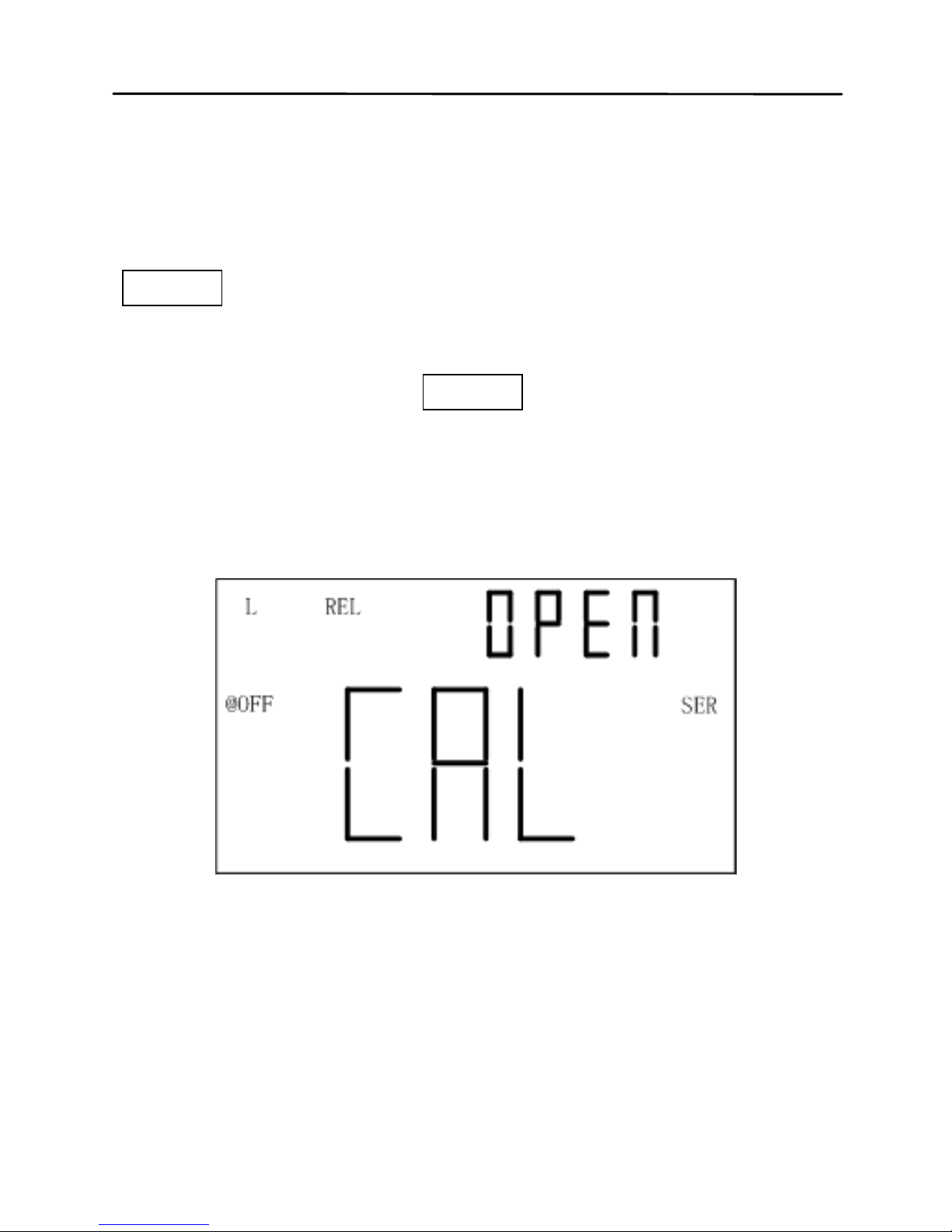
Open Clear
First select frequency to clear and keep test clip and
test slot be open. Enter into clear by the press of
CLEAR, and a moment later the OPEN indicator will
appear on secondary display after the automatic
measurement judging. If user decides to perform open
clear, another press of CLEAR should be done.
NOTE:“----” indicator on secondary display indicates
that test terminal is out of open state and open clear
cannot be performed.
Figure 9 - Open Clear
Page 55
54
Short Clear
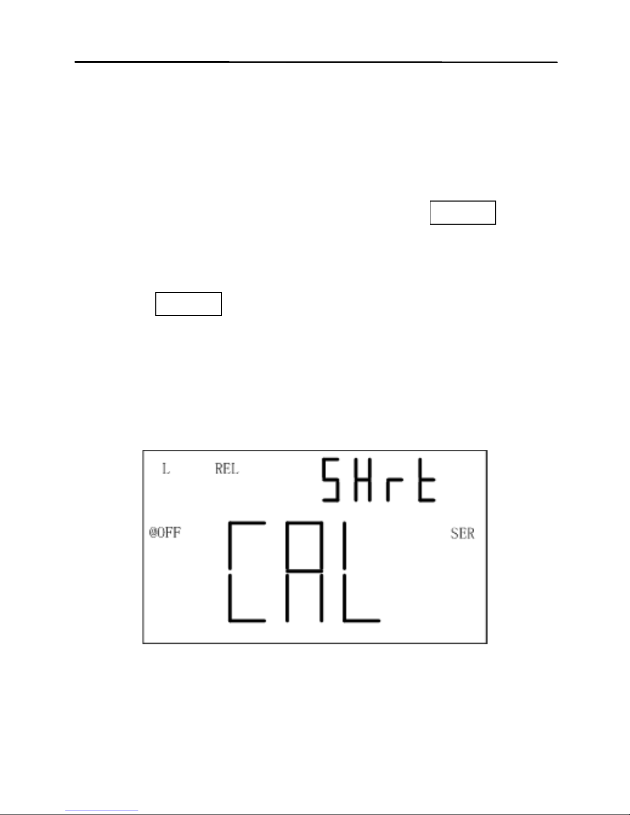
First choose test frequency to clear and then insert a
short plate to test slot. If SMD test tweezers or test
clip is used, the short plate should short the test
terminal. Enter into clear by the press of CLEAR, and
a moment later the SHrT indicator will appear on
secondary display after the automatic measurement
judging. If user decides to perform short clear, another
press of CLEAR shou ld be done .
NOTE: “----” indicator on secondary display indicates
that test terminal is out of short state and short clear
cannot be performed.
Figure10-Short Clear
Page 56

55
Quick Clear Procedure
Below is an example of steps to do open or short clear:
1. Select the primary and secondary function
mode for measurement;
2. Select test frequency;
3. Select equivalent mode;
4. Keep the test terminal open to perform open
clear;
5. Short the test terminal to perform short clear;
6. Connect DUT to start testing after clear.
NOTE:
1. Clear data is just temporarily stored in RAM,
which means that the data will loss after
power-off. Therefore, “clear”, prior to
measurement, should be first done after
power-on.
2. Clear data is stored under different frequency,
thus they will be still valid at the change of test
frequency (for instance, under the frequency
of 1kHz, the meter has been cleared; and
when the frequency is back to 1kHz, there is
no need to clear again.)
3. Clear is not concerned with test parameters
and series/parallel equivalent mode. In
Page 57

56
accordance with adv anc e d impedance
network principle, the instrument performs
clear operation. Though the complex
impedance is cleared, the displayed
parameter is just one of the elements of
impedance, so it is cleare d too.
4. After a long time of continuous use, the meter
will be affected by the temperature
environment and test fixtures, test leads and
contact resistance will change. It should be
necessary to clear once more according to
specific conditions so as to meet the
requirement of accuracy.
Remote Control (RMT)
When the RMT button is used for remote
communication, please see “REMOTE
COMMUNICATION” section for details.
Fuse Detection
The meter has an internal fuse in the test signal
terminal that protects the internal components from
severely damaging the instrument. When the fuse is
Page 58
57
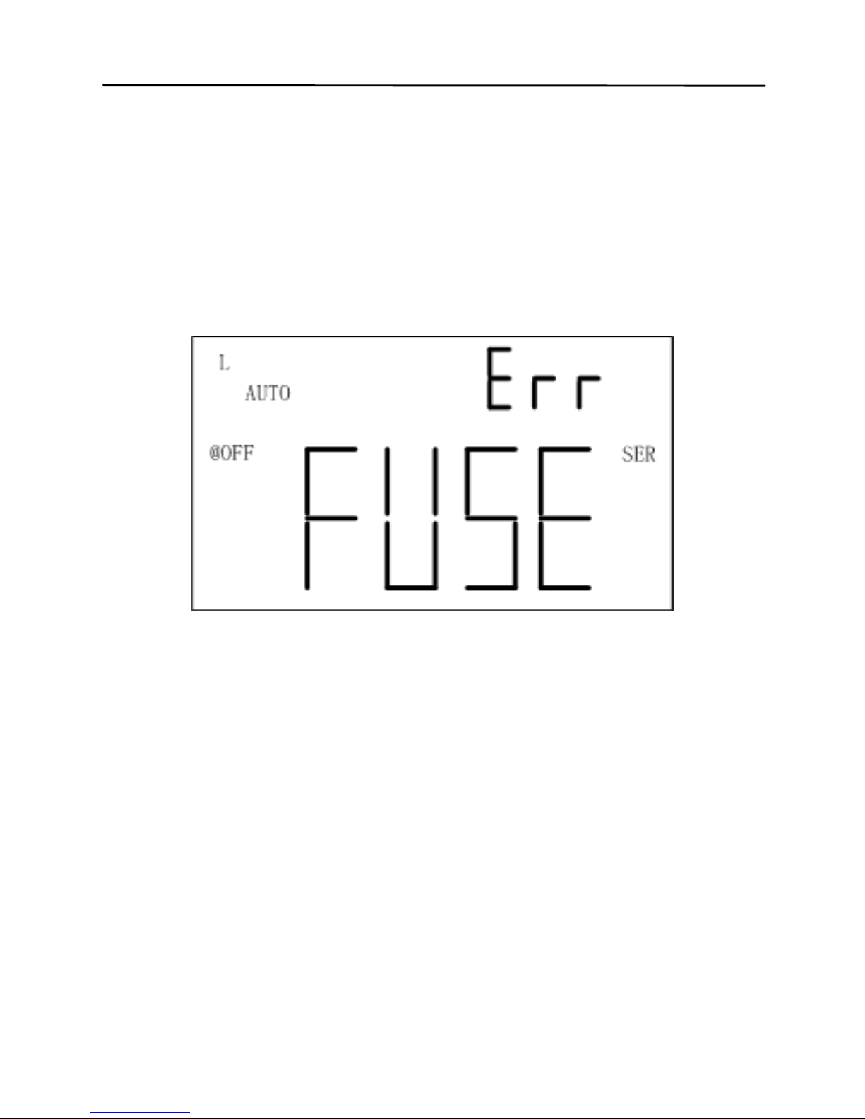
burned out, the “FUSE” indi c ator will app ear on the
primary display and an internal “beep” will sound
continuously. In this situation, none of the function
buttons can be operated and all other meter functions
will be disabled.
Figure 11-Fuse Display
In the event that the above screen is displayed, the
instrument should be powered off. If this does not
power off the meter, remove external AC adapter if
that is used and/or remove the battery from the
battery compartment. Please contact after-sale
department of our company or appointed distributor
for the change of fuse or maintenance.
Page 59

58
NOTE: Both fuse damage and none output of test
signal caused by signal source fault will make “FUSE”
alarm.
Quick Start Guide
CAUTION
• Do not measure a capacitor that is not fully
discharged. Connecting a charged or partially
charged capacitor to the input terminals will
damage the instrument.
• When measuring an on-board component within a
circuit, the circuit must be powered off before
connecting the test leads.
• When used in a dusty environment, the instrument
should be wiped and cleaned regularly. The
electrical conductivity carried by the accumulated
dust will eventua lly have an eff ect on th e use of the
meter.
Page 60

59
• Do not leave the instrument exposed to explosive,
direct sun-lighting and overheating environments.
• Before removing the cover, ensure that none DUT
is connected to the meter and the instrument is
disconnected from any circuit and is powered OFF.
NOTE: To achieve optimum precision, please refer to
“Clear Function” for details bef ore tes ti ng.
Inductance Measurement
1. Press the POWER button for a long time to turn
on the instrument.
2. Press the L/C/R/Z button until “L” is displayed on
the screen to select inductance measurement
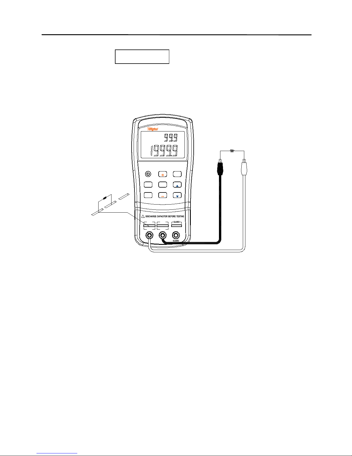
3. Insert an inductor into test slots or connect a
tested inductor through a proper test accessory
(e.g., banana plug-crocodile clip test leads, test
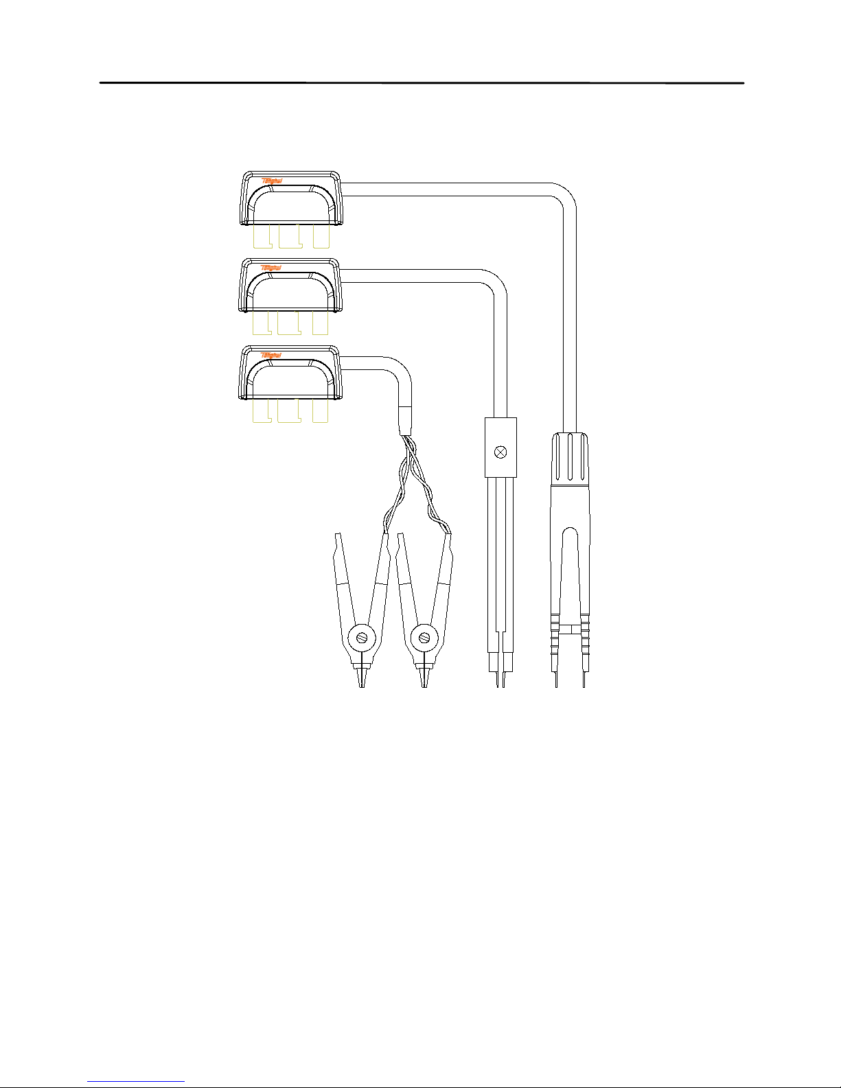
fixture or S MD t es t t we e zer s ). See figures 12. And
figure 13 shows the optional 4-terminal test
accessories.
4. Press the FREQ button until the desired test
frequency is displayed on screen.
Page 61
60
5. Press the D/Q/θ/ESR button to select the desired
secondary parameter.
6. Read the readings on LCD for inductance
measured values.
+ -
!
H
CUR
L
CUR
H
POTLPOT
Handheld LCR Meter
100Hz - 100kHz
L
Q
AUTO
SER
μ
H
@
OFF
HOLD
FREQ
L/C/R/Z
/ESR
UTIL
CLEAR
RMT
P
S
TOL
RATE
AUTO
REC
D/Q/
TH2822C
θ
Figure 12- Inductance Measurement
Below are TH26027A,TH26009C,TH26029C 4terminal test accessories:
Page 62
61
TH26029C
SMD KELVIN TWEEZER
H
CURLCUR
GUARD
TH26009C
SMD KELVIN TWEEZER
H
CURLCUR
GUARD
H
CUR
L
CUR
GUARD
TH26027A
KELVIN CLIP
Figure 13- 4-termin al Test A ccess or ies
Page 63

62
Capacitance Measurement
WARNING: Before testing, ensure that the
tested capacitor has been fully discharged.
1. Press the POWER button for a long time to turn
on the meter.
2. Press the L/C/R/Z button u ntil “C” is displayed on
the screen to select capacitance measurement.
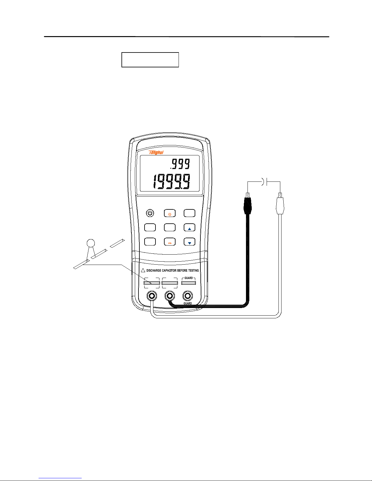
3. Insert a capacitor into test slots or connect a
tested capacitor through a proper test accessory
(e.g., banana plug-crocodile clip test leads, test
fixture or SMD test tweeze rs). See figure 14. And
figure 13 shows the optional 4-terminal test
accessories.
4. CAUTION: Before inserting a capacitor or
capacitive component into the input slots or
terminals, be sure to fully discharge the
component. Some larger capacitive
components may take longer to discharge. In
these cases, please allot enough time for a full
discharge. If improper discharging of the
component is done, it will damage the input
terminals of the meter.
5. Press the FREQ button until the desired test
frequency is displayed on screen.
Page 64
63
6. Press the D/Q/θ/ESR button to select the desired
secondary parameter.
7. Read the readings on LCD for capacitance
measured values.
+ -
!
H
CUR
L
CUR
H
POT
L
POT
Handheld LCR Meter
100Hz - 100kHz
C
AUTO
D
PAL
p
F
@
OFF
HOLD
FREQ
L/C/R/Z
/ESR
UTIL
CLEAR
RMT
P
S
TOL
RATE
AUTO
REC
D/Q/
TH2822C
θ
Figure 14- Capacitance Measurement
Page 65

64
Resistance Measurement
1. Press the POWER button for a long time to turn
on the instrument.
2. Press the L/C/R/Z button u ntil “R” is displayed on
the screen to select inductance measurement.
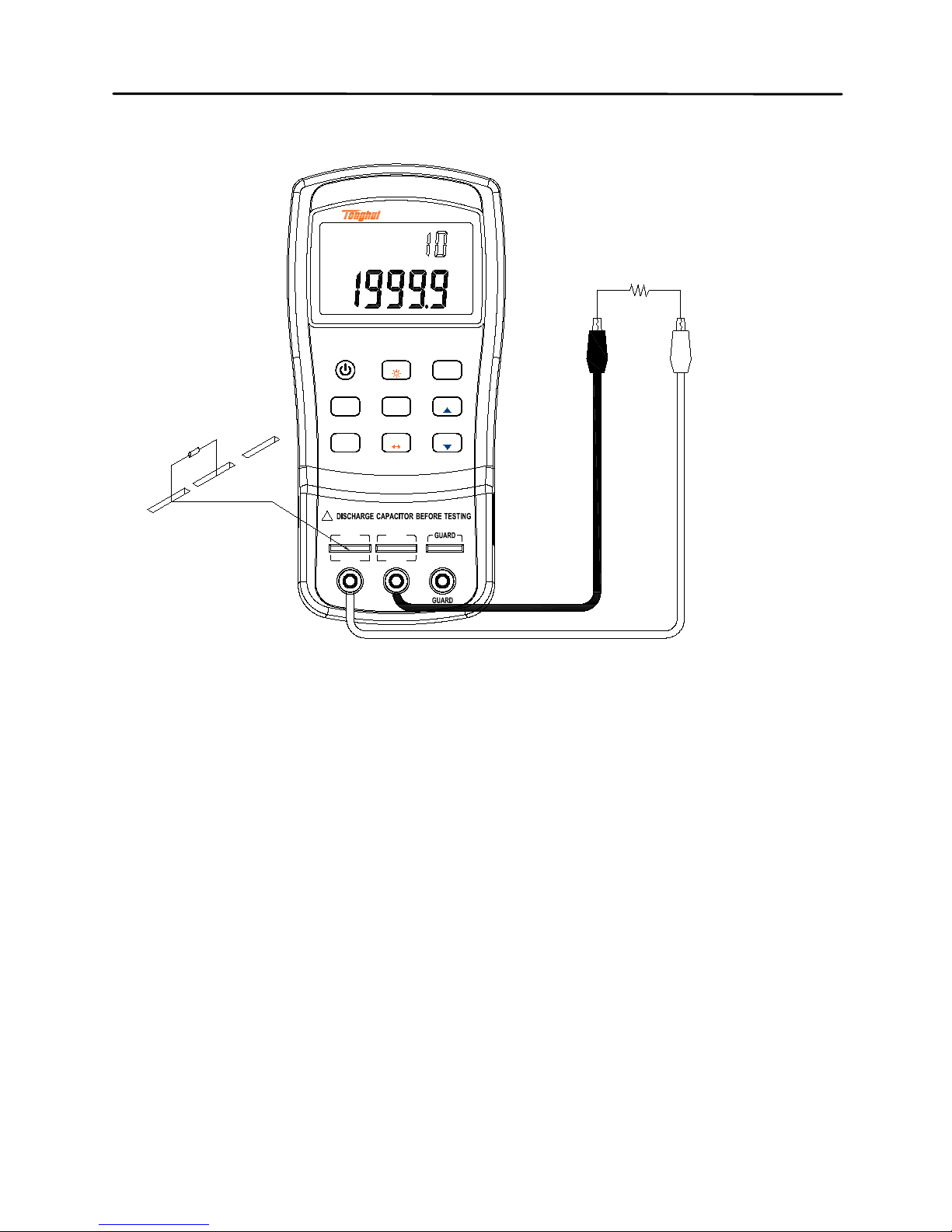
3. Insert a res istor into test sl ots or connect a tes ted
resistor through a proper test accessory (e.g.,
banana plug-crocodile clip test leads, test fixture
or SMD test tweezers). See figure 15. And figure
14 shows the opt ion al 4-terminal test accessories.
4. Press FREQ button until the desired test
frequency is displayed on screen.
5. Press the D/Q/θ/ESR button to select the desired
secondary parameter.
6. Read the readings on LCD for resistance
measured values.
NOTE: The meter uses an AC signal for
measurement of resistance, so what the test result
shows is AC resistance property instead of DC
resistance property.
Page 66
65
+ -
!
H
CUR
L
CUR
H
POT
L
POT
Handheld LCR Meter
100Hz - 100kHz
R
AUTO
D
kHz
PAL
HOLD
FREQ
L/C/R/Z
/ESR
UTIL
CLEAR
RMT
P
S
TOL
RATE
AUTO
REC
D/Q/
TH2822C
@
OFF
θ
Ω
Figure 15- Resistance Measurement
Page 67

66
Impedance Measurement
1. Press the POWER button for a long time to turn
on the instrument.
2. Press the L/C/R/Z button until “Z” is displayed on
the screen to select impedance measurement.
3. Insert impedance (resistor, capacitor or inductor)
into test slots or connect tested impedance
through a proper test accessory (i.e., banana
plug-crocodile clip test leads, test fixture or SMD
test tweezers). Figure 13 shows the optional 4terminal test accessories.
4. Press the FREQ button until the desired test
frequency is displayed on screen.
5. Press the D/Q/θ/ESR button to select the desired
secondary parameter.
6. Read the readings on LCD for impedance
measured values.
Page 68

67
Remote Communication
The meter has the capability to communicate with a
PC over the mini USB interface. Upon installation of a
USB driver, PC can control the instrument and collect
test results over virtual serial interface.
Connecting Instrument to PC
Follow the below procedures for connection setup.
1. Install USB driver from CD or download the USB
driver from www.tonghui.com.cn.
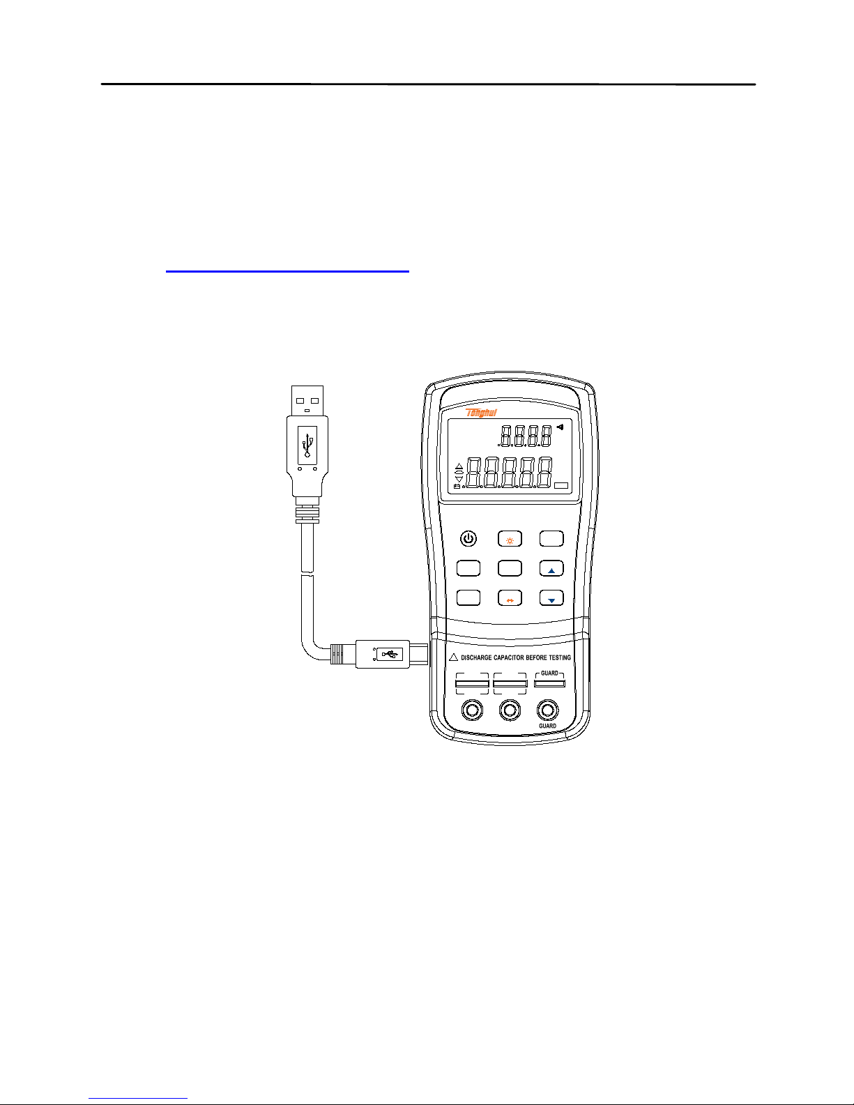
2. With a Mini-USB cable, connect one end of it to
the LCR meter and the other end to an available
USB port on PC. Press the POWER button to turn
on the meter.
3. Skip the next process when the driver has been
stalled.
4. When Windows recognize the USB connection,
PC will prompt user to install driver. The following
process is to cancel installation guide and directly
run the setup program in the setup file.
5. When completed, Windows will create a virtual
serial port and distri bute a serial number. See
Windows device manager for details.
Page 69
68
6. Open the control software and use the assigned
serial number to communicate with the handheld
LCR meter. You can Download the FastAccess
PC communication software from our web site
(
www.tonghui.com.cn) for a demo use.
+ -
!
H
CUR
L
CUR
H
POT
L
POT
Handheld LCR Meter
100Hz - 100kHz
LCR
ESR
MAXAVGMIN
θQ
AUTO
D
2105%
deg
kHz
PAL
SER
μ
H
p
F
μ
RMT
Mk
TOL
DH
n
n
@
OFF
Z
FASTSLOW
HOLD
FREQ
L/C/R/Z
/ESR
UTIL
CLEAR
RMT
P
S
TOL
RATE
AUTO
REC
D/Q/
TH2822C
θ
%
Ω
Ω
Figure 16- Connection to PC
Virtual Serial Port Configuration
Below is the serial communication configuration of
TH2822 series:
Page 70

69
• Baudrate:9600
• Data bits: 8
• Parity: None
• Stop bits: 1
• Flow Control: None
Upon the installati on of USB driver, if the default
assigned by serial port does not match to above
configuration, please modify it as the following
process:
Open Windows device manager→ Port→ Used Ser ial
Port→ Right Click → Property→ Port Set up
RMT Operation
In the case of communication, the RMT button is
used to change the running modes:
Change to Local Operation in Remote Control Mode;
Change to Auto Fetch state in Local Operation mode;
Disable the Auto Fetch function in Auto Fetch state.
NOTE: Auto Fetch state means to send testing result
automatically without needing the initiative inquiry of
PC.
Page 71

70
Remote Mode
Upon the acceptance of any commands from PC, the
meter will be automatically set into remote mode. In
this mode, the LCD display will show “RMT” indicator.
When this is shown, all front panel button will be
locked and disabled, except for RMT and POWER
buttons. If the meter has been in Auto Fetch mode
before receiving remote control commands, Auto
Fetch mode will be disabled.
That is to say, among panel operation, Auto Fetch and
Remote Control, remote control has the highest
priority.
To exit remote control, press the RMT button. When
the “RMT” indicator disappears on the LCD display,
the meter goes back to local operation.
NOTE: If the local operation is locked, RMT button
will be ineffective as well. See *LLO common
command in Command Reference section for details.
Press RMT button to change to Auto Fetch state,
when it is not in the remote mode. See the description
below.
Auto Fetch
When the meter is out of remote control, it can be
changed to Auto Fetch mode. That is, the meter will
Page 72

71
automatically send data to the interface bus upon
every measurement. Therefore, PC will obtain data by
direct reading with no need to send any commands. It
is quite useful in the recording data simply.
Enable/Disable Auto Fetch
To toggle between enabling and disabling auto
fetching when the meter is out of remote control,
press the RMT button. In Auto Fetch, every flash of
“RMT” means send a measurement result.
NOTE: Auto Fetch can be disabled by remote control.
When a remote command is sent to the meter, Auto
Fetch will be disabled. To re-enable Auto Fetch after
remote command, first press the RMT button to return
panel operation and then enter into Auto Fetch mode
by another press of RMT.
Command Protocols
Overview
TH2822 series support SCPI commands with ASCII
character strings transmitting control commands and
returning query information and data and with a
Page 73

72
specified terminator identifying the termination of a
command line or query data line.
The adoption of SCPI commands brings convenience
for the interaction control of PC on the meter through
programming. Command format is compliance with
specifications and easy for understanding and use.
Common Command
The IEEE 488 standard defines the common
commands for general use in all kinds of instrument.
Common commands usually come with the asterisk
“*” character, and may include parameters. Some
examples of Common command like: *IDN?, *GTL,
*LLO. TH2822 series support a few common
commands. See the following command descriptions
for more details.
Termination Character
A terminator is a character sent by a host, which
identifies the end of a command line. Only when a
termination character is received, the instrument will
analyze and deal with command character string.
Terminators can be any one of the following character
strings:
Page 74

73
<CR> (Carriage Return, ASC(&H0D)) ;
<LF> (Line Feed, ASC(&H0A));
<CR><LF>
Returned Result
After the meter executes a query command, the return
of the result will be in the following format:
<Result> + <CR> <LF>
CR is Carriage Return and LF is Line Feed.
For example, in inquiring measured results (FETCH?),
the format of the printed data will be shown as the
following:
<Primary measured data, Secondary
measured data, Tolerance Result> <CR> <LF>
Data Types
Table 4 below explains the different data types
transm itted on bus with ASCII char acter s :
Page 75

74
Table 4 - Data Type
Data Type
Explanation
Example
<NR1>
Integer
+800,-200,100,-50
<NR2>
Real
+1.56,-0.001,10.5
<NR3>
This representation
has an explicit
radix point and an
exponent
+2.345678E+04
-1.345678E-01
<Boolean>
A parameter for
Boolean setting.
Always return “0”
or “1” for Boolean
query command
ON or OFF
<Literal>
A string is used as
command
parameters with
short literal form
HOLD
Symbol Convention
Syntax Symbols in Commands
Below symbols is a part of commands:
Page 76
75
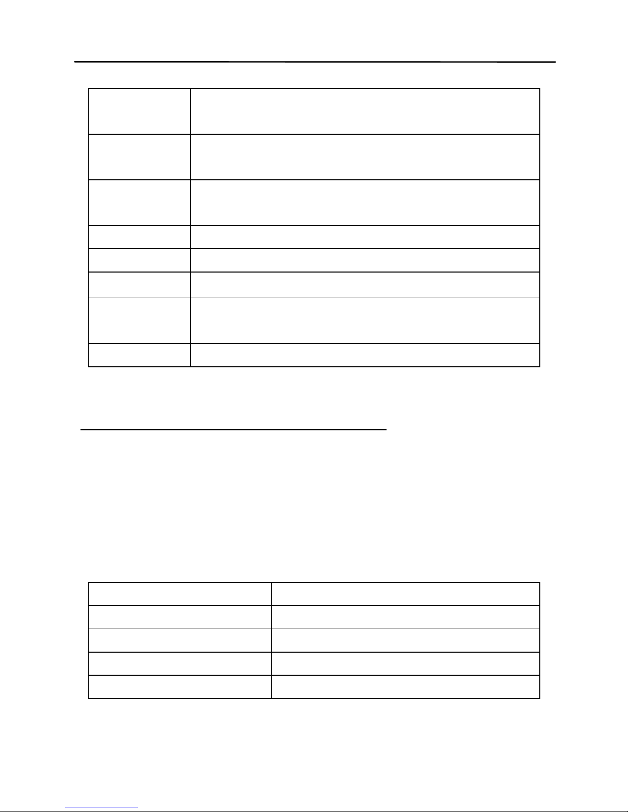
Syntax
Symbol
Explanation
:
Colon means to enter into next
command level
;
Separate another command at the
same command level
*
common command
,
multi-parameter delimiter
?
inquiry
Space, separate commands from
parameters
“ ”
quoting part
Symbols in Command Explanations
Below symbols are used for the description of
command format, which are not the constituting part
of command.
Table 5-Command Specifier
Mark Symbol
Explanation
[ ]
Option; can be om itted
|
Exclusive OR
< >
Defined elem ent
( )
Comment
Page 77

76
Abbreviation, upper case and lower case commands
1. There are two command formats: complete
format and abbreviated format. In the following
command description, capital s ect ion of the
complete commands shows abbreviations
format. It has the same effect of sending
abbreviated and complete commands.
2. Abbreviation command is generally shown in
the form of 4-letter. Any abbreviation absent
from command table is taken as incorrect
command.
3. Either uppercase or lowercase letters, the
effects on the bus are the same.
Page 78

77
Command Reference
Common Command
*IDN?
Query instrument ID.
Return: <instrument model>, <firmware version >,
<serial number>
*LLO
Local Lockout. This means that all front panel buttons,
including the RMT key is not avail able. ( POWER
button is enabled.)
*GTL
Go to local and remove local lockout. If *LLO is sent,
the only way to operate front panel is to go to *GTL.
*TRG
Trigger the instrument to take a measurement. Due to
the automatically continuous test, *TRG command is
of no use.
Page 79
78
SCPI Commands
FREQuency Subsystem
FREQuency <value>
Description: Set measurement frequency
Parameters are 100, 120, 1000, 10000,100000
or 100hz,120hz,1khz,10khz,100khz (model
supported)
Example: FREQuency 100hz
Set 100Hz frequency
FREQuency?
Description: Query the measurement frequency
Return: < 100hz,120hz, 1khz, 10khz,100khz>
FUNCtion subsystem
FUNCtion:impa < L | C | R | Z >
Description: Se lec t primary param eter
Example: FUNCtion:impa L
Selects L as primary parameter
FUNCtion:impa?
Description: Qu ery primar y parameter
Return: <L, C, R, Z, NULL >
FUNCtion:impb < D | Q | THETA | ES R >
Description: Select secondary parameter
Example: FUNCtion:impb D
Select D as secondary parameter
Page 80
79
FUNCtion:impb?
Description: Query secondary parameter
Return: <D, Q, THETA, ESR, NULL>
FUNCtion:EQUivalent < SERies | parallel |
PAL >
Description: Set equ i va lent mode
Parameters: SERies — series mode
Parallel — parallel mode
PAL — parallel mode
Example: FUNCtion:EQUivalent SERies
Set series mode
FUNCtion:EQUivalent?
Description: Query the equivalent mode
Return: <SER, PAL>
CALCulate subsystem
CALCulate:TOLerance:STATe < ON | OFF >
Description: Enable or disable tolerance mode
Example: CALCulate: TOLerance:STATe ON
CALCulate:TOLerance:STATe?
Description: Query the tolerance mode
Return: <ON, OFF >
CALCulate:TOLerance:NOMinal?
Description: Query the nominal value
Return: NR3 or -----(exceeding data range)
Page 81
80
CALCulate:TOLerance:VALUe?
Description: Qu ery the percentage value of
tolerance
Return: NR3 or ----- (exceeding data range)
CALCulate:TOLerance:RANGe < 1 | 5 | 10 |
20 >
Description: Set tolerance range as 1%,5%,10%
or 20% (20% not available for some models )
Example: CALCulate:TOLerance:RANGe 1
Set 1% tolerance range
CALCulate:TOLerance:RANGe?
Description: Query the tolerance range
Return: <BIN1, BIN2, BIN3, BIN4 or ---- >
“----” means unsetting range
CALCulate:RECording:STATe < ON | OFF >
Description: Enable or disable recording function
Example: CALCulate:RECording:STATe ON
CALCulate:RECording:STATe?
Description: Query the recording state
Return: <ON or OFF>
CALCulate:RECording:MAXimum?
Description: Query the maximum value of
recording function
Return: <NR3, NR3> ( primary and secondary
parameters, when data exceeds limits or
there is no data, what returns is“----”.)
Page 82
81
CALCulate:RECording:MINimum?
Description: Query the minimum value of
recording function
Return: <NR3, NR3> (primary and secondary
parameters, when data exceeds limits or
there is no data, what returns is “----“)
CALCulate:RECording:AVERage?
Description: Query the average value of
recording function
Return: <NR3, NR3> (primary and secondary
parameters, when data exceeds limits or
there is no data, what returns is “----“)
CALCulate:RECording:PRESent?
Description: Query the present value of
recording function
Return: <NR3, NR3> (primary and secondary
parameters, when data exceeds limits or
there is no data, what returns is “----“)
FETCh Subsyste m
FETCh?
Description: query the measurement result.
Return: <NR3, NR3, N R1 > that is primary
parameter, secondary parameter and compared
result.
Example: FETCh?
Page 83
82
Summary of Supported SCPI Commands
Table 2 - Summary of SCPI Commands
Command
Parameter
Explanation
FREQuency
<Value>
Set Test Frequency
FREQuency?
Query Test Frequency
FUNCtion
:impa
<Literal>
Select primary display
parameter
:impa?
Query primary display
parameter
:impb
<Literal>
Select secondary display
parameter
:impb?
Query secondary display
parameter
:EQUivalent
<Literal>
Set equivalent mode
:EQUivalent? Query equivalent mode
CALCulate
:TOLerance
:STATe <Boolean> Enable/disable tolerance
mode
:STATe? Query tolerance mode
:NOMinal?
Query nominal value
:VALUe?
Query percent of tolerance
:RANG <Value> Set tolerance range
:RANGe?
Query tolerance range
:RECording
:STATe
<Boolean>
Enable/disable recordi ng
function
:STATe? Query recording state
:MAXimum?
Query max. value of
recording
Page 84
83
:MINimum?
Query min. value of recording
:AVERage?
Query average value of
recording
:PRESent?
Query present value of
recording
FETCh?
Query measurement result
Error Codes
If the received commands or parameters from bus
contain errors, the meter will terminate the analysis
and execution commands. At the same time, error
code will be d ispla yed on L CD and bee p will be sou nd.
Below defines the error description based on the error
code.
E10: Unknown command
E11: Parameter Error
E12: Syntax Error
Page 85
84
Specifications
Below is the general specification and the accuracy
specification of TH2822 series and applicable to
TH2822, TH2822A, TH2822C.
Declaration: The specifications are subject to change
without notice.
*NOTE: 120Hz is the rated frequency. The actual
frequency is 120.048Hz.
General Specifications
Function
Measurement Parameters
Primary: L/C/R/Z
Secondary: D/Q/θ/ESR
Equivalent Mode Series, Parallel
Auto LCR Function Manual, Auto
Ranging Mode Auto
Test Terminals 3-terminal,5-terminal
Measurement Speed 4 meas/sec,1.5meas/sec
Correction Short, Open
Tolerance Mode TH2822 1%,5% , 10%
Page 86
85
TH2822A/C 1%,5% , 10% , 20%
Input Protection Fuse 0.1A / 63V
Interface Mini-USB (virtual serial port)
Test Signal
Signal
Frequency
TH2822 100Hz,*120Hz,1kHz
TH2822A 100Hz,*120Hz,1kHz,10kHz
TH2822C
100Hz,*120Hz,1kHz,10kHz,
100kHz
Test Signal Level 0.6Vrms
Output Impedance 100Ω
Display
Display LCD primary-secondary dual display
Backlight
(not available for
TH2822)
Battery supply: when backlight is on,
luminance is reduced by half 15s later
and automatically turned off 30s later.
Powered by adapter: backlight off until
manually turned off
Readings
Max. Counts of Primary Parameter:
40,000; D / Q / θ Min. resolution of
secondary parameter: 0.0001.
Basic Accuracy
0.25%
(see accuracy specifications for
details)
Primary Range and
Resolution
See Accuracy Specifications
Secondary Range for Displ ay Resolution
Page 87
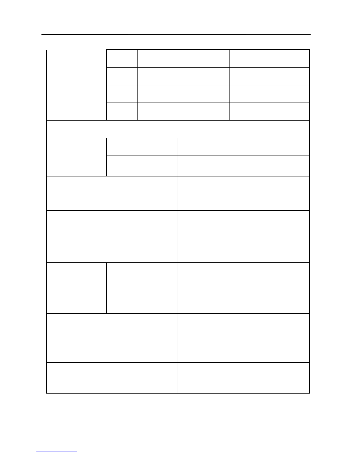
86
Parameter
ESR 0.0000W -- 999.9W 0.0001W
D 0.0000 -- 9.999 0.0001
Q 0.0000 -- 9999 0.0001
θ -179.9° -- 179.9° 0.01°
Power Supply
Battery
Model
TH2822/A IEC 6LR61,9V Alkaline battery
TH2822C
LH-200H7C,8.4V Ni-MH
200mAH rechargeable battery
AC Adapter
Input:220V(1±10% ), 50Hz(1
±5%)
Output:12V -15V DC
Operating Current
(with backlight off)
Max.:28mA
Typical:25mA
(@1kHz,100Ωload)
Standby(Power Off)Current
Max. :2μA(Non-rechargeable)
Battery Life
TH2822/A
16 Hours (typical) based on
backlight off and new alkaline
TH2822C
6 Hours (typical) based on
backlight off and new fully
charged Ni-MH battery
Charge Time and
Current(TH2822C)
Max.: 80min
Max. Current: 42mA
Auto Power Off
(valid for battery powered)
5min/15min/30min/60min/OFF
available ;factory defa ult :5mi n
Low Voltage Indicator
When battery voltage drops
below 6.8V, Low Voltage
Indicator turns on
Page 88
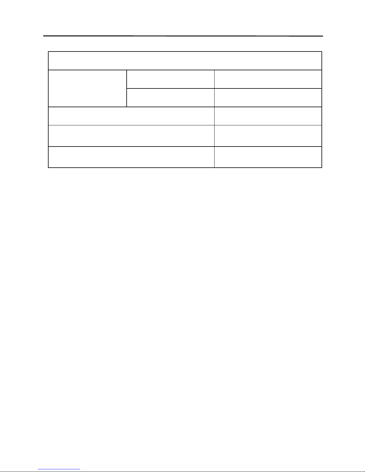
87
General
Operation
Condition
Temperature 0℃ -- 40℃
Relative Humidity ≤90% R.H.
Weight 350g
Dimensions (H ´ W ´ D)
190mm ´ 90mm ´
41mm
Safety and EMC compliance
IEC 61010-1:2001
IEC 61326-2-1:2005
Accuracy Specifications
Notices:
1. Environment temperature:23℃±5℃;
Humidity: ≤75% R.H.
2. Valid after 10 minutes of warm up time.
3. Test in measuring slots on front panel.
4. Measurements performed after correct open
and short correction.
5. Test in the recommended equivalent mode.
6. Percentage accuracy representation:
±(%reading+ least significant digits)
7. Actual measurement and display range may
exceed the ranges in below table, but we do
not specify its accuracy again.
8. Subscript Explanation:
Page 89
88
s—series equivalent; p—parallel equ ival ent;
e—accuracy
9. Some parameters cannot be expressed as
the way of data sheet; therefore they can just
be converted by formulas according to
corresponding results.
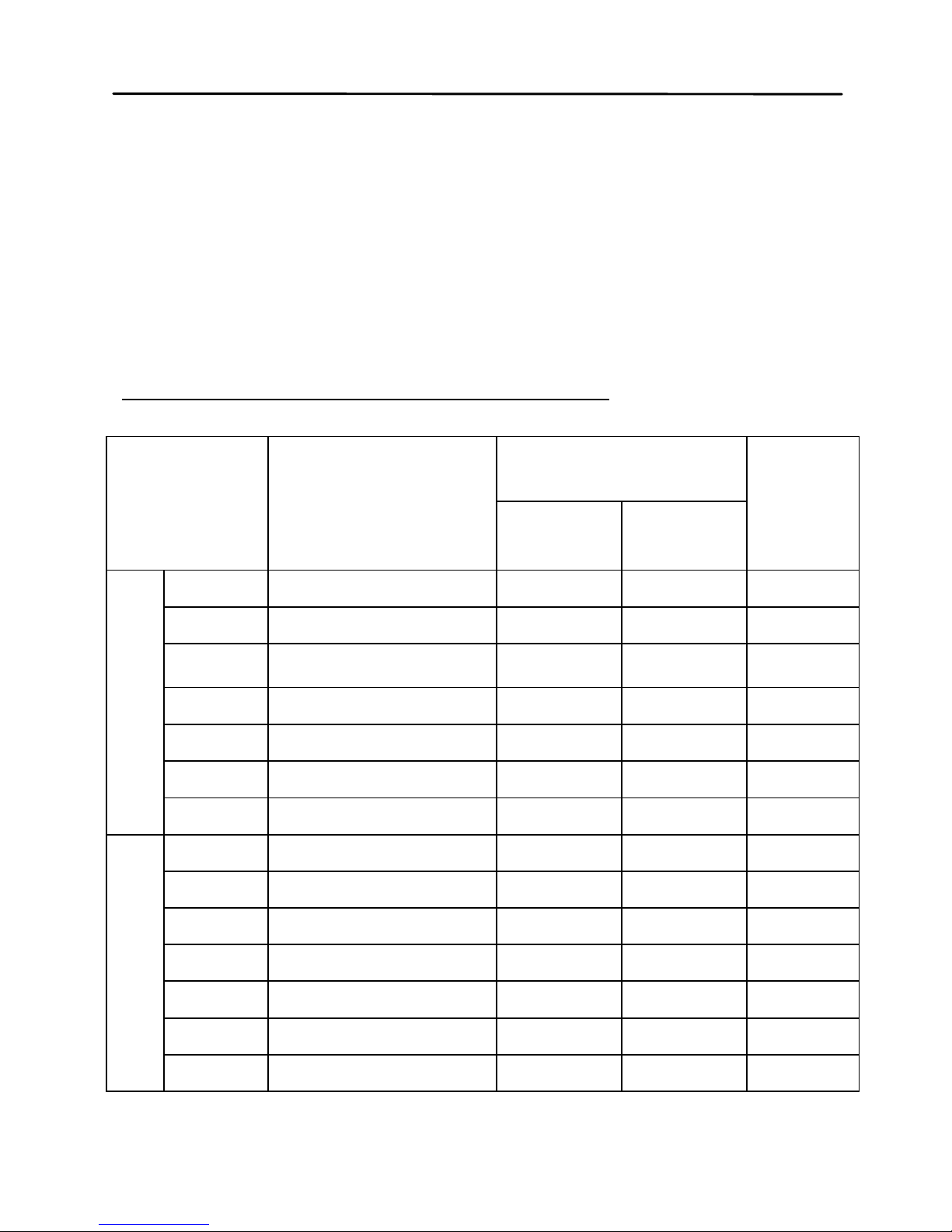
Inductance (L) and Quality Factor (Q)
Range Display Range
Accuracy
Equi-
valent
Mode
Le De *
100Hz/120Hz
1000H 400.0H∼1000.0H 1.00%+3 0.0100 Parallel
400H 40.00H∼399.99H 0.35%+2 0.0035 Parallel
40H 4.000H∼39.999H
0.25%+2 0.0025 Parallel
4H 400.0mH∼3.9999H 0.25%+2 0.0025 ----
400mH 40.00mH∼399.99mH 0.25%+2 0.0025 Series
40mH 4.000mH∼39.999mH 0.45%+2 0.0045 Series
4mH 0uH∼3.999mH 1.40%+5 ------ Series
1kHz
100H 40.00H∼100.00H 1.00%+3 0.0100 Parallel
40H 4.000H∼39.999H 0.35%+2 0.0035 Parallel
4H 400.0mH∼3.9999H 0.25%+2 0.0025 Parallel
400mH 40.00mH∼399.99mH 0.25%+2 0.0025 ----
40mH 4.000mH∼39.999mH 0.25%+2 0.0025 Series
4mH 400.0uH∼3.9999mH 0.45%+2 0.0045 Series
400μH 0.0uH∼399.9μH 1.40%+5 ------ Series
Page 90
89
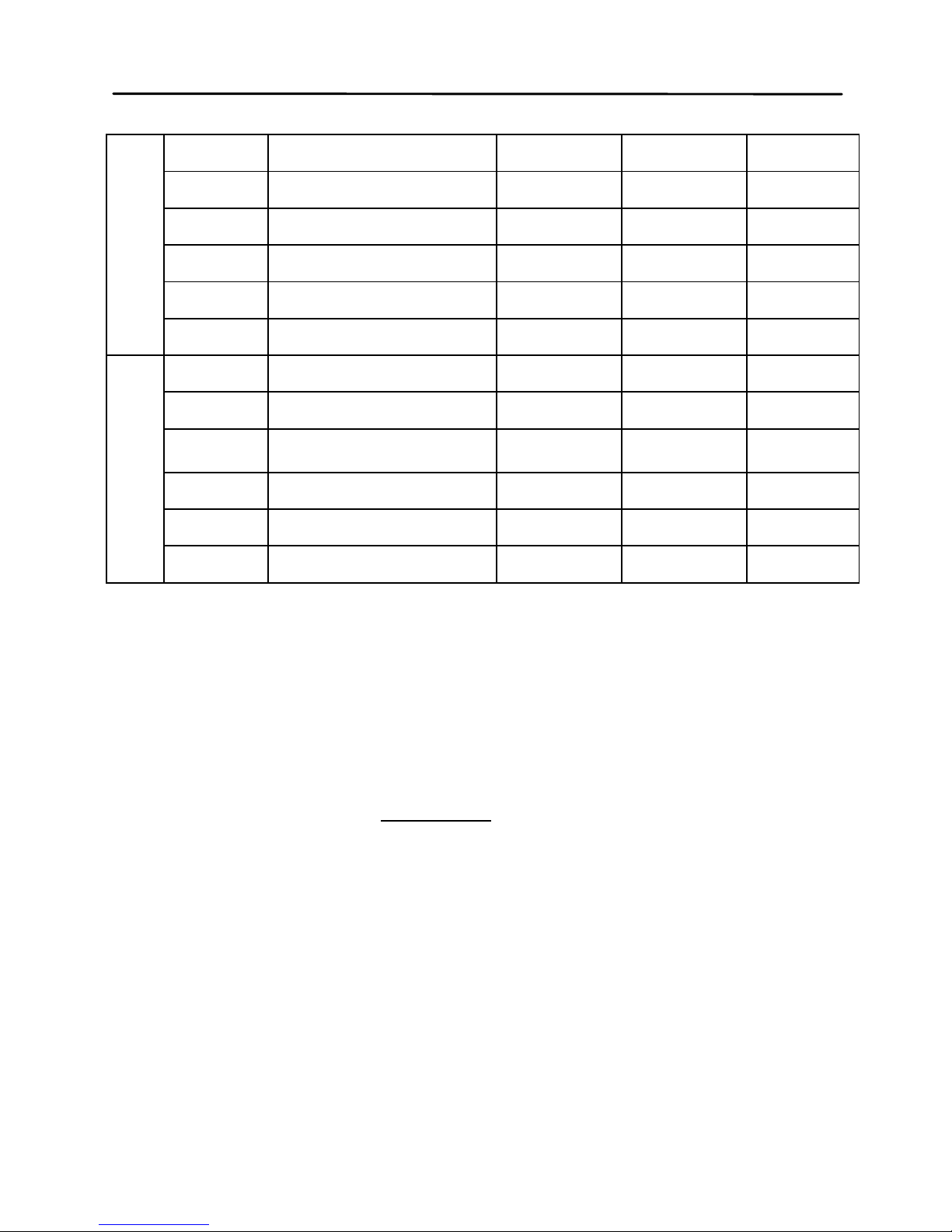
10kHz
1000mH 400.0mH∼999.99mH 0.80%+3 0.0080 Parallel
400mH 40.00mH∼399.99mH 0.35%+2 0.0035 Parallel
40mH 4.000mH∼39.999mH 0.25%+2 0.0025 ----
4mH 400.0uH∼3.9999mH 0.30%+2 0.0030 Series
400μH 40.00uH∼399.99μH 0.45%+2 0.0045 Series
40μH 0.00uH∼39.99μH 1.40%+5 ------ Series
100kHz
100mH 40.00mH∼399.99mH 1.20%+5 0.0120 Parallel
40mH 4.000mH∼39.999mH 0.80%+2 0.0080 Parallel
4mH 400.0uH∼3.9999mH
0.50%+2 0.0050 ----
400μH 40.00uH∼399.99μH 0.50%+2 0.0050 Series
40μH 4.000uH∼39.999μH 0.80%+5 0.0080 Series
4μH 0.000uH∼3.999μH 2.50%+10 ------ Series
*Note: Accuracy of De is assessed when De <0.5
Quality factor Q and Accuracy Qe is calculated by the
following formula:
when
ex
DQ ×
≤ 1,
ex
ex
e
DQ
DQ
Q
×
×
±=
1
2
Where,
x
Q
is the measurement value.
Page 91
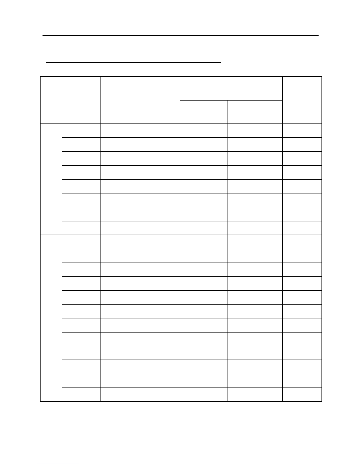
90
Capacitance(C) and Dissipation (D)
Range
Display Range
Accuracy
Equi-
valent
Mode
Ce De*
100Hz/120Hz
20mF 4.000mF∼20.000mF 5.00%+5 ±0.0500 Series
4mF 400.0μF∼3.9999mF 1.00%+3 ±0.0100 Series
400μF 40.00μF∼399.99μF 0.35%+2 ±0.0035 Series
40μF 4.000μF∼39.999μF 0.25%+2 ±0.0025 Series
4μF 400.0nF∼3.9999μF 0.25%+2 ±0.0025 ----
400nF 40.00nF∼399.99nF 0.25%+2 ±0.0025 Parallel
40nF 4.000nF∼39.999nF 0.35%+3 ±0.0035 Parallel
4nF 0pF∼3.999nF 1.25%+5 ------ Parallel
1kHz
1000μF 400.0μF∼999.99μF 2.00%+5 ±0.0200 Series
400μF 40.00μF∼399.99μF 1.00%+3 ±0.0100 Series
40μF 4.000μF∼39.999μF 0.35%+2 ±0.0035 Series
4μF 400.0nF∼3.9999μF 0.25%+2 ±0.0025 Series
400nF 40.00nF∼399.99nF 0.25%+2 ±0.0025 ----
40nF 4.000nF∼39.999nF 0.25%+2 ±0.0025 Parallel
4nF 400.0pF∼3.9999nF 0.35%+3 ±0.0035 Parallel
400pF 0.0pF∼39.99nF 1.25%+5 ------ Parallel
Page 92
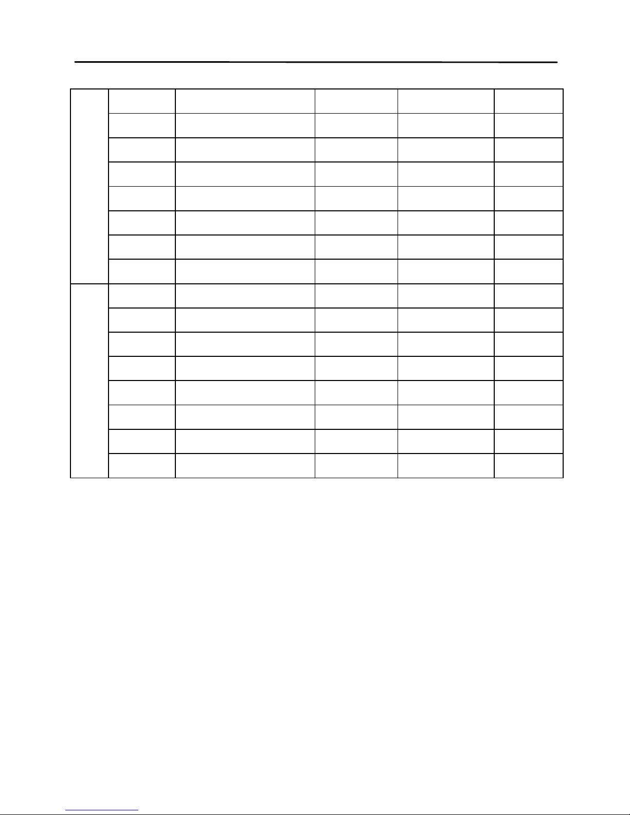
91
10kHz
100μF 40.00μF∼100.00μF 3.00%+5 ±0.0300 Series
40μF 4.000μF∼39.999μF 1.50%+3 ±0.0150 Series
4μF 400.0nF∼3.9999μF 0.35%+2 ±0.0035 Series
400nF 40.00nF∼399.99nF 0.25%+2 ±0.0025 Series
40nF 4.000nF∼39.999nF 0.25%+2 ±0.0025 ----
4nF 400.0pF∼3.9999nF 0.25%+2 ±0.0025 Parallel
400pF 40.00pF∼399.99pF 0.35%+3 ±0.0035 Parallel
40pF 0.00pF∼39.99pF 1.25%+5 ------ Parallel
100kHz
10μF 4.000μF∼10.000μF 6.00%+20 ±0.0600 Series
4μF 400.0nF∼3.9999μF 2.50%+10 ±0.0250 Series
400nF 40.00nF∼399.99nF 0.80%+5 ±0.0080 Series
40nF 4.000nF∼39.999nF 0.50%+2 ±0.0050 Series
4nF 400.0pF∼3.9999nF 0.50%+2 ±0.0050 ----
400pF 40.00pF∼399.99pF 0.80%+2 ±0.0080 Parallel
40pF 4.000pF∼39.999pF 1.20%+5 ±0.0120 Parallel
4pF 0.000pF∼4.999pF 3.00%+10 ------ Parallel
Page 93
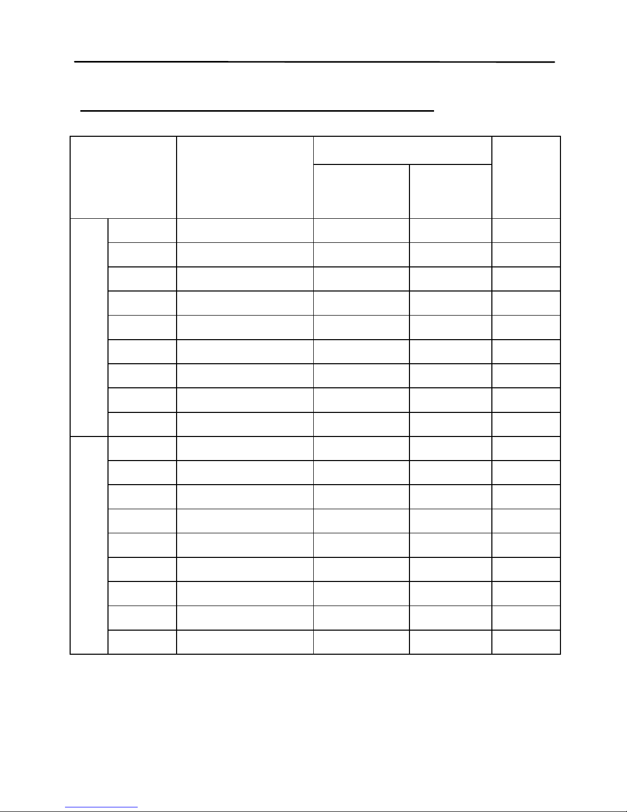
92
Impedance(Z) and Phase Angle
(θ)
Range
Display Range
Accuracy
Equi-
valent
Mode
Ze
θe
100Hz -- 10kHz
10MΩ 4.000MΩ∼10.000MΩ 3.00%+5 ±1.75° Parallel
4MΩ 400.0kΩ∼3.9999MΩ 1.25%+3 ±0.75° Parallel
400kΩ 40.00kΩ∼399.99kΩ 0.35%+2 ±0.25° Parallel
40kΩ 4.000kΩ∼39.999kΩ 0.25%+2 ±0.15° Parallel
4kΩ 400.0Ω∼3.9999kΩ 0.25%+2 ±0.15° ----
400Ω 40.00Ω∼399.99Ω 0.25%+2 ±0.15° Series
40Ω 4.000Ω∼39.999Ω 0.35%+2 ±0.25° Series
4Ω 0.4000Ω∼3.9999Ω 1.00%+3 ±0.60° Series
0.4Ω 0.0000Ω∼0.3999Ω 3.00%+5 ----- Series
100kHz
10MΩ 4.000MΩ∼10.000MΩ 8.00%+20 ±4.60° Parallel
4MΩ 400.0kΩ∼3.9999MΩ 3.00%+10 ±1.75° Parallel
400kΩ 40.00kΩ∼399.99kΩ 1.20%+5 ±0.69° Parallel
40kΩ 4.000kΩ∼39.999kΩ 0.80%+2 ±0.46° Parallel
4kΩ 400.0Ω∼3.9999kΩ 0.50%+2 ±0.30° ----
400Ω 40.00Ω∼399.99Ω 0.50%+2 ±0.30° Series
40Ω 4.000Ω∼39.999Ω 0.80%+5 ±0.46° Series
4Ω 0.4000Ω∼3.9999Ω 2.50%+10 ±1.43° Series
0.4Ω 0.0000Ω∼0.3999Ω 6.00%+20 ----- Series
*Note: Accuracy of De is assessed when De <0.5
Page 94

93
Equivalent Series Resistance
Accuracy of equivalent series resistance is calculated
by below formula:
Rse =
ex
X
φ
×±
Where,
x
X
is measured reactance,
xx
fLX
π
2=
or
x
x
fC
X
π
2
1
=
e
φ
is the phase angle accuracy,
180
π
θφ
×=
ee
Notice:the accuracies of ESR and Rs are same.
Equivalent Para ll el Resis ta nc e
Accuracy of equivalent series resistance is calculated
according to the below formula:
Rpe =
ex
epx
D
R
φ
φ
×
±
R
px
is the measured value of Rp, Dx is the measured
value of dissipation.
Page 95

94
Maintenance
W
ARNING: Do not perform any service by
yourself. Service should only be done by quali fied
personnel and trained technicians.
WARNING: Beware of liquid and residues,
especially conductive matter.
Se
rvice
I
f the instrument fails to power on, first check battery,
external source and power sockets and the validity of
buttons.
If the measurement result is abnormal, first inspect the
condition of test accessories and damage of reed in
test slots. See operation manual for information of
correct operation.
Do not replace components. Contact the after-sale
department of our company or relevant distributors for
uncertain maintenance.
The meter must be turned off or removed from
external power before replacing battery. See Installing
Battery section for details.
Page 96

95
Cleaning
B
efore cleaning this meter, make sure the power is
OFF and remove external AC adapter if one is used.
To avoid electrical shock or damaging the meter,
prevent water from getting inside the case. In the case
that water gets inside, remove the battery immediately
and do not operate the instrument immediately.
To clean the meter, wipe the dirty parts with a soft
cloth soaked with diluted neutral detergent. Avoid
having the instrument too wet to prevent the detergent
from penetrating into the inside components of the
meter, causing damages.
After cleaning, make sure the instrument is completely
dried before operating it again.
Page 97

96
Limited Warranty
The instrument, component parts and accessories will
be free from defects in workmanship and materials for
a period of two years from date of purchase.
Tonghui will, without charge, repair or replace, at its
option, defective product or component parts.
Returned product must be accompanied by proof of
the purchase date in the form of a sales receipt and
the included accessories.
This warrant y does not appl y in the event of mis us e or
abuse of the product or as a result of unauthorized
alterations or repairs.
The warranty is void if the serial number is altered,
defaced or removed.
 Loading...