

Page 1

OPERATION MANUAL
TH2816B
Precision LCR Meter
Page 2

2
Contents
Chapter 1 Overview.......................................................................................................................5
1.1 Product introduction....................................................................................................5
1.2 Operation conditions...................................................................................................6
1.2.1 Power requirements...................................................................................................6
1.2.2 Operation environment..............................................................................................6
1.2.3 Warm-up time............................................................................................................6
1.2.4 Notes for usage..........................................................................................................6
1.3 Dimension and weight...................................................................................................7
1.4 Safety Summary............................................................................................................7
1.5 Electromagnetic compatibility......................................................................................7
Chapter 2 Basic Specifications..................................................................................................8
2.1 Measurement Functions................................................................................................8
2.1.1 Measurement Parameters..........................................................................................8
2.1.2 Combinations of Measurement Parameters...............................................................8
2.1.3 Equivalent Circuit.....................................................................................................8
2.1.4 Ranging.....................................................................................................................9
2.1.5 Trigger.......................................................................................................................9
2.1.6 Delay Time..............................................................................................................10
2.1.7 Measurement Terminals..........................................................................................10
2.1.8 Measurement Speed................................................................................................10
2.1.9 Averaging................................................................................................................10
2.1.10 Basic Accuracy........................................................................................................10
2.2 Test Signal...................................................................................................................10
2.2.1 Test Signal Frequency.............................................................................................10
2.2.2 Test signal level.......................................................................................................10
2.2.3 Output impedance ...................................................................................................11
2.2.4 Test Signal Level Monitor.......................................................................................11
2.2.5 Display Range.........................................................................................................11
2.3 Functions.....................................................................................................................11
2.3.1 Correction Functions...............................................................................................11
2.3.2 Comparator function ...............................................................................................11
2.3.3 Measurement results display...................................................................................12
2.3.4 File Function ...........................................................................................................12
2.3.5 Other Function ........................................................................................................12
2.3.6.1 Ranging mode.........................................................................................................12
2.3.6.2 Contrast adjustment.................................................................................................12
2.3.6.3 Beep ........................................................................................................................12
2.3.6.4 Comparator alarm....................................................................................................12
2.3.6.5 Key lock function....................................................................................................12
2.3.6.6 Password .................................................................................................................13
2.3.7 Interface Function ...................................................................................................13
2.3.7.1 IEEE488 interface...................................................................................................13
2.3.7.2 RS232C interface....................................................................................................13
2.3.7.3 HANDLER interface...............................................................................................13
Chapter 3 Panel and Display Introduction ......................................................................................14
3.1 A Tour of the Front Panel............................................................................................14
3.2 A Tour of the Rear Panel.............................................................................................15
3.3 Display Area Definition..............................................................................................16
3.4 MENU keys and Display Page....................................................................................16
3.5 Summary of Pages.......................................................................................................17
Chapter 4 Operation.....................................................................................................................19
4.1 Basic operation............................................................................................................19
4.2 Welcome Page.............................................................................................................20
4.3 Detailed Operation......................................................................................................21
4.3.1 MeasDisplay Page...................................................................................................21
4.3.1.1 Measurement Function............................................................................................22
Page 3

3
4.3.1.2 Test Frequency ........................................................................................................23
4.3.1.3 Oscillator Level.......................................................................................................24
4.3.1.4 Measurement Range................................................................................................25
4.3.1.5 Measurement Speed................................................................................................26
4.3.1.6 Short Correction......................................................................................................26
4.3.1.7 Open Correction......................................................................................................27
4.3.1.8 File Management.....................................................................................................27
4.3.1.9 Useful Tools ............................................................................................................29
4.3.2 Bin Number Display Page.......................................................................................30
4.3.2.1 Comparator Function ON/OFF...............................................................................31
4.3.2.2 Auxiliary Bin ON/OFF ...........................................................................................31
4.3.2.3 File Management.....................................................................................................32
4.3.2.4 Useful Tools ............................................................................................................32
4.3.3 Meas Setup Page.....................................................................................................33
4.3.3.1 Trigger Mode...........................................................................................................35
4.3.3.2 Output Signal impedance........................................................................................36
4.3.3.3 Delay Time (DELAY )............................................................................................36
4.3.3.4 Averaging Rate (AVG)............................................................................................36
4.3.3.5 Signal Level Monitor ON/OFF...............................................................................36
4.3.3.6 Deviation Measurement Function...........................................................................37
4.3.3.7 File Management.....................................................................................................38
4.3.3.8 Useful Tools............................................................................................................38
4.3.4 Limit Table ..............................................................................................................38
4.3.4.1 Nominal Value for tolerance mode..........................................................................39
4.3.4.2 Swap Parameter Function........................................................................................40
4.3.4.3 Comparator Function's Limit Mode........................................................................40
4.3.4.4 Comparator Function ON/OFF...............................................................................40
4.3.4.5 Auxiliary bin ON/OFF............................................................................................40
4.3.4.6 Low/High Limit Value ............................................................................................40
4.3.4.7 File Management (File)...........................................................................................41
4.3.4.8 Useful Tools............................................................................................................41
4.3.5 System Configuration Page .....................................................................................41
4.3.5.1 LCD Contrast Function...........................................................................................42
4.3.5.2 Information Beeper Function ON/OFF...................................................................43
4.3.5.3 Comparator Alarm Function ON/OFF ....................................................................43
4.3.5.4 Password Function..................................................................................................43
4.3.5.5 Bus Mode Function.................................................................................................44
4.3.5.6 GPIB address...........................................................................................................44
4.3.5.7 AutoFetch mode ON/OFF.......................................................................................44
Chapter 5 Remote Control ..............................................................................................................45
5.1 RS232C Interface Introduction ...................................................................................45
5.1.1 RS232C Connection................................................................................................45
5.1.2 Communication with a Computer...........................................................................46
5.1.3 Communication with a DC Bias Current Source....................................................49
5.2 GPIB Interface Introduction........................................................................................50
5.2.1 GPIB Connection....................................................................................................50
5.2.2 GPIB Interface Capabilities Functions....................................................................53
5.2.3 GPIB Addressing.....................................................................................................53
5.2.4 GPIB Bus Function.................................................................................................53
5.3 Data Format.................................................................................................................53
5.3.1 Format 1..................................................................................................................54
5.3.2 Format 2..................................................................................................................55
Chapter 6 Command Reference......................................................................................................56
6.1 Notation Conventions and Definitions........................................................................56
6.2 Command Structure.....................................................................................................56
6.3 Command Abbreviations.............................................................................................58
6.4 Suffix Units and suffix Multipliers .............................................................................58
Page 4

4
6.5 Command Reference...................................................................................................59
6.5.1 DISPlay Subsystem.................................................................................................60
6.5.2 FREQuency Subsystem...........................................................................................61
6.5.3 VOLTage Subsystem...............................................................................................62
6.5.4 FUNCtion Subsystem..............................................................................................63
6.5.5 APERture Subsystem..............................................................................................66
6.5.6 TRIGger Subsystem................................................................................................67
6.5.7 FETCh? Subsystem.................................................................................................68
6.5.8 ABORt Subsystem..................................................................................................69
6.5.9 CORRection Subsystem..........................................................................................69
6.5.10 COMParator Subsystem..........................................................................................71
6.5.11 Mass MEMory Subsystem......................................................................................76
6.5.12 Common Commands...............................................................................................77
6.5.13 Error and Warning Messages...................................................................................78
Chapter 7 Handler Interface.........................................................................................................79
7.1 Basic Information........................................................................................................79
7.2 Handler Interface Operation........................................................................................79
7.2.1 Signal line definition...............................................................................................79
7.2.1.1 Signal Line Used for Comparator Function............................................................79
7.2.1.2 Signal Line Used for List Sweep Comparator Function.........................................83
7.3 Electrical Characteristics.............................................................................................87
7.3.1 DC Isolated Outputs................................................................................................ 87
7.3.2 DC Isolated Input....................................................................................................89
7.4 Setting Up the Handler Interface Board ......................................................................89
7.5 Operation.....................................................................................................................91
7.5.1 Setting Procedure For Comparator Function...........................................................91
7.5.2 Setting Procedure For List Sweep Comparator function.........................................91
Page 5

5
Chapter 1 Overview
Thank you for choosing our product. The contents of the shipment should be as listed in
the packing list. If the contents are incomplete, if there is mechanical damage or defect, or
if the instrument does not pass the power-on self tests, please notify our company.
1.1 Product introduction
TH2816B is a precision LCR meter with high accuracy, good stability, and wide
measurement range. Controlled by a 16 bits MPU, TH2816B can be used for
evaluating LCR components, materials and semiconductor devices over a wide range
of frequencies (50 Hz to 200 kHz) and test signal levels (0.01 V to 2.00 V, with 0.01 V
resolution ). With its powerful function, excellent performance, perspicuous LCD
display and easy menu operation, TH2816B is suitable for high speed measurement
need on product line and high accuracy and stability measurement need in laboratory.
By using the Handler interface, IEEE488 interface (optional), and RS232C interface,
TH2816B can easily be used for automatic test system and computer remote control.
The instrument provides variable test conditions, typical conditions are as follows:
z Test signal frequency
37 typical frequency points available from 50 Hz to 200 kHz.
z Test signal level
Programmable signal level from 0.01 V to 2.00 V in 0.01 V resolution.
z Measurement speed
Fast, Medium and Slow measurement speed can be selected. Using the
averaging rate (from 1 to 255 programmable) function, you can get more stable
measurement results.
z Constant signal source output impedance
30 Ω or 100Ω selectable
z Bias current
TH2816B can control the external bias current source (for example TH1773) for
bias current list sweep measurement.
z Correction function
The OPEN, SHORT correction for correcting the stray admittance, the residual
impedance, and the other errors can be performed. The correction function has
two kinds of correction methods. In one method the open and short correction
can be performed at all of the frequency points, and in the other method the open,
short correction can be performed at the frequency points you specify.
z Test signal level monitor
The actual signal level may be different with the setup signal level. The level
monitor function allows you to monitor the actual voltage level across the device
under test or the actual current level though the device under test.
TH2816B provides 3 types of display results and 2 kinds of comparison methods
z Direct readout: The actual measurement results are displayed.
Absolute deviation (ΔABS): The difference between the measured value of
the DUT and a previously stored reference value
are displayed.
Percent deviation (Δ%): The difference between the measured value of the
DUT and a previously stored reference value are
displayed as a percentage of the reference value.
Page 6

6
z Absolute deviation or percent deviation can be set as comparison limits.
TH2816B can output comparison results for sorting components into a maximum
of 10 bins. (BIN1 to BIN 9 and OUT). Also, devices whose primary parameter is
within limits, but whose secondary parameter measurement result is not within
limits, can be sorted into an AUXiliary BIN.
TH2816B provides several communication interfaces which make it easy to output
the measurement results to other equipments (for example computers), or build an
automatic test system.
z RS232C interface: RS232C interface make it easy to communicate with other
equipments. You can set the measurement functions and input the parameters
through the RS232C interface instead of front panel keyboard.
The RS232C interface can also be used as the control interface for the external
bias current source.
z IEEE488 interface (optional): The IEEE488 interface is an optional interface on
the TH2816B and can be used to build an automatic test system to completely
characterize new components and materials, and to fully automate production
line testing.
z HANDLER interface(optional): By using the handler interface, the TH2816B can
easily be combined with a component handler, and a system controller to fully
automate component testing, sorting, and quality control data processing.
TH2816B’s file function can save the setup parameters, limit parameters and list
sweep parameters as a file in the internal nonvolatile memory, and the No. 0 file will
be automatically reloaded when TH2816B is powered on.
1.2 Operation conditions
1.2.1 Power requirements
TH2816B requires the following power source:
Voltage: 198 to 242 Vac
Frequency: 47 to 66 Hz
Power: 50 VA maximum
1.2.2 Operation environment
TH2816B must be operated under within the following environment conditions.
Temperature:0℃ to 40℃
Humidity: less then 90% RH
1.2.3 Warm-up time
Allow TH2816B to warm up a minimum of 20 minutes before starting tests.
1.2.4 Notes for usage
z Please do not operate the instrument in the places where is vibrative, dusty,
under direct sunlight, or where there is corrosive air.
z Although the instrument has been specially designed for reducing the noise
cased by ac power, a place with low noise is still recommended. If this cannot be
arranged, please make sure to use power filter for the instrument.
z Please store the instrument in the place where temperature is between 5℃ and
40℃, humidity is less then 85% RH. If the instrument will not be put in use for a
time, please have it properly packed with its original box or a similar box for
storing.
z TH2816B has the cooling fan on the rear panel and cooling holes on both sides.
High temperature inside will decrease the measurement accuracy, so sufficient
space must be kept around the TH2816B to avoid obstructing the air flow of the
Page 7

7
cooling fans.
z Don’t frequently turn on and off the instrument, doing so will lead to the loss of
the calibrated data and the data saved by users.
1.3 Dimension and weight
Dimensions: 350(W) by 110(H) by 340(D) (mm)
Weight: Approximately 4 kg
1.4 Safety Summary
The following general safety precautions must be observed during all phases of
operation, service, and repair of this instrument.
Ground the Instrument
To avoid electric shock hazard, the instrument chassis and cabinet must be
connected to a safety earth ground by the supplied power cable with earth blade.
DO NOT Operate In an Explosive Atmosphere
Do not operate the instrument in the presence of flammable gasses or fumes.
Operation of any electrical instrument in such an environment constitutes a definite
safety hazard.
Keep Away From Live Circuits
Operating personnel must not remove instrument covers. Component replacement
and internal adjustments must be made by quailed maintenance personnel. Do not
replace components with the power cable connected. Under certain conditions,
dangerous voltages may exist even with the power cable removed. To avoid injuries,
always disconnect power and discharge circuits before touching them.
DO NOT Service or Adjust Alone
Do not attempt internal service or adjustment unless another person, capable of
rendering first aid and resuscitation, is present.
DO NOT Substitute Parts or Modify Instrument
Because of the danger of introducing additional hazards, do not install substitute
parts or perform unauthorized modifications to the instrument. Return the instrument
to our Sales and Service Office for service and repair to ensure that safety features
are maintained.
1.5 Electromagnetic compatibility
This product has been designed and tested to the requirements of the
Electromagnetic Compatibility (EMC) Directive. To use a properly shielded cable or
shielded coaxial cable to connect each of the ports to their respective controllers,
peripherals, equipments or devices may ensure to meet the requirements.
Page 8
8
Chapter 2 Basic Specifications
2.1 Measurement Functions
2.1.1 Measurement Parameters
L: Inductance
C: Capacitance
R: Resistance
|Z|: Absolute value of impedance
X: Reactance
B: Susceptance
G: Conductance
D: Dissipation factor
θ: Phase angle
Q: Quality factor
2.1.2 Combinations of Measurement Parameters
Suffix “s” means series; suffix “p” means parallel.
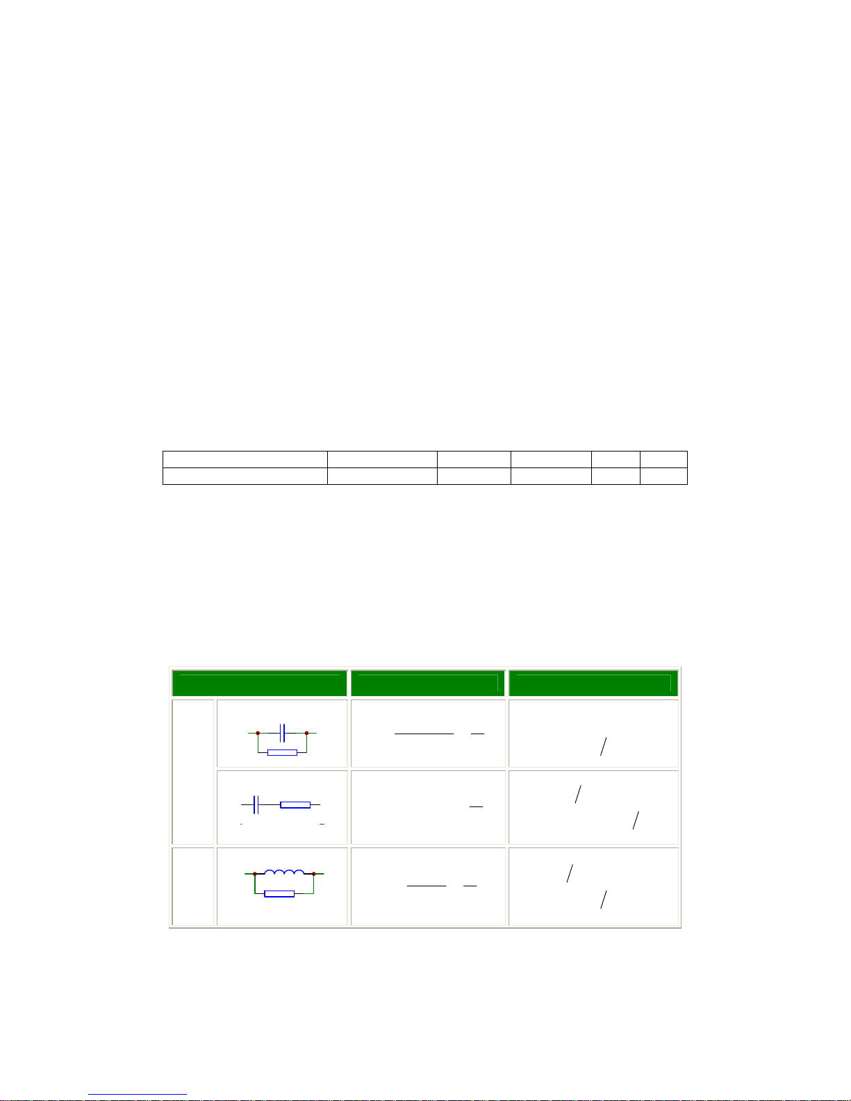
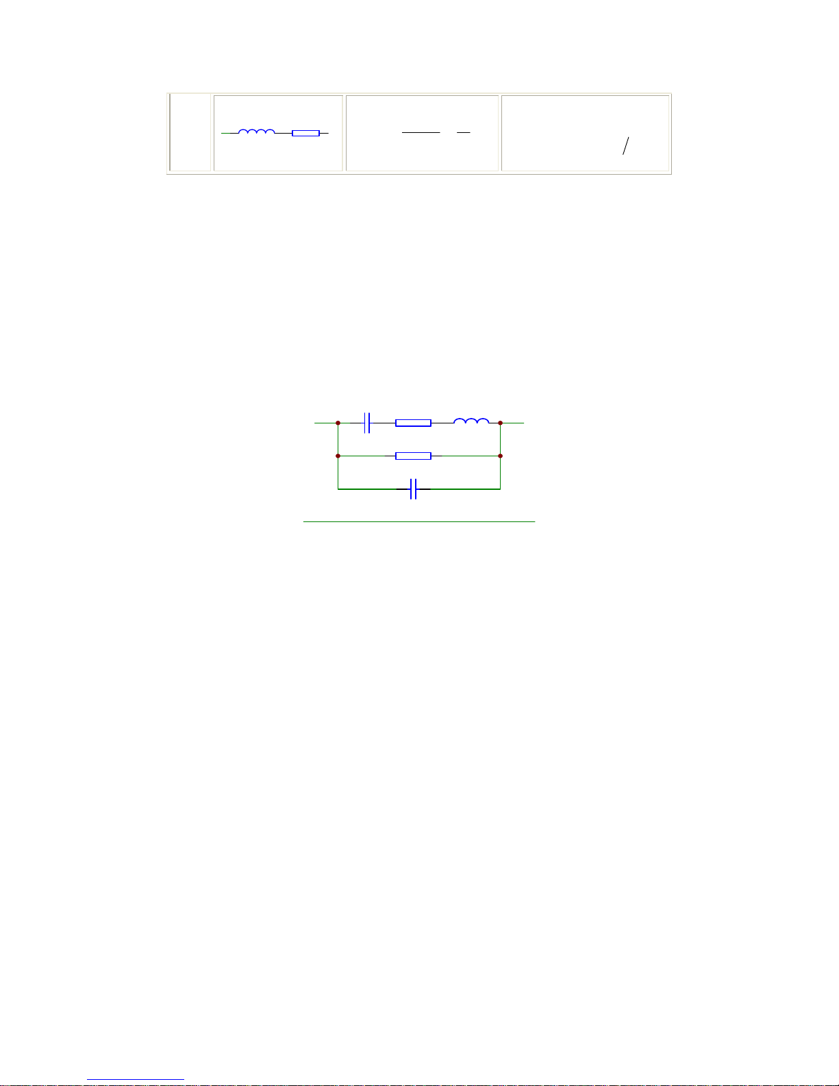
2.1.3 Equivalent Circuit
The actual capacitor, resistor and inductor are not the ideal capacitor, resistor and
inductor. Normally, a component has the characteristics of the resistor and the
reactor at the same time. The actual component is composed of an ideal resistor and
reactor (ideal inductor or capacitor) in series or parallel equivalent circuits.
The values in the two different equivalent circuits can be converted to each other
using the following formulas in Table 2-1. The values are different due to the quality
factor Q (or the dissipation factor D).
Table 2-1 Parallel and Series Circuit Mode
Circuit Mode Dissipation Factor Conversion
Cp
QRfC
D
Pp
1
2
1
==
π
)1(
)1(
22
2
DDRR
CDC
PS
PS
+=
+=
C
Cs
Rs
Q
CfRD
SS
1
2 ==
π
22
2
)1(
)1(1
DDRR
CDC
SP
SP
+=
+=
L
Lp
Rp
QR
fL
D
P
P
1
2
==
π
)1(
)1(1
22
2
DDRR
LDL
PS
PS
+=
+=
Main parameters Z L C R G
Secondary parameters θ(deg), θ(rad) Q,Rs,Rp D, Rs, Rp X B
Page 9
9
Lp Rp
QfL
R
D
S
S
1
2
==
π
22
2
)1(
)1(
DDRR
LDL
SP
SP
+=
+=
L: Inductor C: Capacitor f: Frequency
R: Resistor D: Dissipation factor Q: Quality factor
Suffix s: Series Suffix p: Parallel
The following description gives some practical guidelines for selecting the
capacitance measurement circuit mode.
a) We can select the circuit mode according to the variation of D at two different
frequencies. If the dissipation factor of a capacitor increases with the increase of
the test frequency, series circuit mode should be selected. If the dissipation factor
decreases with the increase of the test frequency, parallel circuit should be used.
For inductor, the situation is just in the opposite side. In fact, D is impossible in
direct ratio with the test frequency. From Figure 2-1, we can find that Rp and Rs
exist at the same time. If Rs is more significant than Rp, series mode is selected;
If Rp is more significant than Rs, parallel mode is more suitable.
Cs
Rp
Cx
Rs Lo
Figure 2-1. Equivalent circuit of an actual capacitor
Where,
Cx: ideal capacitor
Rx: resistance of the leads
Lo: inductance of the leads
Rp: insulation resistance across the capacitor
Co: stray capacitor across the capacitor.
For a given frequency F, Cs and Cp can be calculated.
b) When there is no proper information available, please make decision according to
following rules:
For low impedance component(such as large capacitor or small inductor),
the series equivalent circuit mode should be used.
For high impedance component(such as small capacitor or large inductor),
the parallel equivalent circuit mode is the appropriate choice.
If a capacitor is used as a filter capacitor, series circuit mode is the best
choice.
If a capacitor is used in a LC oscillator then parallel circuit mode can be
selected.
2.1.4 Ranging
Auto and Manual (Hold/Up/Down), total 9 ranges.
2.1.5 Trigger
TH2816B has four trigger modes: INTernal, EXTernal, MANual, and BUS. Except for
BUS trigger mode these trigger modes can be set on the front panel. The BUS trigger
mode is used when TH2816B is controlled via GPIB.
Internal: When the trigger mode is set to INTernal trigger mode, TH2816B
continuously repeats measurements.
Page 10

10
External: When the trigger mode is set to EXTernal, TH2816B performs a single
measurement every time a low-to-high transition TTL level signal is applied
to the Handler interface on the rear panel.
BUS: When the trigger mode is set to BUS trigger mode, TH2816B performs a
single measurement every time the *TRG common command is sent to
TH2816B via GPIB. The BUS trigger mode cannot be set on the front panel.
Send the TRIGger:SOURce BUS command via GPIB or RS232C to set the
trigger mode to the BUS trigger mode.
Manual: When the trigger mode is set to MANual trigger mode, TH2816B performs a
single measurement every time when TRIGGER key on the front panel is
pressed.
2.1.6 Delay Time
Programmable delay from the trigger command to the start of the measurement, 0 to
60.000 s in 1 ms steps.
2.1.7 Measurement Terminals
Four terminals:
HD (H
CUR
): High current
HS (H
POT
): High potential
LS (L
POT
): Low potential
LD (L
CUR
): Low current
2.1.8 Measurement Speed
TH2816B’s measurement speed is determined by Integration time, measurement
result display time, averaging rate and delay time.
FAST: about 25 meas/sec, maximum 30 meas/sec.
MED: about 10 meas/sec.
SLOW: about 1.5 meas/sec.
2.1.9 Averaging
1 to 255, programmable
2.1.10 Basic Accuracy
0.05%
2.2 Test Signal
2.2.1 Test Signal Frequency
Total 37 typical frequency points available from 50Hz to 200kHz:
50Hz、60Hz、80Hz、100Hz、120Hz、150Hz、200Hz、250Hz、300Hz、400Hz、
500Hz、600Hz、800Hz、1kHz、1.2kHz、1.5kHz、2kHz、2.5kHz、3kHz、4kHz、
5kHz、6kHz、8kHz、10kHz、12kHz、15kHz、20kHz、25kHz、30kHz、40kHz、50kHz、
60kHz、80kHz、100kHz、120kHz、150kHz、200kHz
Frequency Accuracy: 0.02%
2.2.2 Test signal level
0.01 V to 2.00 V, 0.01 V resolution
Level accuracy: ±(10%×setup value+2 mV)
Page 11
11
2.2.3 Output impedance
30Ω±5% (default), 100Ω±5%
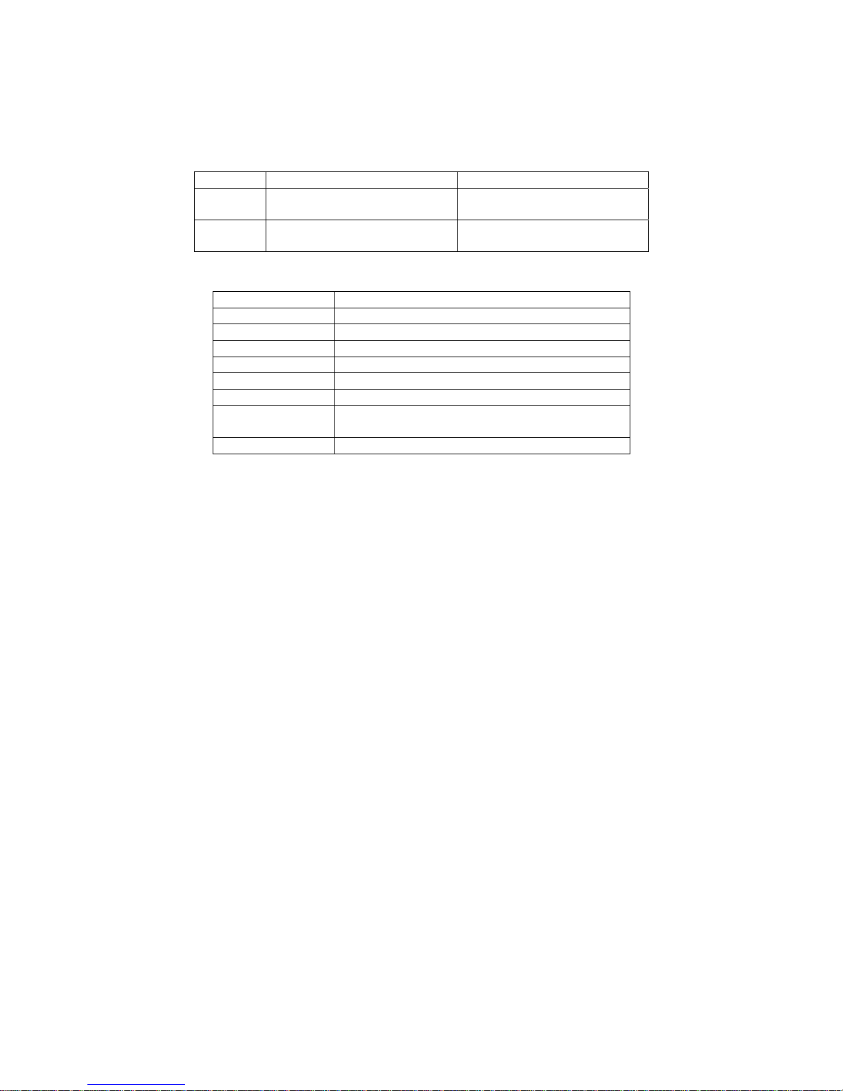
2.2.4 Test Signal Level Monitor
Mode Range Monitor Accuracy
Voltage
10 mV
rms
– 2.00 V
rms
0.01 mV
rms
–10 mV
rms
±(3% of reading+0.5mV)
±(12% of reading+0.1mV)
Current
100μA
rms
– 66mA
rms
0.001μA
rms
– 100 μA
rms
±(3% of reading+5μA)
±(12% of reading+1μA)
2.2.5 Display Range
Parameter Range
L 0.01 nH to 9999.99 H
C 0.00001 pF to 999.999 mF
R, X, Z 0.01 mΩ to 99.9999 MΩ
B, G 0.01 nS to 999.999 S
D 0.00001 to 9.99999
Q 0.01 to 99999.9
θ Deg -179.999° to 179.999°
Rad -3.14159 to 3.14159
% -99.999% to 999.999%
2.3 Functions
2.3.1 Correction Functions
Open correction
Eliminates measurement errors due to parasitic stray admittance (C, G) of the
test fixture. Three frequency points or sweep frequency Open correction is
available.
Short correction
Eliminates measurement errors due to parasitic residual impedances (L, R) of
the test fixture. Three frequency points or sweep frequency Short correction is
available.
Load correction
Improves the measurement accuracy by using a device which value is accurately
known (a working standard) as a reference. Three frequency points load
correction is available.
2.3.2 Comparator function
10-bin sorting for the primary measurement parameter, and IN/ OUT decision output
for the secondary measurement parameter.
BIN1 to BIN9: Both primary and secondary measurement parameters are within
limits.
OUT BIN: Primary parameter is not within limits. Or primary parameter is within
limits, secondary parameter is not within limits, and AUX bin is off.
AUX BIN: Primary parameter is within limits, but whose secondary parameter
measurement result is not within limits.
If the secondary parameter limits are not set, TH2816B will not compare the
secondary parameter.
z Sorting Modes
Absolute deviation mode: absolute deviations are compared with bin limits.
Percent deviation mode: percent deviations are compared with bin limits.
z Bin Count
Each bin has a bin counter, counts from 0 to 999999.
Page 12

12
z Display pages
BinNo. Disp page and Bin Count page
More detail information is outputted through the Handler interface:
PHI: Primary measurement parameter is high.
PLO: Primary measurement parameter is low.
SREJ: Secondary measurement parameter is rejected.
2.3.3 Measurement results display
z Measurement results can be displayed in large characters or normal characters.
z Measurement results display mode
1) Direct readout: The actual measurement values are displayed.
2) ΔABS: The difference between the measured value of the DUT and a
previously stored reference value are displayed
3) Δ%: The difference between the measured value of the DUT and a
previously stored reference value are displayed as a percentage of the
reference value.
z Primary and secondary parameters are displayed with 6 digits resolution.
z Fixed decimal point function is used to display the measurement data using a
fixed point display format. This function can also be used to change the number
of digits displayed.
2.3.4 File Function
Control settings, comparator high and low limits etc. can be stored and retrieved as a
file in the non-volatile memory. Users don’t have to set the parameters for the
instrument every time. A maximum of 12 sets of instrument control settings can be
stored in the internal non-volatile memory.
TH2816B will reload the No. 0 file every time when the instrument is turned on. So
users can save the control settings in file No. 0 for convenience.
2.3.5 Other Function
2.3.6.1 Ranging mode
When the measurement range is set to AUTO, TH2816B automatically selects the
appropriate range according to the DUT's impedance, test frequency, and oscillator
level.
When the measurement range is set to the HOLD mode, the impedance range is
fixed at the current range setting, and the impedance range name is displayed in the
RANGE field.
2.3.6.2 Contrast adjustment
Contrast function allows you to adjust the LCD’s contrast value from 1 to 31.
2.3.6.3 Beep
You can turn on or turn off the internal beep.
2.3.6.4 Comparator alarm
You can select a comparator alarm status from IN, OUT, AUX and OFF.
2.3.6.5 Key lock function
TH2816B has keyboard lock-out capability that disables all front panel operation
except for softkey KEY. This is useful when you don't want the control settings changed.
Page 13

13
2.3.6.6 Password
If the password function is set to ON, you are required to input the correct password
in order to turn on the TH2816B, or unlock the keyboard.
Password is composed of the digits 0 to 9.
Factory default password: 2816
2.3.7 Interface Function
2.3.7.1 IEEE488 interface
IEEE488 interface is also called as GPIB interface, and equal to IEC625 interface
(only with different connector). The programming language is SCPI. All commands
and data are transmitted using ASCII codes over the bus.
Interface Functions:SH1, AH1, T5, L4, SR1, RL1, DC1, DT1, C0, E1
Compatible with IEEE-488.1 and 488.2
2.3.7.2 RS232C interface
Baud rate: fixed 9600 bps
Signal logical level: ±8V
Maximum transmission distance: 15 m
The programming language is SCPI. All commands and data are transmitted using
ASCII codes over the bus.
2.3.7.3 HANDLER interface
TH2816B can receive the Trigger signal and output the comparison results and list
sweep comparison results through the HANDLER interface.
Synchronous signal IDX and EOM can be outputted.
The output signals are logical low active and opto-isolated.
TH2816B’s outputs have pull-up resistors on the handler interface board. External
source is used as the default power supply.
Page 14
14
Chapter 3 Panel and Display Introduction
This chapter provides information including a tour of the front panel and display area
definition, which will help you to quickly learn how to operate the TH2816B. For more
information, please refer to chapter 4.
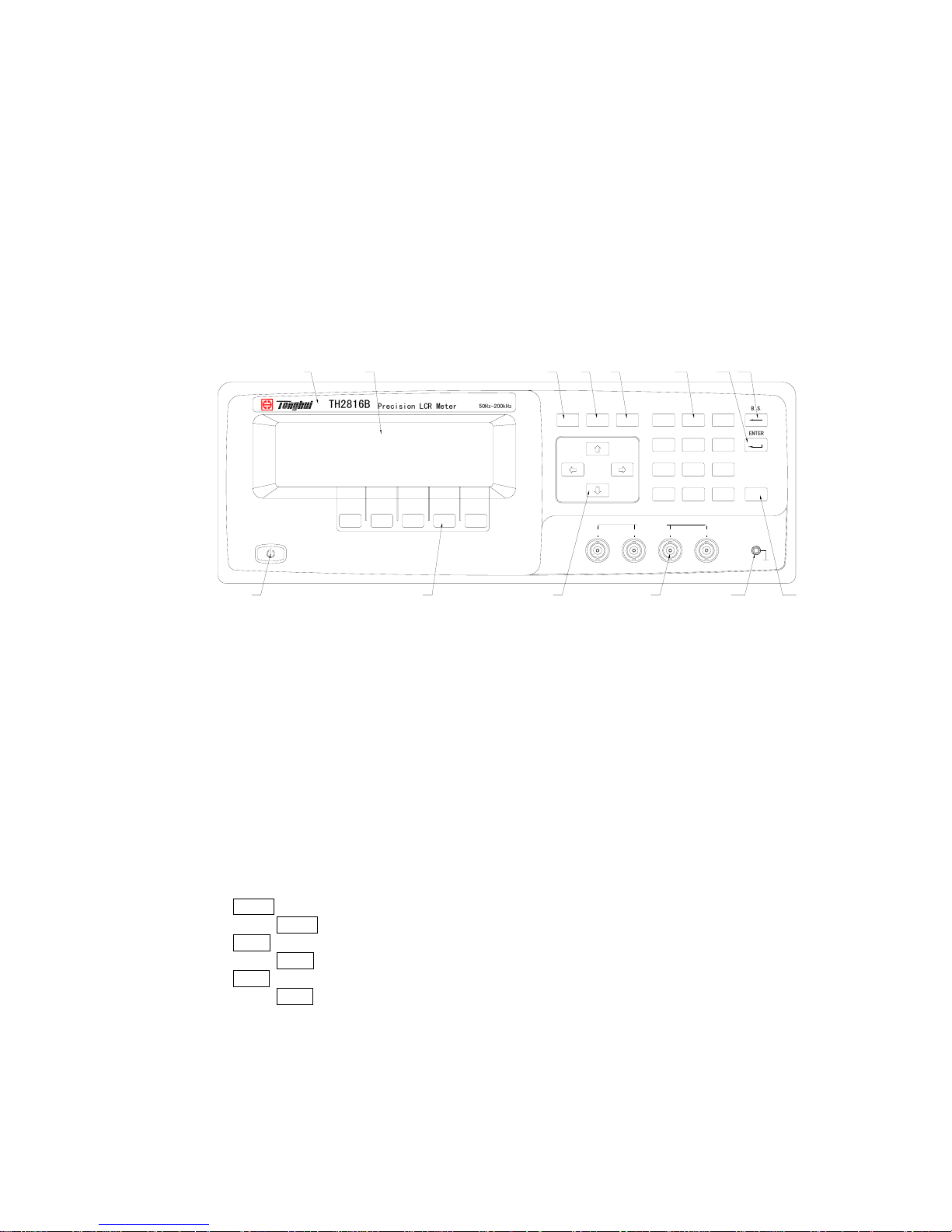
3.1 A Tour of the Front Panel
Figure 3-1 shows the brief description of key on the TH2816B’s front panel.
SYSTEMSETUPDISPLAY
B.S
.
ENTER
TRIGGER
HCURHPOTLPOTLCUR
UNKNOWN
789
456
123
0
.
-
PQRS TUV WXYZ
GHI JKL MNO
ABC DEF
Cp:206.335
D :0.00012
50Hz-200kHz
Precision LCR Meter
TH2816B
1
2
3 5 6 7 11
8 9 10
12 13
4 14
Figure 3-1. Front panel overview
1) Brand and Model
The registered brand of our company and model of the instrument are printed.
2) Power on/off
Power on/off switch. In the “ON” position all operating voltages are applied to the
instrument. In the “OFF” position NO operating voltages are applied to the
instrument.
3) LCD
240×64 dot-matrix Liquid Crystal Display (LCD) displays measurement results,
test conditions, etc.
4) SOFTKEYs
The five keys’ functions are not fixed, they have different functions in different
menus. Five softkeys are used to select control and parameter functions. Current
function of each softkey is displayed in the softkey area at the bottom of LCD.
5)
HOME menu key
Press HOME menu key to enter the Meas Display page.
6) PREV menu key
Press PREV menu key to enter the Previous page.
7) NEXT menu key
Press NEXT menu key to enter the Next page.
8) Cursor keys
The CURSOR arrow keys are used to move the field select cursor from field to
field on the LCD display page. When the cursor is moved to a field the field
changes to an inverse video image of the original field.
9) Unknown terminals
These are the UNKNOWN Terminals used to connect a four-terminal pair test
Page 15

15
fixture or test leads for measuring the device under test.
HD(H
CUR
): High current drive
HS(H
POT
): High potential sense
LS(L
POT
): Low potential sense
LD(L
CUR
): Low current drive
10) Frame terminal
This is the FRAME Terminal which is tied to the instrument's chassis and which
can be used for measurements that require guarding.
11) Number keys
The NUMBER keys are composed of the digits 0 to 9 , a period . , a minus sign
- , number keys are used to enter numeric data into the TH2816B.
12) ENTER key
ENTER terminates numeric input data and enters the displayed value in the input
window.
13)
B.S. key
BACKSPACE key deletes one last character of the input value.
14) TRIGGER key
This is the TRIGGER key used to manually trigger the TH2816B when it is set to
the Manual Trigger mode.
3.2 A Tour of the Rear Panel
Figure 3-2 gives a brief description of the TH2816B's rear panel.
INPUT
F1A
FUS
E
RS-23
2
IEEE-48
8
HANDLER
123
456
Figure 3-2. Rear panel overview
1) HANDLER Interface Connector(Optional)
This is the HANDLER interface connector used when operation with a
component handler to fully automate component testing, sorting, and quality
control data processing.
2) IEEE488 Interface Connector (Optional)
This is the IEEE488 interface connector used when operating on the General
Purpose Interface Bus.
3) RS232C Interface Connector
This is the RS232C interface connector used when operating on the serial
interface.
4) LINE Input Receptacle
Page 16
16
AC power cord receptacle.
5) Fuse Holder
Fuse holder for TH2816B line fuse, 220Vac, 1A.
6) Name Plate
Name Plate is used to provide the information of date, model, lot number and
manufacturer etc.
3.3 Display Area Definition
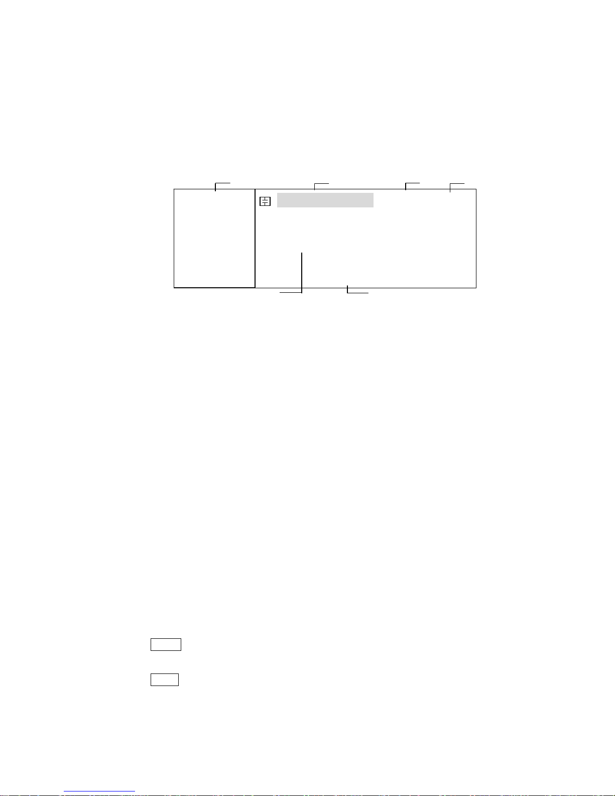
The display area on the LCD is divided into the areas show in Figure 3-3.
Figure 3-3. Display Area Definition
1) Display Page Area
This is the display page area. This area identifies the current display page.
2) Measurement Conditions area
This area is where measurement conditions are displayed.
3) File Menu Field
When the cursor is set on the File field, common file functions which are not
displayed on the display pages (for example, LOAD/Save function) are made
available.
4) Tools Menu Field
Some special controls which cannot be set on a display page's fields are made
available.
5) Measurement Date Area
This area is where measurement results are displayed.
6) Softkey Area
The bottom line is reserved for softkey labels. The softkeys displayed correspond
to the field at the cursor's position on the LCD.
3.4 MENU keys and Display Page
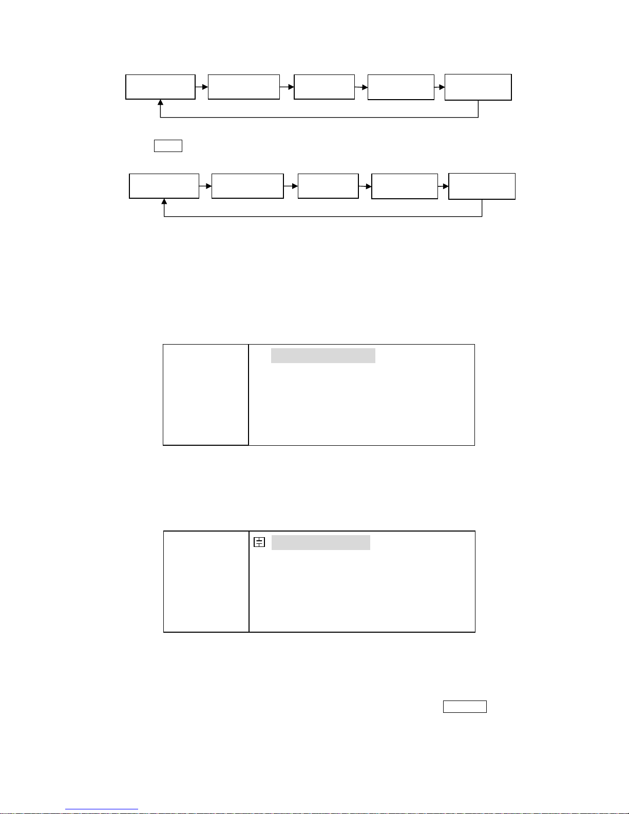
TH2816B has total file display pages:
MeasDisplay
BinNo. Disp
MeasSetup
LimitSetup
SystemConfig
TH2816B has three MENU keys which are used to switch the LCD display page.
1) HOME MENU key
This MENU key always switch to MeasDisplay page.
2) PREV MENU key
This MENU key can switch to the previous page sequentially.
FUN: Cp-D
F:1.00000k
LEV:1.000V
RANGE: AUTO
SPEED: SLOW
SHORT: OFF
OPEN : ON
< MeasDisplay> File Tools
Cp :217.324nF
D :0.00012
SYST LIMIT SETUP BinNo LCR
2 1 3 4
6
5
Page 17
17
3) NEXT MENU key
This MENU key can switch to the next page sequentially.
3.5 Summary of Pages
MeasDisplay
This display page provides the measurement result information, and some
control settings are entered from this page. TH2816B measures the DUT from
this page, and displays the measurement results in large or normal size
characters. This display page is the default display page when TH2816B is
turned on.
BinNo. Disp
This display page provides the bin sorting result information, the measurement
results, and comparator function on/off settings. The TH2816B measures the
DUT from this page. The bin number is displayed in large characters, and the
measurement results are displayed in normal size characters.
Meas Setup
This display page provides all of the measurement control settings. TH2816B
can not perform a measurement from this page, and the measurement result can
not be displayed on this page. When you want to measure the DUT using the
control settings on this page, use one of the display pages from DISPLAY menu
key.
MeasDisplay SystemConfig LimitTable MeasSetup
BinNo.Disp
MeasDisplay
BinNo.Disp
MeasSetup LimitTable
SystemConfig
FUN: Cp-D
F: 1.00000k
LEV:1.000V
RANGE: A UT O
SPEED: LOW
SHORT: OFF
OPEN : ON
< MeasDisplay> File Tools
Cp :217.324nF
D :0.00012
SYST LIMIT SETUP Bi n N o LCR
FUN: Cp-D
F: 1.00000k
LEV:1.000V
RANGE: AUTO
SPEED : LOW
SHORT: O FF
OPEN : ON
<BinNo. Disp> File Tools
COMP: ON AUX: ON
BIN : AUX
Cp : 217.324nF D : 0.00012
SYST LIMIT SETUP Bi n N o LCR
Page 18

18
Limit Table
This display page provides the limit table settings for bin sorting. TH2816B
doesn't perform measurement from this page. To see the comparison results,
either the BinNo. Disp page or the Bin Count page should be used.
System Config
This display page provides the system information and control settings, such as
LCD contrast adjustment, PASSWORD, and GPIB ADDRESS etc.
FUN: Cp-D
F: 1.00000k
LEV:1.000V
RANGE: AUTO
SPEED: LOW
CABLE: 0m
< Meas Setup> File Tools
TRIG : INT DEV_A:OFF
INT_R : 30Ω REF_A:0.00000pF
DELAY: 0ms DEV_B:OFF
Vm/Im : OFF REF_B:0.00000
SYST LIMIT SETUP Bi n N o LCR
NOMINAL:
0.00000pF
FUNC:Cp-D
MODE:±TOL
COMP: OFF
AUX : OFF
IN ALARM
< Meas Setup> File Tools
[BIN] [ LOW ] [ HIGH ]
1
2
3
2nd
SYST LIMIT SETUP Bi n N o LCR
CONTRAST
INFO BEEP
CMP ALARM
PASSWORD
BUS MODE
GPIB ADDR
AUTO FETCH
< System Config>
Selcet Item From
Left Column_
SYST LIMIT SETUP Bi n N o LCR
Page 19
19
Chapter 4 Operation
4.1 Basic operation
TH2816B's basic operation is described in the following paragraphs.
Display the desired display page using the MENU keys and the softkeys. (Refer
to Figure 3-1.)
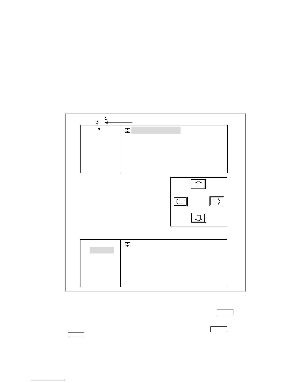
Move the CURSOR to the field to be used using the CURSOR keys. The cursor
will be an inverse video marker, and the field is an area at which you can set the
CURSOR. (Refer to Figure 4-1.)
Figure 4-1. CURSOR Keys and Field Operation Example
The softkeys corresponding to the field pointed to by the CURSOR will be
displayed. Select and press a softkey. The numeric entry keys and ENTER are
used to enter numeric data. (Refer to Figure 4-2.)
When one of the numeric entry keys is pressed, the softkeys will change to the
available unit softkeys. You can use these unit softkeys instead of ENTER. When
ENTER is used, the numeric data is entered with Hz, V, or A as the default unit
depending on the cursor field selected, for example, the test frequency's unit will be
Hz, etc.
FUN: Cp-D
F: 1.00000k
LEV:1.000V
RANGE: A UT O
SPEED: LOW
SHORT: OFF
OPEN : ON
< MeasDisplay> File Tools
Cp :217.324nF
D :0.00012
SYST LIMIT SETUP Bi n N o LCR
FUN: Cp-D
F: 1.00000k
LEV:1.000V
RANGE: A UT O
SPEED: LOW
SHORT: OFF
OPEN : ON
< MeasDisplay> File Tools
Cp :217.324nF
D :0.00012
ª(--) (-) (+) ©(++)
1
2
Page 20

20
<MeasDispaly>
SPEED: SLOW
OPEN: ON
SHORT: OFF
Cp-D
RANGE: AUTO
LEV: 1.000V
FRQ: 1.0kHz
FUN: Cp-D
Cs-Rs
Cp:206.335nF
D :0.00012
Cp-RpsCs-D
File
NEXT
Tools
Figure 4-2. Softkey Selection Example
4.2 Welcome Page
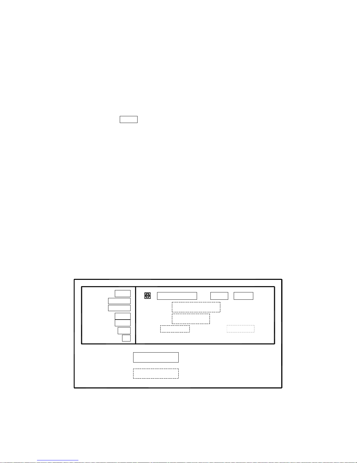
Press the power switch to turn on TH2816B, the welcome page will display as shown
in Figure 4-3. The name of the instrument with its version will also be displayed. If
password function is ON, you must input the correct password to start the instrument.
If you input a wrong password for three times, the instrument will be locked. You must
turn off the power and then turn on the power again in order to try another password.
(Refer to Figure 4-4)
Figure 4-3. Welcome Page
Figure 4-4. Input the Password
Note: TH2816B’s factory default password is “2816”.
Page 21
21
4.3 Detailed Operation
This Chapter provides information about the function of each page.
MeasDisplay
BinNo. Disp
MeasSetup
LimitSetup
SystemConfig
This Chapter describes the functions on each page in the order of the preceding list.
4.3.1 MeasDisplay Page
When you press HOME, the MeasDisplay page will be displayed. On this page, the
measurement results are displayed in large characters, and the following
measurement controls can be set from this page. (The field in parenthesis is used to
set the control function.)
Measurement Function (FUN)
Test Frequency (FRQ)
Oscillator Level (LEV)
Measurement Range (RANGE)
Measurement Speed (SPEED)
Short Correction (SHORT)
Open Correction (OPEN)
File Management (File)
Useful Tools (Tools)
There are ten fields on this page: <MeasDisplay>, FUN, FRE, LEV, RANGE, SPEED,
SHORT, OPEN, File and Tools. Each control function is described in the following
paragraphs.
This page also provides the oscillator level voltage/current monitor value information
in monitor areas on the displayed page. These conditions can be set from the Meas
Setup page.
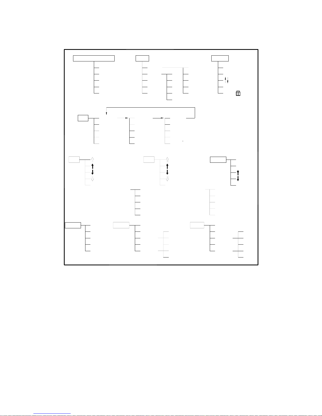
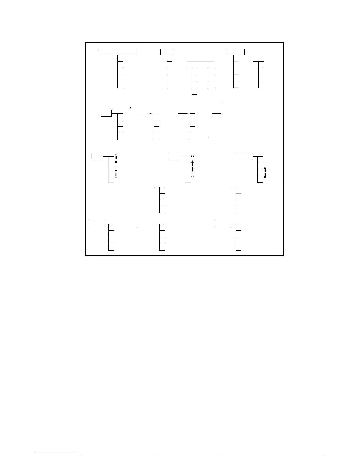
The available fields and the softkeys which correspond to the fields on this page are
shown in Figure 4-5 and Figure 4-6 respectively.
Vm:999.1mV
<MeasDisplay>
Cp:206.335nF
D :0.00012
SHORT: OFF
OPEN: ON
SPEED: SLOW
RANGE: AUTO
LEV: 1.000V
FRQ: 1.0kHz
FUN: Cp-D
Im:1.364mA
BinNo
Tools
: Field
: Monitor
COUNTSWEEP
File
LCR
Figure 4-5. Available Fields on the MeasDisplay Page
Page 22
22
Ls-Q
Ls-Rs
Lp-Q
Lp-Rp
NEXT
File
Cs-Rs
(TH2816A)
Cs-D
Cp-D
SLOW
FAST
(--)
(++)
Cp-Rp
[NUMERIC ENTRY]
SPEED
MED
FRQ
(-)
(+)
SHORT
NEXT
LCR
BinNo.
COUNT
SWEEP
<MeasDisplay>
FUN
ESC ESC
RANGE
Tools
G-B
(++)
(--)
ZZ-
R-X
[NUMERIC ENTRY]
Hz
ON
ShSWP
ShCLR
OFF
ESC
kHz
LEV
(-)
(+)
OPEN
θ
θ
r
NEXT
OK
ESC
LOAD
SAVE
ESC
mV
ON
OFF
OpSWP
OpCLR
ESC
V
AUTO
(+)
(-)
HOLD
FIX B
FIX A
KEY
Figure 4-6. Available Softkeys on the MeasDisplay Page
4.3.1.1 Measurement Function
TH2816B measures two components of the complex impedance (parameters) at the
same time in a measurement cycle. The measurement parameters are listed as
follows.
Primary Parameters
|Z| (absolute value of impedance)
L (inductance)
C (capacitance)
R (resistance)
Secondary Parameters
D (dissipation factor)
Q (quality factor)
Rs (equivalent series resistance)
Page 23
23
Rp (equivalent parallel resistance)
X (reactance)
Θ (phase angle)
The primary parameter measurement result is located on the upper line as two large
character lines on this page, and the secondary parameter measurement result is
located on the lower line as two large character lines on this page.
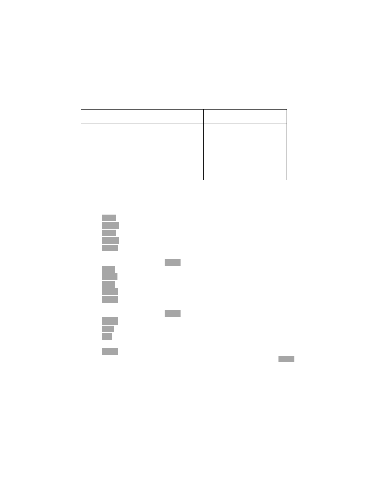
The combinations of primary and secondary parameters, including the equivalent
parallel and serial combinations, are listed in Table 4-1.
Table 4-1. Measurement Function
Primary
Parameter
Serial Mode Parallel Mode
Z
Z-Θr
Z-Θ°
C
Cs-D
Cs-Rs
Cp-D
Cp-Rp
L
Ls-Q
Ls-Rs
Lp-Q
Lp-Rp
R R-X
Front Panel Operation for Setting the Measurement Function
Perform the following steps to set the measurement function.
1) Use the CURSOR arrow keys to move the cursor to the FUN field. The following
softkeys will be displayed.
Cp-D
Cp-Rp
Cs-D
Cs-Rs
NEXT
2) Select and press a softkey to set the measurement function. If the softkey you
want is not displayed, press NEXT to display the following set of softkeys.
Ls-Q
Ls-Rs
Lp-Q
Lp-Rp
NEXT
3) Select and press a softkey to set the measurement function. If the softkey you
want is not displayed, press NEXT to display the following set of softkeys.
Z-Θ°
Z-Θr
R-X
NEXT
4) Select and press a softkey to set the measurement function. When NEXT is
pressed, the softkeys shown in step 1 will be displayed. Retry steps 1 through 4 if
you missed the function you were looking for.
4.3.1.2 Test Frequency
TH2816B operates from 50 Hz to 200 kHz with 37 typical frequency points which can
be selected through softkeys, or set through numeric entry keys.
Front Panel Operation for Setting the Test Frequency
Perform the following steps to set the test frequency.
Page 24
24
1) Move the CURSOR to the FRQ field. The following softkeys will be displayed.
⇓(--)
This softkey is the coarse frequency decrement softkey which is used to
decrease the test frequency to the next sequentially lower tenth value after
50 Hz. The frequency points set using this softkey are as follows.
50 Hz 100 Hz 1.0 kHz 10 kHz 100 kHz 200 kHz
↓(-)
This softkey is the fine frequency decrement softkey used to decrease the
test frequency to the next sequentially lower frequency point. The sequential
frequency points which can be set using this softkey are as follows.
50Hz 60Hz 80Hz 100Hz 120Hz 150Hz 200Hz 250Hz
300Hz 400Hz 500Hz 600Hz 800Hz 1kHz 1.2kHz 1.5kHz
2kHz 2.5kHz 3kHz 4kHz 5kHz 6kHz 8kHz 10kz
12kHz 15kHz 20kHz 25kHz 30kHz 40kHz 50kHz 60kHz
80kHz 100kHz 120kHz 150kHz 200kHz
If the input frequency is not the one supported by TH2816B, the TH2816B
will automatically modify to the frequency point which is the nearest higher
point.
↑(+)
This softkey is the fine frequency increment softkey used to increase the
current test frequency to the next sequentially higher frequency point. The
frequency points set using this softkey are the same values as set using
↓(-).
⇑(++)
This softkey is the coarse frequency increment softkey used to increment
the test frequency to the next sequentially higher tenfold value after 50 Hz.
The frequency points set using this softkey are the same as the frequency
points set using ⇓(--).
4.3.1.3 Oscillator Level
TH2816B’s oscillator level can be set as the effective value (RMS value) of a sine
wave of the test frequency from TH2816B's internal oscillator. The oscillator level can
be set from 0 V
rms
to 2.00 V
rms
with a 0.01 V
rms
resolution. The output impedance can
be selected either 30Ω or 100Ω.
Note: The set value of the oscillator voltage level is the value set when the
measurement contacts (UNKNOWN Terminals) are opened.
Front Panel Operation for Setting the Oscillator Level
There are two ways to set the oscillator level. One is to use the softkeys, and the
other is to use the use the numeric entry keys.
Perform the following steps to set the oscillator level.
1) Move the cursor to the LEV field. The following softkeys will be displayed.
⇓(--)
This softkey is the coarse level decrement softkey which is used to decrease
the test signal level by a 0.1 V
rms
step.
↓(-)
This softkey is the fine level decrement softkey which is used to decrease
the test signal level by a 0.01 V
rms
step.
↑(+)
This softkey is the fine level increment softkey which is used to increase the
test signal level by a 0.01 V
rms
step.
Page 25
25
⇑(++)
This softkey is the coarse level increment softkey which is used to increase
the test signal level by a 0.01 V
rms
step.
2) Select and set the oscillator level using either the softkeys or the numeric entry
keys. When the oscillator level is entered using the numeric entry keys, the
softkey labels are changed to the available units labels (mV, V), and you can use
these softkeys to enter the units and enter the data instead of ENTER. When
ENTER is used, the numeric data is entered with V as the default unit.
4.3.1.4 Measurement Range
TH2816B has nine measurement ranges: 10Ω, 30Ω,100Ω, 300Ω, 1 kΩ, 3 kΩ, 10
kΩ, 30 kΩ, and 100 kΩ. The measurement range is selected according to the DUT's
impedance even if measurement parameter is capacitance or inductance. Table 4-2
shows the effective measuring range for each measurement range while in the
impedance mode (|Z|, R, X).
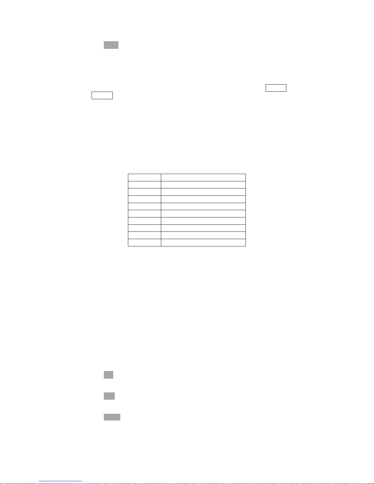
Table 4-2. Measurement Range for Each Range
RANGE MEASUREMENT RANGE
10 Ω 0 Ω to 10 Ω
30 Ω 10 Ω to 100 Ω
100 Ω 100 Ω to 316 Ω
300 Ω 316 Ω to 1 kΩ
1 kΩ 1 kΩ to 3.16 kΩ
3 kΩ 3.16 kΩ to 10 kΩ
10 kΩ 10 kΩ to 31.6 kΩ
30 kΩ 31.6 kΩ to 100 kΩ
100 kΩ More than 100 kΩ
When the measurement range is set manually, the optimum measurement range
should be selected by matching the DUT's impedance to the measurement range
shown in Table 4-2. When the measurement range is set to AUTO, the optimum
measurement range is automatically selected according to the impedance of each
DUT.
Note: The measurement range is limited by the test frequency setting, when the
oscillator level is equal to 2 V or less than 2 V. When the measurement
range and the test frequency are set under the above conditions, the test
frequency must be set first, and then the measurement range. If you set the
measurement range first and then frequency, the resulting measurement
range may not be the one you wanted to set.
Front Panel Operation for Setting the Measurement Range
Perform the following procedure to set the measurement range.
1) Move the cursor to the RANGE field using the CURSOR keys. The following
softkeys will be displayed.
↓(-)
This softkey is used to decrease the measurement range in the HOLD (fixed
range) mode.
↑(+)
This softkey is used to increase the measurement range in the HOLD (fixed
range) mode.
HOLD
This softkey is used to change the measurement range from the AUTO
mode to the HOLD mode. When the measurement range is set to the HOLD
mode, the impedance range is fixed at the current range setting, and the
Page 26
26
impedance range is displayed in the RANGE field.
AUTO
This softkey is used to set the measurement range to AUTO.
2) Use the softkeys to set the measurement range.
4.3.1.5 Measurement Speed
TH2816B's measurement speed is determined by the following conditions.
Integration Time (A/D conversion)
Averaging Rate (number of measurement averaged)
Delay Time (time delay between the trigger and the start of the
measurement)
Measurement result's display time.
Generally, a slow measurement speed will result in more stable and accurate
measurement results. SLOW, MED, and FAST measurement speed can be set.
Front Panel Operation for Setting the Measurement Speed
Perform the following steps to set the measurement speed.
1) Move the cursor to the SPEED field. The following softkeys will be displayed.
FAST
MED
SLOW
2) Use the preceding softkeys to select and set the measurement speed.
4.3.1.6 Short Correction
TH2816B's SHORT correction capability corrects for the residual impedance (R, X) in
serial with the device under test.
Front Panel Operation for the Short Correction
There are two procedures: SHORT correction at all frequency points, and SHORT
correction at the current test frequency point.
Perform the following steps to execute SHORT correction.
1) Move the cursor to the SHORT field. The following softkeys will be displayed.
ShSWP
ShCLR
OFF
ON
2) Connect the test fixture to the UNKNOWN Terminals, and short the measurement
contacts together.
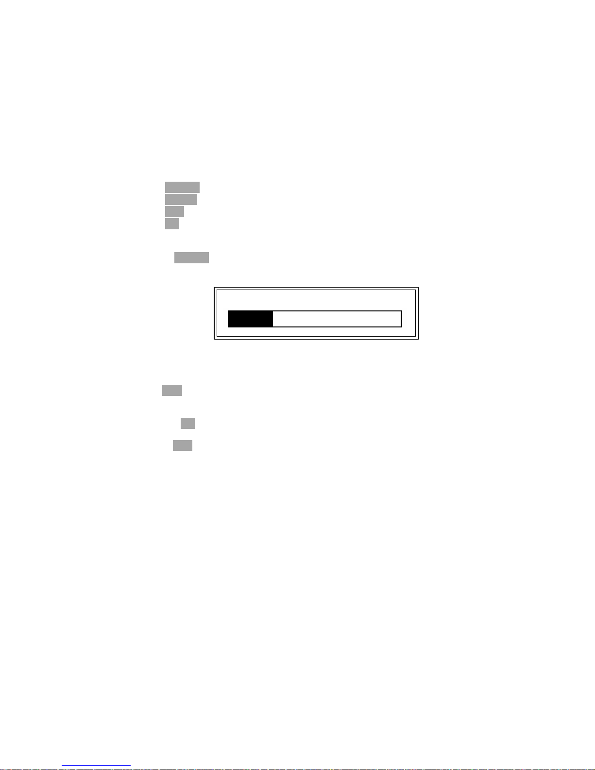
3) Press ShSWP. TH2816B will measure the short impedance (inductance and
resistance) at all frequency points. Figure 4-7 shows the short correction
information.
Figure 4-7. Short Correction Information
During the SHORT correction measurement cycle, the following softkey is
available.
ESC
This softkey is used to stop the short correction data measurement. The
previous SHORT correction data is still stored.
4) Press ON to perform SHORT correction calculations on subsequent
measurements.
5) Press OFF to halt SHORT correction calculations on subsequent measurements.
Shorting 1kHz
Page 27
27
4.3.1.7 Open Correction
TH2816B's OPEN correction capability corrects errors due to the stray admittance (G,
B) in parallel with the device under test.
Front Panel Operation for the Open Correction
There are two procedures: OPEN correction at all frequency points, and OPEN
correction at the current test frequency point.
Perform the following steps to execute OPEN correction.
1) Move the cursor to the OPEN field. The following softkeys will be displayed.
OpSWP
OpCLR
OFF
ON
2) Connect the test fixture to the UNKNOWN Terminals without connecting the
device under test.
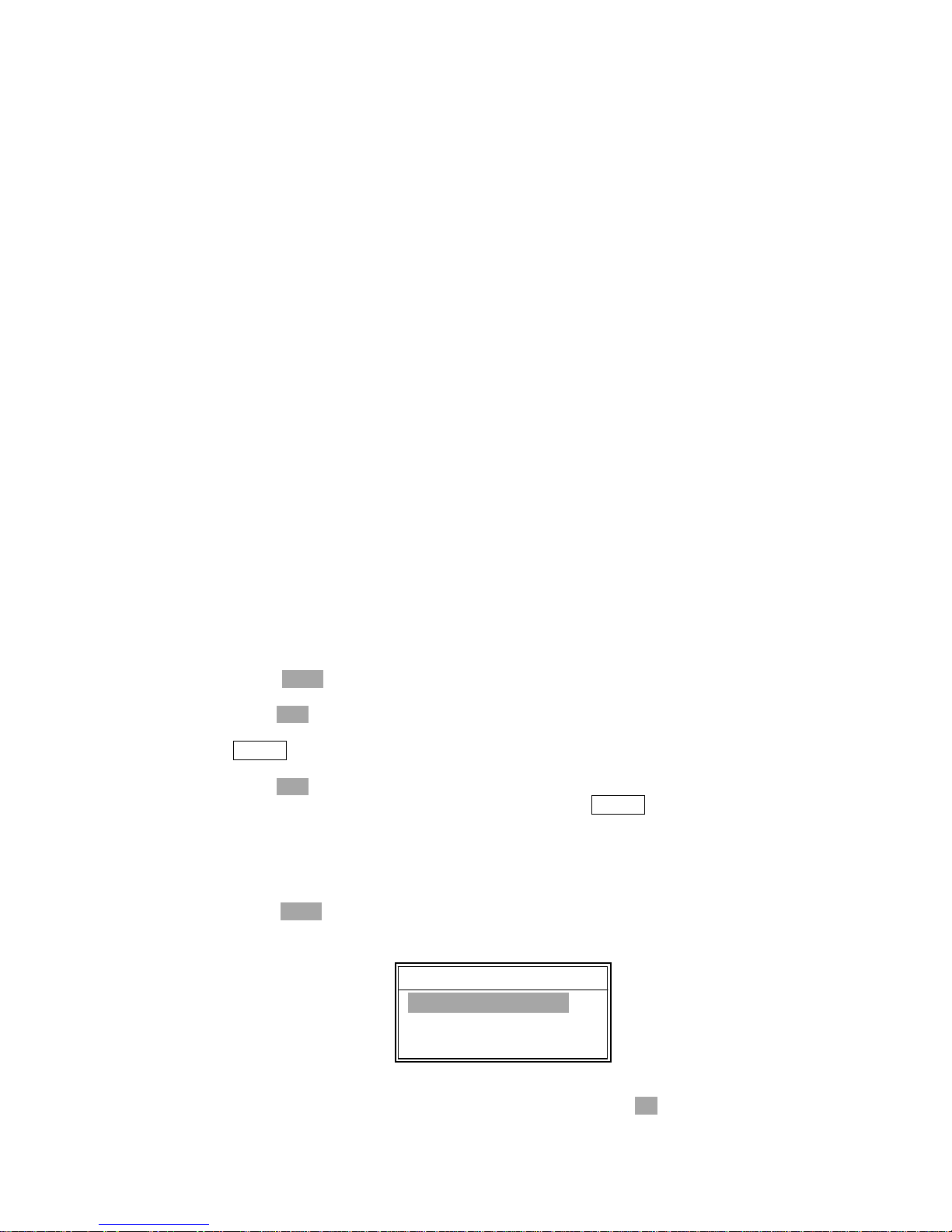
3) Press OpSWP. TH2816B will measure the open admittance (capacitance, and
inductance) at all frequency points. Figure 4-8 shows the open correction
information.
Figure 4-8. Open Correction Information
During the OPEN correction measurement cycle, the following softkey is
available.
ESC
This softkey is used to stop the OPEN correction data measurement. The
previous OPEN correction data is still stored.
4) Press ON to perform OPEN correction calculations on subsequent
measurements.
5) Press OFF to halt OPEN correction calculations on subsequent measurements.
4.3.1.8 File Management
TH2816B uses the internal non-volatile memory for storing and retrieving a maximum
of 12 sets of instrument control settings. The following data will be stored in
non-volatile memory as one file.
Control settings on the Meas Setup page.
Measurement Function
Test Frequency
Oscillator Level
Measurement Range
Measurement Speed
Trigger Mode
Output Impedance
Delay Time
Averaging Rate
Deviation Measurement A/B(ΔABS/Δ%/off)
Deviation Measurement AB Reference Value
Control settings on the Limit Table page.
Nominal Value
Measurement Function (Swap Parameter)
Limit Mode for the Primary Parameter
Comparator Function on/off
Opening 1kHz
Page 28
28
Auxiliary Bin on/off
Alarm on/off
Low/High Limits for Each Bin
Display page format
When TH2816B is turned on, TH2816B's auto load function will load the control
settings stored in file number 0. If there are no control settings stored in file number 0,
the power-on default settings will be used.
The following items are stored in internal nonvolatile memory without using the
LOAD/SAVE function.
Control settings on the User Correction page.
OPEN, SHORT, LOAD correction on/ff
OPEN, SHORT correction data for all test frequencies.
OPEN, SHORT, LOAD correction data at FREQ1, FREQ2, and FREQ3.
(OPEN correction data at each frequency, SHORT correction data at
each frequency, and LOAD correction reference data and actual data at
each frequency.)
Control settings on the System Config page.
Contrast of LCD
Information Beeper on/off
Comparator Alarm on/off
Password
Bus Mode
GPIB address
AutoFetch on/off
Perform the following steps to save the control settings to the internal non-volatile
memory.
1) Select and set all control settings on the MeasDisplay page.
2) Move the cursor to the File field.
3) Press SAVE. The message “Enter save number” will be displayed in the
message window.
4) Press ESC to cancel the number input operation.
5) Enter a save number from 0 to 11 using the numeric entry keys and press
ENTER. The message “Enter File Name” will be displayed in the message
window.
6) Press ESC to cancel the file name input operation.
7) Enter a file name using the numeric entry keys and ENTER to save the current
control settings. Numeric digits and characters can be inputted as a file name.
Perform the following steps to load the control settings from the internal non-volatile
memory.
1) Move the cursor to the File field.
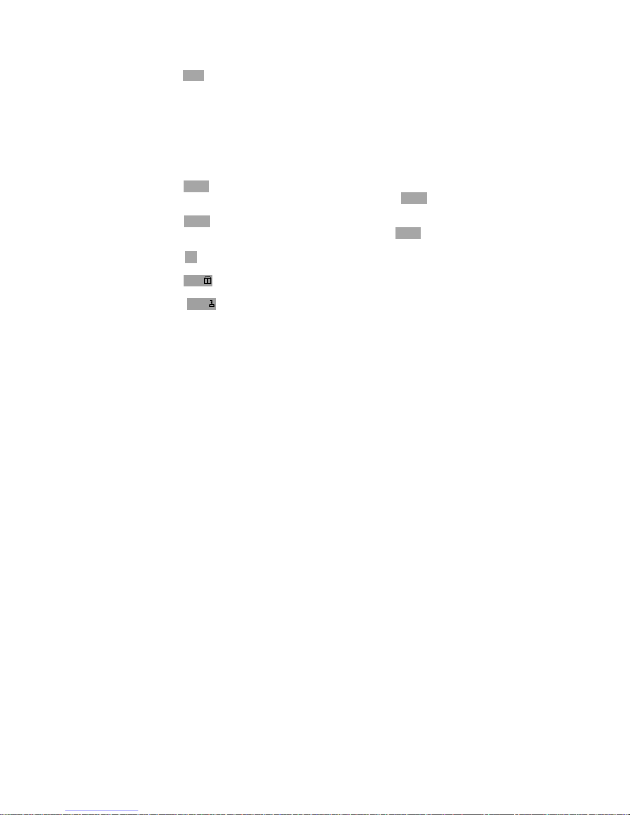
2) Press LOAD. The message of available file(s) will be listed in the message
window as shown in Figure 4-9.
Figure 4-9. Available Files Message Window
3) Use the up and down cursor keys to select a file and press OK to load the file.
Load File:No.1
CBB13-325J
<Unnamed>
*TH2816B*
Page 29
29
4) Press ESC to cancel the load file operation.
4.3.1.9 Useful Tools
TH2816B displays the measurement data using a six digit floating point display
format. The fixed decimal point function is used to display the measurement data
using a fixed point display format. This function can also be used to change the
number of digits displayed.
Perform the following steps to use the xed decimal point function.
1) Move the cursor to the Tools field.
2) Press FIX A to fix the decimal point for the main parameter's data. The “_” mark
will be displayed at the decimal fixed point. Each time FIX A is pressed, the last
digit is dropped, the value is rounded off.
3) Press FIX B to fix the decimal point for the sub parameter's data. The “_” mark
will be displayed at the decimal fixed point. Each time FIX B is pressed, the value
is rounded off giving one less digit.
4) Press ↑↓ to switch the measurement result display characters between large
character and normal character.
5) Press KEY to lock the keyboard and “KeyLocked !” message will be displayed
in the message window.
6) Press KEY to unlock the keyboard and “KeyUnlock !” message will be
displayed in the message window.
Note: When the measurement function is changed, the fixed decimal point function
is automatically disabled.
Page 30
30
4.3.2 Bin Number Display Page
When you press PREVorNEXT, or BinNo softkey, the BinNo. Disp page will be
displayed. The bin sorting results are displayed in large characters and the
measurement results are displayed in normal characters on the BinNo. Disp page,
and the following measurement controls can be set from the BinNo. Disp page. (The
field in parenthesis is used when this control is set.)
Comparator Function ON/OFF (COMP)
Auxiliary Bin ON/OFF (AUX)
File Management (File)
Useful Tools (Tools)
There are five fields on this page: <BinNo. Disp>, COMP, AUX, File, and Tools
fields.
Each control is described in the following paragraphs.
This page also provides the following information in the monitor areas (each monitor
area looks like a field, but is not). These conditions can be set from the Meas Setup
page, and most conditions can be set from the MeasDisplay page.
Measurement Function (FUN)
Test Frequency (FRQ)
Oscillator Level (LEV)
Measurement Range (RANGE)
Measurement Speed (SPEED)
Open Correction (OPEN)
Short Correction (SHORT)
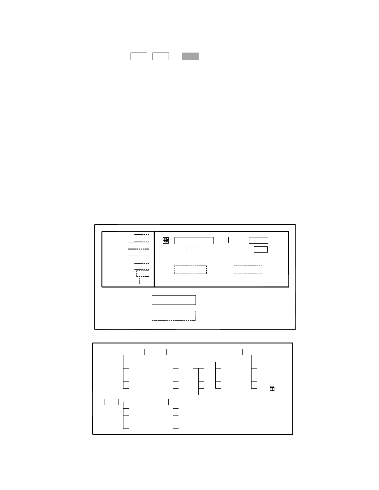
The available fields and the softkeys which correspond to each field on this page are
shown in Figure 4-10 and Figure 4-11.
: Field
: Monitor
Cp:206.335nF D :0.00012
COUNT
FUN: Cp-D
FRQ: 1.0kHz
LEV: 1.000V
SHORT: OFF
OPEN: ON
SPEED: SLOW
RANGE: AUTO
SWEEP
COMP : OFF
<BinNo. Disp>
BIN:
LCRBinNo
Tools
AUX : OFF
File
Figure 4-10 Available Fields on the BinNo. Disp Page
File
ON
OFF
LCR
BinNo.
COUNT
SWEEP
<BinNo. Disp>
COMP
AUX
Tools
OK
ESC
LOAD
SAVE
OFF
ON
ESC KEY
Figure 4-11 Available Softkeys on the BinNo. Disp Page
Page 31
31
4.3.2.1 Comparator Function ON/OFF
TH2816B's built-in comparator can sort devices into a maximum of 10 bins (BIN 1 to
BIN 9 and the OUT bin) using a maximum of 3 pairs of primary limits and one pair of
secondary parameter limits. Also, a device whose primary parameter is within limits,
but whose secondary parameter measurement result is not within limits can be sorted
into an AUXiliary BIN. The comparator function is especially useful when using
TH2816B with a component handler. These limit settings for bin sorting are only set
on the Limit Table page under SETUP menu. So this COMP field allows you to only
set the comparator function to ON or OFF.
Front Panel Operation for Setting the Comparator Function to ON or OFF
Perform the following steps to set the comparator function to ON or OFF.
1) Move the cursor to the COMP field. The following softkeys will be displayed.
ON
OFF
2) Use the softkeys to set the comparator function to ON or OFF.
4.3.2.2 Auxiliary Bin ON/OFF
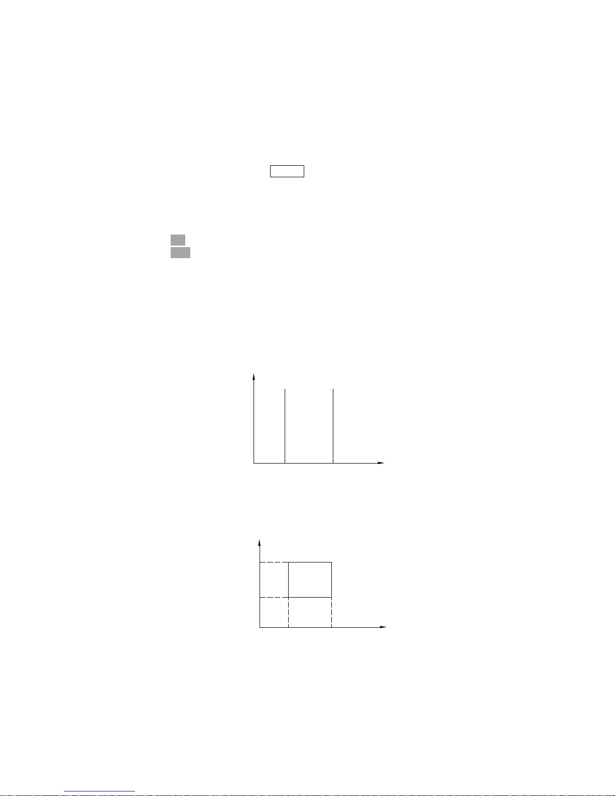
When the secondary parameters affect the sorting results, the limits for the secondary
parameter can be set in 2nd LOW/HIGH fields. So there are four patterns for the
sorting area of the secondary parameter.
When the secondary parameter limits are not specified on the Limit Table page.
Devices will be sorted according to primary parameter comparison results.
BIN
Sorting
Secondary
Parameter
OUT
OF
BINS
Lower
Limit
Higher
Limit
OUT
OF
BINS
Primary
Parameter
When the secondary parameter limits are set and AUX BIN are set to OFF.
Only devices with secondary limits are sorted by the primary parameter result.
Devices not within the secondary parameter limits are sorted OUT OF BINS even
if the device's primary parameter is within limits.
OUT OF
BINS
OUT OF
BINS
BIN
Sorting
Higher
Limit
Lower
Limit
Secondary
Parameter
OUT
OF
BINS
Lower
Limit
Higher
Limit
OUT
OF
BINS
Primary
Parameter
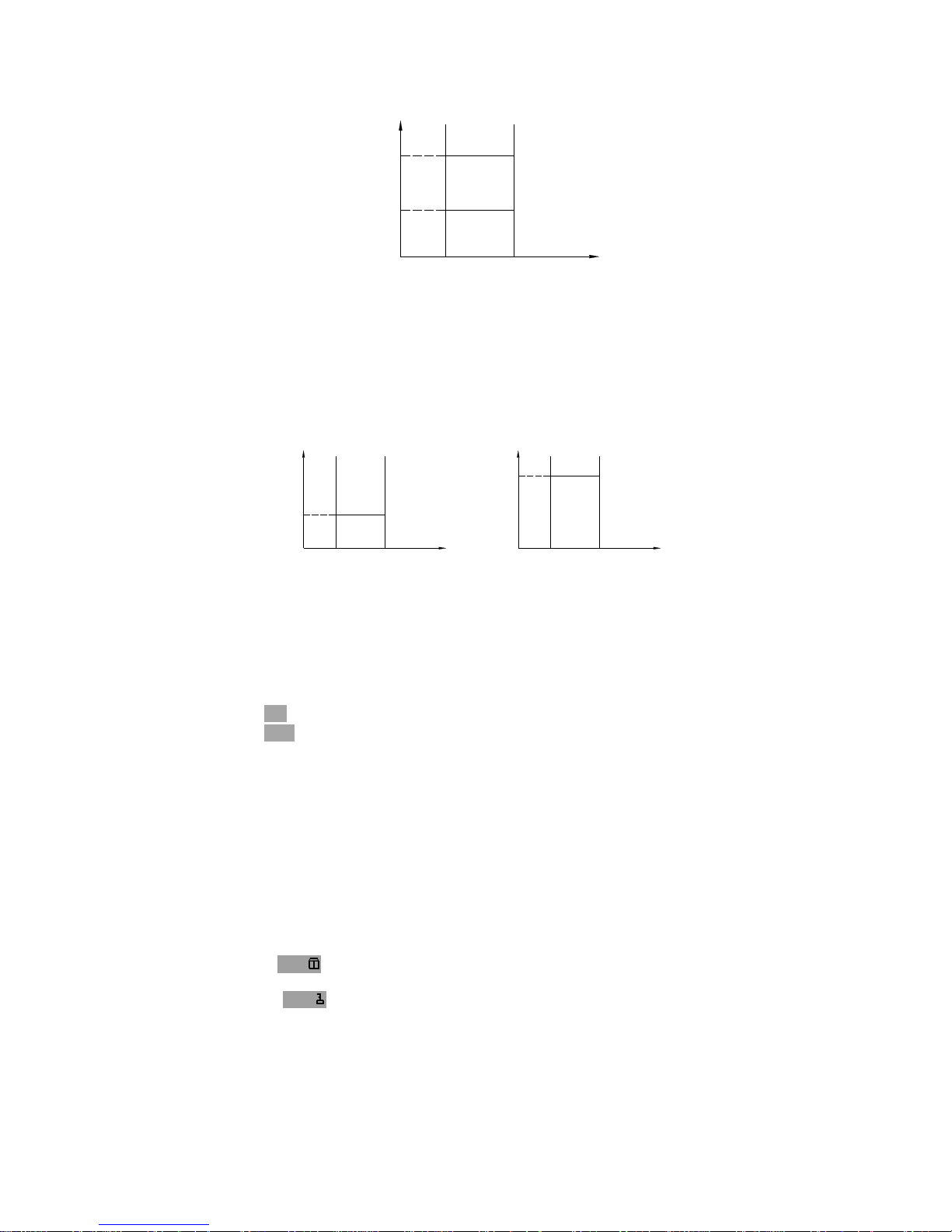
When the secondary parameter limits are set and AUX BIN are set to ON.
Devices whose primary parameter is not within limits are sorted OUT OF BINS.
Devices whose primary parameter is within limits, but whose secondary
parameter is out of limits are sorted into the AUX BIN.
Page 32
32
AUX
BINS
AUX
BINS
BIN
Sorting
Higher
Limit
Lower
Limit
Secondary
Parameter
OUT
OF
BINS
Lower
Limit
Higher
Limit
OUT
OF
BINS
Primary
Parameter
When only the lower limit of the secondary parameter is set and the AUX BIN are
set to ON, the devices whose primary parameter is within limits, but whose
secondary parameter is equal to or below the lower limit are sorted into the AUX
BIN. Also when only the higher limit of the secondary parameter is set and the
AUX BIN are set to ON, the devices whose primary parameter is within limits, but
whose secondary parameter is equal or above the higher limit are sorted into the
AUX BIN. (See below.)
Lower
Limit
Secondary
Parameter
Lower
Limit
OUT
OF
BINS
OUT
OF
BINS
AUX
BINS
BIN
Sorting
Higher
Limit
Primary
Parameter
Higher
Limit
Lower
Limit
OUT
OF
BINS
Higher
Limit
Secondary
Parameter
AUX
BINS
BIN
Sorting
Primary
Parameter
OUT
OF
BINS
The AUX field allows you to set the AUX BIN to ON or OFF.
Front Panel Operation for Setting the AUX BIN to ON or OFF
Perform the following steps to set the AUX BIN to ON or OFF.
1) Move the cursor to the AUX field. The following softkeys will be displayed.
ON
OFF
2) Select and press a softkey to set AUX BIN to ON or OFF.
4.3.2.3 File Management
This function is the same as the function on the MeasDisplay page (Refer to 4.3.1.8
File Management.)
4.3.2.4 Useful Tools
The key lock function is used to disable all front panel operation.
Perform the following steps from the BinNo. Disp page to disable or enable all front
panel operation.
1) Move the cursor to the Tools field.
2) Press KEY to lock the keyboard and “KeyLocked !” message will be displayed
in the message window.
3) Press KEY to unlock the keyboard and “KeyUnlock !” message will be
displayed in the message window.
Page 33
33
4.3.3 Meas Setup Page
When you press PREVorNEXT, or SETUP softkey,the Meas Setup page can be
displayed. On this Meas Setup page, all of the following measurement control
functions can be set. (Each field in parenthesis is used when each control is set.)
Measurement Function (FUN)
Test Frequency (FRQ)
Oscillator Level (LEV)
Measurement Range (RANGE)
Measurement Speed (SPEED)
Short Correction (SHORT)
Open Correction (OPEN)
Trigger Mode (TRIG)
Output Signal impedance (INT_R)
Delay Time (DELAY)
Averaging Rate (AVG)
Signal Level Monitor ON/OFF (Vm/Im)
Deviation Measurement A Mode (DEV_A)
Deviation Measurement B Mode (DEV_B)
Reference Value for the Deviation Measurement A (REF_A)
Reference Value for the Deviation Measurement B (REF_B)
File Management (File)
Useful Tools (Tools)
Following fields on the Meas Setup page are the same as the fields on the
MeasDisplay page as follows. So, these fields are not described in this Chapter, and
the other functions on the Meas Setup page are described in the following
paragraphs.
Measurement Function (FUN)
Test Frequency (FRQ)
Oscillator Level (LEV)
Measurement Range (RANGE)
Measurement Speed (SPEED)
Short Correction (SHORT)
Open Correction (OPEN)
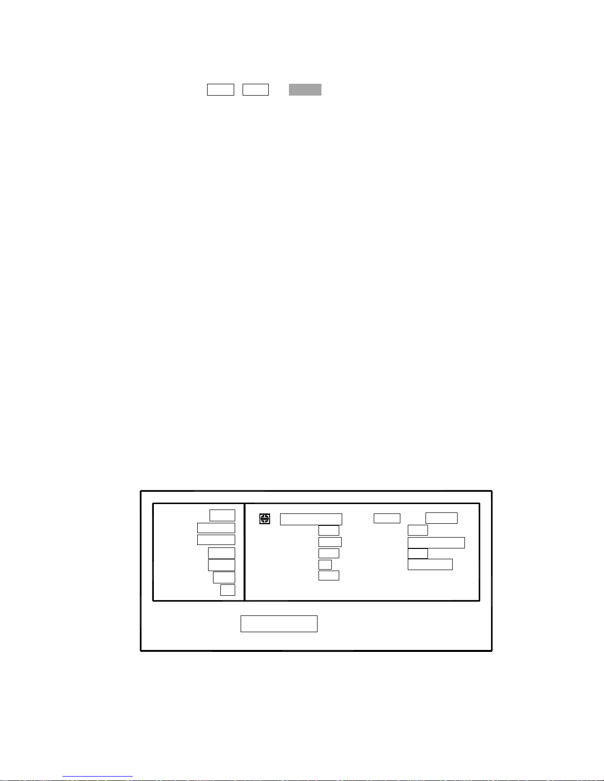
The available fields and the softkeys which corresponded to each field on this page
are shown in Figure 4-12 and Figure 4-13.
: Field
LIMIT
FUN: Cp-D
FRQ: 1.0kHz
LEV: 1.000V
RANGE: AUTO
SHORT: OFF
OPEN: ON
SPEED: SLOW
Vm/Im:
AVG :
DELAY :
INT R :
TRIG :
<Meas Setup>
OFF
1
0ms
30
Ω
INT
LIST
REF B:0.00000
DEV B:OFF
REF A:0.00000pF
DEV A:OFF
Tools
-
-
-
-
CORR
File
SETUP
Figure 4-12. Available Fields on the MEAS SETUP Page
Page 34
34
Ls-Q
Ls-Rs
Lp-Q
Lp-Rp
NEXT
File
Cs-Rs
(TH2816A)
Cs-D
Cp-D
SLOW
FAST
(--)
(++)
Cp-Rp
[NUMERIC ENTRY]
SPEED
MED
FRQ
(-)
(+)
SHORT
NEXT
SETUP
CORR
LIMIT
LIST
<Meas Setup>
FUN
RANGE
Tools
G-B
(+)
(++)
(--)
(-)
ZZ-
R-X
[NUMERIC ENTRY]
Hz
ON
OFF
ESC
kHz
LEV
OPEN
θ
θ
r
NEXT
OK
ESC
LOAD
SAVE
ESC
HOLD
AUTO
mV
ON
OFF
ESC
V
(+)
(-)
CLEARNOYES
Figure 4-13. Available Softkeys on the MEAS SETUP Page (1/2)
Page 35
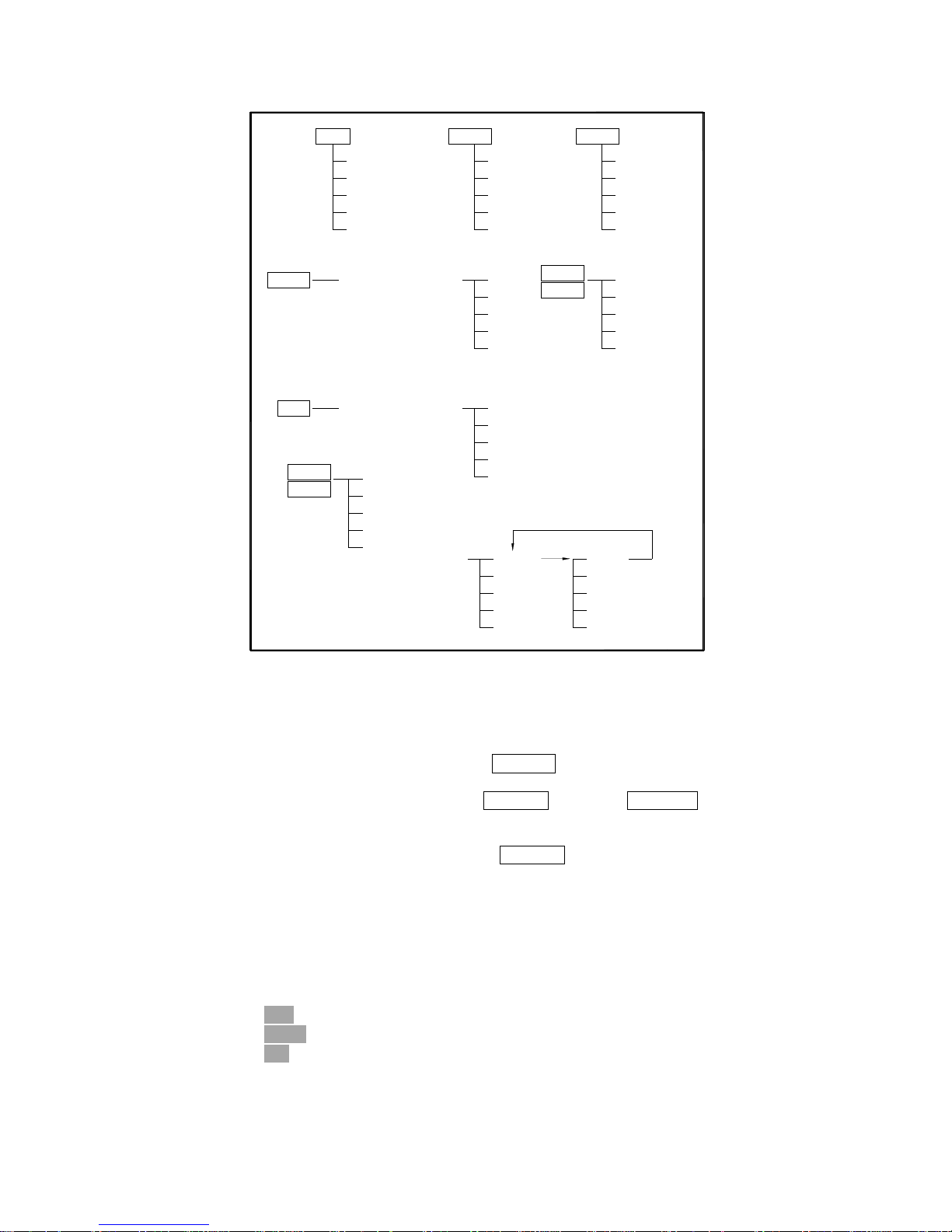
35
[NUMERIC ENTRY]
[NUMERIC ENTRY]
[NUMERIC ENTRY]
-
REF B
AVG
REF A
-
MEAS
TRIG
DELAY
EXT
INT
MAN
ESC
M
m
NEXT
Vm/Im
ESC
NEXT
ESC
ESC
p
μ
n
k
sec
msec
100
Ω
30Ω
-
INT R
DEV B
DEV A
-
Δ %
OFF
Δ ABS
OFF
ON
Figure 4-13. Available Softkeys on the MEAS SETUP Page (2/2)
4.3.3.1 Trigger Mode
TH2816B has four trigger modes: INTernal, EXTernal, MANual, and BUS.
When the trigger mode is set to INT trigger mode, TH2816B continuously repeats
measurements on any display page under DISPLAY.
When the trigger mode is set to MAN trigger mode, TH2816B performs a single
measurement on any display page under DISPLAY every time TRIGGER on the front
panel is pressed.
When the trigger mode is set to EXT trigger mode, TH2816B performs a single
measurement on any display page under DISPLAY every time a rising edge of a
pulse is applied to the EXT Trigger pin in the Handler Interface.
When the trigger mode is set to BUS trigger mode, TH2816B performs a single
measurement every time the TRIGGER command is sent to TH2816B via GPIB or
RS232C. Then the BUS trigger mode cannot be set on the front panel.
Front Panel Operation for Setting the Trigger Mode
Perform the following steps to set the trigger mode except for in the BUS TRIG mode.
1) Move the cursor to the TRIG field. The following softkeys will be displayed.
EXT
MAN
INT
2) Set the trigger mode using the softkeys.
Page 36

36
4.3.3.2 Output Signal impedance
TH2816B provides two different signal output impedance 30Ω and 100Ω in order to
be compatible with other well-known instruments in the world.
Front Panel Operation for Setting the Trigger Mode
Perform the following steps to select the signal output impedance.
1) Move the cursor to the INT_R field. The following softkeys will be displayed.
30Ω
100Ω
2) Set the signal output impedance using the softkeys.
4.3.3.3 Delay Time (DELAY )
TH2816B's delay time function allows you to set a trigger delay, so TH2816B will
delay the start of the measurement after it is triggered. (When the list sweep
measurement is performed, TH2816B will delay the start of the measurement at each
sweep point using the trigger delay time.) The trigger delay time can be set from 0 s
to 60 s in 1 ms steps. This function is useful if a component handler triggers TH2816B
before stable contact is made with the device under test (dut).
Front Panel Operation for Setting the Delay Time
Perform the following steps to set the delay time.
1) Move the cursor to the DELAY field.
2) Enter the delay time using the numeric entry keys. When one of the numeric
entry keys is pressed, the following unit softkeys will be displayed, these can be
used instead of ENTER.
sec
msec
ESC
3) Press ESC to cancel the date input.
4.3.3.4 Averaging Rate (AVG)
TH2816B's averaging rate function arithmetically averages the results of two or more
A/D conversions. The number of conversions averaged can be set from 1 to 255, in
steps of 1.
Front Panel Operation for Setting the Averaging Rate
Perform the following steps to set the averaging rate.
1) Move the cursor to the AVG field.
2) Enter the averaging rate using the numeric entry keys. When one of the numeric
entry keys is pressed, data input message window will be displayed, and the
ESC softkey will be displayed, ESC can be used to cancel the data input
operation.
4.3.3.5 Signal Level Monitor ON/OFF
The level monitor function allows you to monitor the actual voltage level across the
device under test or the actual current level though the device under test. The voltage
monitor value is only displayed on the MeasDisplay page at Vm monitor area. The
current monitor value is only displayed on the MeasDisplay page at Im monitor area.
Front Panel Operation for Setting the Level Monitor Function
Perform the following steps to set the level monitor function to ON or OFF.
1) Move the cursor to the Vm/Im field. The following softkeys will be displayed.
ON
OFF
Page 37
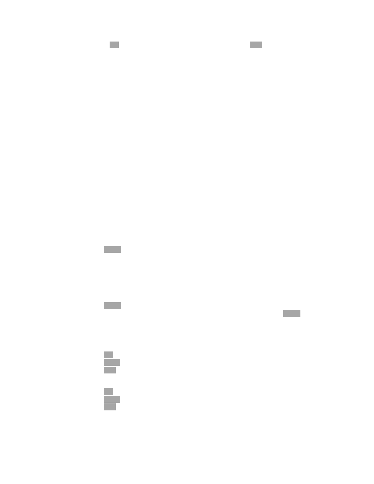
37
2) Press ON to set the level monitor function to ON. Press OFF to set the level
monitor function to off.
4.3.3.6 Deviation Measurement Function
The deviation measurement function allows you to display the deviation value instead
of the actual measurement value. The deviation value is the value calculated by
taking the difference between the actual measurement value and a previously stored
reference value. This function is useful when the change of a component's value
versus changes in temperature, frequency, bias, etc. are being observed. Deviation
measurements can be made for either or both primary parameter and/or secondary
parameter measurements. There are two types of deviation measurements.
ΔABS (Delta ABSolute) deviation measurement
The difference between the measured value of the DUT and a previously stored
reference value are displayed. The formula used to calculate the deviation is as
follows.
ΔABS = X-Y
Where, X: The measured value of DUT.
Y: The stored reference value.
Δ% (Delta percent) deviation measurement
The difference between the measured value of the DUT and a previously stored
reference value are displayed as a percentage of the reference value. The
formula used to calculate the percent deviation is as follows.
Δ% = (X-Y)/Y×100%
Where, X: The measured value of DUT.
Y: The stored reference value.
Perform the following steps to execute the deviation measurement function.
1) Move the cursor to the REF_A field to enter the reference value for the primary
parameter. The following softkey will be displayed.
MEAS
When the device which has a reference value is connected, pressing this
MEAS softkey, TH2816B measures the device, and the primary
measurement result is entered as a reference value for REF_A.
2) Enter the reference value for the primary parameter using MEAS or the numeric
entry keys.
3) Move the cursor to the REF_B field to enter the reference value for the secondary
parameter. The following softkey will be displayed.
MEAS
When the device is to be used as the reference value is connected, MEAS is
pressed, TH2816B measures the device, and the secondary measurement
result is entered as a reference value for REF_B values.
4) Enter the reference value for the secondary parameter using MEAS or the
numeric entry keys.
5) Move the cursor to the DEV_A field. The following softkeys will be displayed.
Δ%
ΔABS
OFF
6) Select and press a softkey to select the deviation mode for the primary parameter.
7) Move the cursor to the DEV_B field. The following softkeys will be displayed.
Δ%
ΔABS
OFF
8) Select and press a softkey to select the deviation mode for the secondary
parameter.
Page 38

38
4.3.3.7 File Management
This function is the same as the function on the MeasDisplay page. (Refer to 4.3.1.8
File Management.)
4.3.3.8 Useful Tools
The Tools field on this page allows you to reset all the control settings to the default
settings.
Perform the following steps from the Meas Setup page to reset all control settings.
1) Move the cursor to the Tools field. The following softkey will be displayed.
CLEAR
2) Press CLEAR, “Confirm: Clear All?” will be displayed in the message window.
The following softkeys will be displayed.
NO
YES
3) Press NO to cancel the CLEAR operation.
4) Press YES to reset all control settings to the default settings.
4.3.4 Limit Table
When you press PREVorNEXT, or LIMIT softkey, the Limit Table page will be
displayed. The Limit Table page allows you to set TH2816B's comparator.
TH2816B's built-in comparator can sort devices into a maximum of 10 bins (BIN1 to
BIN 9 and one OUT OF BINS) using a maximum of 3 pairs of primary limits and one
pair of secondary parameter limits. Also, devices whose primary parameter is within
limits, but whose secondary parameter measurement result is not within limits, can be
sorted into an AUXiliary BIN. The comparator function is especially useful when using
TH2816B with a component handler. These limit settings for bin sorting are only set
on this Limit Table page.
Nominal Value for tolerance mode (NOMINAL)
Measurement Function (FUNC)
Comparator Function's Limit Mode (MODE)
Comparator Function ON/OFF (COMP)
Auxiliary bin ON/OFF (AUX)
Low Limit Value of each bin (LOW)
High Limit Value of each bin (HIGH)
File Management (File)
Useful Tools (Tools)
Each function is described in the following paragraphs.
The available fields and the softkeys which correspond to the fields on this page are
shown in Figure 4-14 and Figure 4-15.
Page 39
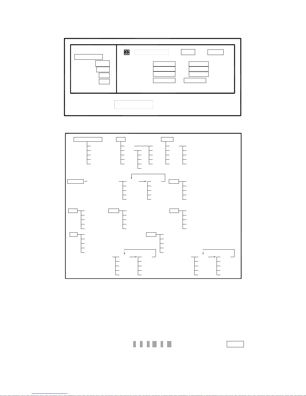
39
: Field
-0.090%
-0.070%
[ LOW ]
-0.050%
0.00010
LIMIT
FUNC: Cp-D
COMP: OFF
ALARM OFF
AUX: OFF
MODE: %TOL
NOMINAL:
217.259nF
3
2nd:
LIST
<Limit Table>
[BIN]
2
1
0.090%
0.00014
CORR SETUP
0.070%
0.050%
[ HIGH ]
ToolsFile
Figure 4-14. Available Fields on the Limit Table Page
LOW
MODE
NOMINAL
<Limit Table>
p
(TH2816A)
[NUMERIC ENTRY]
PAGE
DEL--
▼
▲
%TOL
±TOL
NEXT
μ
ESC
n
p
COMP
ON
OFF
μ
ESC
n
[NUMERIC ENTRY]
SETUP
CORR
LIMIT
LIST
NEXT
LOAD
SAVE
File
ESC
NEXT
m
DEL--
PAGE
[NUMERIC ENTRY]
HIGH
NEXT
ESC
k
M
m
ESC
M
k
(TH2816A)
▼
▲
n
μ
p
AUX
ON
OFF
SWAP
FUNC
CLEAR
Tools
NEXT
ESC
ESC
OK NO
YES
NEXT
ESC
k
M
m
Figure 4-15. Available Softkeys on the Limit Table Page
4.3.4.1 Nominal Value for tolerance mode
When the tolerance mode is used as a limit mode for the primary parameter, the
nominal value must be set.
Front Panel Operation for Setting the Nominal Value
Perform the following steps to set the nominal value.
1) Move the cursor to the NOMINAL field.
2) Enter the nominal value using the numeric entry keys. When the numeric data is
entered, the unit softkeys (p , n , μ, m , k , M ) can be used instead of ENTER.
Page 40

40
4.3.4.2 Swap Parameter Function
The swap parameter function is used to swap the primary parameter for the
secondary parameter in the FUNC field. For example, when the measurement
function is Cp-D, the swap parameter function sets the measurement function to
D-Cp. Then the comparison limits for D are a maximum of 3 pairs of comparison limits,
and the comparison limits for Cp are now one pair.
Front Panel Operation for Swapping Parameter Function.
Perform the following steps to swap the primary parameter for the secondary
parameter.
1) Move the cursor to the FUNC fied. The following softkey will be displayed.
SWAP
2) Press SWAP to swap the primary parameter for the secondary parameter.
3) Press SWAP again to return the measurement function to the previous
combination.
4.3.4.3 Comparator Function's Limit Mode
There are two methods used to specify the tolerance mode limits, the ratio in percent
and by parameter value.
Front Panel Operation for Setting the Limit Mode for the Comparator.
Perform the following steps to set the limit mode for the comparator.
1) Move the cursor to the MODE field. Then the following softkeys will be displayed.
% TOL
This softkey is used to set the limit mode to the tolerance mode (the ratio in
percent).
±TOL
This softkey is used to set the limit mode to the tolerance mode (parameter
value).
2) Select and set the limit mode using the softkeys.
4.3.4.4 Comparator Function ON/OFF
This function is the same as the function on the BinNo. Disp Page (Refer to 4.3.2.1
Comparator Function.)
4.3.4.5 Auxiliary bin ON/OFF
This function is the same as the function on the BinNo. Disp Page. (Refer to 4.3.2.2
Measurement Function.)
4.3.4.6 Low /High Limit Value
TH2816B's built-in comparator can sort devices into a maximum of 4 bins (BIN 1 to
BIN 3, and OUT OF BINS) using a maximum of 3 pairs of primary parameter limits
and one pair of secondary parameter limits. These primary parameter low/high limits
can be set in the BIN 1 to BIN 3 LOW/HIGH fields, and the secondary parameter
low/high limits can be set in the 2nd LOW/HIGH fields.
Note: Do NOT enter a value which is lower than the LOW limit into the HIGH limit.
If you do, the warning message “Warning: Low>High” will be displayed (this
isn't an error), and TH2816B will not sort a DUT into the warning BINs you
specify.
Front Panel Operation for Setting the Low/High Limits
Perform the following steps to set the bin sorting limits.
1) Set the measurement function for the comparator function, the nominal value,
Page 41

41
and the limit mode for the primary parameter.
2) Move the cursor to the Tools field, and perform the clear table function.
3) Move the cursor to the BIN 1 LOW field.
4) Enter the limit value of the BIN 1 at BIN 1 LOW field using the numeric entry keys.
When one of the numeric entry keys is pressed, the unit softkeys (p, n, μ, m, k,
and M) are available, and so you can use these softkeys to enter the unit and
terminate the entry without hitting ENTER. When the limit value of BIN 1 is
entered in the BIN 1 LOW field, the BIN 1 low limit becomes – (absolute input
value), and the BIN 1 high limit becomes + (absolute input value).
5) The cursor will be automatically moved to the BIN 2 LOW field. Repeat step 4
until the limits of the BIN 3 is entered. After that, the cursor will be moved to the
2nd LOW field.
6) Enter the low limit value of the secondary parameter. After that, the cursor will be
automatically moved to the 2nd HIGH field.
7) Enter the high limit value of the secondary parameter.
8) If you want to change one of the high or low limit value. Move the cursor to the
HIGH or LOW limit field, and input the new value using the numeric entry keys.
9) If you want to change both high and low limit values. Move the cursor to the
HIGH or LOW limit field, press DEL— softkey to clear both high and low limit
values. Then repeat step 4 to input the limits again.
4.3.4.7 File Management (File)
This function is the same as the function on the MeasDisplay page. (Refer to 4.3.1.8
File Management.)
4.3.4.8 Useful Tools
The Tools field on this page allows you to clear all of the limit values.
Perform the following steps from the Limit Table page to clear all of the limit values.
1) Move the cursor to the Tools field. The following softkey will be displayed.
CLEAR
2) Press CLEAR, “Confirm: Clear Table?” will be displayed in the message window.
The following softkeys will be displayed.
NO
YES
3) Press NO to cancel the CLEAR operation.
4) Press YES to clear all of the limit values.
4.3.5 System Configuration Page
When you press PREVorNEXT, or SYST softkey, the System Config page will be
displayed. On this System Config page, the following control functions can be set.
(The field in parenthesis is used to set the control function.)
LCD Contrast Function (CONTRAST)
Information Beeper Function ON/OFF (INFO BEEP)
Comparator Alarm Function ON/OFF (CMP ALARM)
Password Function (PASSWORD)
Bus Mode Function (BUS MODE)
GPIB address (GPIB ADDR)
AutoFetch mode ON/OFF (AUTO FETCH)
So there are eight fields on this page: <System Config>, CONTRAST, INFO BEEP,
CMP ALARM, PASSWORD, BUS MODE, GPIB ADDR, and AUTO FETCH fields.
Each control function is described in the following paragraphs.
The available fields and the softkeys which correspond to each field on this page are
shown in Figure 4-16 and Figure 4-17.
Page 42
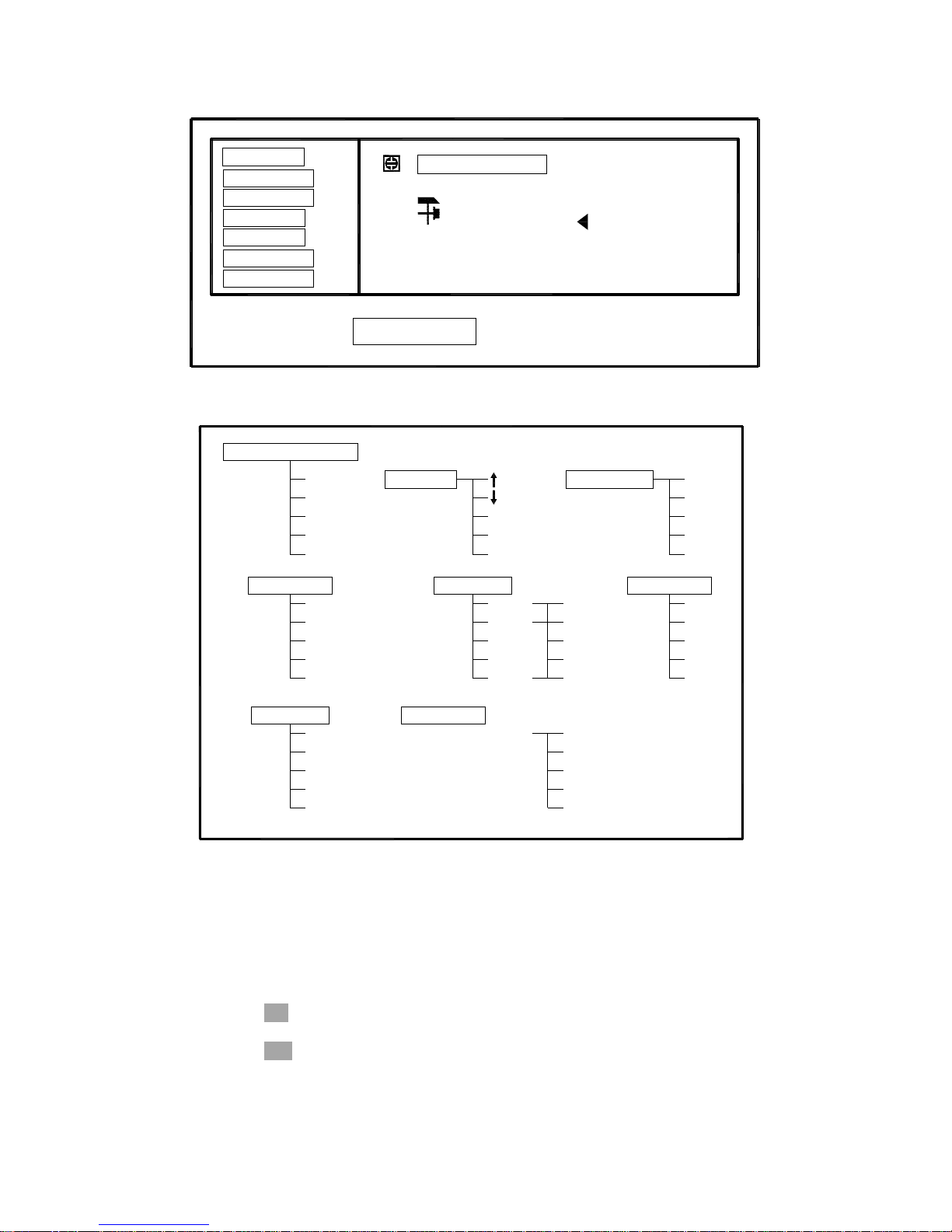
42
: Field
Left Colum
Select Item From
TEST
<System Config>
CONTRAST
INFO BEEP
CMP ALARM
PASSWORD
GPIB ADDR
TALK ONLY
BUS MODE
DEBUG FILE CFG
Figure 4-16. Available Fields on the SYSTEM CONFIG Page
[NUMERIC ENTRY]
GPIB ADDR
CONTRAST
BUS MODE
iBIAS
RS232
GPIB
FREQ3
FREQ2
FREQ1
CMP ALARM
<System Config>
DEBUG
CFG
FILE
TEST
INPO BEEP
NEW
ESC
ESC
OFF
UNLK
ALWAY
(-)
(+)
PASSWORD
TALK ONLY
OFF
ON
OFF
ON
Figure 4-17. Available Softkeys on the SYSTEM CONFIG Page
4.3.5.1 LCD Contrast Function
TH2816B’s Contrast Function allows you to adjust the LCD contrast in order to get a
clear display. You can adjust the LCD contrast from 0 to 31.
Perform the following steps to adjust the LCD contrast.
1) Move the cursor to the CONTRAST field, the following softkeys will be displayed.
↓(-)
This softkey is used to decrease LCD contrast in 1 step.
↑(+)
This softkey is used to increase LCD contrast in 1 step.
2) Use the softkeys to adjust the LCD Contrast as required.
Page 43
43
4.3.5.2 Information Beeper Function ON/OFF
TH2816B beeps when a warning message is displayed or an error has occurred.
Perform the following steps to set beeper function to ON or OFF.
1) Move the cursor to the INFO BEEP field, the following softkeys will be displayed.
ON
OFF
2) Use the softkeys to set the information beeper function to ON and OFF.
4.3.5.3 Comparator Alarm Function ON/OFF
TH2816B alarms when the comparator result is the same as the preset alarm status.
Perform the following steps to set the alarm status to be alarmed.
1) Move the cursor to the CMP ALARM field, the following softkeys will be
displayed.
AUX
OUT
IN
OFF
2) Use the softkeys to set the alarm status you want.
4.3.5.4 Password Function
TH2816B’s password function can be used to prevent unauthorized person to turn on
the instrument, or to prevent unauthorized person to operate from the front panel
keyboard.
Perform the following steps to set the password function or change the password.
1) Move the cursor to the PASSWORD field, the following softkeys will be
displayed.
NEW
ALWAY
UNLK
OFF
2) Press softkey NEW. Message “Old Password:” is displayed in the message
window. The old password is required to input correctly. Press the ESC softkey, if
you want to cancel the change password operation.
3) When the old password is inputted correctly, message “New Password:” is
displayed in the message window. Use the numeric entry keys to input the new
password. Press the ESC softkey, if you want to cancel the change password
operation.
4) When the new password is inputted, the message “Confirm Password:” is
displayed in the message window. Press the ESC softkey, if you want to cancel
the change password operation. The new password must be inputted correctly
again, before the new password is valid.
5) Press AWAY. The password is required both to turn on the TH2816B and to
unlock the key operation on front panel. “ALWAYS” will be displayed on the LCD.
6) Press UNLK. Message “Enter Password:” will be displayed, when you change
the password status from “AWAYS” to “UNLOCK”. When the password status is
“UNLOCK” status, the password is required only to unlock the key operation on
front panel.
7) Press OFF. Message “Enter Password:” will be displayed, when you change the
password status from “AWAYS”/“UNLOCK” to OFF. When the password status is
“OFF” status, no password is required both to turn on the instrument and to
unlock the key operation on front panel.
Note: The default password for TH2816B is 2816.
Page 44

44
4.3.5.5 Bus Mode Function
TH2816B provides three Bus modes: GPIB, RS232 and iBIAS. Only one of the three
bus modes can be selected at the same time.
Perform the following steps to select the bus mode of TH2816B.
1) Move the cursor to the BUS MODE field, the following softkeys will be displayed.
GPIB
RS232
iBIAS
2) Press iBIAS. The RS232 interface is used to control the programmable DC bias
current source. (Such as TH1773 )
3) Press RS232. The RS232 interface is used to communicate with a computer as a
standard serial interface.
4) Press GPIB. The GPIB interface is used to communicate with computers and
other instruments as a parallel interface. (When the optional GPIB board is
equipped.)
4.3.5.6 GPIB address
TH2816B with GPIB interface can be controlled via the GPIB bus.
The GPIB address can be set on this page
Perform the following steps to set the GPIB address.
1) Move the cursor to the GPIB ADDR field, the current address will be displayed
on the LCD. The default address is 8.
2) Input the new address from 0 to 30 using the numeric keys.
4.3.5.7 AutoFetch mode ON/OFF
When TH2816B is set to the auto fetch mode, TH2816B outputs the measurement
result after each measurement automatically.
Perform the following steps to set the Talk only mode.
1) Move the cursor to the Auto Fetch field, the current setting will be displayed on
the LCD. The following softkeys will also be displayed.
ON
OFF
2) Use the softkeys to set the Auto Fetch mode to ON (Auto fetch) or to OFF (query
mode).
Page 45
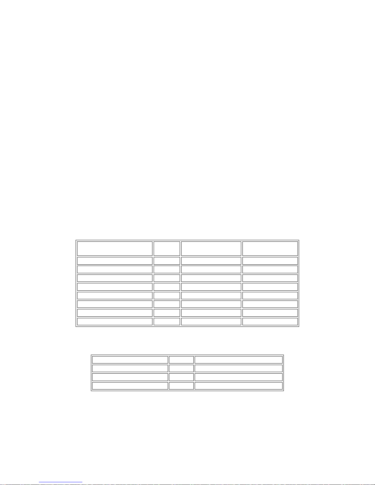
45
Chapter 5 Remote Control
TH2816B has the RS232C serial interface and the parallel GPIB (optional) interface.
Both interfaces can be used to remotely control TH2816B, but they can not be used
at the same time. The two interfaces share the same program commands, but they
have different hardware configurations and different communication protocols. This
chapter provides the information about the two interfaces and how to use the
interfaces. For the available commands, refer to Chapter 6 Command reference.
5.1 RS232C Interface Introduction
The RS232C interface can be used to remotely control the TH2816B, and it also can
be used to control the DC current bias sources manufactured by our company such
as TH1773/TH1775 DC current bias source. All operations from the front panel can
be performed by a computer via the serial interface.
5.1.1 RS232C Connection
RS232C Standard now is widely used as the serial communication standard. RS232
stands for Recommend Standard number 232 and C is the latest revision of the
standard. The serial ports on most instruments use a subset of the RS-232C standard.
The full RS-232C standard specifies a 25-pin "D" connector of which 22 pins are used.
Most of these pins are not needed for normal serial communications, and the
common RS232 signals are listed as follows.
TH2816B only uses the smallest subset of the RS232C standard, the signal are listed
as follows.
Function Code 9 Pin Connector Pin Number
Transmitted Data TXD 3
Received Data RXD 2
Signal Ground Common GND 5
TH2816B’s RS232 interface may be different with the standard RS232C. The pin
configuration is shown as follows.
Function Code
25 Pin Connector
Pin Number
9 Pin Connector
Pin Number
Request To Send RTS 4 7
Clear To Send CTS 5 8
Data Set Ready DSR 6 6
Data Carrier Detect DCD 8 1
Data Terminal Ready DTR 20 4
Transmitted Data TXD 3 3
Received Data RXD 2 2
Signal Ground Common GND 7 5
Page 46
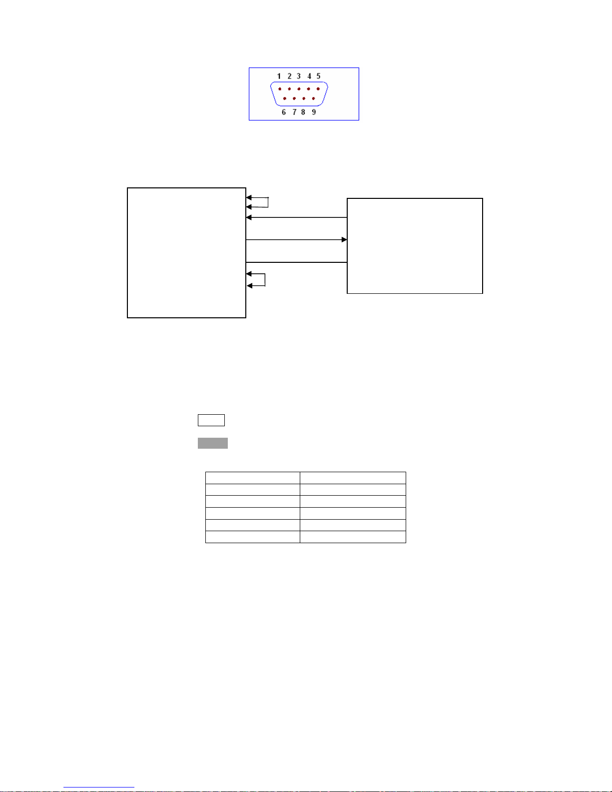
46
5.1.2 Communication with a Computer
Diagram of connection to a controller.
DTR (4)
DSR (6)
RXD (2) (3) TXD
Computer
(Controller) TXD (3) (2) RXD TH2816B
GND (5) (5) GND
RTS (7)
CTS (8)
There may be some difference between TH2816B RS232 interface and a
standard RS232C interface. You can make the connection cable by yourself
according the diagram or order one from our company.
Note: Pin 4 and 6, pin 7 and 8 are shorted respectively at the end of controller.
When the RS232C interface is used to communicate with a controller, RS232
bus mode should be selected as follows.
1) Press NEXT menu key, until the System Config page be displayed.
2) Move the cursor to the BusMode field.
3) Press RS232 to select the bus mode to RS232 bus mode.
Serial Interface Specifications
Baud Rate 9600 bps
Date Bits 8 Bits
Stop Bits 1 Bit
Parity Bit None
End of Sequence NL (ASCII Code 10)
Connector DB9
Software Protocol
1) For command configuration and format, refer to chapter 6 Command
Reference.
2) The controller sends the command using the ASCII code with NL as the end
character. TH2816B executes the command after the end character NL is
received.
3) The character received by TH2816B will be sent back to the controller again.
The controller will not send the next character until the last return character
is received correctively from TH2816B. If the controller cannot receive the
character sent back by TH2816B, the reasons may be as follows.
A. The serial interface is not connected correctly.
B. Check if the RS232 function is turned on and TALK ONLY function is
turned off.
C. When TH2816B is executing a bus command, TH2816B will not accept
any character through the serial interface at the same time and the
Page 47

47
character sent by controller will be ignored. In order to make sure the
whole command is sent and received correctly, the character without a
return character should be sent again by the controller.
4) TH2816B sends information under following two conditions. The first is when
a character is received normally; TH2816B will send the character back as
response. The second is when a query command is received; TH2816B will
send the query response information.
5) Once a query command is received, TH2816B will send the query response
information immediately even if the whole command has not been executed.
So if the command includes two queries, the controller should read the
query responses twice. One query is recommended to be included in a
single command.
6) A query response is sent out in ASCII codes with NL as the terminal
character.
7) Several query responses will be sent continuously with 1ms interval. The
controller should be ready to receive the responses; otherwise the response
information will be lost.
8) The controller should receive the query response terminal character NL.
Otherwise you will confuse a terminal character NL with a returned character.
At the same time the controller should receive the last returned character
before receiving a query response.
9) For some commands that will take a long time to execute, for example
Correction command, the controller should keep waiting to avoid the next
command being lost when TH2816B is executing the former command.
Sample Program for Serial Interface
The following is a C language sample program under DOS environment. The
main function may be expanded by users, and the other sub functions teach you
how to input or output a character string via the RS232 interface.
#define PORT 0
#include "dos.h"
#include "stdio.h"
#include "stdlib.h"
#include "ctype.h"
#include "conio.h"
void port_init( int port,unsigned char code );
int check_stat( int port ); /* read serial port state(16bit) */
void send_port( int port,char c ); /* send a character to serial port */
char read_port( int port ); /* recive a character form serial port */
void string_wr( char *ps ); /* write a string to serial port */
void string_rd( char *ps ); /* read a string from serial port */
char input[256]; /* quary recieve bufer */
main()
{ port_init( PORT,0xe3 );/* initilize serial port:baud = 9600,no verify,1 bit stop,8 bit
data */
string_wr( "trig:sour bus;*trg" );
string_rd( input );
printf( "\n%s",input );
string_wr( "freq 10khz" );
string_wr( "func:imp:type rx;:func:smon on" );
string_wr( "voltage:level 500mv" );
Page 48

48
}
/* write string to serial port */
void string_wr( char *ps )
{ char c;
int m,n;
while( check_stat(PORT) & 256 ) read_port( PORT );/* read data until null */
for( ;*ps; )
{ c = 0;
for( m = 100;m;m-- )
{ send_port( PORT,*ps );
for( n = 1000;n;n-- )
{ delay( 2 ); /* wait about 2ms, use dos.h libray funtion */
if( kbhit() && ( getch() == 27 ) ) /* if escape key keypress */
{ printf( "\nE20:Write Canceled!" );
exit(1);
}
if( check_stat(PORT) & 256 )
{ c = read_port( PORT );
break;
}
}
if( n ) break;
}
if( c == *ps ) ps++;
else
{ printf( "\nE10:Write Echo Error!" );
exit(1);
}
}
send_port( PORT,'\n' );/* send command end symbol */
delay( 2 );
while( !(check_stat(PORT) & 256) );
read_port( PORT );
}
/* read string from serial port */
void string_rd( char *ps )
{ unsigned char c,i;
for( i = 0;i < 255;i++ ) /* max read 256 characters */
{ while( ! (check_stat(PORT) & 256) ) /* wait serial recieve ready */
if( kbhit() && (getch() == 27) ) /* if escape key keypress */
{ printf( "\nE21:Read Canceled!" );
exit(1);
}
c = read_port( PORT );
if( c == '\n' ) break;
*ps = c;
ps++;
}
*ps = 0;
}
/* send a character to serial port */
void send_port( int port,char c )
Page 49
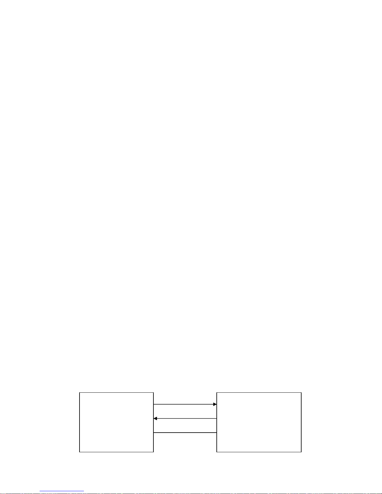
49
{
union REGS r;
r.x.dx = port; /* serial port */
r.h.ah = 1; /* int14 function1:send character */
r.h.al = c; /* character to be sent */
int86( 0x14,&r,&r );
if( r.h.ah & 128 ) /* check ah.7,if set by int86( 0x14,&r,&r ),mean trans error */
{ printf( "\nE00:Serial port send error!" );
exit(1);
}
}
/* read a character from serial port */
char read_port( int port )
{ union REGS r;
r.x.dx = port; /* serial port */
r.h.ah = 2; /* int14 function2:read character */
int86( 0x14,&r,&r );
if( r.h.ah & 128 ) /* if ah.7 be set,mean trans error */
{ printf( "\nE01:Serial port read error!" );
exit(1);
}
return r.h.al;
}
/* check the status of serial port */
int check_stat( int port )
{ union REGS r;
r.x.dx = port; /* serial port */
r.h.ah = 3; /* int14 function3:read status */
int86( 0x14,&r,&r );
return r.x.ax; /* ax.7 show serial operation, ax.8 show serial recive ready
*/
}
/* initialize the serial port */
void port_init( int port,unsigned char code )
{ union REGS r;
r.x.dx = port; /* serial port */
r.h.ah = 0; /* int14 function0:initial serial port */
r.h.al = code; /* initialization code */
int86( 0x14,&r,&r );
}
5.1.3 Communication with a DC Bias Current Source
When you want to perform a DC bias current list sweep measurement, the RS232C
can be used to control a DC Bias Current Source. The following diagram shows how
TH2816B and TH1773 are connected via the RS232C interface.
TXD(2) (3) RXD
TH2816B TH1773
LCR Meter RXD(3) (2) TXD DC Bias Current
Source
GND(5) (5) GND
Page 50

50
Perform the following steps to realize the DC bias current list sweep measurement.
1) Only on the List Sweep page, TH2816B has the capacity to control the DC Bias
Current Source via the RS232C interface.
2) Connect TH2816B and TH1773 according the above diagram.
3) Set TH2816B’s bus mode to iBIAS mode. Press SYSTEM menu key, the System
Config page will be displayed. Move the cursor to the BusMode field, and use
the softkey iBIAS to set the bus mode to iBIAS mode.
4) Set TH1773’s serial function to ByLCR mode (Refer to TH1773 user manual.).
5) Set a list sweep measurement limit table on the List Setup page, and perform the
measurements on the List Sweep page.
When perform the DC bias current list sweep measurement, delay time should be set
in order to get stable measurement results.
SEQ or STEP sweep mode can be selected.
5.2 GPIB Interface Introduction
5.2.1 GPIB Connection
When configuring a GPIB system, the following restrictions must be adhered to.
The total length of cable in one bus system must be less than or equal to two
meters times the number of devices connected on the bus (the GPIB controller
counts as one device) and the total length of cable must not exceed 20 meters.
A maximum of 15 devices can be connected on one bus system.
There are no restrictions on how the cables are connected together. However, it
is recommended that no more than four piggyback connectors be stacked
together on any one device. The resulting structure could exert enough force on
the connector mounting to damage it.
Figure 5-1 shows a GPIB interface connector.
Page 51
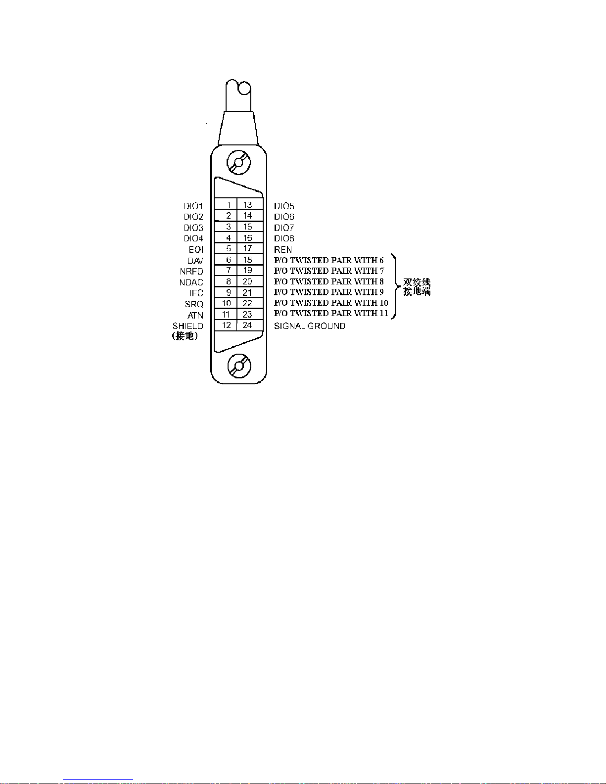
51
Figure 5-1. GPIB Connector Signal/Pin Configuration
Typical GPIB system interconnection is shown in Figure 5-2 and Figure 5-3. The GPIB
connector is firmly fastened using two bolts to keep it from working loose during use.
Page 52
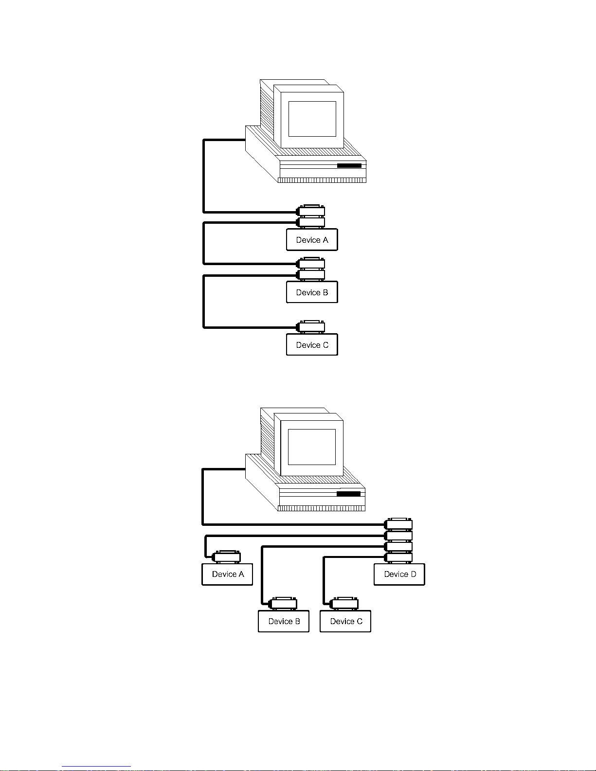
52
Figure 5-2. Typical GPIB System Interconnection-1
Figure 5-3. Typical GPIB System Interconnection-2
Page 53
53
5.2.2 GPIB Interface Capabilities Functions
Table 7-1 lists TH2816B's GPIB capabilities and functions. These functions provide
the means for an instrument to receive, process, and transmit commands, data, and
status over the GPIB bus.
Table 7-2. GPIB Interface Capability
Code
Function
SH1
Complete Source Handshake capability
AH1
Complete Acceptor Handshake capability
T5
Basic Talker; Talk-Only; unaddressed if MLA; no serial poll
L4
Basic Listener; unaddressed if MTA; no Listen Only
SR0
No Service Request capability
RL1
Remote/Local capability
DC1
Device Clear capability
DT1
Device Trigger capability
C0
No Controller capability
E1
Drivers are open-collector
5.2.3 GPIB Addressing
TH2816B's GPIB address is stored in non-volatile memory and can be set to any
address from 0 to 30 by front panel key entry in the System Config page. When
TH2816B is shipped from the factory the default GPIB address is 8. For more
information, refer to “ 4.4.1.6 GPIB Address” in Chapter 4.
5.2.4 GPIB Bus Function
TH2816B will respond to the following bus commands.
ABORT I/O (IFC)
ABORT I/O (IFC control line TRUE) halts all bus activity and deselects TH2816B.
DEVICE CLEAR (SDC or DCL)
This command can be used with an address to clear a particular device (SDC :
selected device clear) or used without an address (DCL : clears all devices). The
Input buffer is cleared, output data buffer is cleared and bit 4 (MAV bit) of the
status byte is set to “0”, when TH2816B receives this command.
LOCAL (GTL)
LOCAL returns control of a listening device to front panel control.
LOCAL LOCKOUT (LLO)
LOCAL LOCKOUT disables the LOCAL operation of all devices on the bus. After
this command is sent you will be unable to operate TH2816B from the front panel
include the softkey LOCAL. Execute the LOCAL command to undo LOCAL
LOCKOUT.
REMOTE
REMOTE sets TH2816B to the remote mode. When this command is sent, front
panel with the exception of LOCAL softkey will be disabled.
TRIGGER (GET)
Enables TH2816B to the TRIGGER bus command. This command may be sent
to a selected device or to all devices addressed as listeners on the GPIB bus.
TH2816B must first be addressed as a listener, second the trigger mode is set to
the BUS trigger mode before the trigger message is sent. This command is equal
to the SCPI command TRIG+FETCh? or the common command *TRG.
5.3 Data Format
Th2817 outputs the measurement results using the ASCII via the GPIB bus. The
Format 1 is used by MeasDisplay page, BinNo. Disp page and Bin Count page,
Page 54
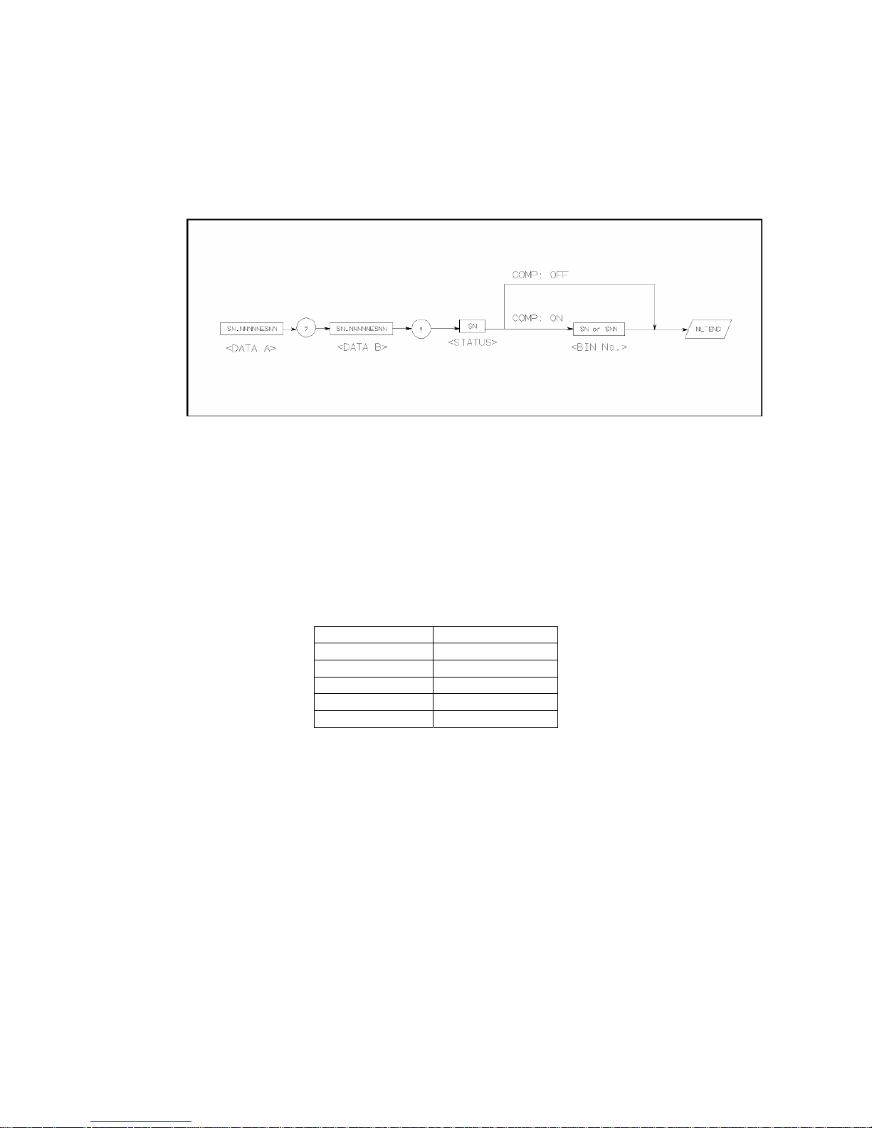
54
while Format 2 is used by List Sweep page. The two formats are described
respectively as follows.
5.3.1 Format 1
The ASCII data output format on the MeasDisplay page, BinNo. Disp page, or Bin
Count page is described in Figure 5-4.
Figure 5-4 ASCII Data Format 1
The <DATA A>, <DATA B>, and <BIN> formats are as follows.
<DATA A> and <DATA B> format:
The data output formats for <DATA A> (primary parameter's measurement data), and
<DATA B> (secondary parameter's measurement data) uses the 12 ASCII character
fixed length format as follows.
SN.NNNNNESNN
(S: +/-, N: 0 to 9, E: Exponent Sign)
<BIN> Format:
The <BIN No.> data shows the bin sorting results as follows.
Data Sorting Results
1 BIN 1
2 BIN 2
3 BIN 3
4 AUX_BIN
5 OUT_OF_BINS
The <BIN No.> data is output with the measurement data only when the
comparator function is set to ON.
Page 55
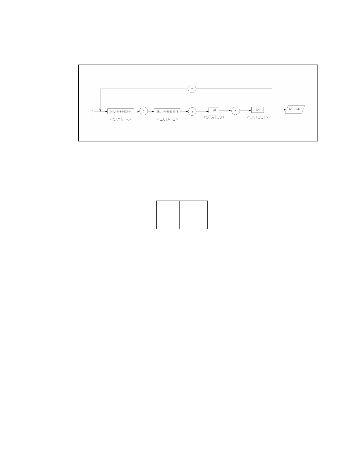
55
5.3.2 Format 2
The ASCII data output format on the List Sweep page is described in Figure 5-5.
Figure 5-5 ASCII Data Format 2
The data loop is repeated for the number of the sweep points.
The <DATA A>, <DATA B>, <STATUS> formats are the same as the formats on the
MeasDisplay, Bin No. Disp, or Bin Count page. So the only the <IN/OUT> format
will be described.
<IN/OUT> format:
The <IN/OUT> data shows the result of the list sweep's comparator function.
When the comparator function for the list sweep measurement isn’t used, the
<IN/OUT> use the 2 ASCII character fixed length format as follows.
SN (S:+/-, N: 0 to 1)
Data Result
-1 OUT
0 IN
+1 HIGH
Page 56

56
Chapter 6 Command Reference
This chapter provides descriptions of all TH2816B's available GPIB commands which
correspond to Standard Commands for Programmable Instruments (SCPI) command
sets, listed in functional subsystem order. Use this chapter as a reference.
6.1 Notation Conventions and Definitions
The following characters are used in the command syntax.
: A colon is used to separate the higher level commands and the lower level
commands.
; The semicolon can be used as a separator to execute multiple commands
on a single line.
* Asterisk is used to indicate that the command followed is a common
command.
? A question mark is used to generate a query for the command in front of it.
, Comma is used to separate the muti-parameters in the command.
White space is used to separate the command and the parameter.
“” Double quotation marks indicate that the enclosed test is string data.
The following characters will be used in this chapter to describe GPIB commands.
NR1 Integer numeric data
NR2 fixed point numeric data
NR3 floating point numeric data
NL New Line character (decimal 10) is the end of the input/output string.
^END EOI terminator signal
< > Angular brackets enclose words or characters that are used to symbolize a
program code parameter or a GPIB command.
[ ] Square brackets indicate that the enclosed items are optional. The square
brackets with the asterisk (for example, [,<value>* ]) means the enclosed
item (<value>) repeats until the maximum counted number.
{} When several items are enclosed by braces, one and only one of these
elements may be selected.
6.2 Command Structure
TH2816B commands are divided into two types: GPIB common commands and SCPI
commands. The GPIB common commands are defined in IEEE std. 488.2-1987, and
these commands are common for all devices. The SCPI commands are used to
control all of the TH2816B's functions. The SCPI commands are tree structured three
levels deep. (The highest level commands are called the subsystem commands in
this manual.) So the lower level commands are legal only when the subsystem
commands have been selected. A colon (:) is used to separate the higher level
commands and the lower level commands. See Figure 6-1 for a sample.
Page 57
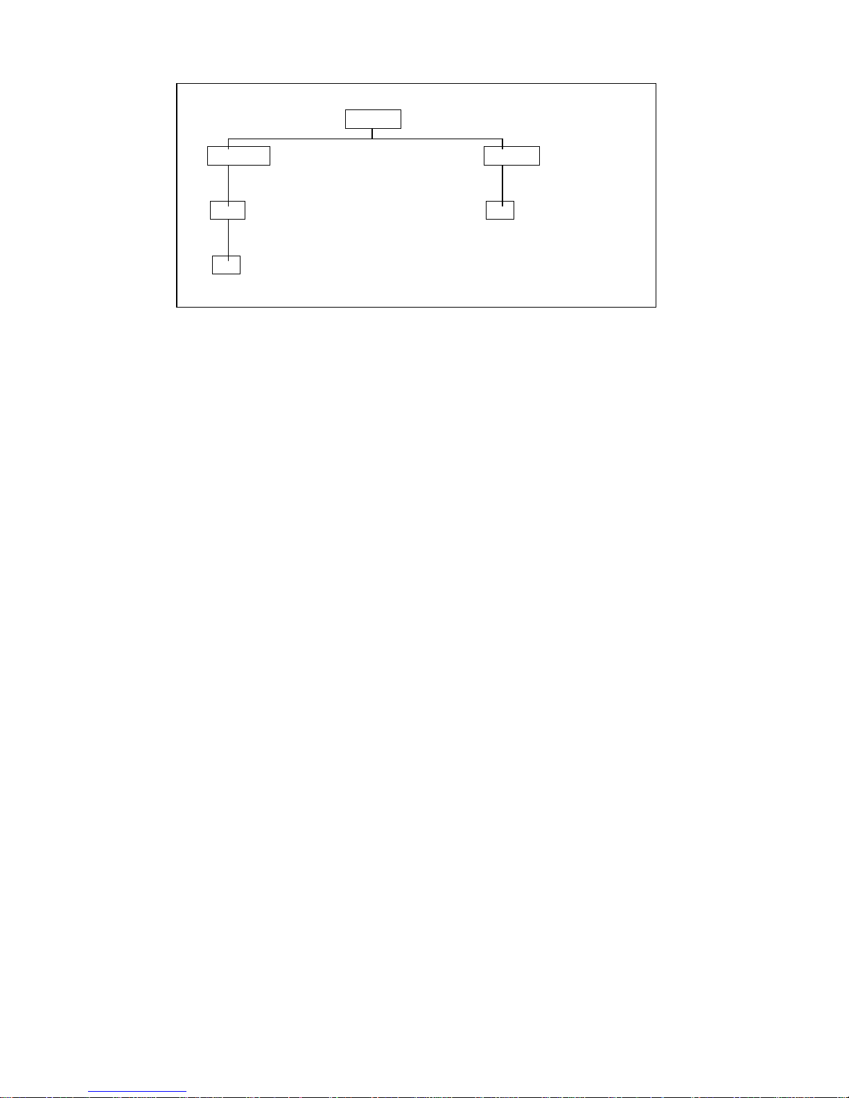
57
FUNCtion
IMPedence SMONitor
FUNC:IMP CPD
RANGe VIAC
FUNC:IMP:RANG 1k FUNC:SMON:STAT ON
AUTO
FUNC:IMP:RANG:AUTO ON
Figure 6-1. Command Tree Example
The basic rules of the command tree are as follows.
Letter case (upper and lower) is ignored.
For example,
FUNC:IMP CPD = func:imp cpd = Func:Imp CpD
Spaces (
︺
is used to indicate a space) must not be placed before and/or after
the colon (:).
For example,
(wrong) FUNC
︺:︺
IMP CPD
(right) FUNC:IMP CPD
The command can be completely spelled out or in abbreviated type.
(The rules for command abbreviation are described later in this section)
For example,
FUNCTION:IMPEDANCE CPD = FUNC:IMP CPD
The command header should be followed by a question mark (?) to generate a
query for that command.
For example,
FUNC:IMP?
The semicolon (;) can be used as a separator to execute multiple commands on a
single line. The multiple command rules are as follows.
Commands at the same level and in the same subsystem command group can
be separated by a semicolon (;) on a multiple command line.
For example,
CORR:SPOT1:STAT ON;FREQ 1KHZ
To restart commands from the highest level, a semicolon (;) must be used as the
separator, and then a leading colon (:), which shows that the restarted command
is a command at the top of the command tree, must follow.
For example,
FUNC:IMP CPD;:FUNC:SMON:STAT ON
The GPIB common commands can restart only after a semicolon on a multiple
command line.
For example,
FUNC:IMP CPD;*trg;SMON ON
The GPIB common commands keeps the previous commands level in a multiple
command line.
For example,
FUNC:IMP CPD;*SRE 32;SMON:VAC ON;IAC ON
Page 58

58
6.3 Command Abbreviations
Every command and character parameter has at least two forms, a short form and a
long form. In some cases they will be the same. The short form is obtained using the
following rules.
If the long form has four characters or less, the long form and short form are the
same.
If the long form has more than 4 characters, and if the 4th character is a vowel,
the short form is the first 3 characters of the long form. If the 4th character is not
a vowel, the short form is the first 4 characters.
For example:
MODE abbreviates to MODE.
TRIGger abbreviates to TRIG.
LEVel abbreviates to LEV.
FREQuency abbreviates to FREQ.
If the long form mnemonic is defined as a phrase rather than a single word, then
the long form mnemonic is the first character of the first word(s) followed by the
entire last word. The above rules, when the long form mnemonic is a single word,
are then applied to the resulting long form mnemonic to obtain the short form.
For example:
Percent TOLerance abbreviates to PTOL. (The long form is PTOLerance.)
Note: TH2816B accepts the three forms of the same SCPI commands: all upper case,
all lower case, and mixed upper and lower case.
6.4 Suffix Units and suffix Multipliers
When numeric data is used as a parameter, the suffix multiplier mnemonics and suffix
units (The suffix multiplier must be used with the suffix unit.) can be used for some
commands as follows.
Table 6-1. Multiplier Mnemonics
Denition Mnemonic Used by TH2816B
1E18 (EXA) EX NO
1E15 (PETA) PE NO
1E12 (TERA) T NO
1E9 (GIGA) G NO
1E6 (MEGA) MA YES
1E3 (KILO) K YES
1E-3 (MILI) M YES
1E-6 (MICRO) U YES
1E-9 (NANO) N YES
1E-12 (PICO) P YES
1E-15 (FEMTO) F NO
1E-18 (ATTO) A NO
M or MA is available only when the suffix unit is HZ.
Page 59
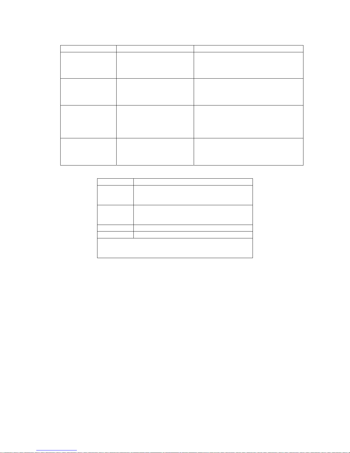
59
Table 6-2. Suffix Multipliers without Suffix Units
Type of Command Available Command Example
Deviation reference
value
FUNC:DEV1:REF
FUNC:DEV2:REF
:REF 100p
If the measurement function is Cp-D, then
deviation reference value for primary
parameter is 100pF
Standard value for
load correction
CORR:SPOTn:LOAD:STAN :STAN 0.1k,-12
If the measurement function for load
correction is R-X, then standard value for
load correction is 100Ωand -12Ω.
Limit value for list
sweep
LIST:BANDn :BAND1 A,100u,110u
If the measurement function for list sweep
measurement is L-Q, then the low limit for
primary parameter is 100uH, and the high
limit for primary parameter is 110uH.
Limit value for
comparator
COMP:TOL:NOM
COMP:TOL:BINn
COMP:TOL:SLIM
:NOM 100m
If the swapped measurement function for
comparator is Cs-Rs, then the nominal
value for Rs is 100mΩ.
Table 6-3. Suffix Units and Available Commands
Suffix Unit Available Command
HZ
FREQ
LIST:FREQ
CORR:SPOTn:FREQ
V, mV
VOLT
VOLT:LEV
LIST:VOLT
A, mA, uA LIST:BIAS
s,ms TRIG:DEL
For TH2816B, only the fixed frequency value and unit
configurations can be used. Refer to the FREQ subsystem
commands.
6.5 Command Reference
All commands in this reference are fully explained and listed in the following
functional command order.
TH2816B Subsystem Commands
◇ DISPlay ◇ FREQuency ◇ VOLTage ◇ FUNCtion
◇ APERture ◇ TRIGger ◇ FETCh?
◇ ABORt ◇ CORRection ◇ COMParator ◇ Mass MEMory
GPIB Common Commands
◇ *RST ◇ *TRG ◇ *IDN
The explanation of each subsystem command is patterned as follows.
1) Subsystem command name
2) Command Tree (Subsystem command only)
3) Compound Command Name
4) Command Description
5) Command Syntax
6) Example Using The Above Command Syntax
7) Query Syntax
8) Query Response
9) Example Using The Above Query Syntax
Page 60

60
6.5.1 DISPlay Subsystem
The DISPlay subsystem command group sets the display page. Figure 6-2 shows the
command tree of the DISPlay subsystem command group.
DISPlay :PAGE
MEASurement
BNUMber
MSETup
LTABle
SYSTem
:DOWN ON (1)
OFF (0)
Figure 6-2. Display Subsystem Command Tree
:PAGE
The :PAGE command sets the display page. The :PAGE? Query returns the
abbreviated page name currently displayed on the LCD screen.
Command Syntax
DISPlay:PAGE <page name>
Where, <page name> is:
MEASurement Sets display page to MeasDisplay
BNUMber Sets display page to BinNo. Disp
MSETup Sets display page to Meas Setup
LTABle Sets display page to Limit Table
SYSTem Sets display page to System Config
Example
WrtCmd(“DISP:PAGE MEAS”) Set display page to the MeasDisplay page.
Query Syntax
DISPlay:PAGE?
Query Response
Returned data format is :
<page name><NL^END>
Where,
<page name> Return the abbreviated name of the current display page as shown in
the preceding list.
:DOWN
The :PAGE command sets the display character size of the measurement results.
The :PAGE? Query returns the status of the display character size of the
measurement results.
Command Syntax
ON
DISPlay:DOWN OFF
1
0
Where,
1 (decimal 49) When the function is ON, normal character size is displayed.
0 (decimal 48) When the function is OFF, large character size is displayed.
Page 61

61
Example
WrtCmd(“DISP:DOWN 1”) Set display character to normal size.
Query Syntax
DISPlay:DOWN?
Query Response
Returned data format is :
<NR1><NL^END>
6.5.2 FREQuency Subsystem
The FREQuency command sets the oscillator frequency. The FREQuency? query
returns the current test frequency setting.
Command Syntax
<value>
FREQuency MIN
MAX
Where,
<value> The available values are listed as follows
50, 60,
100, 120, 200, 400, 500,
1000, 2000, 4000, 5000,
10000, 20000, 40000, 50000
100000,
50hz, 60hz,
100hz, 120hz, 200hz, 400hz, 500hz,
1khz, 2khz, 4khz, 5khz,
10khz, 20khz, 40khz, 50khz,
100khz
MIN Sets to the minimum value (50 Hz)
MAX Sets to the maximum value (100 kHz)
Example
WrtCmd (“FREQ 1KHZ”) Set test frequency to 1000 Hz
Note: When frequency list sweep measurement is sweeping, you cannot use this
command to set the frequency. If you do so, “Cannot Executed” will be
displayed in the message window.
Query Syntax
FREQuency?
Query Response
Returned Format is :
<NR1><NL^END>
Page 62
62
6.5.3 VOLTage Subsystem
The VOLTage command sets the oscillator's output voltage level and output
impedance. The VOLTage? query returns the current oscillator voltage level. Figure
6-3 shows the VOLTage Subsystem Command Tree.
VOLTage [:LEVel] <value>
MIN
MAX
:SRESistance 30ohm
100ohm
Figure 6-3 VOLTage Subsystem Command Tree
Command Syntax
<value>
VOLTage[:LEVel] MIN
MAX
Where,
<value> is the NR1, NR2, or NR3 format followed by V or mV, the value must be
from 10 mV to 2 V.
MIN Sets or returns to the minimum oscillator voltage level (10 mV)
MAX Sets or returns to the maximum oscillator voltage level (2 V)
Example
WrtCmd(“VOLT 1V) Set oscillator voltage level to 1 V.
Note: When oscillator voltage level list sweep measurement is sweeping, you
cannot use this command to set the oscillator voltage level. If you do so,
“Cannot Executed” will be displayed in the message window.
Query Syntax
VOLTage? or VOLTage:LEVel?
Query Response
Returned format is :
<NR3><NL^END>
:SRESistance
:SRESistance is used to set the signal source output resistance.
Command Syntax
30 ohm
VOLTage:SRESistance
100 ohm
Example
WrtCmd(“VOLT:SRES 30 ohm”) Set signal source output resistance to 30 ohm.
Query Syntax
There is no query command for signal source output resistance function.
Page 63
63
6.5.4 FUNCtion Subsystem
The FUNCtion subsystem command group sets the measurement function, the
measurement range, monitor ON/OFF control, and the deviation measurement
control. Figure 6-4 shows the command tree of the FUNCtion subsystem command
group.
FUNCtion :IMPedance [:TYPE] CPD
CPRP
CSD
CSRS
LSQ
LSRS
LPQ
LPRP
ZTD
ZTR
RX
:RANGe <value>
:AUTO ON (1)
OFF (0)
:DEV1 :MODE ABSolute
2 PERcent
OFF
:REFerence <value>
:FILL
Figure 6-4. FUNCtion Subsystem Command Tree
:IMPedance
The :IMPedance command sets the measurement function. The :IMPedance? query
returns the current measurement function.
Command Syntax
FUNCtion:IMPedance <function>
Where, <function> is:
CPD Sets function to Cp-D LPQ Sets function to Lp-Q
CPRP Sets function to Cp-Rp LPRP Sets function to Lp-Rp
CSD Sets function to Cs-D ZTD Sets function to Z-θ (deg)
CSRS Sets function to Cs-Rs RX Sets function to R-X
LSQ Sets function to Ls-Q ZTR Sets function to Z-θ (rad)
LSRS Sets function to Ls-Rs
Example
Page 64

64
WrtCmd(“FUNC:IMP RX) Set the measurement function to R-X.
Query Syntax
FUNCtion:IMPedance?
Query Response
Returned format is:
<function><NL^END>
:IMPedance:RANGe
The :IMPedance:RANGe command sets the measurement range.
The :IMPedance:RANGe? query returns the current measurement range even if the
measurement range is set to AUTO.
Command Syntax
FUNCtion:IMPedance:RANGe <value>
Where, <value> is in the NR1 format with a suffix multiplier and a suffix unit. OHM,
and KOHM can be used with this command. The values can be used with this
command are listed as follows.
10, 30, 100, 300, 1000, 3000, 10000, 30000, 100000
or 10ohm, 30ohm, 100ohm, 300ohm, 1kohm, 3kohm, 10kohm, 30kohm,
100kohm
If values other than preceding values are used, “Error Parameter” will be displayed in
the message window.
Example
WrtCmd(“FUNC:IMP:RANG 1KOHM”) Set the measurement range to 1Kohm.
If this command is received while auto range is ON, the auto range function is
automatically set to OFF and the range will be held at the range dictated by the
received command.
Query Syntax
FUNCtion:IMPedance:RANGe?
Query Response
Returned format is:
<value><NL^END>
Where, <value> is 10, 30, 100, 300, 1000, 3000, 10000, 30000, 100000
:IMPedance:RANGe:AUTO
The :IMPedance:RANGe:AUTO command sets the auto range to ON or OFF.
The :IMPedance:RANGe:AUTO? query returns the current auto range ON/OFF
condition.
Command Syntax
ON
FUNCtion:IMPedance:RANGe:AUTO OFF
1
0
Where,
1 (decimal 49) When the function is ON
0 (decimal 48) When the function is OFF
Page 65

65
Example
WrtCmd(“FUNC:IMP:RANG:AUTO ON ”) Set the measurement range to AUTO.
Query Syntax
FUNCtion:IMPedance:RANGe:AUTO?
Query Response
Returned format is :
<NR1><NL^END>
:DEV<n>:MODE
The :DEV<n>:MODE command sets the deviation measurement mode.
The :DEV<n>:MODE? query returns the current setting of the deviation measurement
mode.
Command Syntax
ABSolute
FUNCtion:DEC<n>:MODE PERCent
OFF
Where,
ABSolute ΔABSolute deviation mode
PERCent Δ% deviation mode
OFF Turn the deviation measurement mode OFF
<n> is:
1 (decimal 49) Deviation mode setting for primary parameter
2 (decimal 50) Deviation mode setting for secondary parameter
Example
WrtCmd(“FUNC:DEV1:MODE ABS”)
Set ΔABSolute deviation mode for the primary parameter.
Query Syntax
FUNCtion:DEV<n>:MODE?
Query Response
Returned format is :
ABS
PER <NL^END>
OFF
:DEV<n>:REFerence
The :DEV<n>:REFerence command sets the reference value for deviation
measurement. The :DEV<n>:REFerence? query returns the current reference values.
Command Syntax
FUNCtion:DEV<n>:REFerence<value>
Where,
<value> is the NR1, NR2, or NR3 format with a suffix multiplier ma, k, m, u, n, p.
<n> is:
1 (decimal 49) Reference value setting for primary parameter
2 (decimal 50) Reference value setting for secondary parameter
Example
WrtCmd(“FUNC:DEV1:REF 10”)
Page 66

66
The <value> may be used without a suffix unit; the unit has been defined by the
current measurement function.
Query Syntax
FUNCtion:DEV<n>:REFerence?
Query Response
Returned format is :
<NR3><NL^END>
:REFerence:FILL
The :DEV<n>:REFerence:FILL command executes a single measurement and enters
two measured values (the primary and secondary parameters) into each of the
reference values for the deviation measurement.
Command Syntax
FUNCtion:DEV<n>:REFerence:FILL
Where, <n> is
1 or 2 (Both reference values are measured simultaneously.)
Example
WrtCmd(“FUNC:DEV1:REF:FILL”)
The instrument executes a single measurement and enters the measured primary
parameter as the primary parameter reference value.
6.5.5 APERture Subsystem
The APERture command sets the measurement speed and the averaging rate. The
APERture? query returns the current measurement speed and the averaging rate
settings.
Command Syntax
SHORt/FAST
APERture MEDium [,<value>]
LONG/SLOW
Where,
SHORt/FAST Fast measurement speed, Short integration time.
MEDium Medium measurement speed, Medium integration time.
LONG/SLOW Slow measurement speed, Long integration time.
<value> 1 to 256 (NR1): Averaging rate.
Example
WrtCmd(“APER MED,5”)
Query Syntax
APERture?
Query Response
Returned format is:
FAST
MED ,<NR1><NL^END>
SLOW
Page 67
67
6.5.6 TRIGger Subsystem
The TRIGger subsystem command group is used to enable a measurement or a
sweep measurement, and to set the trigger mode and the trigger delay time. Figure
6-5 shows the command tree of the TRIGger subsystem command group.
TRIGger [:IMMediate]
:SOURce INTernal
EXTernal
BUS
HOLD或MAN
:DELay <value>
MIN
MAX
Figure 6-5. TRIGger Subsystem Command Tree
:IMMediate
The :IMMediate command causes the trigger to execute a measurement or a sweep
measurement, regardless of the trigger state.
Command Syntax
TRIGger[:IMMediate]
Example
WrtCmd(“TRIG”)
Note: This command is valid only on MeasDisplay, BinNo. Disp, Bin Count and
List Sweep page. On other pages this command will be ignored.
:SOURce
The :SOURce command sets the trigger mode. The :SOURce? Query returns the
current trigger mode.
Command Syntax
INTernal
TRIGger:SOURce EXTernal
BUS
HOLD/MAN
Where,
INTernal Internal trigger mode
EXTernal External trigger mode
BUS Bus trigger mode
HOLD/MAN Trigger hold (Manual trigger mode)
Example
WrtCmd(“TRIG:SOUR BUS”) Set bus trigger mode.
Query Syntax
TRIGger:SOURce?
Query Response
Returned format is:
Page 68
68
INT
EXT <NL^END>
BUS
HOLD
:DELay
The :DELay command sets the trigger delay time. The :DELay? query returns the
current delay time.
Command Syntax
<value>
TRIGger:DELay MIN
MAX
Where,
<value> is the NR1, NR2, or NR3 format with suffix unit m,ms; 0 to 60 [s] in 1 ms
resolution
MIN Sets the minimum delay value (0 s)
MAX Sets the maximum delay value (60 s)
Example
WrtCmd(“TRIG:DEL 5S”) Set trigger delay time to 5 s
WrtCmd(“TRIG:DEL MIN”) Set trigger delay time to minimum 0s.
Query Syntax
TRIGger:DELay?
Query Response
Returned Format is:
<NR3><NL^END>
6.5.7 FETCh? Subsystem
The FETCh? subsystem command group is a sensor-only command which retrieves
the measurement data taken by measurement(s) initiated by a trigger, and places the
data into the TH2816B’s output buffer. Figure 6-6 shows the command tree of the
FETCh? subsystem command group.
FETCh [:IMP]?
:Source MONitor?
Figure 6-6. FETCh? Subsystem Command Tree
[:IMP]?
The [:IMP]? query sets the latest measurement data of the primary and secondary
parameters into the TH2816B's output buffer.
Query Syntax
FETCh[:IMP]?
Example
WrtCmd(“TRIG:SOUR BUS”)
WrtCmd(“TRIG”)
WrtCmd(“FETC?”)
Page 69
69
If the latest measurement data has been sent out, the new measurement is not begun
or the new measurement is not over, then the FETC? command will be valid after the
new measurement is over.
FETC? Command can only be used on MeasDisplay, BinNo. Disp, Bin Count and
List Sweep page. The query response returned will be “9.9E37,9.9E37” on other
pages.
On List Sweep page, if the list sweep mode is “STEP” mode, the measurement
results for one sweep point will be returned. If the list sweep mode is “SEQ”, the
measurement results for all sweep points will be returned. If one list sweep parameter
point is not set, the query response will be “9.9E37,9.9E37”.
:Source MONitor?
The :Source MONitor? query sets the latest measured voltage and current monitor
data into the TH2816B's output buffer.
Query Syntax
FETCh:SMONitor?
Query Response
Returned format is :
<NR3,NR3><NL^END>.
The latest measured monitor data will always be set in TH2816B’s output buffer, even
if the monitor data has been read out before.
The command can only be used on the four display pages under DISPLAY menu,
and the level monitor must be set to ON, otherwise returned data is “9.9E37,9.9E37”.
6.5.8 ABORt Subsystem
TH2816B will halt the current measurement, once ABORt command is received.
Command Syntax
ABORt
Example
WrtCmd(“ABOR”)
6.5.9 CORRection Subsystem
The CORRection subsystem command group sets the correction function, including
the the OPEN/SHORT/LOAD correction settings. Figure 6-7 shows the command
tree of the CORRection subsystem command group.
CORRection :OPEN :STATe ON (1)
OFF (0)
:SHORt :STATe ON (1)
OFF (0)
Figure 6-7. CORRection Subsystem Command Tree
:OPEN
The :OPEN command executes 16 presetted OPEN correction data measurement
points.
Command Syntax
CORRection:OPEN
Page 70

70
Example
WrtCmd(“CORR:OPEN”)
When a command needs a long time to execute for example the OPEN/SHORT
command. The controller should not send the next command before the former
command is finished. On GPIB bus, RFD can be used to dominate the BUS before
the command is finished. While on RS232C bus, the first character of the command
will be ignored by the instrument, if the controller sends the command before the
former command is finished.
:OPEN:STATe
The :OPEN:STATe command sets the OPEN correction function to ON or OFF.
The :OPEN:STATe? query returns the current ON/OFF condition of the OPEN
correction.
Command Syntax
ON
OFF
CORRection:OPEN:STATe 1
0
Where,
1 (decimal 49) When the function is ON
0 (decimal 48) When the function is OFF
Example
WrtCmd(“CORR:OPEN:STAT ON”)
Query Syntax
CORRection:OPEN:STATe?
Query Response
Returned format is :
<NR1><NL^END>
:SHORt
The :SHORt command executes 16 presetted SHORT correction data measurement
points.
Command Syntax
CORRection:SHORt
Example
WrtCmd(“CORR:SHOR”)
:SHORt: STATe
The :SHORt:STATe command sets the SHORT correction function to ON or OFF.
The :SHORt:STATe? query responds the current ON/OFF condition of the SHORT
correction.
Command Syntax
ON
CORRection:SHORt:STATe OFF
1
0
Page 71
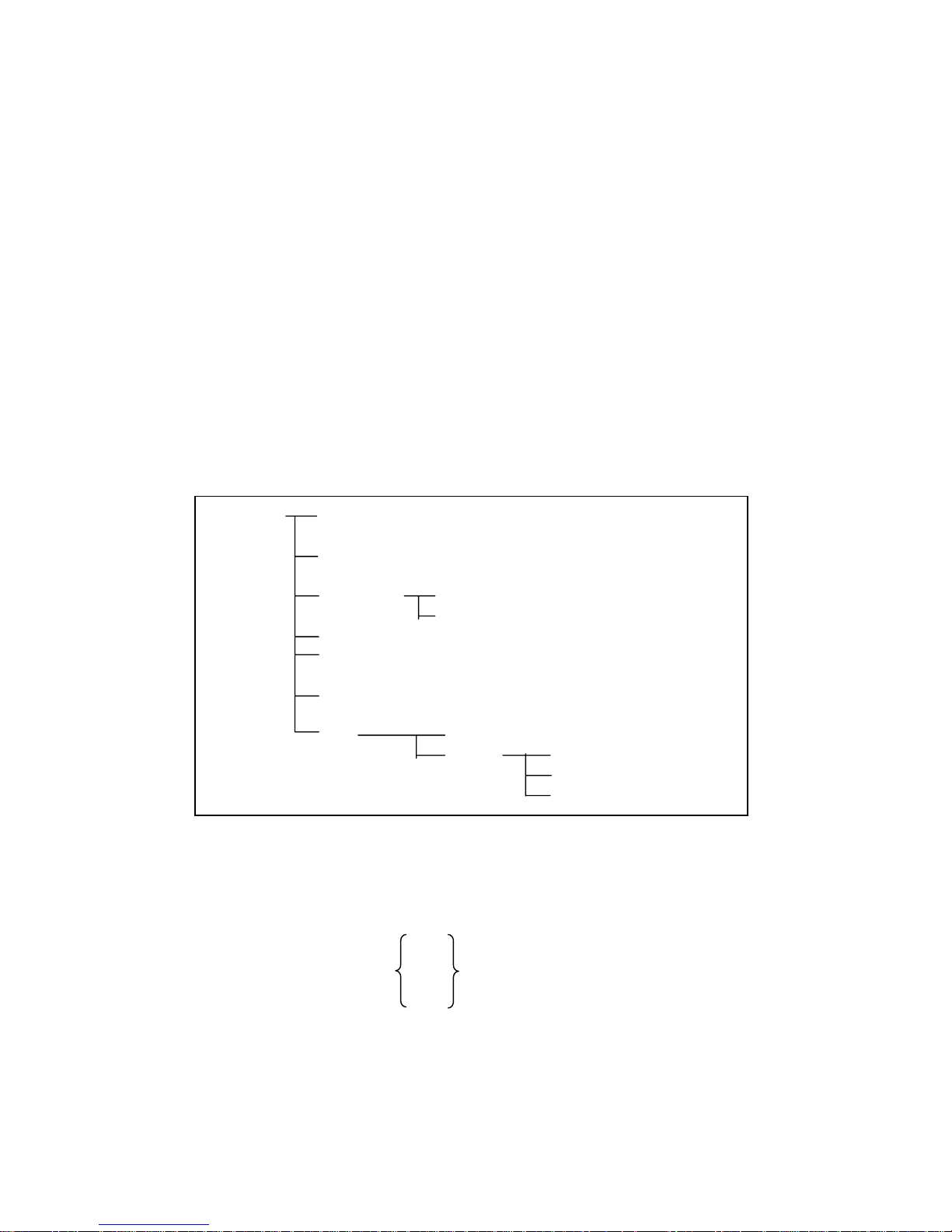
71
Where,
1 (decimal 49) When the function is ON
0 (decimal 48) When the function is OFF
Example
WrtCmd(“CORR:SHOR:STAT ON”)
Query Syntax
CORRection:SHORt:STATe?
Query Response
Returned format is :
<NR1><NL^END>
6.5.10 COMParator Subsystem
The COMParator subsystem command group sets the comparator function, including
its ON/OFF setting, limit mode, and limit values. Figure 6-8 shows the command tree
of the COMParator subsystem command group.
COMParator [:STATe] ON (1)
OFF (0)
:MODE Absolute TOLerance
Percent TOLerance
:TOLerance :NOMinal <value>
:BIN<n> <low limit>,<high limit>
:Secondary LIMit <low limit>,<high limit>
:Auxiliary BIN ON (1)
OFF (0)
:SWAP ON (1)
OFF (0)
:BIN :CLEar
:COUNt [:STATe]
:DATA?
:CLEar
Figure 6-8. COMParator Subsystem Command Tree
[:STATe]
The [:STATe] command sets the comparator function to ON or OFF. The [:STATe]?
query responds the current ON/OFF condition of comparator function.
Command Syntax
ON
COMParator[:STATe] OFF
1
0
Where,
1 (decimal 49) When the function is ON
0 (decimal 48) When the function is OFF
Example
WrtCmd(“COMP ON”)
Page 72

72
Query Syntax
COMParator[:STATe]?
Query Response
Returned format is :
<NR1><NL^END>
:MODE
The :MODE command sets the limit mode of the comparator function. The :MODE?
query returns the current settings of the limit mode.
Command Syntax
ATOLerance
COMParator:MODE
PTOLerance
Where,
ATOLerance Set the absolute tolerance mode (parameter value)
PTOLerance Set the percent tolerance mode (the ratio in percent)
Example
WrtCmd(“COMP:MODE ATOL”)
Query Syntax
COMParator:MODE?
Query Response
Returned format is:
ATO L
<NL^END>
PTOL
:TOLerance:NOMinal
The :TOLerance:NOMinal command sets the nominal value for the tolerance mode of
the comparator function. This can be set only when the limit mode is set to the
tolerance mode. The :TOLerance:NOMinal? query returns the current settings of the
nominal value for the tolerance mode.
Command Syntax
COMParator:TOLerance:NOMinal <value>
Where,
<value> is the NR1, NR2, or NR3 format with suffix ma, k, m, u, m, p.
Example
WrtCmd(“COMP:TOL:NOM 100E-12”)
Query Syntax
COMParator:TOLerance:NOMinal?
Query Response
Returned Format is:
<NR3><NL^END>
Page 73

73
:TOLerance:BIN<n>
The :TOLerance:BIN<n> command sets the low/high limit values of each BIN for the
comparator function tolerance mode. These limits can be set only when the limit
mode is set to the tolerance mode. The :TOLerance:BIN<n>? query returns the
current settings of the low/high limit values of each of the BINs.
Command Syntax
COMParator:TOLerance:BIN<n> <low limit>,<high limit>
Where,
<n> 1 to 4 (NR1) : BIN number
<low limit> NR1, NR2, or NR3 format with suffix ma, k, m, u, n, p.
<high limit> NR1, NR2, or NR3 format with suffix ma, k, m, u, n, p.
Note The low limit value should be lower than the high limit value. If the low limit
value is set higher than the high limit, a warning message is displayed when
this command is received (an error does not occur).
Example
WrtCmd(“COMP:TOL:BIN1 -5,5”)
WrtCmd(“COMP:TOL:BIN2 -10,10”)
Query Syntax
COMParator:TOLerance:BIN<n>?
Query Resopnse
Returned Format is:
<low limit>,<high limit><NL^END>
Low limit and high limit are NR3 format. If the current limits are not set, “9.9E37,
9.9E37” will be returned.
:Secondary LIMit
The :Secondary LIMit command sets the low/high limit values for the comparator
function secondary parameter. The :Secondary LIMit? query returns the current
settings of the secondary parameter low/high limit values.
Command Syntax
COMParator:SLIMit <low limit>,<high limit>
Where,
<low limit> is the NR1, NR2, or NR3 format with suffix ma, k, m, u, n, p.
<high limit> is the NR1, NR2, or NR3 format with suffix ma, k, m, u, n, p.
Note: The low limit value should be lower than the high limit value. If the low limit
value is set higher than the high limit, a warning message is displayed when
this command is received (an error does not occur).
Example
WrtCmd(“COMP:SLIM 0.001,0.002”)
Query Syntax
COMParator:SLIMit?
Query Response
Returned Format is:
Page 74

74
<NR3>,<NR3><NL^END>
If the current secondary limits are not set, “9.9E37” will be returned.
:Auxiliary BIN
The :Auxiliary BIN command sets the auxiliary BIN of the comparator to ON or OFF.
The :Auxiliary BIN? query responds the current ON/OFF condition of the auxiliary
BIN.
Command Syntax
ON
COMParator:Auxiliary BIN OFF
1
0
Where,
0 (decimal 48) When the function is OFF
1 (decimal 49) When he function is ON
Example
WrtCmd(“COMP:ABIN ON”)
Query Syntax
COMParator:Auxiliary BIN?
Query Response
Returned Format is:
<NR1><NL^END>
:SWAP
The :SWAP command sets the swap parameter function to ON (3 BIN settings for
secondary parameter) or OFF (3 BIN settings for primary parameter). The :SWAP?
query responds the current ON/OFF condition of the swap parameter function.
Command Syntax
ON
COMParator:SWAP OFF
1
0
Where,
0 (decimal 48) When the function is OFF
1 (decimal 49) When the function is ON
Example
WrtCmd(“COMP:SWAP ON”)
Query Syntax
COMParator:SWAP?
Query Response
Returned Format is:
<NR1><NL^END>
:BIN:CLEar
Page 75

75
The :BIN:CLEar command clears all of the limit value settings.
Command Syntax
COMParator:BIN:CLEar
Example
WrtCmd(“COMP:BIN:CLE”)
:BIN:COUNt[:STATe]
The :BIN:COUNt[:STATe] command sets the BIN count function to ON or OFF.
The :BIN:COUNt[:STATe]? query responds with the current ON/OFF condition of the
BIN count function.
Command Syntax
ON
COMParator:BIN:COUNt[:STATe] OFF
1
0
Where,
0 (decimal 48) When the function is OFF
1 (decimal 49) When the function is ON
Example
WrtCmd(“COMP:BIN:COUN ON”)
Query Syntax
COMParator:BIN:COUNt[:STATe]?
Query Response
Returned Format is:
<NR1><NL^END>
:BIN:COUNt:DATA?
The :BIN:COUNt:DATA? query returns the comparator BIN count results.
Query Syntax
COMParator:BIN:COUNt:DATA?
Query Response
Returned Format is:
<BIN1 count>,<BIN2 count>, <BIN3 count>,<OUT OF
BIN count>, <AUX BIN count><NL^END>
Where,
<BIN1-3 count> NR1 format : count result of BIN1-9
<OUT OF BINS count> NR1 format : count result of OUT OF BINS
<AUX BIN count> NR1 format : count result of AUX BIN
:BIN:COUNt:CLEar
The :BIN:COUNt:CLEar command clears all BIN counts.
Command Syntax
COMParator:BIN:COUNt:CLEar
Page 76
76
Example
WrtCmd(“COMP:BIN:COUN:CLE”)
6.5.11 Mass MEMory Subsystem
The Mass MEMory subsystem command group loads or stores setting data from/to
the internal EEPROM.Figure 6-9 shows the command tree of the Mass MEMory
subsystem command group.
Mass MEMory :LOAD :STATe <record number>
:SAVE或STORe :STATe <record number> [,<“filename”>]
Figure 6-9. Mass MEMory Subsystem Command Tree
:LOAD:STATe
The :LOAD:STATe command loads the setting data from the internal EEPROM.
Command Syntax
MMEMory:LOAD:STATe <value>
Where,
<value> 0 to 11 (NR1) : file number for internal EEPROM
Example
WrtCmd(“MMEM:LOAD:STAT 1)
If the file number is not available, the message “Record Not Exist” will be displayed in
the message window.
The file contains the page information. When a file is loaded, the instrument will
display the saved page.
:STORe:STATe/ :SAVE:STATe
The :STORe:STATe or :SAVE:STATe command stores the setting data to the internal
EEPROM.
Command Syntax
MMEMory:STORe:STATe <value>[,<”filename”>]
Where,
<value> 0 to 11 (NR1) : record number for EEPROM
<”filename”> The file name consists of not more than 18 characters.
<Unnamed> will be the default name, if you don’t input a file name.
Example
WrtCmd(“MMEM:STOR:STAT 1,”#TH2816B*””)
Page 77

77
6.5.12 Common Commands
A common command consists of an asterisk (*) and a header. TH2816B acceptable
GPIB common commands are described as follows.
*RST
The *RST command (reset command) sets the TH2816B to its initial settings.
Command Syntax
*RST
Example
WrtCmd(“*RST”)
*TRG
The *TRG command (trigger command) triggers a measurement. This command also
moves the primary and secondary parameter measurement data into the TH2816B's
output buffer.
Command Syntax
*TRG
This command will be ignored on no measurement pages, and “9.9E37,9.9E37” will
be returned
.
Example
WrtCmd(“*TRG”)
*IDN?
The *IDN? query returns the TH2816B ID.
Query Syntax
*IDN?
Query Response
Returned format is:
<product>,<version>,<NL^END>
Where,
<product> TH2816B Precision LCR Meter
<version> software revision number
Page 78

78
6.5.13 Error and Warning Messages
The bus commands maybe contain error commands, command syntax errors or error
parameters. TH2816B executes a command after the command is checked. If one of
these errors occurs, TH2816B halts the command analysis, and the rest commands
are ignored.
The error messages listed as follows are displayed in the message window.
Error Message Description
Unknow Message! Unrecognized command is received.
Syntax Error!
Unrecognized command or data type is received.
The message unit separator (for example , “;”,”,”) is
improper.
Data Error!
Improper data type used.
Data value was too large.
Data value is not allowed.
Error Parameter. Unrecognized parameter used.
Error Suffix.
Units are unrecognized, or the units are not appropriate.
A suffix is not allowed for this operation.
Data Too Long! Program Data is too long.
Cannot Executed!
Improper command.
For example, frequency set command is sent when frequency
list sweep measurement is performed.
Record Not Exist! Load a file that is not exist.
The note messages listed as follows are displayed in the message window when
some commands are executing.
Note message Description
Open Progress.. Open correction is in progress.
Short Progress.. Short correction is in progress.
Save Progress.. Save control settings is in progress
Query Updated! A new query received when the output buffer is not empty.
Data Print Fail! Data output operation is over time in talk only mode.
Data Corrupt “Data Corrupt” is sent to the bus as a query response, and the
message is not displayed on the LCD.
Page 79

79
Chapter 7 Handler Interface
7.1 Basic Information
The handler interface outputs signals to indicate measurement completed, bin sorting
judgments of the comparator function, and Go/No-Go judgments of the list sweep
comparator function. The handler interface also has an input for an external trigger
signal. Using these signals, TH2816B can easily be combined with a component
handler and a system controller to fully automate component testing, sorting, and
quality control data processing to increase production efficiency. Table 7-1 lists the
handler interface specifications.
Table 7-1 Specifications of Handler Interface.
Decision output for
comparator function
Bin number, out of bins, and rejection status
Decision output for
list sweep
comparator function
IN/OUT at each sweep point and pass/fail for
the result of sequential comparisons
IDX Analog measurement complete
Output signal
(Negative true,
open collector,
opto-isolated)
EOM
Full measurement complete.
Display time is not included on the BinNo Disp
page.
Display time is included on the List Sweep
page.
Input Signal
(Opto-isolated)
TRIG External Trigger, Pulse width≥1μs
7.2 Handler Interface Operation
This paragraph provides information, including a description of the interface signal
lines and their electrical characteristics, necessary to use the Handler Interface.
7.2.1 Signal line definition
The handler interface uses three types of signals, comparison output, control input
and control output. The signal lines for the Comparator Function and the List Sweep
Comparator Function are defined differently for comparison output and control output
signals. The following defines the signals when the handler interface Comparator
Function and the List Sweep Comparator Function are used.
7.2.1.1 Signal Line Used for Comparator Function
The signal definitions used for the Comparator Function are as follows.
Comparison Output Signals:
/BIN1 - /BIN3
/AUX
/OUT
/PHI primary parameter high reject signal
/PLO primary parameter low reject signal
/SREJ secondary parameter reject signal
Control Output Signals:
/IDX analog measurement completed signal
/EOM end of measurement and comparison data valid signal
Page 80

80
Control Input Signal:
/TRIG external trigger signal
The contact assignments and a brief description of each signal used for the
comparator function are given in Table 7-2 and Figure 7-2. The timing diagram is
shown in Figure 7-3.
The /(back slash) in the signal name means that the signal is asserted when low.
Page 81
81
Table 7-2. Pin Assignments For Comparator Function
Pin
No.
Signal
Name
Description
1
2
3
4
5
6
7
8
9
/BIN1
/BIN2
/BIN3
/BIN4
/BIN5
/BIN6
/BIN7
/BIN8
/BIN9
Bin sorting judgments.
All bin sorting signal outputs are opto-isolated open collector.
10
11
/OUT
/AUX
Bin sorting judgments.
All bin sorting signal outputs are opto-isolated open collector.
12
13
/TRIG
/TRIG
External Trigger:
TH2816B is triggered on the rising edge of a pulse applied to this pin
when the trigger mode is set to EXT mode.
14
15
EXV2
EXV2
External DC voltage 2:
DC voltage supply pins for DC isolated control signals (/TRIG, /IDX,
/EOM). Setting of internal jumpers must be changed when using an
internal voltage supply.
16
17
18
VCC
Internal voltage supply (maximum 100 mA)
Setting of internal jumpers must be changed when using an internal
voltage supply.
19 /PHI
Primary Parameter High Reject:
The measurement value is greater than the high limit value of
BIN1–BIN3. (See Figure 7-1)
20 /PLO
Primary Parameter Low Reject:
The measurement value is less than the low limit value of BIN1-BIN3.
(See Figure 7-1)
21 /SREJ
Secondary Parameter Reject:
The measurement value is not within the range of the secondary
parameter limit. (See Figure 7-1)
22
23
24
25
26
NC
NC
NC
NC
NC
No Connection
No Connection
No Connection
No Connection
No Connection
27
28
EXTV1
EXTV1
External DC voltage 1:
DC voltage supply pins for DC isolated open collector outputs,
/BIN1-/BIN3, /AUX, /OUT, /PHI, /PLO, /SREJ. The setting of internal
jumpers must be changed when using the internal voltage supply.
29 NC No Connection
30 /IDX
/IDX signal is asserted when an analog measurement is completed
and TH2816B is ready for the next DUT to be connected to the
UNKNOWN terminals. The measurement data, however, is not valid
until /EOM is asserted. (See Figure 7-3)
31 /EOM
End of Measurement:
This signal is asserted when the measurement data and comparison
results are valid. (See Figure 7-3)
32
33
COM2
COM2
Common for EXTV2
34
35
36
COM1
COM1
COM1
Common for EXTV1
Page 82
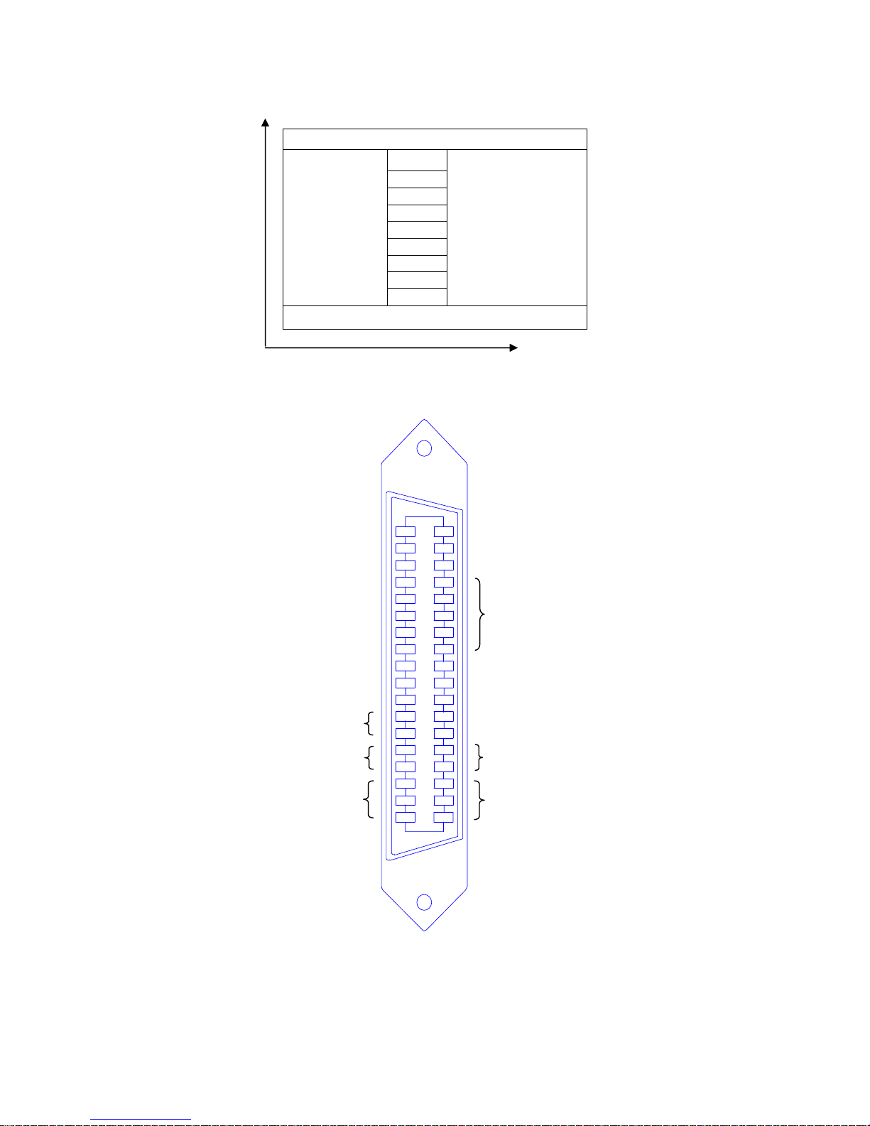
82
1
2
3
4
5
6
7
8
9
10
11
12
13
14
15
16
17
18
19
20
21
22
23
24
25
26
27
28
29
30
31
32
33
34
35
36
/BIN1
/BIN2
/BIN3
/BIN4
/BIN5
/BIN 6
/BIN7
/BIN8
/BIN9
/OUT
/AUX
/TRIG
/EXV2
/V CC
/PHI
/PL O
/SREJ
N.C
EXV1
N.C
/IDX
/EOM
COM
2
COM
1
Primary
Parameter
Secondary Parameter
Figure 7-1. /PHI, /PLO, /SREJ Signal’s Area Example
Figure 7-2 Pin Assignment For Handler Interface Connector
PHI(OUT)
BIN 1
BIN 2
BIN 3
BIN 4
BIN 5
BIN 6
BIN 7
BIN 8
SREJ(AUX)
BIN 9
SREJ(AUX)
PLO(OUT)
Page 83
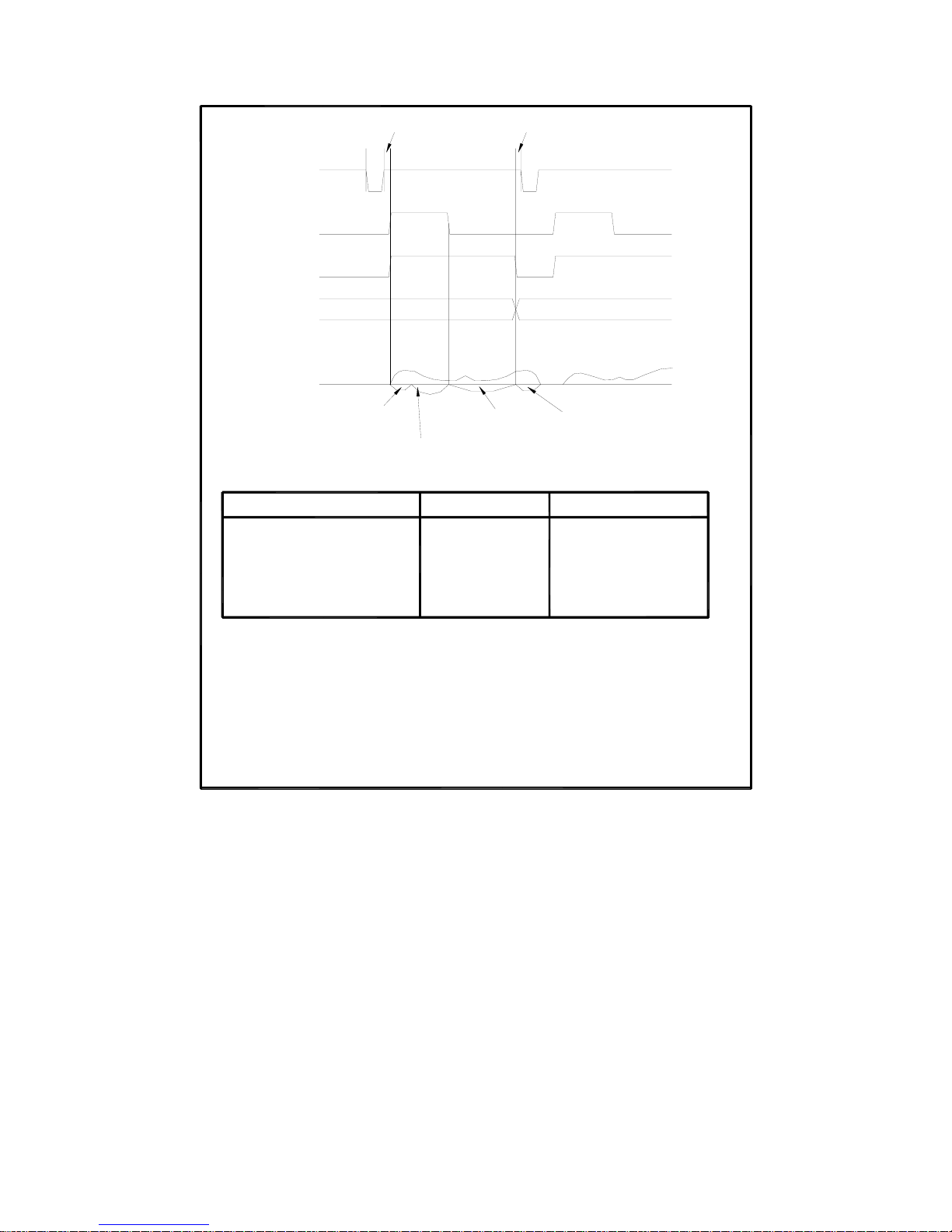
83
BinNo. Disp page approx. 8ms
Bin Count page approx. 5ms
Large Character Display : approx. 50ms
Normal Character Display : approx. 3ms
Vm/Im Monitor ON : Plus 2ms
MeasDisplay page:
Measurement
Time
Typical display time for each display format is as follows.
Typical calculation and comparison time is 2ms;
a measurement
Previous Data Valid
T3 Trigger Wait Time
After /EOM Output
Delay Time
T
2 Measurement Start
T
1 Trigger Pulse Width
Time
Timing
Measurement
2
1
Delay
Time
/EXT TRIG
Data
/EOM
/IDX
-
T
2
T1
---
Display Time +200
---
Maximum Value
a measurement
Minimum Value
Comparison
Time
200μs
0μs
1μs
Display
Time
T3
Data Valid
μs
Figure 7-3 Timing Diagram
7.2.1.2 Signal Line Used for List Sweep Comparator Function
Signal definition used for the list sweep comparator function is different from that used
for the comparator function. Signal definition used for the list sweep comparator
function is as follows.
Comparison Output Signals:
/BIN1-BIN3 and /OUT indicate IN/OUT judgments for each sweep point (refer to
Figure 7-4). /AUX indicates pass/fail judgment (one or more failed judgments of
steps 1 to 4 occurred during a single sweep).
These signals are output when the sweep measurement is completed.
Control Output Signals:
/IDX (analog measurement completed signal) and /EOM (end of measurement
signal). The timing when /IDX and /EOM are asserted is as follows: (different
from that used for the comparator function).
In the SEQ sweep mode:
/IDX is asserted when the last step of an analog measurement of a sweep
Page 84

84
measurement is completed. /EOM is asserted when all of the comparison results
are valid after a sweep measurement.
In the STEP sweep mode:
/IDX is asserted after each step of analog measurement in a seep measurement
is completed. /EOM is asserted after each step measurement, inclding
comparison time, is completed.
The contact assignments and a brief description of signals used for the list sweep
function are given in Table 7-3 and Figure 7-2 (pin assignments for the list sweep
comparator function are the same as for the comparator function). The timing
diagram is shown in Figure 7-5.
The /(back slash) in the signal name means that the signal is asserted when LOW.
Table 7-3 Contact Assignments for List Sweep Comparator Function
Pin No. Signal
Name
Description
1
2
3
4
5
6
7
8
9
10
/BIN1
/BIN2
/BIN3
/BIN4
/BIN5
/BIN6
/BIN7
/BIN8
/BIN9
/OUT
Failed (out of limit ) at sweep Point 1
Failed (out of limit ) at sweep Point 2
Failed (out of limit ) at sweep Point 3
Not Used
Not Used
Not Used
Not Used
Not Used
Not Used
Failed (out of limit ) at sweep Point 4
11 /A U X
/AUX is asserted when one or more file judgments of Steps 1
to 10 occur in a single sweep.
12-18 Same as the assignments for the comparator function (Refer
to Table 7-2).
19-21 N.U Not Used (Off state, HIGH level)
22-29 Same as the assignments for the comparator function (Refer
to Table 7-2).
30 /IDX In the SEQ sweep mode:
/IDX is asserted when an analog measurement of the last
sweep step is completed, and TH2816B is ready for the next
DUT to be connected to the UNKNOWN terminals. The
measurement data, however, is not valid until/EOM is
asserted. (See Figure 7-5)
In the STEP sweep mode:
/IDX is asserted when each analog measurement is complete
and TH2816B is ready for the next sweep step. The
measurement data, however, is not valid until /EOM is
asserted (See Figure 7-5).
31 /EOM End of Measurement
In the SET sweep mode :
/EOM is asserted when the measurement data and
comparison results are valid after the last step measurement
is completed. (See Figure 7-5.)
In the STEP sweep mode:
/EOM is asserted when each step measurement, including the
comparison times, is completed and the measurement data is
valid. The comparison results are valid after the /EOM signal
of the last sweep point is asserted. (See figure 7-5)
32-36 Same as the assignments for the comparator function (Refer
to Table 7-2).
Page 85
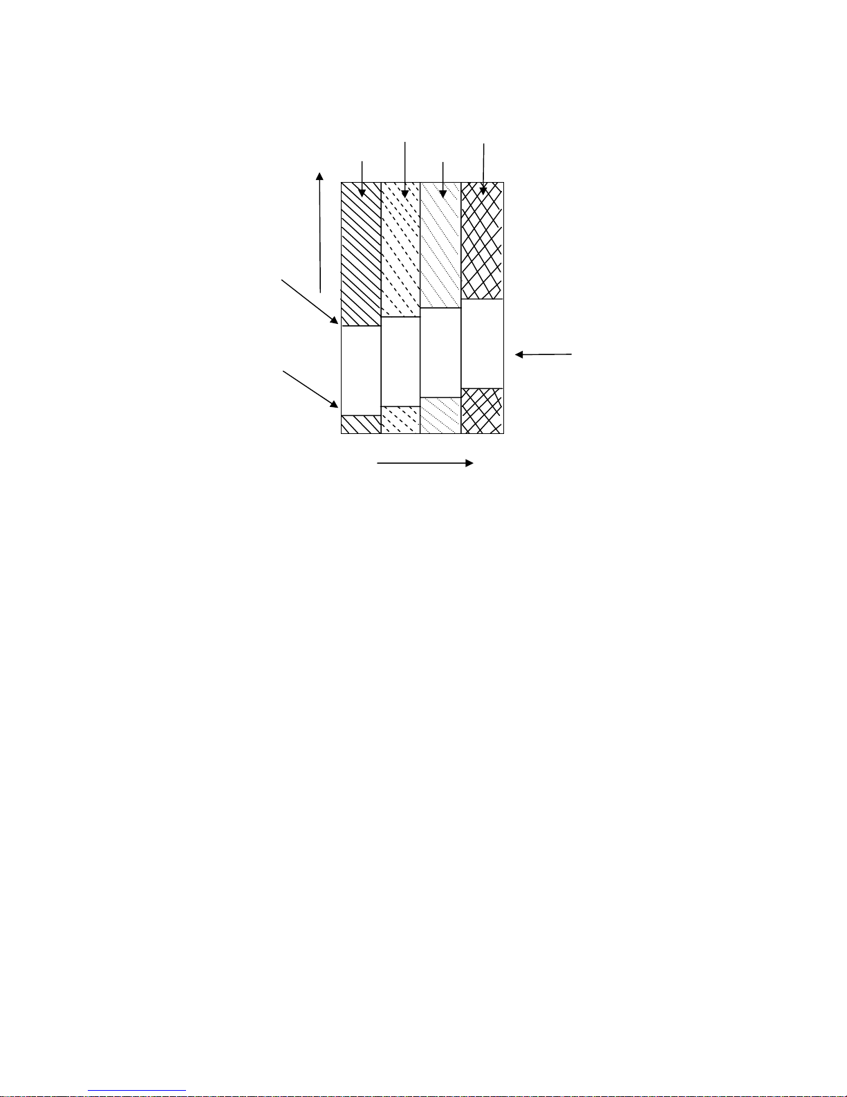
85
/BIN2 /OUT
/BIN1 /BIN3
Measurement
Data
High Limit
Pass Area
Low Limit
1 2 3 4
Sweep Point
Figure 7-4 Signal Area Example
(For The List Sweep Comparator Function)
Page 86
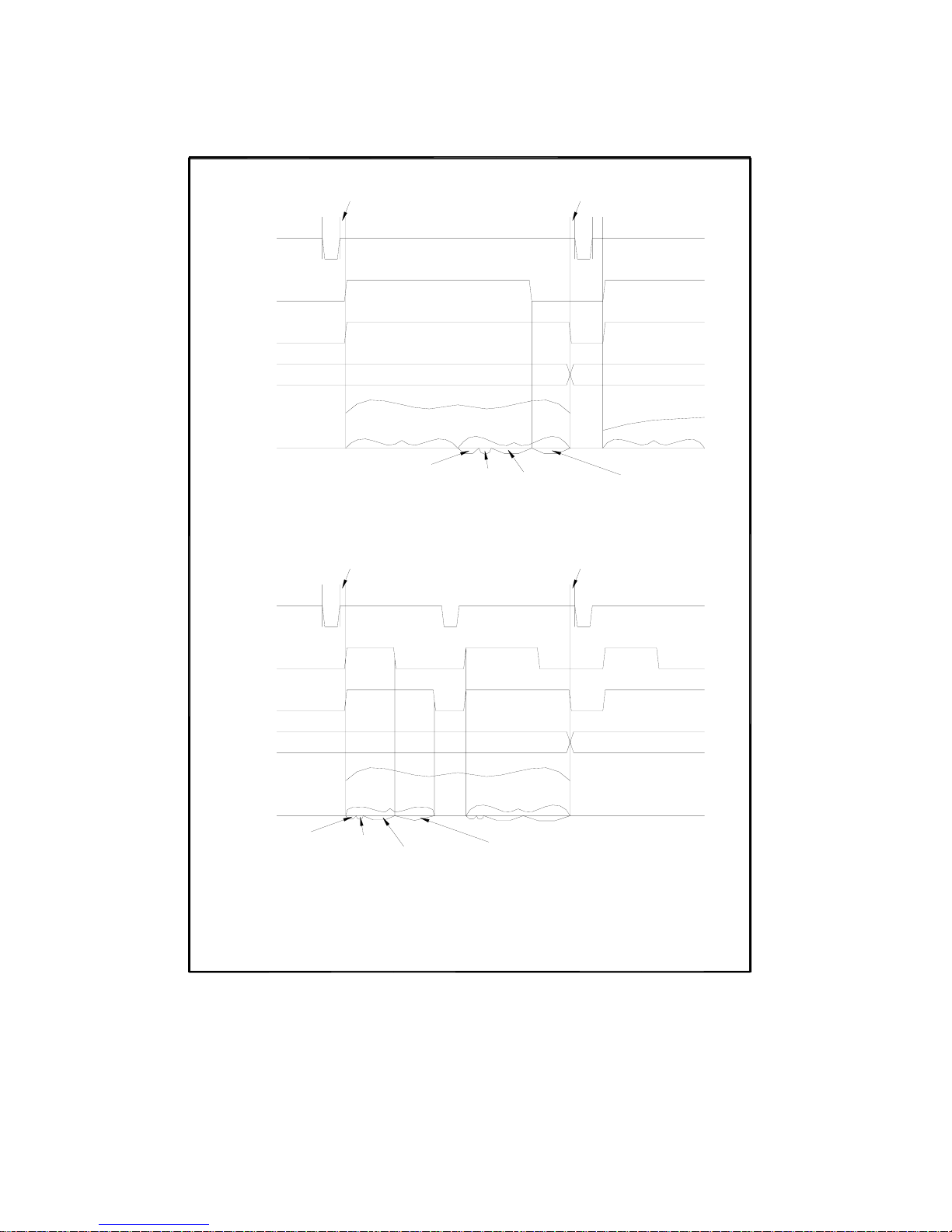
86
Calculation, Comparison and Display Time is approx. 5ms.
Refer to Figure 7-3 for information of T1, T2, T3.
Setting Time includes Correction Data Switching Time.
STEP Sweep Mode:
Measurement
Time
Previous Sweep's Data Valid
a measurement
a measurement
Previous Sweep's Data Valid
Timing
2.
1.
Delay
Time
Setting
Time
/TRIG
/EOM
/IDX
Data
Measurement
Measurement
Timing
T1
T2
SEQ Sweep Mode:
/TRIG
/IDX
Data
/EOM
T
2
T1
Calculation,
Comparison and
Display Time
NOTE
Calculation,
Comparison and
Display Time
Data Valid
Data Valid
a measurement
a measurement
a sweep
Setting
Time
Delay
Time
Measurement
Time
T
3
a sweep
T
3
Figure 7-5 Timing Diagram for List Sweep Comparator Function
Page 87

87
7.3 Electrical Characteristics
As mentioned in the previous paragraph, the meaning of some of the signals is
different for the comparator function and the list sweep comparator function. However,
the electrical characteristics of these signals are identical for the two operations. The
following descriptions apply to both the comparator function and the list sweep
comparator function.
7.3.1 DC Isolated Outputs
Each DC output (pins 1 through 11, pins 19 through 21, pins 30 through 31) is
isolated using an open collector output opto-coupler. The output voltage of each line
is set by a pull-up resistor on the handler interface board. The pull-up resistors can be
connected to the internally supplied voltage (+5V), or to an externally applied voltage
( EXTV: +5V to +24V) by setting jumpers.
The electrical characteristics of the DC isolated outputs are divided into two types.
(See Table 7-4)
Since the power source for the Comparison Output and Control Output signals are
different, two circuit commons (COM1, COM2) are made available.
Table 7-4 DC Isolated Output Electrical Characteristics
A simplified diagram of the output signals in shown in Figure 7-6 (Comparison Signals)
and Figure 7-7 (Control Signals).
Voltage Output
Rating
Output Signals
Low High
Maximum
Current
Circuit Common
Comparison Signals
/BIN1 - /BIN3
/OUT
/AUX
/PHI
/PLO
/SREJ
≤0.5V +5V to +24V 6mA
Internal pull-up voltage:
TH2816B circuit common
(GND)
External voltage (EXTV1):
COM1
Control Signals
/IDX
/EOM
≤0.5V +5V to +24V 6mA
Internal pull-up voltage:
TH2816B circuit common
(GND)
External voltage (EXTV2):
COM2
Page 88
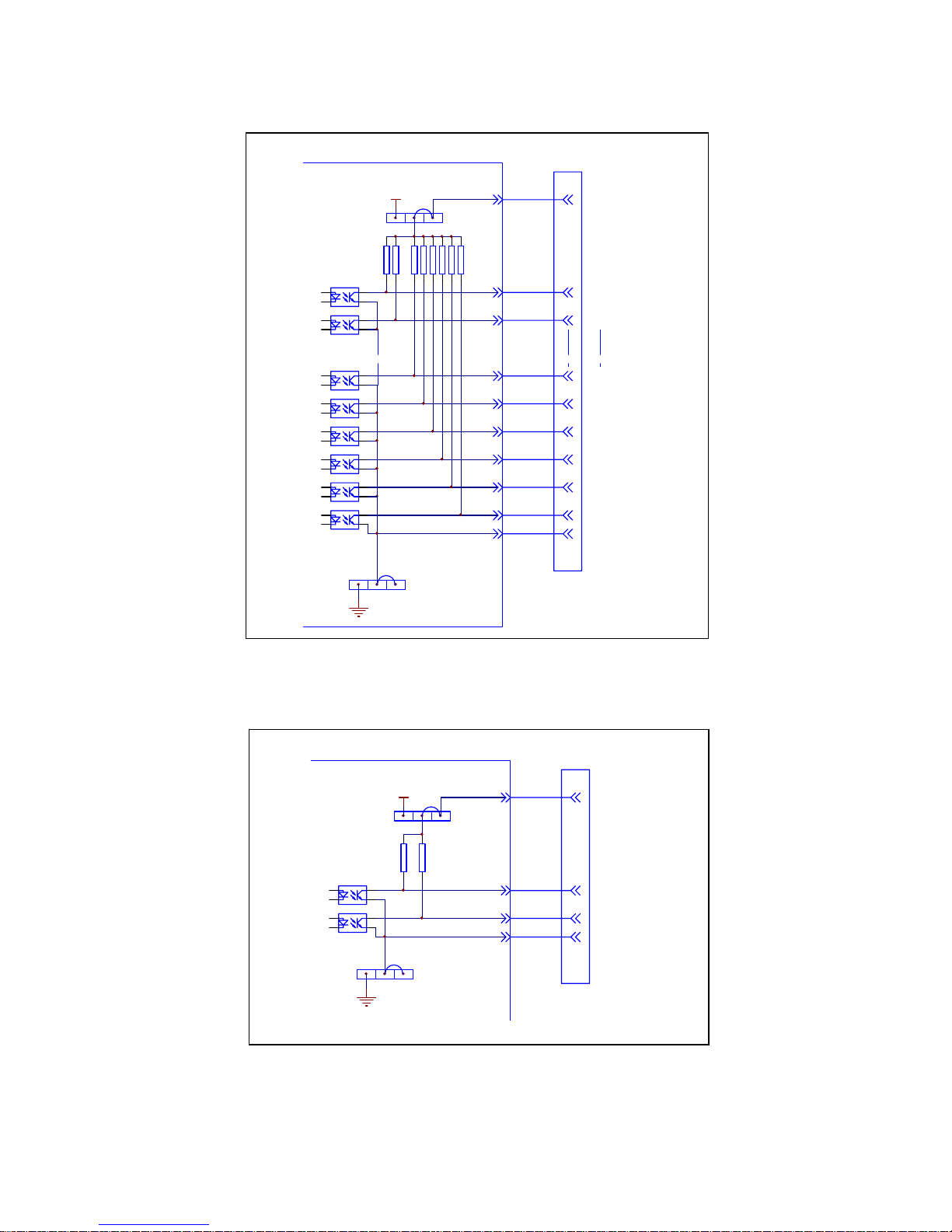
88
VCC
J904
J903
HANDLER
接口板
EXV2
/IDX
/EOM
COM2
接口连接器
HANDLER
14,15
30
31
32,33
上拉电阻
4.7k
内部
+5V
电源
仪器参考地
*
*
VCC
J901
J902
HANDLER
接口板
EXV1
/BIN1
/BIN2
/BIN9
/OUT
/AUX
/PHI
/PLO
/SREJ
COM1
接口连接器
HANDLER
27,28
1
2
9
10
11
19
20
21
34, 35, 36
上拉电阻
4.7k
内部
+5V
电源
仪器参考地
*
*
*为出厂时默认的跳线位置
Figure 7-6 Simplified Diagram of The Comparison Output Signals
*为出厂时默认的跳线位置
Figure 7-7 Simplified Diagram of The Control Output Signals
Page 89
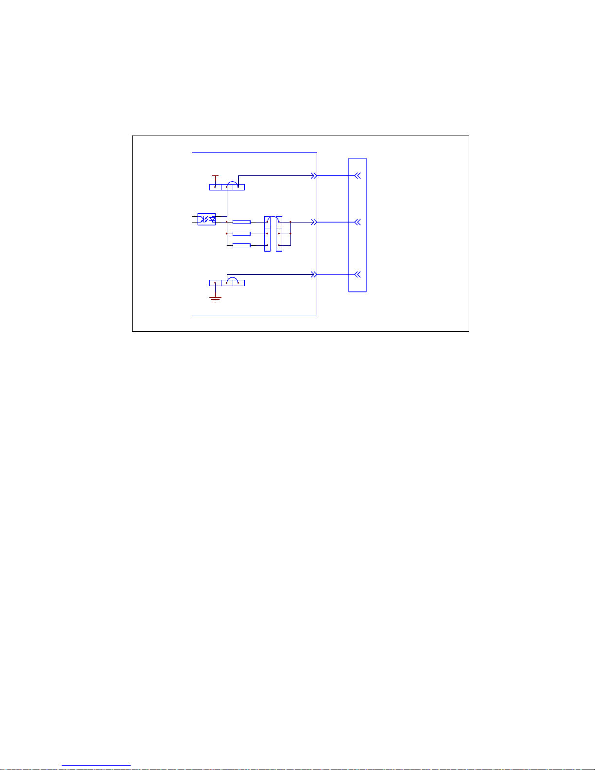
89
680
1.2k
VCC
J905
J903
HANDLER
接口板
EXV2
/TRIG
COM2
接口连接器
HANDLER
14,15
12,13
32,33
触发限流电阻
内部
+5V
电源
*
*
2.2k
J904
仪器参考地
*
7.3.2 DC Isolated Input
The /TRIG signal (pin 12 and 13) is connected to the cathode of the LED in an
opto-coupler. TH2816B is triggered on the rising edge of the /TRIG pulse. The anode
of the LED can be powered from the internal 5 V, or by an external voltage source
EXTV2.
*为出厂时默认的跳线位置
Figure 7-8 Handler Interface Input Signal Diagram
T
o limit the trigger current, jumper J905 must be selected considering the optocoupler
anode voltage being used.
7.4 Setting Up the Handler Interface Board
Jumpers on the Handler Interface board must be set to select the signal outputs
(Open collector, internal voltage outputs, or External voltage outputs). A description of
each jumper is given in Table 7-5, and their locations are shown in Figure 7-9.
When shipped from the factory, each jumper is set to the (N) position (marked “N” on
the handler interface board).
Jumper J901 and J902 are used to select the internal voltage or external voltage for
the output signals.
Jumper J903 and J904 are used to select the internal voltage or external voltage for
the control signals.
Jumper J905 is used to select the current limiting resistor under different voltage
range.
Page 90
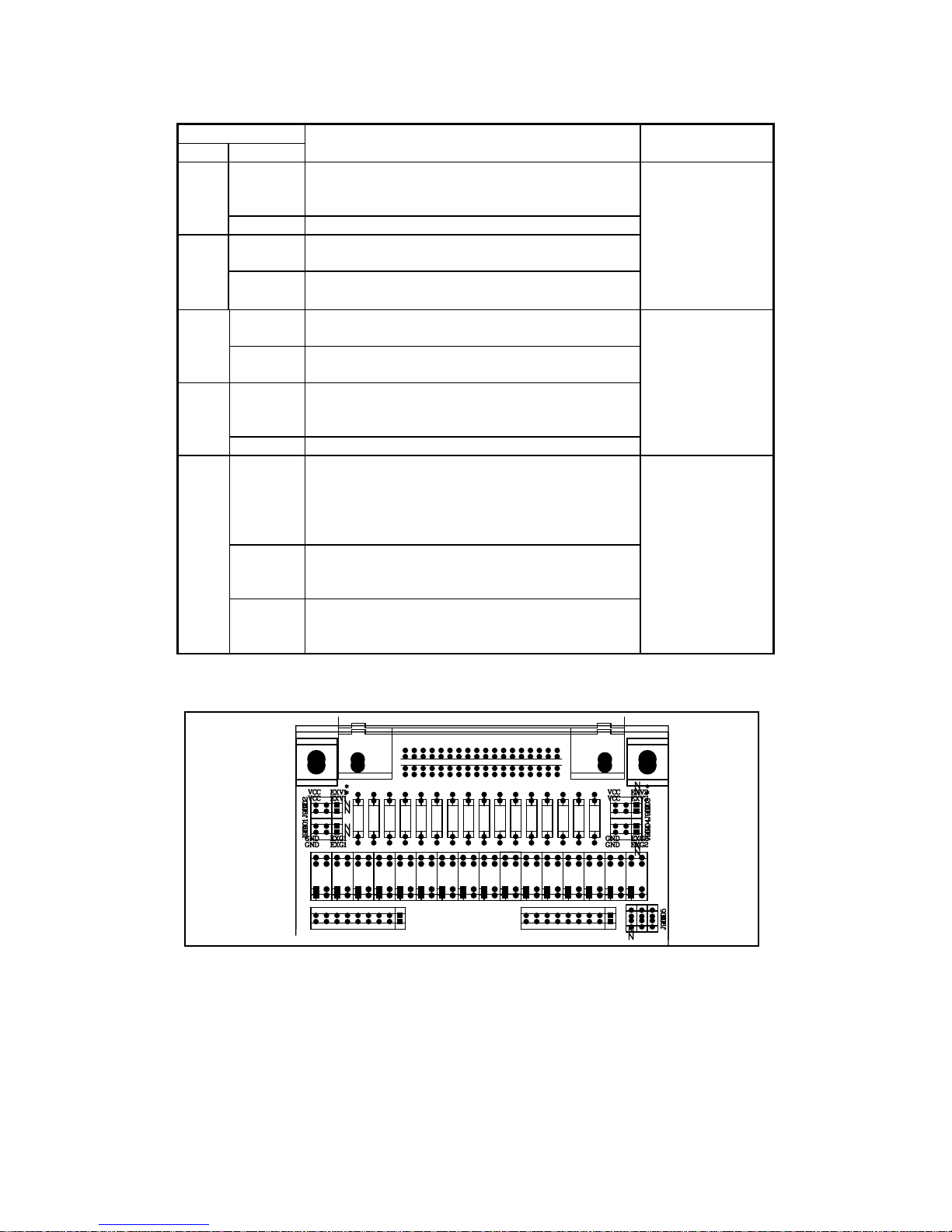
90
Jumper
No. Position
Description Signals
Left
DC isolated outputs are not isolated.
COM1 is connected to TH2816B circuit
common.
J901
Right(N) DC isolated outputs are isolated.
Left
The open collector outputs are pulled up to the
internal VCC (+5 V).
J902
Right(N)
The open collector outputs are pulled up to the
external EXV1(+5V to +24V)。
/BIN1-/BIN3
/AUX
/OUT
/PHI
/PLO
/SREJ
Left
The open collector outputs are pulled up to the
internal VCC (+5V).
J903
Right(N)
The open collector outputs are pulled up to the
external EXV2 (+5V to +24V).
Left
DC isolated outputs are not isolated.
COM2 is connected to TH2816B circuit
common.
J904
Right(N) DC isolated outputs are isolated.
/IDX
/EOM
/TRIG
Left (N)
Trigger current limiting resistor is 680Ω.
This position should be set when EXV2 is
between 5V to 8V or when internal VCC is
used for control signals (J903 and J904 are set
to the left position).
Center
Trigger current limiting resistor is 1.2kΩ.
This position should be set when EXV2 is
between 8V to 15V.
J905
Right
Trigger current limiting resistor is 2.2kΩ.
This position should be set when EXV2 is
between 15V to 24V.
/TRIG
Figure 7-9. Handler Interface Input Signal Diagram
Page 91
91
7.5 Operation
To use the handler interface, after setting up the handler interface board, setup the
limit table for using the comparator function or the list sweep setup table for using the
list sweep comparator function. Then set the handler interface to be enabled to
output/input the signals. The following procedures are for using the handler interface
with the comparator function or the list sweep comparator function.
7.5.1 Setting Procedure For Comparator Function
The following operation procedures are for using the handler interface with the
comparator function.
1) Set the measurement function, test frequency, oscillator signal level, and
measurement speed on the Meas Setup page.
2) Press the SETUP menu key, and the LIMIT softkey. The Limit Table will be
displayed.
3) Move the cursor to the FUNC field, and set if the parameter swap function is
used.
4) Move the cursor to the MODE field, and set the comparator limit mode: %TOL or
±TOL.
5) Move the cursor to the COMP field, and press softkey ON to enable the
comparator function.
6) Move the cursor to the AUX field. Press softkey ON to enable the AUX BIN,
then a device whose primary parameter is within limits, but whose secondary
parameter measurement result is not within limits will be sorted into an AUX BIN.
7) The EXT trigger mode is always be used, when a handler interface is used. Press
SETUP menu key, move the cursor to the TRIG field and set the trigger mode to
EXT. Check if the deviation display mode DEV_A/DEV_B is set to OFF.
8) Press DISPLAY menu key. To perform a measurement, select the LCR, BinNo,
COUNT softkey.
9) Comparator function are always used for sorting large amount of components
with the same nominal value, so range hold function may be used to increase the
measurement efficiency.
10) Move the cursor to the File field, use the SAVE softkey to save the current control
settings and limit table to a file.
7.5.2 Setting Procedure For List Sweep Comparator function
The following operation procedures are for using the handler interface with the list
sweep comparator function.
1) Set the measurement function, test frequency, oscillator signal level, and
measurement speed on the Meas Setup page.
2) The EXT trigger mode is always be used, when a handler interface is used. Press
SETUP menu key, move the cursor to the TRIG field and set the trigger mode to
EXT. Set deviation display mode DEV_A/DEV_B to ON if you want.
3) Press the SETUP menu key, and the LIST softkey. The List Setup page will be
displayed.
4) Setup a list table including sweep parameter points, parameter compared, and
high/low limits for the list sweep measurement.
5) Move the cursor to the MODE field, and set the sweep mode: SEQ or STEP.
6) Auto ranging always be selected, considering the delay time and source output
impedance.
7) Press DISPLAY menu key. To perform list sweep measurement, select the
SWEEP softkey.
8) Move the cursor to the File field, use the SAVE softkey to save the current control
settings and list table to a file.
 Loading...