

Page 1

OPERATION MANUAL
TH2810B LCR METER
TH2618B CAPACITANCE METER
TH2775B INDUCTANCE METER
1
Page 2

NOTICE
Thanks for purchasing and using our product. Please confirm the product set
and accessories with shipment list. If there is any unconformity, please contact
sales office or Tonghui Company as soon as possible to protect your benefits!
DESCRIPTION
Refer to descriptions of front and rear panels in § 1.6 on P 1-6.
WARNING
To avoid electric shock hazard, please make sure that phase line, zero line and
ground line are connected correctly before the instrument is plugged into an
outlet. The instrument chassis and cabinet must be connected to a safety earth
ground to avoid the cover to be electrified.
WARNING
Take care not to contact the parts with 220V when making maintenance to avoid
the hazard of electrical shock. It is absolutely prohibited to perform normal
measurement when the cover is removed (except for maintenance and
adjustment).
WARNING
Do not plug in or out component or connecting line when the instrument is
switched on to avoid unnecessary damage to component or instrument. It is not
permitted to turn on or off instrument continuously to avoid causing program
inordinate, which will lose proofread and saved data.
ATTENTION
The calibration of the instrument should be done by professional personnel.
Should trouble occur in EEPROM 28C64, it must be returned to the company to
avoid losing accuracy calibration data.
DECLARATION
We are likely to improve our equipment without extra explanation, including the
performance, functions, inner structure, appearance, accessories, and packing.
2
Page 3

CONTENTS
Chapter 1 General introduction ............................................................................................5
1.1 Brief introduction......................................................................................................5
1.2 Specifications ............................................................................................................5
1.2.1 Measurement terminals .....................................................................................5
1.2.2 Measurement parameters...................................................................................6
1.2.3 Display range ....................................................................................................6
1.2.4 Measurement accuracy......................................................................................6
1.2.4.1 Maximum and minimum values for different ranges.................................... 7
1.2.4.2 Deviation factor ks ........................................................................................7
1.2.4.3 Level factor kv ..............................................................................................7
1.2.4.4 Frequency factor kf .......................................................................................7
1.2.5 Test signal frequency ........................................................................................7
1.2.6 Test signal level.................................................................................................7
1.2.7 Output impedance of measurement signal ........................................................7
1.2.8 Measurement speed...........................................................................................8
1.2.9 Inputting data range...........................................................................................8
1.3 Operating environment..............................................................................................8
1.3.1 Temperature & Humidity ..................................................................................8
1.3.2 Power ................................................................................................................8
1.3.3 Warm-up ...........................................................................................................8
1.3.4 Notice ................................................................................................................9
1.4 Dimensions and weight.............................................................................................9
1.5 Function index...........................................................................................................9
1.6 Panel........................................................................................................................10
1.6.1 Rear panel description.....................................................................................10
1.6.2 Front Panel Description...................................................................................11
Chapter 2 Operation instruction .........................................................................................14
2.1 Keyboard and functions introduction......................................................................14
2.2 Function conversion in “measurement” state..........................................................16
2.2.1 Measurement parameters.................................................................................16
2.2.2 Measurement frequency ..................................................................................17
2.2.3 Test signal level...............................................................................................17
2.2.4 Display mode ..................................................................................................17
2.2.4.1 Direct.......................................................................................................17
2.2.4.2 △% .........................................................................................................18
2.2.5 Range mode.....................................................................................................18
2.2.5.1 Range definition and its range.................................................................18
2.2.5.2 Range Hold..............................................................................................19
2.2.6 Measurement speed.........................................................................................19
2.2.7 Clear (Correction) ...........................................................................................20
2.3.1 Alarm ..............................................................................................................22
3
Page 4

2.3.2 Trigger (continuous/single) .............................................................................22
2.3.3 Equivalent model ............................................................................................22
2.3.4 Serial interface ................................................................................................23
2.3.5 Sorting mode ...................................................................................................28
2.3.5.1 Sorting procedure....................................................................................29
2.3.5.2 Handler interface.....................................................................................30
2.3.6 Signal source resistance ..................................................................................32
2.3.7 Key lock ..........................................................................................................32
2.3.7.1 Entering key lock ....................................................................................32
2.3.7.2 Exiting key lock ...................................................................................... 32
2.3.7.3 Notices in the state of key lock ...............................................................33
2.3.8 Safeguard ........................................................................................................33
2.4 Parameter setup .......................................................................................................33
Chapter 3 Component measurement ...............................................................................35
3.1.1 Notices ............................................................................................................35
3.1.2 Common component measurement.................................................................35
3.2.1 Measurement of Capacitor ..............................................................................37
3.2.2 Connecting the Component.............................................................................37
Chapter 4 Packing and Warranty .......................................................................................39
4.1 Packing....................................................................................................................39
4.2 Warranty..................................................................................................................39
4
Page 5

Chapter 1 General introduction
This chapter provides brief and concise description of instrument’s
specifications and functions.
1.1 Brief introduction
As a newly developed instrument, TH2810B Series Component Parameter
Testers offer fast, reliable, and versatile testing at a low cost. It can
automatically measure component parameters, including inductance (L),
capacitance (C), resistance (R), impedance (Z), quality factor (Q), and tangent
of dissipation angle (D), etc. This instrument, which merges powerful functions,
excellent performances and simple operation into a whole, can satisfy both the
need for fast test in factories, and the requirement of high precision and stable
measurement in laboratory.
Compared with general component parameter testers, instruments of TH2810B
make improvements in the following aspects:
1. To meet requirements in different situations, the instrument has two sets of
selection programs, and parameter setup is of many digits and high
resolution rate. The instrument can be connected with automatic meter
through interfaces to realize automatic measurement.
2. The instrument provides RS232C interface to effectively communicate with
computer and make it possible to remotely control and collect data.
3. The instrument applies the design method of invariable resistance of signal
source, and it ensures that voltage or current signal in one tested
component does not change with the adjustment of range, to avoid being
hard to select range for tested component which is at the edge of range.
4. The instrument has the functions of locking key and saving state. It can
reduce workers’ incorrect operation, and make personalized default state
possible.
TH2810B Series Component Parameter Testers include TH2810B LCR meter,
TH2618B capacitance meter, and TH2775B inductance meter. And they differ in
measurement parameters (referring to Table 1-1 Measurement Parameters
Table in § 1.2.2). TH2618B and TH2775B only have some functions of TH2810B,
so this manual is applicable to TH2810B and the contents which are only
applicable to TH2618B or TH2775B are marked.
1.2 Specifications
1.2.1 Measurement terminals
There are five terminals, namely HD, HS, LS, LD and GND.
5
Page 6
1.2.2 Measurement parameters
Model Parameter
TH2810B L-Q, C-D, R-D, Z-Q
TH2618B C-D, R-D
TH2775B L-Q, R-Q
Table 1-1.Measurement Parameters
L: inductance C: capacitance R: resistance
Z: impedance Q: quality factor D: tangent of dissipation angle
The instrument provides two kinds of equivalent circuits, series connection and
parallel connection, in which Z, D and Q have the same values while C, L and R
have different values. The conversion relations between the two equivalent
circuits are discussed in Table 2-4 Conversion Table of Circuits in Series and
Parallel Connections on P 2-11.
1.2.3 Display range
L: 0.01µH ~ 99999H
C: 0.01pF ~ 99999µF
R/Z: 0.0001Ω ~ 99999MΩ
D: 0.0001 ~ 9.999
Q: 0.0001 ~ 9999
Δ%: -9999% ~ 9999%
1.2.4 Measurement accuracy
C: 0.1% (1+Cx/Cmax+Cmin/Cx) (1+Dx) (1+ks+kv+kf);
L: 0.1% (1+Lx/Lmax+Lmin/Lx) (1+1/Qx) (1+ks+kv+kf);
Z: 0.1% (1+Zx/Zmax+Zmin/Zx) (1+ks+kv+kf);
R: 0.1% (1+Rx/Rmax+Rmin/Rx) (1+Qx) (1+ks+kv+kf);
2
D: ±0.0010 (1+Zx/Zmax+Zmin/Zx) (1+Dx+Dx
Q: ±0.0015 (1+Zx/Zmax+Zmin/Zx) (Qx+1/Qx) (1+ks+kv+kf).
Notes: 1. D and Q are absolute deviations and others are percent deviations,
Dx=1/Qx;
2. Those with subscript x mean measurement values of the parameters;
those with subscript max mean maximum values and min mean
minimum values;
3. ks is the speed factor; kv is the level factor and kf is the frequency
factor;
4. In order to gain high measurement accuracy, you should make open
and short correction again when the test fixture or conditions are
changed.
) (1+ks+kv+kf);
6
Page 7

1.2.4.1 Maximum and minimum values for different ranges
Parameter
Cmax
Cmin 1500pF 1250pF 150pF 15pF
Lmax 1590H 1325H 159H 15.9H
Lmin 3.2mH 2.6mH 0.32mH 0.032mH
Zmax/
Rmax
Zmin/ Rmin
100Hz 120Hz 1kHz 10kHz
800μF 667μF 80μF 8μF
Table 1-2. Maximum and Minimum Values
Frequency
1.2.4.2 Deviation factor ks
slow speed: ks =0 fast speed: ks =10
1.2.4.3 Level factor kv
When V=1V, kv =0;
When V = 0.3V, kv = 1;
When V = 0.1V, kv = 4.
1MΩ
1.59Ω
1.2.4.4 Frequency factor kf
When f = 100 Hz, 120 Hz or 1 kHz, kf = 0;
When f = 10 kHz, kf = 0.5.
1.2.5 Test signal frequency
Test signal: sine wave
Four frequencies are available: 100Hz, 120 Hz, 1 kHz, 10 kHz
Accuracy: 0.02%.
1.2.6 Test signal level
Three levels are available: 0.1V, 0.3V, 1.0V (effective value)
Accuracy: ±10% (The set value of the measurement level is the value set when
test terminals are opened HD and HS should be connected)
Due to the output impedance of the signal source, the actual level applied upon
the component under test may be different from the set value.
1.2.7 Output impedance of measurement signal
Output impedance: 30 Ω (default value) and 100 Ω, without requirement of
accuracy.
7
Page 8
1.2.8 Measurement speed
Fast: around 15 times/sec.;
Slow: around 4.5 times/sec.;
The actual speed differs with different measurement conditions such as
frequency, component value, display mode, measurement mode, once, range
mode, RS232 interface and so on.
The typical speeds for Fast, Medium and Slow are given under the following
measurement conditions:
· Frequency: 1 kHz or 10 kHz;
· Measurement mode: continuous;
· Range mode: Hold;
· Display parameters: C/D;
· RS232 interface: only receiving allowed.
1.2.9 Inputting data range
Parameter Code Range
0.0001μH~99999H
0.0001pF~99999μF
0.0001Ω ~99999MΩ
-9999%~9999%
0~99999
Nominal value
High or low limit
Dissipation value
Quality factor
Table 1-3. Sorting Setup Range
L
C
R/|Z|
D/Q
1.3 Operating environment
1.3.1 Temperature & Humidity
Temperature: 00C ~ 400C
Humidity: ≤85%RH
Accurate temperature: 18
Accurate humidity: ≤80%RH
0
C ~ 280C
1.3.2 Power
Voltage: 220V (1±10%)
Frequency: 50Hz(1±5%)
Power: around 25W
1.3.3 Warm-up
After warming up for 10 minutes, the instrument can start to measure.
8
Page 9
1.3.4 Notice
z Do not operate the instrument in the conditions of much dust, vibration,
strong sun shining, or
z Even the instrument has made special treatment for different signals
(especially AC power noise); please operate in the condition of low noise. If
unavoidable, please install power filter.
z If the instrument hasn’t been used for a long time, please pack with original
packing or sealed plastic bag and paper case, and store in the ventilated
0
room with temperature of -10
z If DUT is capacitor, even the instrument has specially-designed anti-shock
circuit; the rest electricity in tested capacitor should be given out to be clear
before measurement, which is good for the instrument’s reliability and
safety.
C ~ 400C and humidity of≤85%RH.
1.4 Dimensions and weight
Dimensions: around 350(W) by 110(H) by 340(D) (mm) (without packing)
Weight: around 3.5 kg (without packing)
1.5 Function index
No. Name Function Description Referring to
Measurement
1
parameter
Measurement
2
frequency
Measurement level to select three measurement
3
Measurement mode to display measurement
4
Range mode to automatically select range
5
Measurement speed Accuracy and stability are
6
Clear & proofreading to clear distribution
7
8 Alarm to select whether to alarm or §2.3.1 on P2-10
to optionally select different
measurement parameters
(§1.2.2)
to select four measurement
frequencies (§1.2.5)
levels (§1.2.6)
value in number or
percentage of deviation
or hold in one range
lower in fast speed than in
slow speed
parameters’ effect to
measurement
§2.2.1 on P2-3
§2.2.2 on P2-4
§2.2.3 on P2-4
§2.2.4 on P2-4
§2.2.5 on P2-5
§2.2.6 on P2-7
§2.2.7 on P2-8
9
Page 10

9
10
11
12
13
14
15
16
not when sorting result is
qualified
Trigger to select trigger mode:
§2.3.2 on P2-10
continuous or single
Equivalent type to select circuit’s equivalent
§2.3.3 on P2-10
type: series connection or
parallel connection
Serial interface to select whether to send data
§2.3.4 on P2-11
outside through RS232
interface
Sorting mode to select sorting mode: P1
§2.3.5 on P2-16
mode or P3 mode
Resistance of signal
source
Key lock to lock keys and keep
to select output resistance of
signal source: 30 Ω or 100 Ω
§2.3.6 on P2-19
§2.3.7 on P2-19
operating state
Comparator and
output interface
HANDLER
to compare and sort
comparison values and
output sorting result through
§2.3.5 on P2-16
§ 3.3.3 on P3-7
HANDLER interface to control
measurement system’s
operation structure
RS232 interface to remotely control
instrument
§2.3.4 on P2-11
§3.3.4 on P3-8
Table 1-4. Function Index
1.6 Panel
1.6.1 Rear panel description
Figure 1-1.Rear Panel Overview
10
123
HANDLE口
FUSE
1A
INPUT
220V
AC
50Hz
45
RS-232C口
Page 11
No. NAME FUNCTION DESCRIPTION
RS-232C serial
1
interface (9-pin)
HANDLER interface
2
(9-pin)
3 Nameplate
4 Fuse to protect the instrument, 1A
5 LINE input receptacle to connect with AC power of 220V, 50Hz
Table 1-5. Rear Panel Description
to provide serial interface between the
instrument and peripheral equipments
(referring to §2.3.4)
to provide controlling interface between the
instrument and system (referring to §2.3.5.2)
to indicate following information: License No.,
date, serial No. and manufacturer.
1.6.2 Front Panel Description
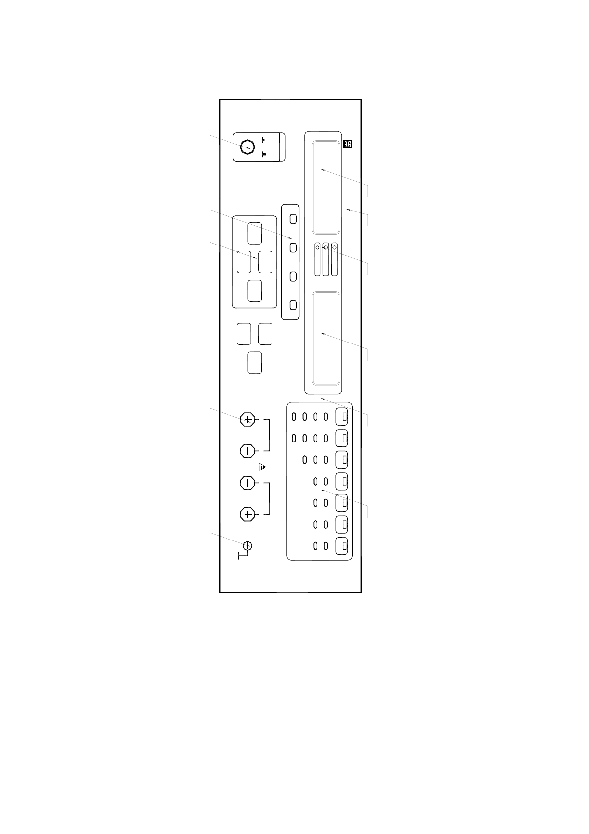
The schematic drawing of the front panel can be seen on the next page (taking
TH2810B LCR Meter as an example).
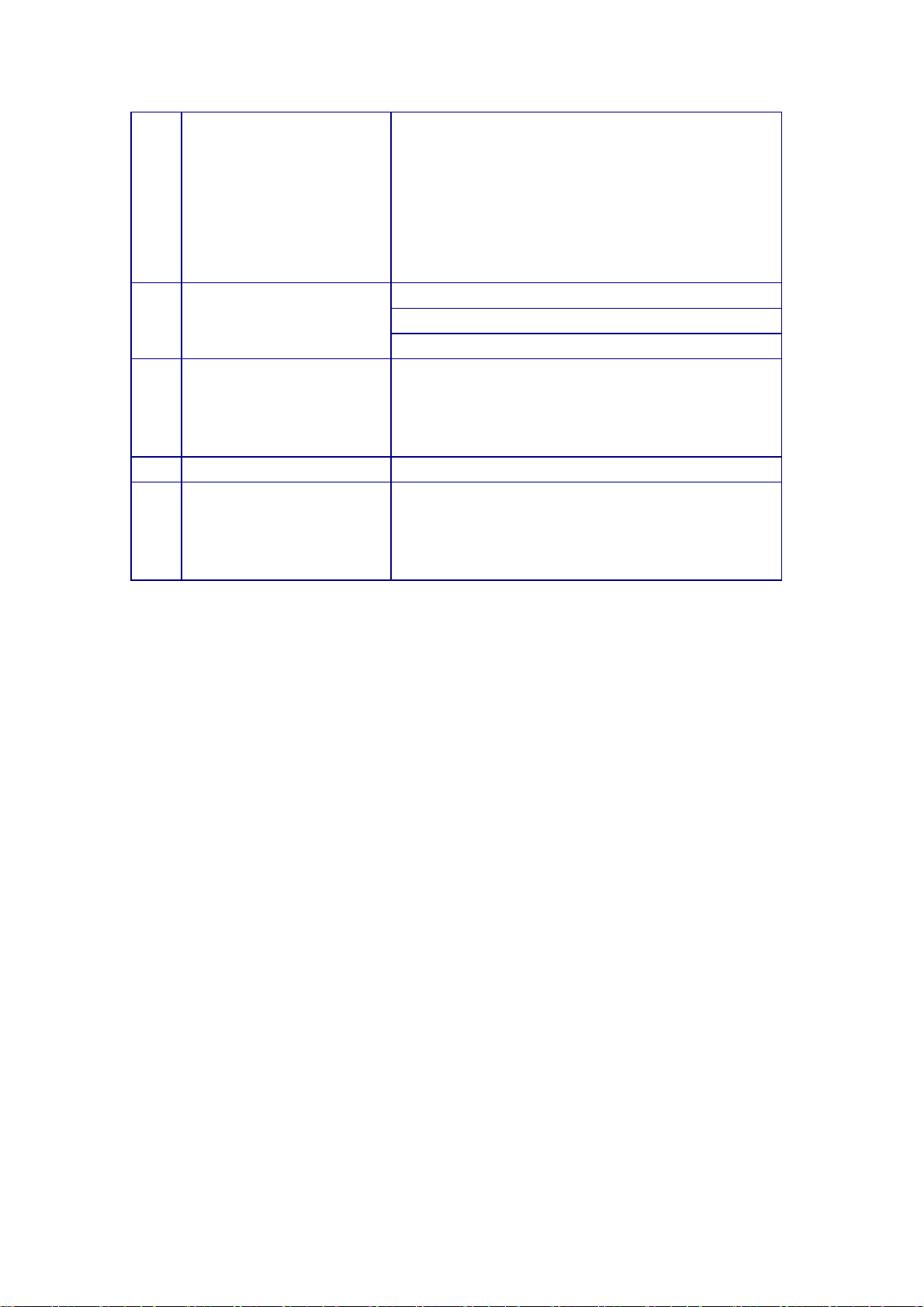
No. NAME FUNCTION DESCRIPTION
to display the measurement values of C, L, Z
Main parameters (or
1
Display A in this
manual)
Units of main
2
parameters
Sub parameters (or
3
Display B in this
manual )
4
5 State indication Refer to §2.1 on P2-1.
6 Frame terminal (GND)
7 Test terminals
and R. Two display modes are available:
direct, and percent deviation %. It can also △
display information when parameters are
being set.
to indicate the units of main parameter in
direct mode
to display the measurement values of D and
Q. It can also display information when
parameters are being set.
to be used for measurements that requires
guarding. The Frame Terminal is tied to the
instrument’s chassis, and it is connected with
the protective earth ground of power supply.
to provide 4-terminals for measurement of
component:
HD (High Drive of current): Test signal is
output through HD. Voltage, frequency and
waveform of test signal can be measured at
HD by voltmeter, frequency meter and
oscillograph, etc.
HS (High Sense of voltage): sample the high
potential of the device under test.
LS (Low Sense of voltage): sample the low
11
Page 12
potential of the device under test.
LD (Low Drive of current): the current flowing
through the device under test is sent to the
current measuring part of instrument.
HD and HS should be connected to one lead of
the device under test and LD and LS should be
connected to another lead.
TH2810B LCR meter
Trade mark of Tonghui
8
& model
TH2618B capacitance meter
TH2775B inductance meter
All the function statees of the instrument can
9 Keyboard
be selected and controlled through the
7-button keyboard (referring to §2.1 on
P2-1).
10 Sorting indication to indicate the sorting result
Power ON/OFF Switch. In ON position, all
11 Power ON/OFF
operating voltages are applied to the
instrument. In OFF position, no operating
voltages are applied to the instrument.
Table 1-6. Front Panel Description
12
Page 13
11 10 9 7 6
ON
POWER
OFF
DISPLAY A DISPLAY B
PASS
P1 P2 P3 NG
ELECTRONICS
TONGHUI
TH2810B
1 2 3 4 58
LCR METER
HI
LO
μH
mH
H
μ
nF
pF
F
MΩ
k
Ω
Ω
D/QNG
PARA
Z-Q
100Hz
HSHD
UNKNOWN
!
LS
LD
L-Q
R-Q
C-D
120Hz
10kHz
1kHz
FREQ
LEVEL
0.3V
0.1V
1V
DISP
DIR
△%
RANGE
AUTO
HOLD
SPEED
FAST
SLOW
Figure 1-2. Front Panel Overview
13
SHORT
CLEAR
OPEN
Page 14
Chapter 2 Operation instruction
This chapter provides detailed description of all functions of the instrument and
operation instruction.
2.1 Keyboard and functions introduction
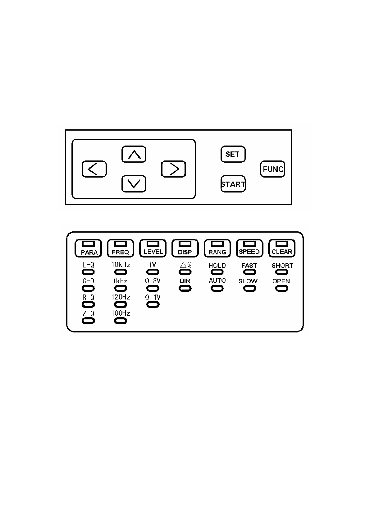
Figure 2-1.Keyboard Overview
Figure 2-2.Status Indicator
TH2810B has 7 keys, and all of them have different functions in different
conditions without direct definition. Each menu will be discussed in this chapter:
The normal state is “measurement” state without pressing “FUNC” or “SET” key;
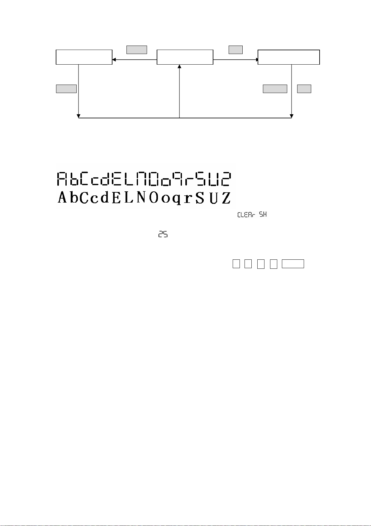
and after pressing “FUNC” key, it is “inner function” state; and “parameter
setup” state after pressing “SET” key. And the conversion of these states is
shown in next figure.
14
Page 15
FUNC SET
Inner function Measurement
Parameter setup
FUNC START SET
Figure 2-3. Status Conversion and Keys
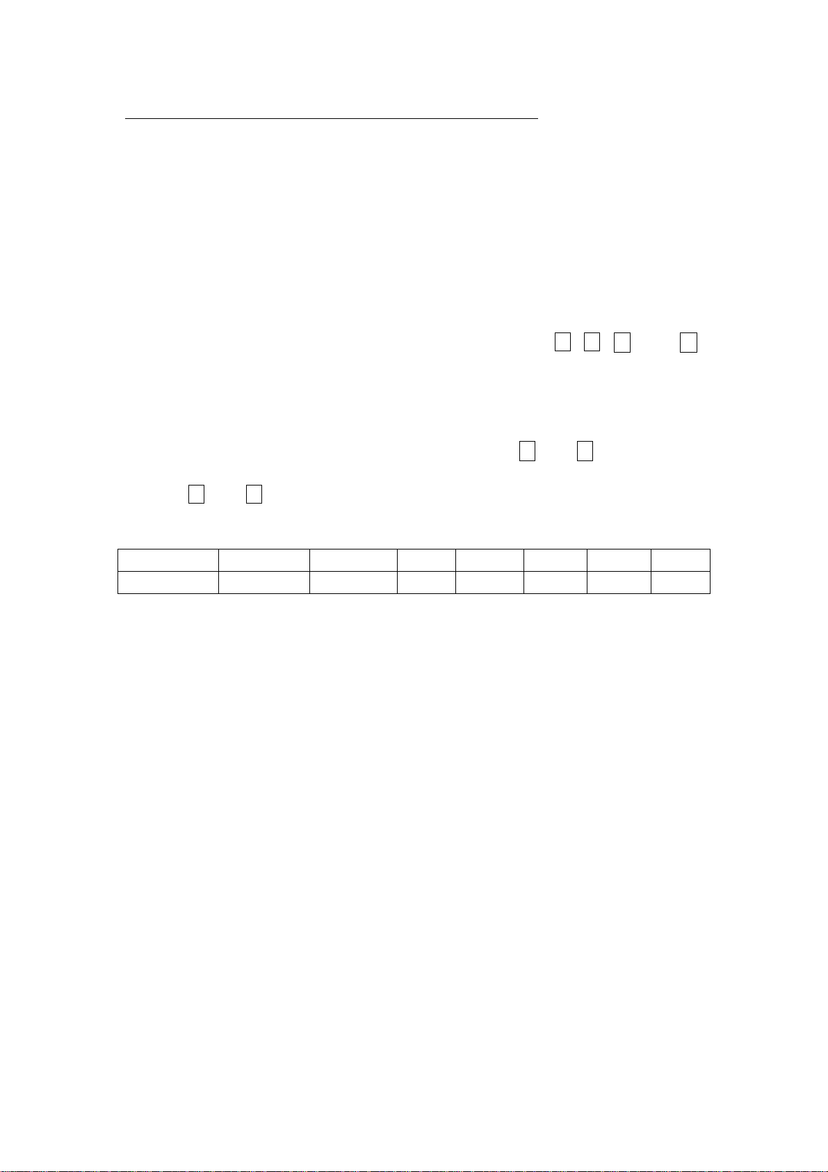
Note: some characters are displayed on display window, while some
corresponding letters show in parenthesis in the manual. And the
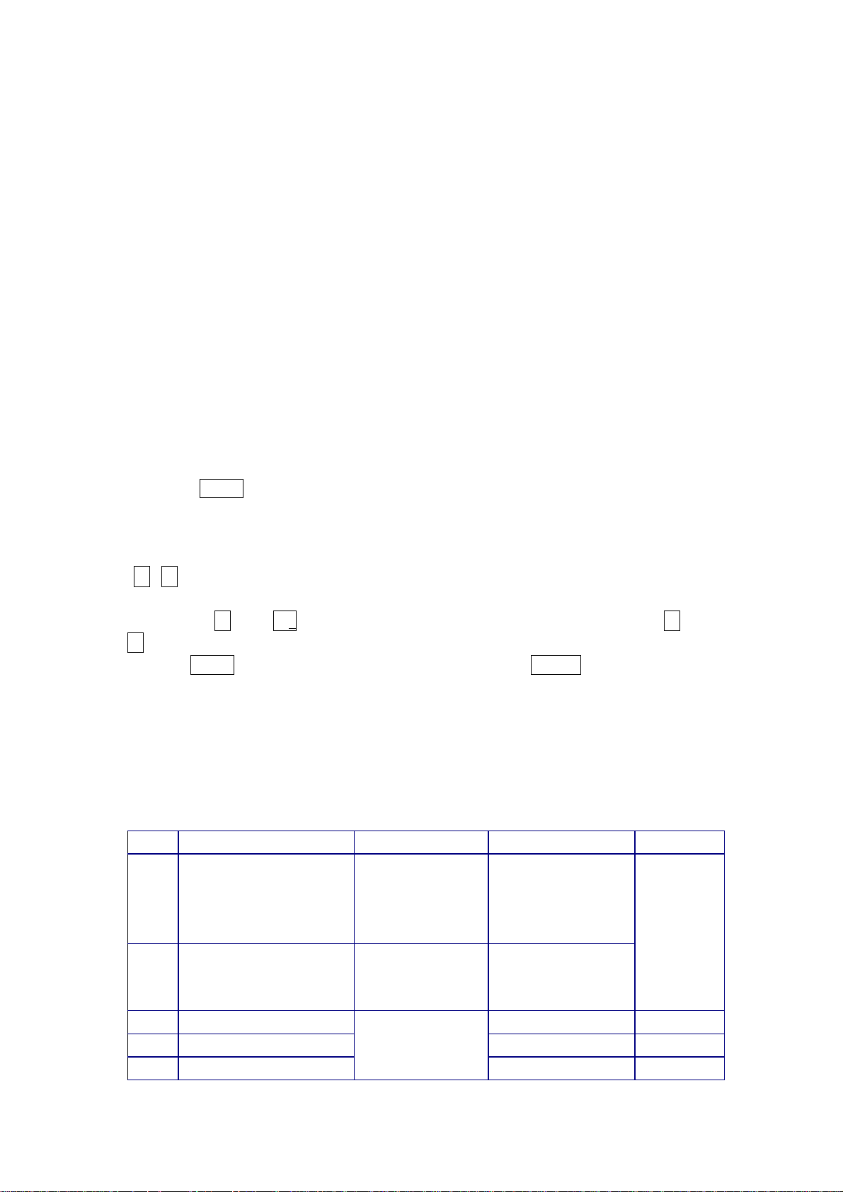
correspondence of letters and characters is shown in the following table:
For example: When performing short correction,
is displayed,
indicating “CLEAr SH”.
When setting reference value, is displayed, indicating “ZS”, not “25”.
1. “measurement” state: Functions are directly indicated on panel, as shown in
Figure 2-2, and corresponding seven commonly-used functions can be
controlled by operating the following cursor keys, ∧, ∨ , <, > , START.
A. Measurement parameter: L/Q, C/D, R/Q, Z/Q, Z/D
B. Measurement frequency: 10 kHz, 1 kHz, 120 Hz, 100 Hz
C. Test signal level: 1.0V, 0.3V, 0.1V
D. Display mode: DIR (Direct) and % (Percent△ deviation) in display A
E. Range mode: HOLD & AUTO
F. Measurement speed: FAST & SLOW
G. Clear (CLEAr): SHORT & OPEN
2. “inner function” state: seven inner functions are available:
A. Alarm (1--bEE): OFF & ON
B. Trigger (measurement mode) (2--ONE): OFF (continuous) & ON (single)
C. Equivalent mode (3--EqU): series (SEr) & parallel (PAr)
D. Sending is allowed through serial interface (4--rSC): OFF (only receiving
allowed) & ON (both receiving and sending allowed)
E. Sorting mode (5--Sor): P1 & P3
F. Signal source resistance (6--rES): 30Ω & 100Ω
G. Key lock (7--Loc): OFF & ON
3. “parameter setup” state: sorting parameters and limits can be set.
A. Reference value setup: LS, CS, RS, ZS
B. High limit of dissipation setup (d
C. High limit of Bin 1 (P1
D. Low limit of Bin 1 (P1
-
)
)
-
-
), or low limit of quality factor setup (q-)
15
Page 16
The following parameters are only displayed in P3 mode
-
E. High limit of Bin 2 (P2
F. Low limit of Bin 2 (P2
G. High limit of Bin 3 (P3
H. Low limit of Bin 3 (P3
)
)
-
-
)
)
-
And it is introduced how to realize each function as follows.
2.2 Function conversion in “measurement” state
Function indications in “measurement” state are shown in Figure 2-2 on P2-1.
All functions can be set through the four cursor keys, ∧, ∨, <, and > .
Functions in each state include items of function and parameter. For example,
“measurement parameter” and “measurement frequency” are function items;
“L/Q”, “C/D”, “R/Q”, “Z/Q” are parameters corresponding to “measurement
parameter”; and “100 Hz”, “120 Hz”, “1 kHz”, “10 kHz” are parameters
corresponding to “measurement frequency”. Operate < and > cursor keys to
select some function item and the corresponding indicator lamp is on; and then
operate ∧ and ∨ cursor keys to select parameters in the function and the
corresponding indicator lamp is on.
The default functions in “measurement” state are shown in Table 2-1.
function parameter frequency
parameter C-D
NOTE
1kHz 1.0V direct auto slow open
Table 2-1.The Default Functions in “measurement” State
NOTE: The default parameter of TH2775B is L-Q.
level display range speed clear
2.2.1 Measurement parameters
The optional measurement parameters of TH2810B are shown in Table
1-1.Measurement parameters table on P1-2.
L/Q: inductance L & quality factor Q;
C/D: capacitance C & tangent of dissipation angle D;
R/Q: resistance R & quality factor Q;
R/D: resistance R & tangent of dissipation angle D;
Z/Q: impedance Z & quality factor Q.
Parameters L, C, R, and Z are displayed in Display A, and D and Q in Display B.
The parameter units are as follows:
3
L: µH, mH and H, 1 H=10
C: pF, nF and µF, 1 µF=103 nF=106 pF;
R, Z: Ω, kΩ and MΩ, 1 MΩ=103 KΩ=106 Ω
Z, D and Q have the same measurement values in series or parallel equivalent
circuit, while L, C and R have different measurement values in different
equivalent circuits. The relation of the two equivalent circuit modes is shown in
Table 2-4 Conversion between circuits of series and parallel connection on
P2-11.
mH=106 µH;
16
Page 17

Z displayed in Display A is always positive (≥0). C, L and R may have negative
values. When measuring C & D, the negative value of C means that the
component under test has the characteristics of an inductor. When measuring
L&Q, the negative value of L means that the component under test has the
characteristics of a capacitor. In theory, the resistance of has the positive value.
However, in some cases, value of R may be negative, which is generated due to
excess correction. In order to eliminate the negative value of R, correct
corrections are needed.
Sub parameter D is the reciprocal of Q, that is, D=1/Q.
2.2.2 Measurement frequency
Different components need signals with different measurement frequencies to
measure. For example, electrolytic capacitor usually needs 100 Hz and120 Hz to
measure, and metalized film capacitor needs 1 kHz or 10 KHz. It depends on
real-world needs.
TH2810B provides four measurement frequencies: 100 Hz, 120 Hz, 1 kHz, and
10 kHz.
2.2.3 Test signal level
TH2810B provides three test signal levels available: 1 V, 0.3 V, and 0.1 V.
An inductor’s inductance value may differ widely depending on the current
through the inductor due to the permeability of its core material. Usually, high
test level is used for normal test of components (such as capacitor, resistor and
some kind of inductor), and low test level is used for those components which
work in the circuit of low level (such as semiconductor device, output impedance
of battery, inductor and nonlinear impedance component). For some devices,
the measurement values differ widely depending on the measurement level, for
example inductor components. And the voltage level actually applied across the
device may be different with the set value, refer to §2.3.6 Signal source
resistance.
2.2.4 Display mode
TH2810B provides two modes: direct and % (percentage deviation).△
2.2.4.1 Direct
In DIR mode, the measurement values displayed in Display A have their
corresponding units. The following units are used by the instrument:
3
L: µH, mH and H, 1 H=10
C: pF, nF and µF, 1 µF=10
R, Z: Ω, kΩ and MΩ, 1 MΩ=10
In DIR mode, when DUT hasn’t been connected, in the state of L, R, and Z, there
should be a large variable number displaying in Display A, which is even beyond
display range to be no display. And D/Q value in Display B is a variable number.
mH=106 µH;
3
nF=106 pF;
3
KΩ=106 Ω
17
Page 18
2.2.4.2 %△
X
X
nx
=Δ
The formula is:
and Xn is the set nominal value.
Because it takes a while to complete deviation calculation at the time of
measurement, the measurement speed slows a little.
Nominal value must be set before deviation measurement, because the
absolute deviation is the difference between the measured value of the
component and a previously set nominal value. And it has both magnitude and
unit. Please refer to §2.4 Parameter setup method to set nominal value.
In this mode, positive and negative values display in percentage mode with the
least resolution of 0.01%.
Incorrectly set nominal value leads to invalid % display. If nominal value is set △
to be 0, % will become infinite, which is beyond display range to make no △
display in Display A.
−
X
n
%100% ×
, in which Xx is measured value,
2.2.5 Range mode
2.2.5.1 Range definition and its range
TH2810B has five basic ranges and one extensional range. There is a cross
between two neighboring ranges. When measurement range is set to AUTO, the
instrument will judge if the optimum measurement range is selected after each
measurement. If the range is the optimum range, the instrument calculates and
displays the measurement value; otherwise the instrument should adjust the
measurement range and measure again. So in AUTO mode, more time will be
added to select the optimum measurement range and adjust the measurement
range.
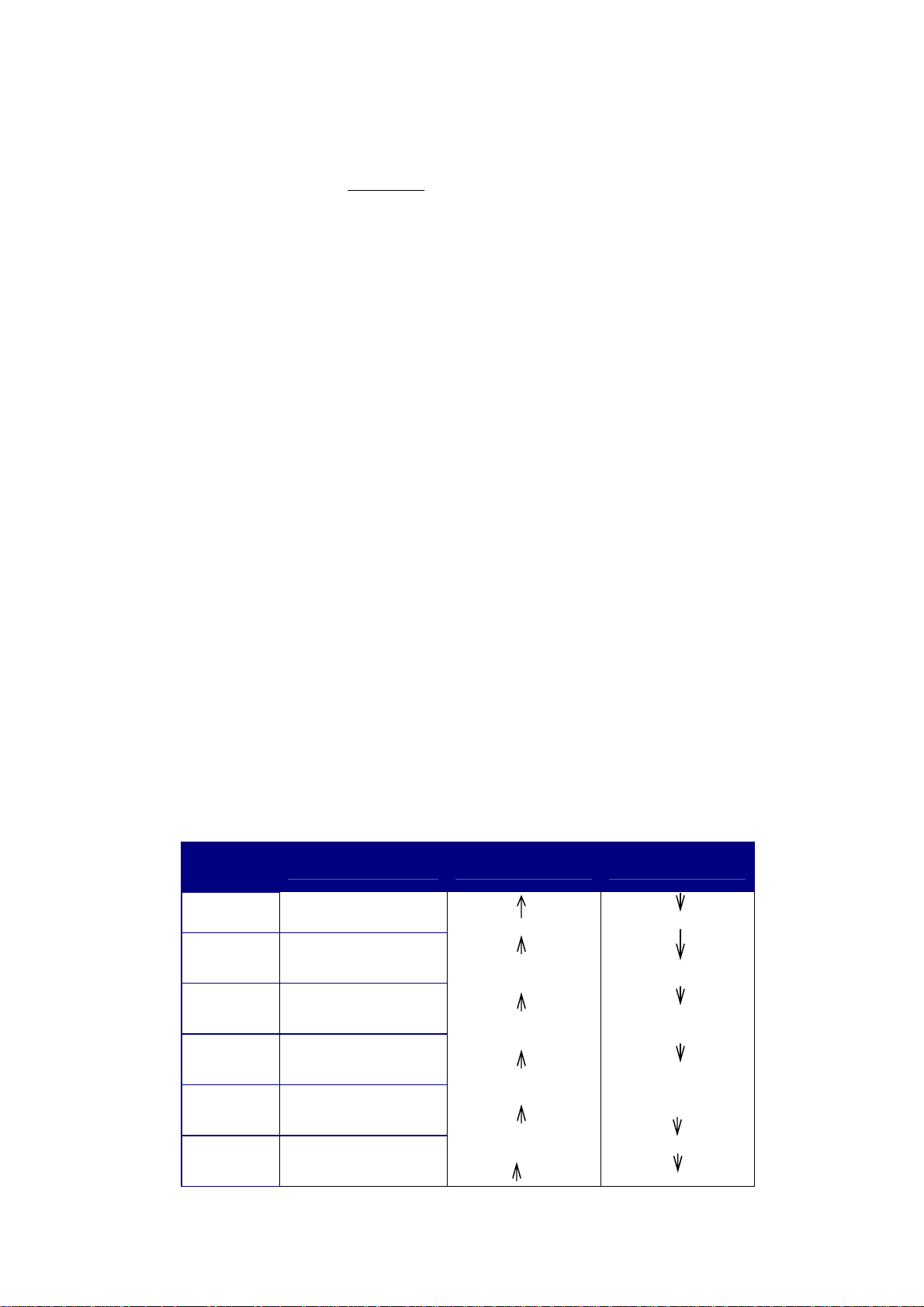
Range
No.
0
1
2
3
4
Range Range up Range down
100kΩ
10kΩ
1kΩ
100Ω
31.6Ω
95kΩ 90kΩ
9.5kΩ 9kΩ
950Ω 900Ω
95Ω 90Ω
5
(extensional)10Ω
12Ω 11Ω
18
Page 19

Table 2-2.Range No., Range Resistance and Range Adjustment
From Table 2-2, there is a cross of 5% between two neighboring ranges, instead
of an absolute dividing limit. And the cross can avoid range’s frequent
jumpiness when the impedance is right at the dividing limit, and the range
doesn’t vary. For example, Zx = 920 kΩ, it will be measured in Range 2 or
Range 3.
According the test frequency, capacitance, or inductance, the range of the
capacitor or the inductor can be calculated.
For example: C = 0.22 µF, D = 0.0010, measurement frequency f = 10 kHz,
then
1
+=
RZ
XX
Z
X
2
π
1
fC
π
fCj
2
X
=≈
π
X
1
−
63
××××
1022.010102
Ω=
37.72
From Table
2-3, the optimum range of this capacitor is Range 4.
2.2.5.2 Range Hold
When the components to be measured have the same nominal, we can set the
range mode to HOLD to increase the measurement speed. When in HOLD mode,
the instrument will not spend any time selecting the range. Perform the
following steps to select the optimum range:
1. Press < or > key to select the function of RANGE;
2. Make sure that the range mode is in AUTO state;
3. Connect one of the components to the fixture;
4. Set the range mode to HOLD using ∧ or ∨ key after the measurement value
is stable.
If the impedance of DUT is out of the effective measurement range of the held
range, TH2810B’s measurement accuracy does not meet its specification. So
make sure that the optimum range is selected when using the range hold
function.
2.2.6 Measurement speed
TH2810B provides two measurement speeds: fast and slow. When the range is
set to AUTO, measurement time needs to increase range adjustment time, and
when the range is not correct, range adjustment time and another
measurement time need to be increased.
Measurement Time
The measurement time consists of two main parts: integration time and
calculation time.
The sum of integration time and calculation time determine the measurement
speed.
The calculation time is about 25 ms;
19
Page 20

Integration time in fast speed: approx. 30 ms;
Integration time in slow speed: approx. 180ms;
So approximate speeds can be calculated:
Fast speed: approx. 15times/sec.
Slow speed: approx. 4.5times/sec.
2.2.7 Clear (Correction)
In order to maintain high measurement accuracy, SHORT and LOAD corrections
for correcting the stray admittance, the residual impedance, and the other
errors can be performed. OPEN clear and SHORT clear are provided by TH2817.
When TH2810B performs OPEN/SHORT correction, all ranges with different
measurement speeds, frequencies, levels are cleared once. And all the clear
parameters are saved in nonvolatile RAM inside the instrument. It’s not
necessary to clear “0” again when restarting instrument. When measurement
environment changes, such as temperature, humidity, test fixture, and space
between down-leads, another OPEN/SHORT correction should be performed.
z OPEN correction
1. Press < or > key to select the function of CLEAR;
2. Press ∧ or ∨ key to select OPEN parameters, and “CLEAr” and “OP” are
displayed. If clear operation is not needed, press < or > key to exit.
3. Make sure the test terminals are absolutely open.
4. Press START key to perform open correction. Then, the function item
automatically alters to PARAMETER to exit.
z SHORT correction
1. Press < or > key to select the function of CLEAR;
2. Press ∧ or ∨ key to select SHORT parameters, and “CLEAr” and “SH” are
displayed. If clear operation is not needed, press < or > key to exit.
3. Use TH26010 short-circuit slice or conducting line of low resistance to make
the test terminals absolutely short.
4. Press START key to perform short correction. Then, “CLEAR” parameter
alters to “OPEN”, and the function item automatically alters to PARAMETER
to exit.
Note: When performing open or short correction, if the test terminals are not
absolutely open or short as the manual describes, “FAIL” will be displayed in
Display A, and the instrument makes short time alarm, which tells that because
correction fails in this condition, the instrument can’t save all the correction data
and it will exit.
In order to make reliable correction, following rules should be observed:
1. Keep the same condition of the conducting line with that when the correction
is performed;
2. When short correction is performed, shorting plate supplied by the
instrument or conducting line of low resistance, should be used to make test
terminals short. Don’t directly connect HD and HS, LD and LS. Keep HD and HS,
LD and LS not being directly connected after inserting conducting line of low
20
Page 21
resistance when test fixtures are used to make short. And HS and LS can be
directly connected.
Note: If the test terminals are not absolutely open or short, the instrument’s
operation performance is probably affected by incorrect clear parameters after
correction.
2.3 Conversion of “inner function” state
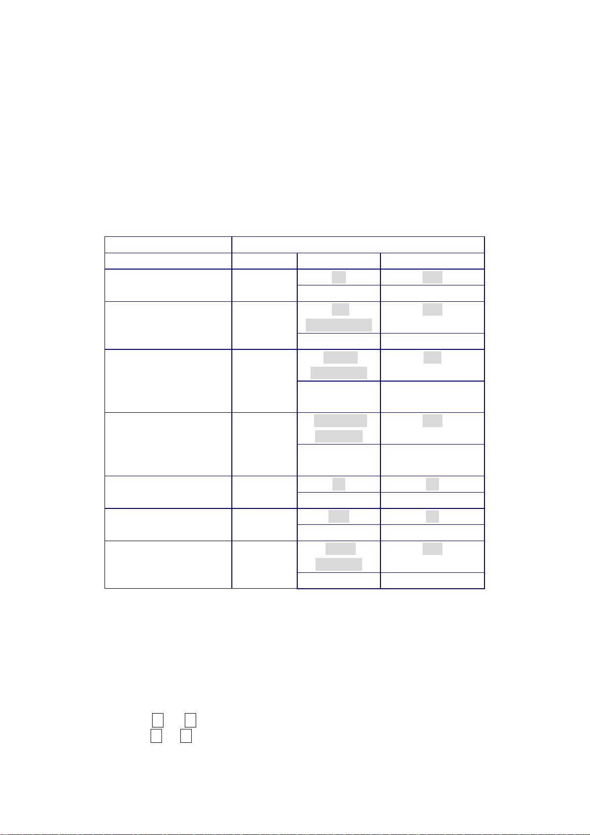
There are seven functions in “inner function” state shown in Table 2-3.
Function Parameter
Name Display A
2―ONE
(measurement
mode)
6―rES
resistance
Table 2-3 Parameters in “inner function” State
Name Display B
off OFF Alarm 1―bEE
on ON
off
(continuous)
on (single) ON
series
connection
parallel
connection
off – only
receiving
0n – receiving
& sending
P3 P3 Sorting mode 5―Sor
P1 P1
30Ω
100Ω
off --
unlocked
on -- locked ON
OFF Trigger
SEr Equivalent mode 3―EqU
PAr
OFF Serial interface 4―rSC
ON
30 Signal source
100
OFF Key lock 7―Loc
Note: Parameter setup in shadow is default state.
As Figure 2-3 on P2-2 shows, at the state of “measurement”, press FUNCTION
key once to enter the state of “inner function”. Perform the following steps to set
function parameters:
1. After selecting “inner function” state, selected function is shown in
Display A, and parameter of the function in B;
2. Use < or > key to select some function item;
3. Use ∧ or ∨ key to select parameter of the function;
4. Repeat the above operations to select parameters of all functions;
21
Page 22

5. Press FUNCTION key to exit.
2.3.1 Alarm
The default setting is “OFF”, which means no alarm.
When “ON” is selected, and the sorting result is “P1” or “PASS”, the beeper
alarms.
Only if the sorting parameter is correctly set to get correct sorting result signal,
correct alarm signal can be obtained.
2.3.2 Trigger (continuous/single)
The default setting is “OFF”, which means continuous measurement. In this
mode, the instrument continuously measures and calculates display value. And
after one measurement, another measurement immediately starts.
If “ON” is selected, which means single measurement, the instrument doesn’t
start one measurement until getting ‘START” signal. The signal can be obtained
through either START key on front panel or HANDLER interface, RS-232C
interface.
2.3.3 Equivalent model
The default model is serial connection (“SEr”).
The real-world capacitor, resistor and inductor are not ideal, but component of
complex impedance in the form of serial connection or parallel connection. The
instrument calculates necessary values according to equivalent circuit
connected in series or parallel. And different result will be obtained in different
circuits, differing in different components.
The following description gives some practical guide lines for selecting the
equivalent circuits:
1. Real-world equivalent circuit can be selected following the manufacturer’s
recommendation. If there is no recommendation to be followed, we select the
circuit mode according to the variation of D under two different frequencies. If
the dissipation factor of a capacitor increases with the increase of the test
frequency, series circuit mode will be selected. In formulas in following table, D
in series connection is in direct ratio with frequency. If the dissipation factor
decreases with the increase of the test frequency, parallel circuit should be used,
and D in parallel connection is in inverse ratio with frequency. For inductor, the
situation is just in the opposite side.
2. Judge according to the actual application in circuits. If a capacitor is used as
a coupling capacitor, series circuit mode is the best choice; if a capacitor is used
in a LC oscillator then parallel circuit model can be selected.
3. Select the equivalent circuits according to the following rules:
Component with low impedance (such as large capacitor and small inductor) is
usually measured in series circuit mode;
Component with high impedance (such as small capacitor and large inductor) is
22
Page 23
usually measured in parallel circuit mode;
Normally, when |Zx| < 10Ω, the series circuit mode is selected;
When |Zx| >10kΩ, the parallel circuit mode is selected;
When 10Ω<|Zx| <10kΩ, follow the manufacturer’s recommendation.
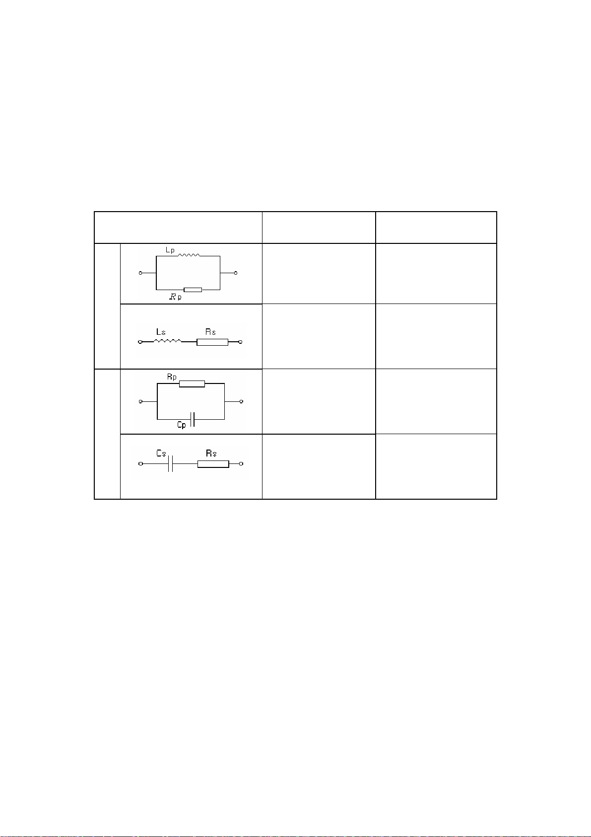
Two equivalent circuits can be conversed through some formula, and Q and D
don’t change in different circuits, as shown in table 2-4, where s means series
connection, p means parallel connection.
Q=Xs/Rs, D=Rs/Xs, Xs=1/2πFCs=2πFLs
Circuit model Dissipation (D)
D=2πFLp/Rp=1/Q
Equivalent model
conversion
2
Ls=Lp/(1+D
)
Rs=RpDP2P/(1+D
2
)
L
2
D=Rs/2πFLs=1/Q
Lp=(1+D
Rp=(1+D
)Ls
2
)Rs/D2
D=1/2πFCpRp=1/Q
Cs=(1+D2)Cp
Rs=RpDP2P/(1+D
2
)
C
2
D=2πFCsRs=1/Q
Cp=Cs/(1+D
Rp=Rs(1+D
)
2
)/D2
Table 2-4 Circuit Model Conversion
2.3.4 Serial interface
The default setting is “OFF”, which means that serial interface is always in the
state of receiving command (unilateralism). When it is set to “ON”, the
instrument sends measurement state and result through interface at the same
time. If “4-rSC ON” is selected, RS-232C interface is opened, which means that
it is allowed to send measurement result through serial interface (bidirectional).
TH2810B’s serial interface meets the RS-232C DB-9 standard. The serial
interface adopts
asynchronous serial communication bus with fixed baud rate of 19200 bit, the
logic level of ±8V and the maximum transmission distance of 15m. The data
format is as follows:
23
Page 24
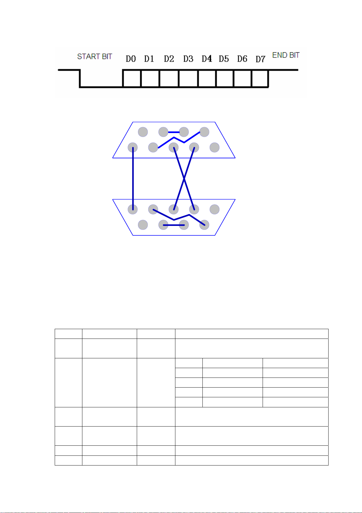
Figure 2-5
Data Format Transmitting through RS232C Serial Interface
6789
GND
TXD
RXD
6789
Hole
12345
12345
Hole
RS232C interface cable
Pin 2: RX
Pin 3: TXD pin, receiving terminal
Pin 5: GND, instrument ground
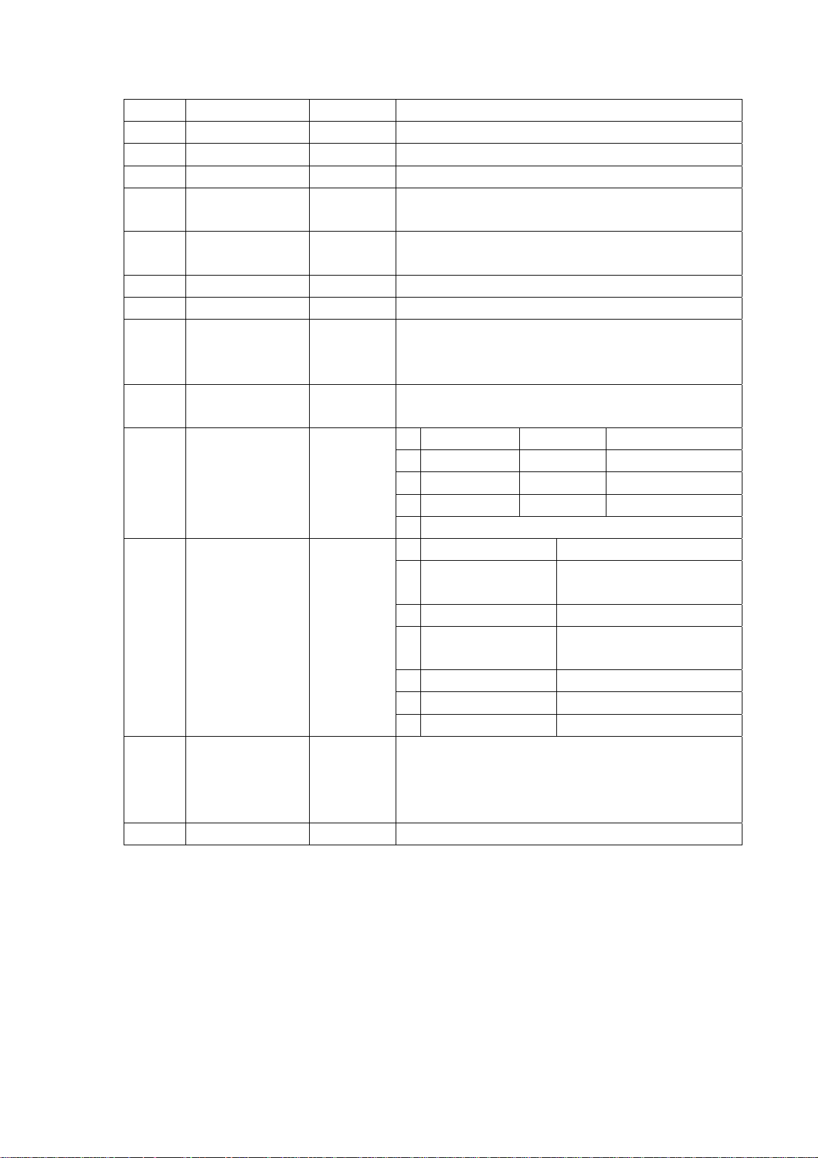
Information transmitted through RS-232C interface is ASCII code. The output
information is listed in Table 2-5 (TH2810B computer).→
D pin, sending terminal
Figure 2-6 RS232C Serial Interface’s Connection with Cable
No. Function Symbol Description
1 start character
{ no special meaning
recognition
2 display of main
0, 1, 2, 3
and sub
parameters
note 1
0
note 2
1
main parameter sub parameter
Inductance (L) quality factor (Q)
capacitance (C) dissipation (D)
2 resistance (R) quality factor (Q)
3 impedance (Z) quality factor (Q)
3 frequency 0, 1, 2, 3 0: 10kHz 1: 1kHz
2: 120Hz 3: 100Hz
4 level 0, 1, 2 0: 1V 1: 0.3V
2: 1V
5 display mode 0, 1 0: percentage deviation 1: direct
6 range 0, 1 0: hold 1: auto
24
Page 25
7 speed 0, 1 0: fast 1: slow
%
8 clear 0, 1 0: short 1: open
9 beeper 0, 1 0: on 1: off
10 trigger mode 0, 1 0: continuous 1: single
11 equivalent
0, 1 0: serial connection 1: parallel connection
model
12 serial interface 0, 1 0: off (only receiving)
1: on (receiving and sending)
13 sorting mode 0, 1 0: P1 1: P3
14 impedance 0, 1
15∼20
main
parameter
0~9, “.”,
“-”
0: 30Ω 1:100Ω
from high digit to low digit
data
21∼26
sub parameter
data
27 unit of main
parameter or
%
0∼9, “.”,
“-”
0, 1, 2, %
from high digit to low digit
L-Q C-D R/Z-Q
0 uH pF
1 mH nF
2 H uF
percentage deviation
28 sorting output 0, 1, 2, 3,
4, 5
P3 P1
0 NG (not
qualified)
D/QNG (sub parameter
is more than limit)
1 P1 (first-class) PASS (pass)
2 P2
(second-class)
HI (more than high
limit)
3 P3 (third-class) LO (less than low limit)
29 current range 0, 1, 2, 3,
4, 5
4
5
five following ranges:
0: 100kΩ 1: 10kΩ
D/QNG & HI
D/QNG & LO
2: 1kΩ 3: 100Ω
4: 31.6Ω 5v10Ω
30 end bit } no special meaning
Table 2-5 Format of Serial Data Transfer
Ω
kΩ
MΩ
Note 1: In Th2618B: resistance (R) & dissipation (D)
Note 2: In Th2775B: resistance (R) & quality factor (Q)
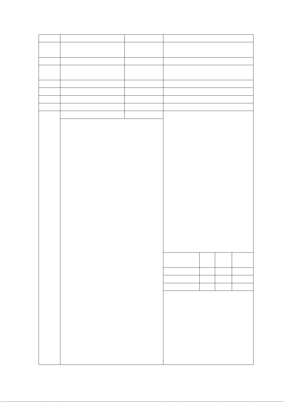
The control command of TH2810B serial interface is listed in Table 2-6
(computer TH2810B, in the fo→ rm of ASCII code).
In the following table, each command can only be sent alone, and you are not
allowed to send more than two commands once. Each command starts with
{ and ends with }. Command with wrong format can’t change corresponding
function, and will be dealt with as invalid command by the instrument. It’s
25
Page 26
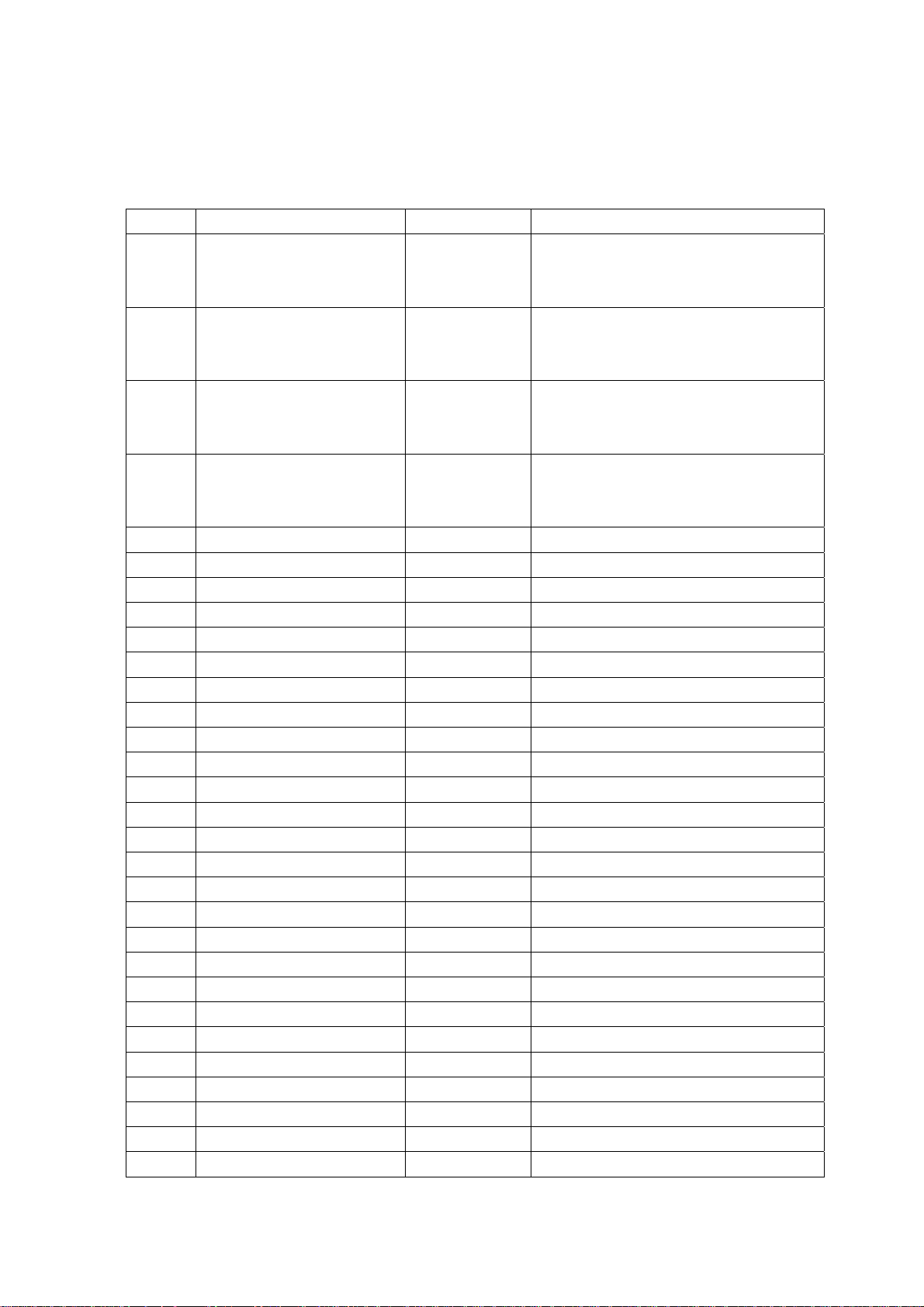
suggested that limit parameter and nominal value be input according to the
format requirement after the instrument is adjusted, in order to avoid being
dealt with as invalid command.
No. Command code
Note 1
1
A0 2 measurement parameter & series
Note 0
Characters
Function
connection and parallel
connection: L-Q
Note 2
2
A1 2 measurement parameter & series
connection and parallel
connection: C-D
3 A2 2 measurement parameter & series
connection and parallel
connection: R-Q
4 A3 2 measurement parameter & series
connection and parallel
connection: Z-Q
5 B0 2 measurement frequency: 10 kHz
6 B1 2 measurement frequency: 1 kHz
7 B2 2 measurement frequency: 120 Hz
8 B3 2 measurement frequency: 100 Hz
9 C0 2 measurement level: 1 V
10 C1 2 measurement frequency: 0.3 V
11 C2 2 measurement frequency: 0.1 V
12 D0 2 display mode: % △
13 D1 2 display mode: direct
14 E0 2 range: holding at current range
15 E1 2 range: auto
16 E2 2
17 E3 2
18 E4 2
19 E5 2
20 E6 2
21 E7 2
range: holding at 0 (100 kΩ)
range: holding at 1 (10 kΩ)
range: holding at 2 (1 kΩ)
range: holding at 3 (100 Ω)
range: holding at 4 (31.6 Ω)
range: holding at 5 (10 Ω)
22 F0 2 measurement speed: fast
23 F1 2 measurement speed: slow
24 G0 2 short correction
25 G1 2 open correction
26 H0 2 alarm: (ON) to turn on beeper
27 H1 2 alarm: (OFF) to turn off beeper
28 I0 2 trigger: (Off) continuous
29 I1 2 trigger: (Off) single
30 J0 2 equivalent model: (SER) serial
26
Page 27
connection
31 J1 2 equivalent model: (PAR) parallel
connection
32 K0 2
33
K1 2
RS232A口: (OFF) only receiving
RS232A口: (ON) receiving and
sending
34 L0 2 sorting mode: P1
35 L1 2 sorting mode: P3
36 M0 2
37 M1 2
38
NX=X1X2BX3X4X5X6X7 ≤10 NX: related set parameters
Example and notes: (symbols used to
express in the examples, and ASCII
code should be used in real-world
program)
1. N1=122 will be automatically
adjusted to N1=12.0002 (7 characters)
after being received by the instrument,
and the last bit is unit code. When
resistance is measured, the nominal
value is 12 MΩ. That is, N1 starts with
number (the first one from 0~9), the
rest being numbers (0~9) and point,
and ends with unit code. The number of
total characters should be less than 7
after automatic adjustment.
2. N2=12 will be automatically
adjusted to N2=12.000 (6 characters)
after being received by the instrument,
that is, N2 (Q/D limit value) starts with
number (the first one from 0~9), and
the rest are number 0~9 and point. The
number of total characters should be
less than 6 after automatic adjustment.
3. N3=1% will be automatically
adjusted to N3=+1.000% (7
characters) after being received by the
instrument, that is, N3~N8 (limit
value) starts with symbols or numbers.
If starting with symbol, the second
character should be number, the rest
being number 0~9 and point, and ends
with %. The total characters should be
signal source resistance: 30Ω
signal source resistance: 100Ω
Parameter values and units are
after “=”.
The regulations are as follows:
N1: nominal value N2: Q/D limit
value
N3: first-class high limit N4:
first-class low limit
N5: second-class high limit N6:
second-class low limit
N7: third-class high limit N8:
third-class low limit
Data format is as follows after
being received and adjusted:
1. N1: X1: ASCII code (0∼9);
: ASCII code (0~9 and
X
2∼X6
point);
X
: ASCII code (0∼2) (unit code)
7
Definition of X
X7’s ASCII
code
30H pF
31H nF mH
32H
is as follows:
7
C L Z, Q
μH Ω
KΩ
μF
H
MΩ
2. N2: X1: ASCII code (0∼9);
: ASCII code (0~9 and
X
2∼X6
point);
3. N3∼N8:
X
: ASCII code (+, -);
1
X2: ASCII code (0∼9);
: ASCII code (0~9 and
X
3∼X6
point);
X
: ASCII code (%)
7
less than 7 after automatic adjustment.
27
Page 28

39 NX=?
Note 3
4 The instrument sends
corresponding setting value once
after receiving the command that
setting value is inquired. Sending
format: {NX=X
1X2X3X4X5X6X7
}.
Refer to command 38 Data format
regulation after being received
and adjusted.
40 P0 2 start, the same function as START
key.
Table 2-6. Format of Serial Command
Note 0: “Command code” should be in the form of ASCII code in the real-world
program. Such as, {0} can be recognized by its ASCII code, 7B41307D.
Note 1: In TH2618B: resistance (R) & dissipation (D).
Note 2: In TH2775B: resistance (R) & quality factor (Q).
Note 3: Defined reference command of NX is 38.
The controller sends continuous command program: sending command 1 —>
the function of making sure that data the instrument sends back are received
has been altered correctly —> sending command 2 again. Recycle these
operations till all the functions are correctly altered.
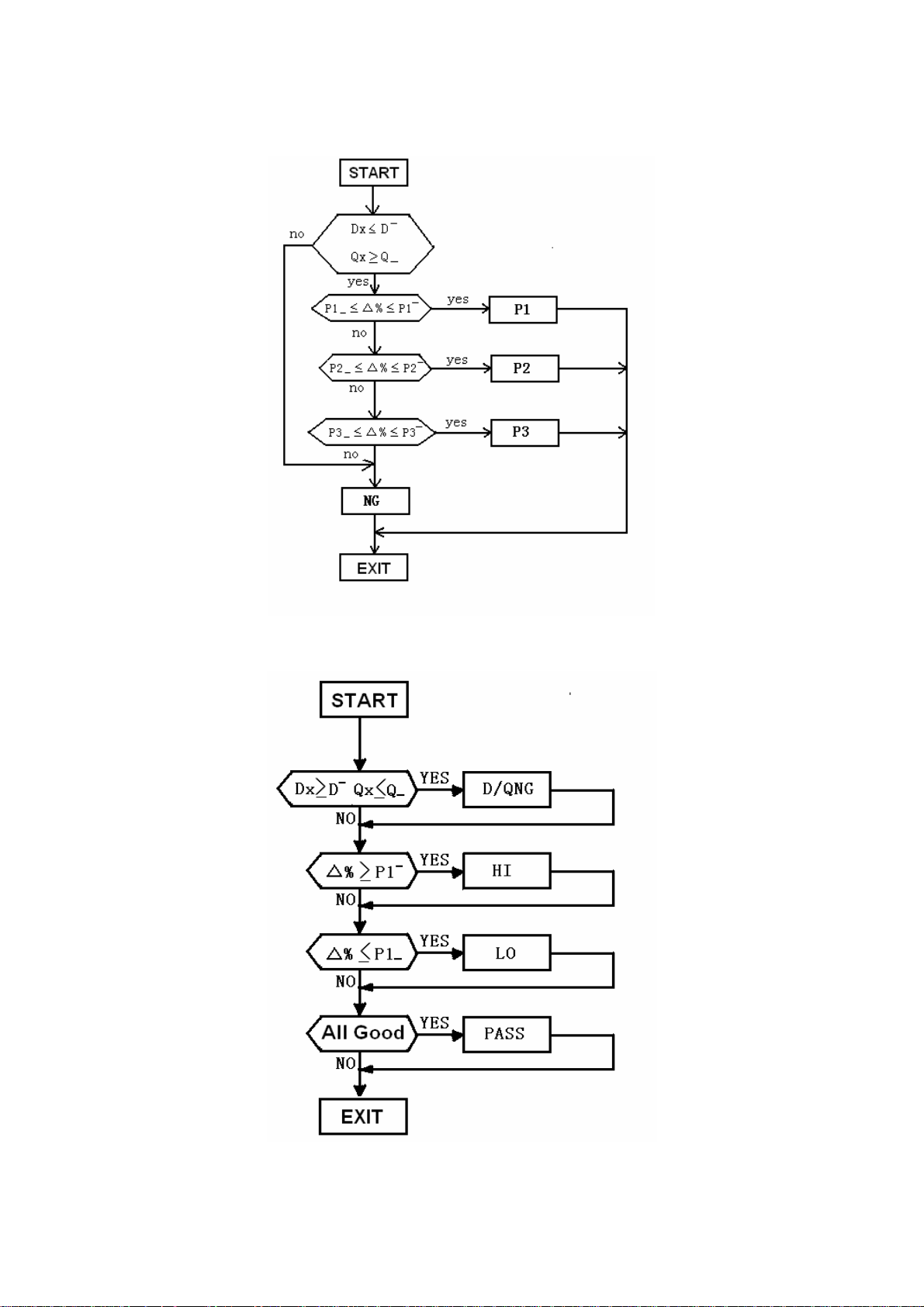
2.3.5 Sorting mode
Th2810B provides two sorting modes: P3 (default mode) and P1, which are
valid in both direct and Δ% display modes.
28
Page 29
2.3.5.1 Sorting procedure
Figure
2-7 Sorting Procedure in P3 Mode
Figure
2-8 Sorting Procedure in P1 Mode
29
Page 30
As shown in above figures, P3 sorting mode is suitable for sorting multi-bin,
where only one of P1, P2, P3 and NG signals is valid. When one of P1, P2, P3
signals is valid, sub parameter must be qualified; and when NG signal is
qualified, probably main parameter or sub parameter is not qualified.
2.3.5.2 Handler interface
Refer to §2.4 Parameter setting method to set main and sub parameters and
nominal value. Then insert the DUT, and the sorting result can be obtained
through the following methods:
z Observe sorting instruction information on panel to tell whether the
component is qualified or not. There are four indicator lamps, which have
corresponding results:
In the state of P3: P1: first-class product P2: second-class product
P3: third-class product NG: not qualified
In the state of P1: PASS: qualified
HI: main parameter is more than high limit
LO: main parameter is less than low limit
D/QNG: sub parameter is not qualified
z If alarm is on (refer to §2.3.1 Alarm), the beeper in the instrument makes
alarm when P1 (PASS) signal is output.
z Handler interface: the precondition is that the instrument must be set to
single mode (refer to §2.3.2). Through this interface, TH2810B can
synchronously work with one component’s auto measurement system. An
outer “START” signal is received through the interface to start measuring,
and four sorting result signals and two synchronous controlling signals are
sent out to control outer machine’s movement structure.
Handler interface is on the rear panel, and its signals are as follows (definitions
in P1 sorting state in brackets):
NG(D/QNG)
1
O201
O202
O203
O204
O205
O206
O207
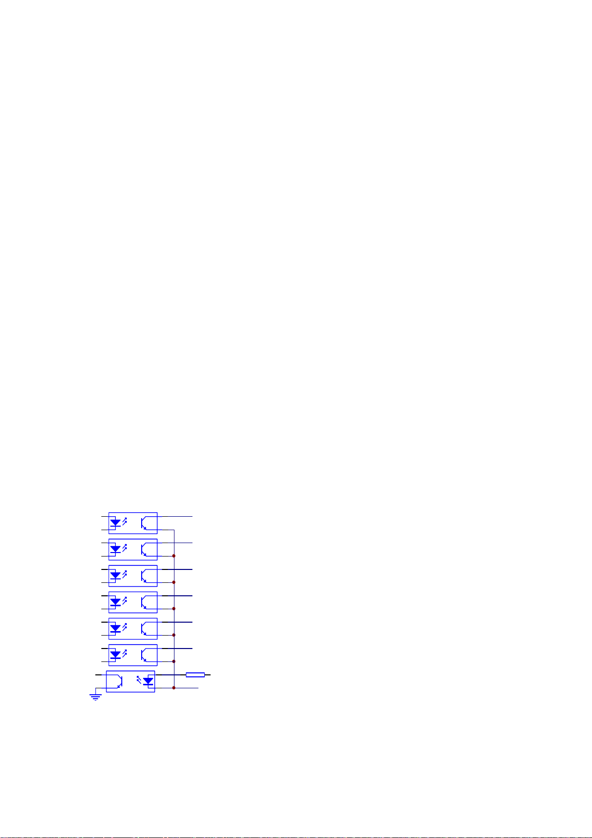
Figure 2-9 Pin of Handler Interface 12mA. If power is 24V, R203 = power/12mA =
P1(PASS)
2
P2(HI)
3
P3(LO)
4
WAIT
5
EOC
6
R203
COM
9
/330
7
START
24V/12mA = 2 kΩ. User can change R203 on main PCB, or serially connect a
resistance of 2 kΩ between outer switch and Pin 7 START. And if power is 12V,
Note:
Because light coupling output signal is
opto-isolated circuit, resistance must be pulled
up so that signal can be output. Current of 25
mA can be absorbed when the signal is low
asserted.
When one sorting result signal is valid,
corresponding light coupling output terminal is
connected. For example: if P1 is valid, light
coupling O202 is connected, and P1 is low
asserted.
Value of R203 (default 330Ω) should drive
O207 into saturation, with the input current of
30
Page 31
the resistance of 1 kΩ should be applied.
Definitions of pins are as follows:
1. Sorting result (NG/DQNG, P1/PASS, P2/HI, P3/LO): output, low-asserted.
2. WAIT (busy): output, high-asserted. This signal can be used to control outer
machine’s operation of dealing with equipment. When the signal is valid, the
instrument is in the state of measurement and calculation.
3. EOC (A/D completion): output, high-asserted. When this signal is output,
the DUT’s measurement (A/D conversion) has completed, but probably the
calculation is still in procession. When the output is low, it must be ensured
that test terminal and the DUT keep good connection. And when it’s high, it’s
allowed to move next DUT to test terminal to prepare for next measurement.
4. START (start): input, rising edge and it’s valid when the maintaining time of
high level is more than 2.5ms. This signal is supplied to HANDLER’s input
terminal from outside.
5. COM: interface’s grounding terminal.
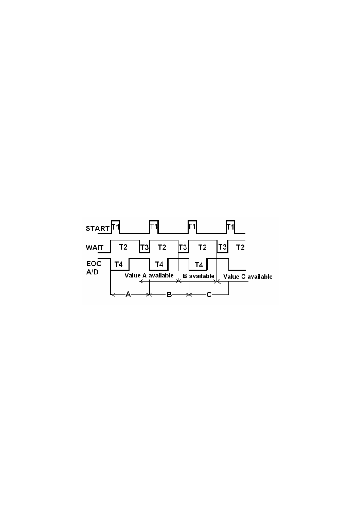
Figure 2-10 shows the timing diagram of the Handler interface. (A, B and C are
the three component measured. Component A is sorted to Bin P1, B is sorted to
P1 and C is sorted to P2.)
Figure 2-10.The Timin
g Diagram of Handler Interface
T1: T1 is the pulse width of START which must be more than 2.5ms. When
START goes high, the instrument starts a measurement. START signal should
return low before the WAIT signal goes low; otherwise the next START signal
will not be effective. If there in no external START signal, the START key on the
front panel can also be used.
T2: During the time of T2 the instrument performs A/D conversion, correction,
calculation, and comparison. The value of T2 depends on the measurement
speed. At the end of T2, the comparison results are outputted to the component
handler.
T3: This is the period when last measurement is finished and the next
measurement has not been started. The handler is free to position the next
component for measurement.
T4: Instrument performs A/D conversion during the time of T4.
The comparison output signals are effective until the signals are output next
31
Page 32
time, as shown in Figure 2-10.
2.3.6 Signal source resistance
There are two resistances available: 30Ω
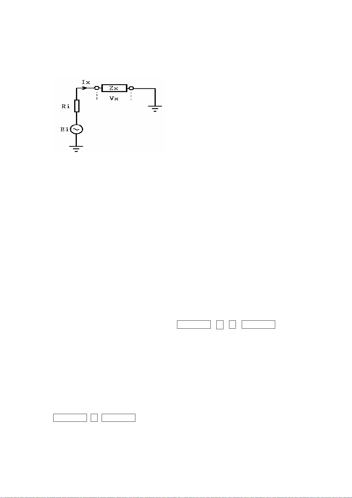
(default) and 100Ω.
In Figure 2-11, Ei: signal source voltage
Ei; Ri: signal source resistance; Zx: the
DUT, Vx is its voltage and Ix current.
Then, Vx=Ei Zx/(Ri+Zx)
Ix= Vx/ Zx= Ei/(Ri+Zx)
When Zx<<Ri,Ix= Ei/ Ri
The level across the DUT and floating
Figure 2-11 Equivalent diagram of signal source output current, are related to the instrument’s
level (refer to §2.2.3 Test signal level), signal source resistance, and the DUT’s
impedance.
When measuring some components that are sensitive to signal’s value, such as
magnetic-core inductor, ceramic capacitor. To compare consistency between
each other, signal should be approximate, when the instrument’s signal source
resistance should be well known.
2.3.7 Key lock
The default state is “OFF”, indicating the keys can be operated, and initialization
state is default.
To avoid operator’s improper operation, the instrument provides the function of
key lock. In this state, all the keys are invalid except unlock key ‘FUNCTIN”. And
the instrument can’t be enabled until the function of key lock is cancelled.
2.3.7.1 Entering key lock
1. The instrument is in the state of normal measurement.
2. Press the following keys in order: FUNCTION, < , ∧, FUNCTION. When
“7-Loc ON” is displayed, exit to the state of “MEASURE”. And the instrument has
been in the state of key lock.
When the instrument is in the state of key lock, all the keys are not available.
And if the instrument is turned off in the state of key lock, it will keep the state
when it’s turned on next time, and measurement state and setting parameters
as well.
2.3.7.2 Exiting key lock
When the instrument is in the state of key lock, press the following keys in order:
FUNCTION, ∧, FUNCTION. And when “7-Loc OFF” is displayed, exit to the state
of “MEASUREMENT”. The instrument returns to normal state.
32
Page 33
2.3.7.3 Notices in the state of key lock
When the instrument is in the state of key lock, all the keys are not available. Do
not think that the instrument is defective. Please operate as §2.3.7.2 says, to
return to the normal state.
2.3.8 Safeguard
TH2810B has RAM inside, which stores some parameters so that they would
lose easily. And the parameters can be stored in RAM are as follows:
1. Measurement frequency, short & open correction parameters at the time of
measuring level;
2. Nominal value and limits;
3. State values at the time of key lock.
2.4 Parameter setup
1. Press LIMIT once in the state of “MEASUREMENT” to enter “parameter
setup”.
2. Parameter symbol is displayed in Display B, and the set value of last time is
display in Display A and unit, with one digit flickering, which is modification digit
(∧, ∨ are operated to move point if the value is decimal, and could be used to
select the unit if unit indicator is flickering.)
3. Operate < and > to flickering digit, and change the value through ∧ and
∨ keys.
4. Press LIMIT to modify the next parameter, or press START to store the value
and exit to the state of “MEASUREMENT”.
5. Repeat the above operations until completing setting all the parameters.
Note: High and low limits are set in the mode of percentage deviation. (Refer to
§2.2.4.2 %△ ). And the limit’s first number means sign (“0” for positive, and “1”
for negative). For example, capacitance with nominal value of 100pF is sorted,
and the range is 97pF – 105pF, then the range in %△ is -3% - 5%.
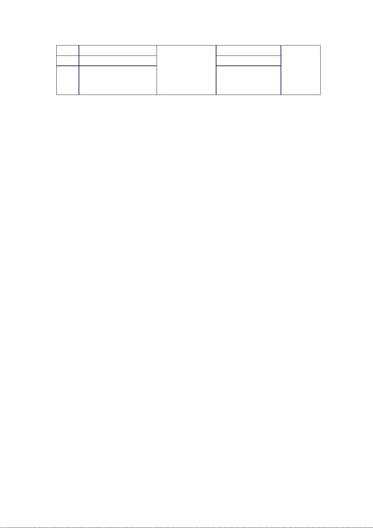
No. Name Display A Display B Note
-
),
)
-
Positive
always
only
1 nominal value 5-digit number
+ 1-digit
decimal point +
1-digit unit
2 high limit of
dissipation or low
limit of quality factor
3 high limit of pin 1 P1
4 low limit of pin 1 P1
5 high limit of pin 2
5-digit number
+ 1-digit
decimal point
first-digit sign +
4-digit number
+ 1-digit
33
Inductance (LS),
capacitance (CS),
resistance (rS),
impedance (ZS)
Dissipation (d
quality factor (q
P2
-
-
-
Page 34
6 Low limit of pin 2 P2-
7 high limit of pin 3 P3-
8 low limit of pin 3
decimal point
(all the
numbers are
input in the
P3-
mode of %△ )
Table 2-7 Limit parameters
necessar
y at 3-pin
sorting
34
Page 35
Chapter 3 Component measurement
This chapter provides description of instrument operation and lists some
measurement examples.
3.1 Unpacking and inspection
3.1.1 Notices
1. After unpacking, please verify with packing list.
2. Read Operation Manual in details before operating the instrument, especially
some notes and notices; or operate the instrument under instruction of
professional personnel.
3. Power
The instrument adopts the power supply of 220VAC±10%/50Hz±5%.
Before switching on the power supply, make sure that line voltage is correct.
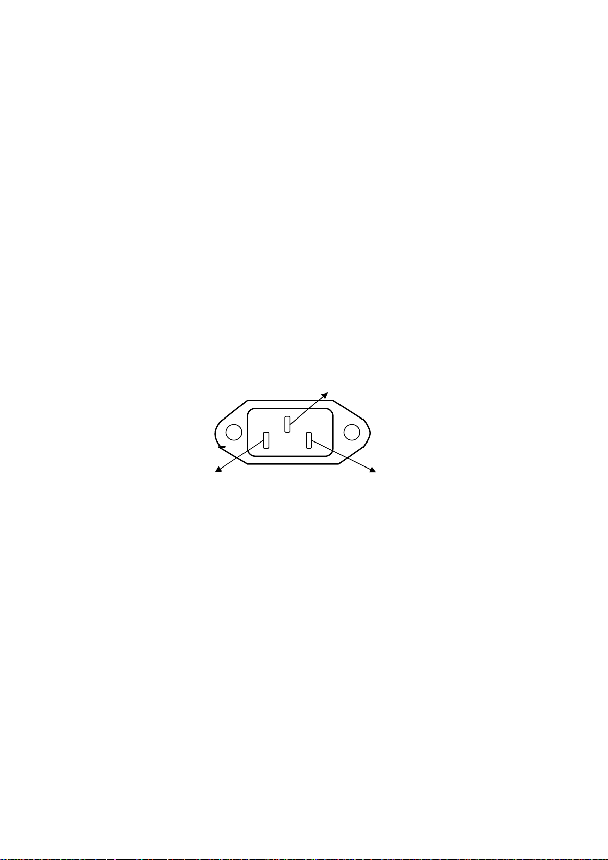
Neutral, Line and Earth should be connected correctly as shown in Figure
3-1:
Earth
Neutral Line
Figure 3-1 Power Supply Receptacle
For protection from electrical shock, the power cable ground must not be
defeated. The power plug must be plugged into an outlet that provides a
protective earth ground connection.
Then outlet can’t be shared with those devices consuming large power to
avoid interference or damage of the instrument.
4. The instrument should be operated under the environment conditions
specified in the manual. Always keep the instrument and the test terminals
away from electrical and magnetic field to avoid influence of the
measurement accuracy.
5. Allow the instrument to warm up a minimum of 10 minutes before starting
any of the performance tests.
6. Turn off the power supply and draw out the plug, when instrument is not in
use, or when covers need to be removed for troubleshooting.
3.1.2 Common component measurement
1. Switch on the power supply correctly. And the instrument’s default
35
Page 36
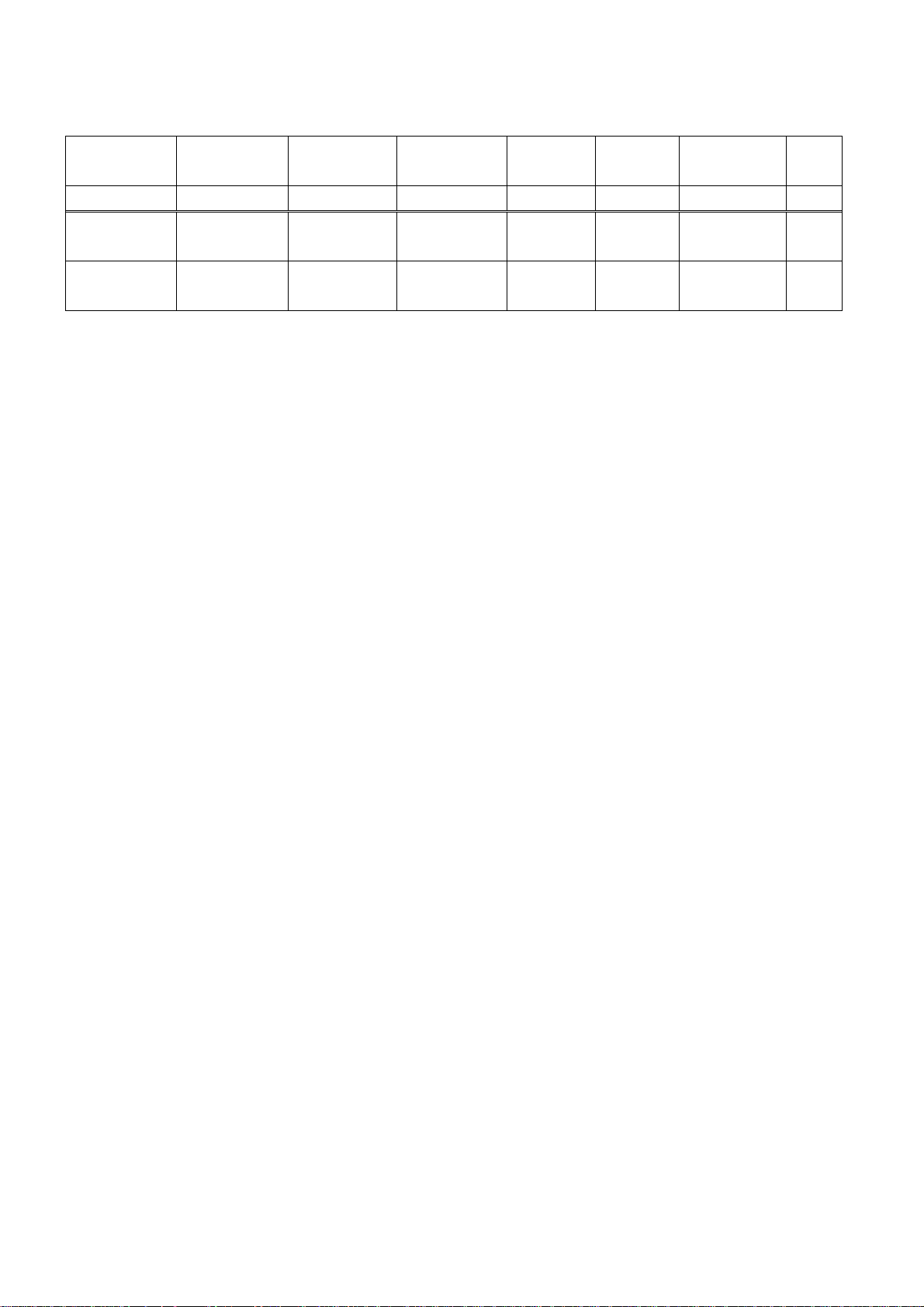
measurement status is shown in table 3-1.
outer
function
parameter C-D
parameter frequency level display range speed clear
note
1kHz 1.0V direct auto slow open
inner
function
parameter off off serial
alarm trigger equivalent serial
connection
Table 3-1 Default status
Note: TH2775B’s default parameter is L-Q.
2. Select measurement parameter: L/Q, C/D, R/Q, Z/Q or R/D (only for
TH2618B).
3. If necessary, select equivalent mode, referring to §2.3.3 on P2-19.
4. Select measurement frequency and test signal level.
5. If
6. Connect test fixtures
necessary, select suitable signal source resistance, referring to §2.3.6 on
P2-19.
NOTE 2
or cables. Test fixture TH26001 and 4-terminal Kelvin
test cable TH26004 are equipped along with the equipment. Test fixture
Th26005 is optional for meter with little space between components, and
TH26009 is for SMD component.
7. Perform a short correction, using a shorting bar to test fixture or cable.
8. Perform an open correction without the shorting bar.
9. Connect the component to the te
st terminals and the measurement values
are displayed in Display A and B.
interface
receiving
only
sorting
mode
3-pin
sorting
NOTE 3
source
resistance
30Ω off
NOTE 1
Key
lock
Note 1: When the DUT’s Q or D is large enough, even close to 1, the
measurement values in serial and parallel connections differ a lot.
For example, a capacitance in serial model is Cs = 0.1μF, and dissipations
respectively are D1 = 0.0100, D2 = 0.1000 and D3 = 1.0000, then according to
2
fourmula Cp=Cs/(1+D
), capacitances in parallel model are:
Cp1 = 0.09999μF
Cp2 = 0.09901μF
Cp3 = 0.05μF
You can find that, when D<0.01, the difference between Cs and Cp is very small,
but while D>0.01, the difference will be very obvious. For example, when D =
0.1, the difference between Cs and Cp in percentage is approx. 1%, while D =
1, the difference in percentage will be approx. 100%.
Note 2: At the time of measuring component which is sensitive to signal, such as
core inductor, ceramic capacitor, it should be compared with the same signal to
keep the consistency. In this case, not only test signal level should be selected,
but also signal source resistance.
For example, a ceramic capacitor is measured by HP4284A to be of the
parameter of 0.1µF, but it’s measured to be 0.11µF by TH2810B at the same
36
Page 37

level. The reason is that HP4284A’s signal source resistance is 100Ω, while
TH2810B’s is 30Ω. According to §2.3.6 on P2-19, we know that voltage on the
DUT is different even their level is the same. So change TH2810B’s resistance to
100Ω, and the same measurement value will be got.
Note 3: Refer to §2.2.7 on P2-8 to perform correction. Improper correction will
lead to instrument’s inaccurate result, even out of work. And the common
improper operations are: a) At the time of short or open correction, the DUT is
connected; b) Connect HD, HS and LD, LS together to perform short correction.
3.2 Connection of Component
3.2.1 Measurement of Capacitor
Do not apply DC voltage or current to the test terminals. Doing so will damage
the instrument. Before you measure a capacitor, be sure the capacitor is fully
discharged.
3.2.2 Connecting the Component
TH2810B has four test terminals and the outer shields of each terminal are
connected with the instrument ground, the outer shield can be looked as the
fifth terminal. Descriptions of the five terminals are as follows:
HD: high drive terminal of current;
LD: low drive terminal of current;
HS: high sense terminal of voltage;
LS: low sense terminal of voltage;
┴: Ground.
The ground shields are used reduce influence of stray capacitance and
electromagnetic disturbance. HD, HS and LD, LS should be connected at the
lead of the component under test in order to reduce the influence of cable
resistance and contact resistance especially in D measurement. At the time of
measuring low impedance,
connected to leads of component separately so as to avoid the influence of lead
resistance.
In other words, HD, HS and LD, LS cannot be connected before connecting to
the component otherwise measurement error will be caused.
If contact resistance and leads resistance R
tested (for example R
HD, HS and LD, LS can be connected together before connecting to the
component under test (two-terminal measurement).
Test fixture is recommended when high accuracy is required. Kelvin test cables
have better performance when measurement frequency is less than 10 kHz but
it can hardly meet the accuracy requirement when frequency is larger than 10
kHz, because different positions of test leads will directly influence the stray
the drive terminals and sense terminals should be
are far less than the impedance
lead
< Zx/1000, and the accuracy required is 0.1%), then
lead
37
Page 38

capacitance and inductance between the test terminals.
Therefore, test fixture is recommended for high frequency measurement. If the
test cable must be used, try you best not to move the cable during the
corrections and measurements.
38
Page 39

Chapter 4 Packing and Warranty
4.1 Packing
The contents are listed as follows:
Description Quantity
1) TH2810B/TH2618B/TH2775B 1
2) TH26011 Kelvin Test Fixture
3) TH26004-1 5-terminal Test Cable
3) TH26010 Shorting Bar 1
4) Three-Wire Power Cable 1
5) Fuse (1A) 2
6) Operation Manual 1
7) Quality Certificate 1
8) Test Report 1
9) Warranty Card 1
And the following are optional:
TH2810B-HANDLER Interface Cable TH2810B-RS232C Interface Cable
TH12011/2/3- RS232C Interface Software TH26004 5-terminal Test Cable
TH26005&TH26006 Axial Test Fixture TH26007 Core Test Fixture
TH26008 SMD Test Fixture TH26009 SMD Kelvin Test Tweezers
Check the contents when you received the instrument. If the contents are
incomplete, if there is mechanical damage or defect, or if the instrument does
not pass the power-on self-tests, please contact our company or business
department immediately.
1
1
4.2 Warranty
The period of warranty: the period of warranty will start from the date the
instrument is delivered. The period of warranty is two years. The warranty card
is needed when the instrument needs to be repaired. The foregoing warranty
shall not apply to defects resulting from improper or inadequate maintenance
by Buyer.
39
 Loading...