

Page 1

TH2512
DC Milliohmmeter
Instruction Manual
Page 2

arranty ..................................................................................................................................................... 3
W
Safety Precautions.................................................................................................................................... 4
Chapter 1. Introduction ........................................................................................................................5
1.1 Unpacking and Inspection .......................................................................................................5
1.2 Product Overview.................................................................................................................... 5
1.3 Controls and Indicators............................................................................................................ 6
1.3.1 Front Panel Controls and Indicators....................................................................... 6
1.3.2 Rear Panel Controls and Connectors .................................................................... 7
1.4 Installation ............................................................................................................................... 7
1.4.1 Dimensions ................................................................................................................7
1.4.2 Power Requirements ................................................................................................ 7
1.4.3 Safety Inspection....................................................................................................... 8
1.5 Specifications........................................................................................................................... 8
1.5.1 Resistance Range:.................................................................................................... 8
1.5.2 Measurement Rate ...................................................................................................8
1.5.3 Trigger......................................................................................................................... 8
1.5.4 Ranging ......................................................................................................................8
1.5.5 Zeroing........................................................................................................................ 9
1.5.6 Comparator ................................................................................................................ 9
1.5.7 Display ........................................................................................................................ 9
1.5.8 Beep Alarm ................................................................................................................9
1.5.9 Interfaces.................................................................................................................... 9
1.5.10 Unknown Connector ................................................................................................. 9
1.5.11 Dimensions ................................................................................................................9
1.5.12 Weight......................................................................................................................... 9
1.5.13 Environmental.......................................................................................................... 10
1.5.14 Power........................................................................................................................ 10
Chapter 2. Operatio
n.......................................................................................................................... 11
2.1 Startup.................................................................................................................................... 11
2.2 Display................................................................................................................................... 11
2.3 SPEED................................................................................................................................... 11
2.4 Measurement mode................................................................................................................ 11
2.5 Comparator Function............................................................................................................. 12
2.6 ZERO..................................................................................................................................... 13
2.7 RANGE ................................................................................................................................. 13
2.8 Beeper.................................................................................................................................... 14
Chapter 3. Handler Interface............................................................................................................. 15
3.1 Handler Interface................................................................................................................... 15
2
Page 3

Warranty
This Tonghui instrument product is warranted against defects in material and workmanship for
a period of one year from the date of shipment. During the warranty period, Tonghui company
will, at its option, either repair or replace products which prove to be defective. For warranty
service or repair, this product must be returned to a service facility designated by Tonghui.
The foregoing warranty shall not apply to defects resulting from improper or inadequate
maintenance by Buyer, Buyer-supplied software or interfacing, unauthorized modifications for
the product, or improper site preparation or maintenance.
No other warranty is expressed or implied. Tonghui specifically disclaims the implied
warranties of merchantability and fitness for a particular purpose.
Tonghui shall not be liable for any direct, indirect, special or consequential damages, whether
based on contact, tort, or any other legal theory.
3
Page 4

Safety Precautions
CAUTION
The TH2512 DC Milliohmmeter is a low voltage instrument and provides no more
than 1A DC output to the device under test (DUT). Some devices tested
(especially capacitors) can store charge and may cause a hazard if not
discharged properly. Follow these safety instructions.
1. Operate the TH2512 unit with its chassis connected to earth ground. The instrument is
shipped with a three-prong power cord to provide this connection to ground. This power
cord should only be plugged in to a receptacle that provides earth ground.
2. Plug the Kelvin low ohm clip leads into the unknown terminal.
3. Before touching the test lead wires or output terminals make sure any capacitive device
has been fully discharged.
4. In the case of an emergency, turn OFF the POWER switch using a “hot stick” and
disconnect the AC power cord from the wall. Do not touch the TH2512 instrument.
4
Page 5
Chapter 1. Introduction
1.1 Unpacking and Inspection
Inspect the shipping carton before opening. If damaged, contact the carrier agent
immediately. Inspect the TH2512 DC Milliohmmeter instrument for any damage. If the
instrument appears damaged or fails to meet specifications notify Tonghui (refer to
instruction manual front cover) or its local representative. Retain the original shipping carton
and packing material for future use such as returning the instrument for recalibration or
service.
1.2 Product Overview
The TH2512 DC Milliohmmeter is a precision low resistance meter for production or
laboratory testing of individual components, materials, printed circuit boards and other
resistive items. The TH2512 instrument provides nine measurement ranges from 20m to
2M over seven current ranges from 1μA to 1A. The basic measurement accuracy is
0.05%. Measurement rate is selectable (Slow or Fast) with rates up to 10 measurements
per second. Automatic or Hold Range can also be selected. Measurements can be made
continuously or triggered. The Handler interface is standard and the IEEE-488/RS232
interface is optional equipment on the TH2512 instrument. The effects of series resistance
in the test leads can be zeroed with the short correction function. The TH2512 instrument is
equipped with Pass/Fail bins. High and low limits set in the Comparator function display the
measured result as a percent. Compare results can be indicated on the front panel as well.
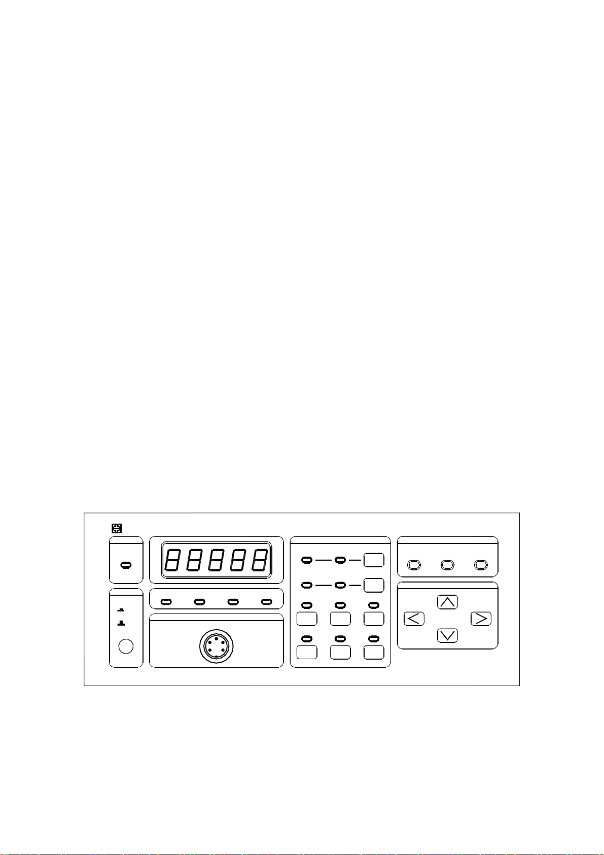
Four-terminal Kelvin connection to the device under test is obtained through the unknown
terminal on the front panel.
TH2512 illiohmmeter DC M
REMOTE
ON
POWER
ON
OFF
FUNCTION
R
mΩ
Ω
UNKNOWN
MΩkΩ
ON ON
CONT
ON ON
TRIG
%
SLOWFAST
SORT
ZERO
DISP
SPEED
ON
SETUP
AUTO
RANGE
COMPARATOR INDICATION
LOW
TONGHUI ELECTRONIC
PASS
CURSOR
HIGH
Figure 1-1: TH2512 DC Milliohmmeter
5
Page 6
1.3 Controls and Indicators
1.3.1 Front Panel Controls and Indicators
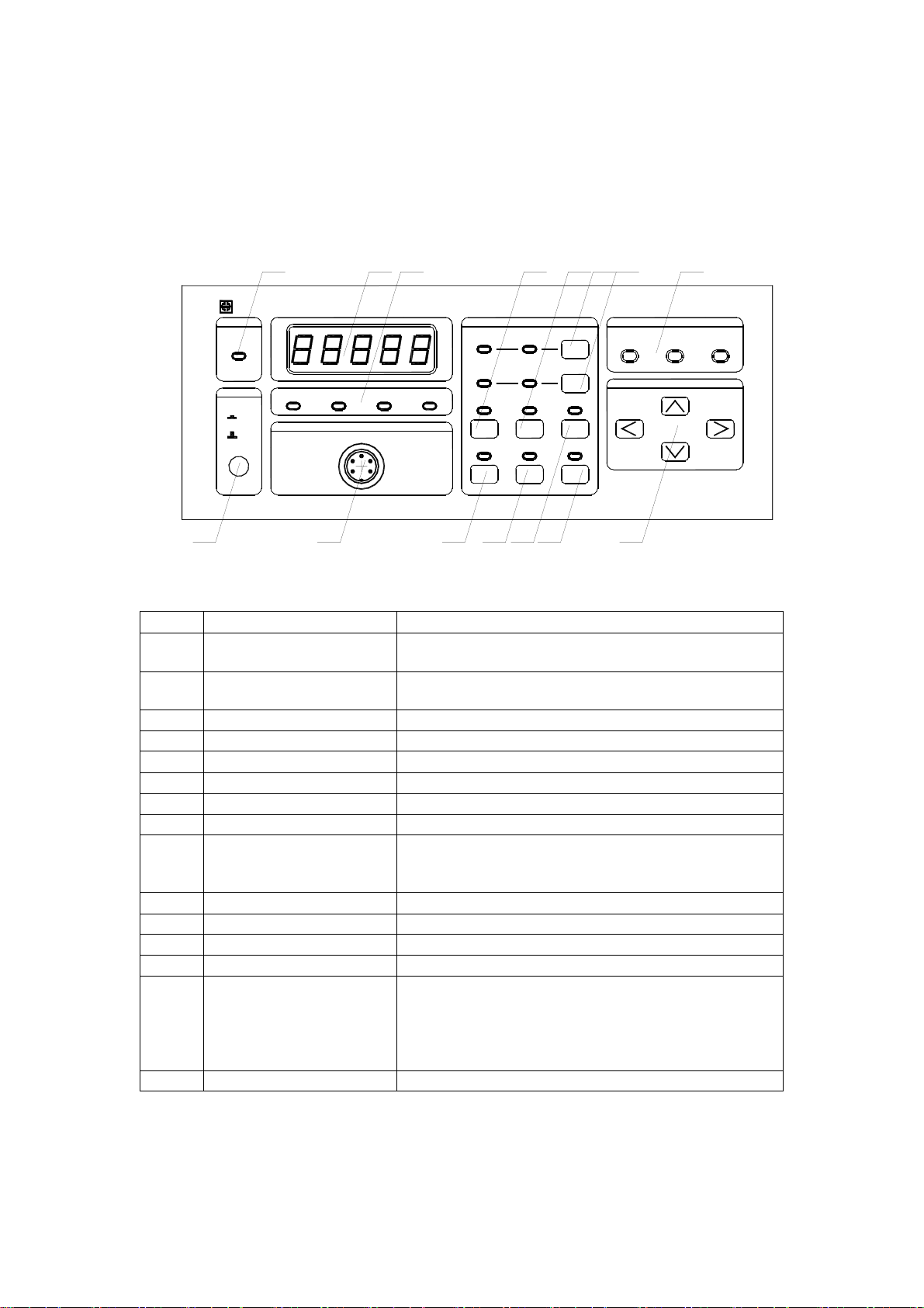
Figure 1-2 illustrates the controls and indicators on the front panel of the TH2512 DC
Milliohmmeter instrument. Table 1-1 identifies them with description and function.
123
DC M
TH2512 illiohmmeter
REMOTE
ON
POWER
mΩ
ON
OFF
Ω
UNKNOWN
kΩ
MΩ
R
ON ON
CONT
ON ON
4657 8
FUNCTION
%
SLOWFAST
SORT
DISP
SPEED
ON
SETUP
AUTO
COMPARATOR INDICATION
LOW
PASS
CURSOR
HIGH
15 14 13
Figure 1-2: TH2512 Front Panel Controls & Indicators
Table 1-1: TH2512 Front Panel Controls & Indicators
NO.
1
2
3
4
5
6
7
8
Remote Indicator
Measurement display
Unit indicators
CONT key
SORT key
DISP key
SPEED key
Comparator indication
Name
9 CURSOR keys
10
11
12
13
RANGE key
SETUP key
ZERO key
TRIG key
14 UNKNOWN terminal
15
POWER button
ZERO
RANGE
TONGHUI ELECTRONIC
TRIG
1112 10 9
Function
When TH2512 is controlled by IEEE488/RS232
interface, this led is ON.
Display the measurement result.
Display the limit setup information.
Display the current unit.
Set the instrument continuous test mode.
Turn on/off the comparator function.
Select the direct or percent display mode.
Set the measurement rate: FAST/SLOW.
Indicate the comparator results.
Select a digit to modify.
Increase/decrease by 1.
Range selection.
Set range mode: AUTO/HOLD.
Comparator parameters setup.
Eliminate the lead resistor effect.
Set the trig mode and trigger the measurement.
Current Drive Terminal, Low (-)
Voltage Sense Terminal, Low (-)
Voltage Sense Terminal, High (+)
Current Drive Terminal, High (+)
Shielding Terminal.
POWER ON/OFF switch.
6
Page 7
1.3.2 Rear Panel Controls and Connectors
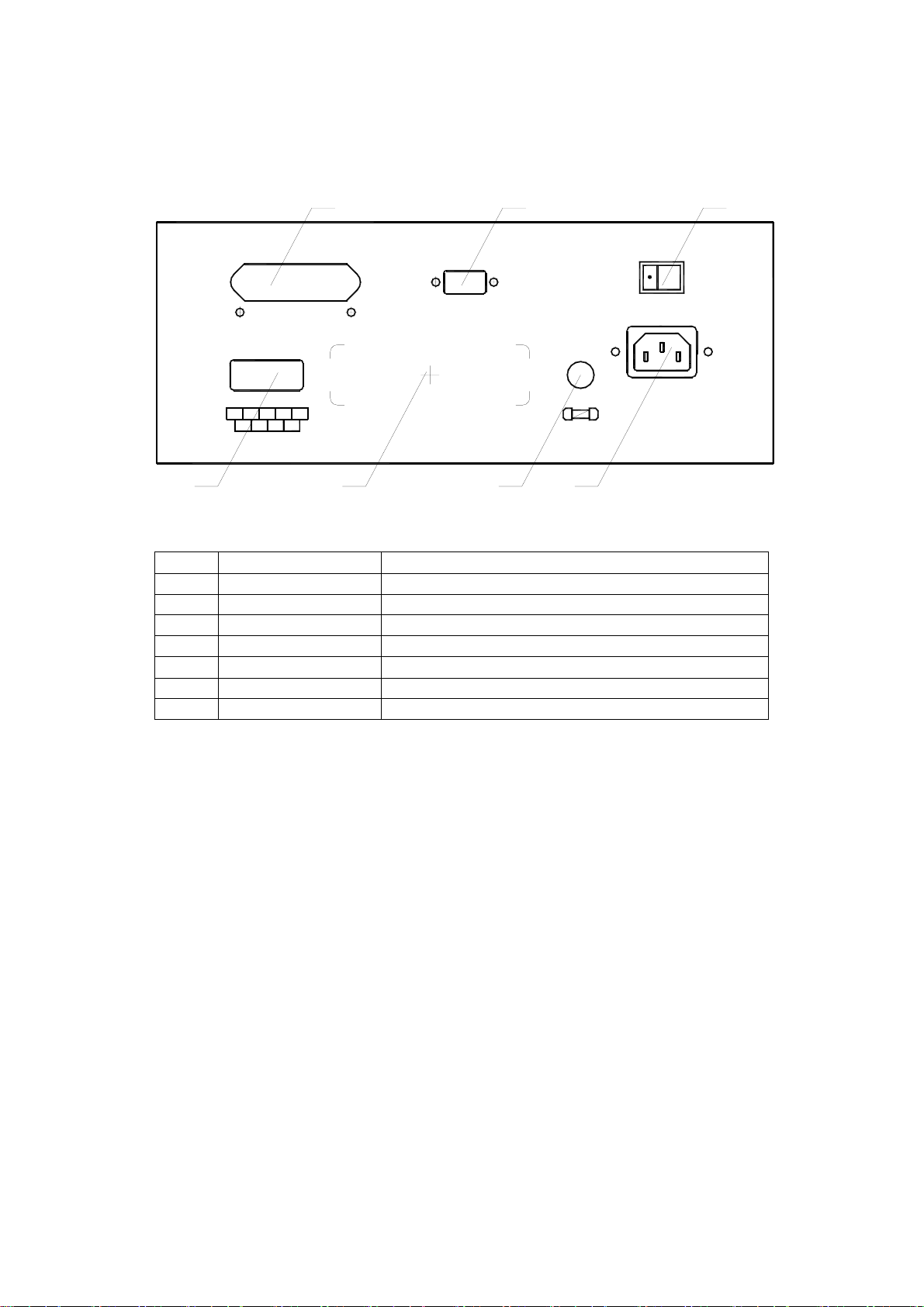
Figure 1-3 illustrates the controls and connectors on the rear panel of the TH2512 DC
Milliohmmeter instrument. Table 1-2 identifies them with description and function.
321
RS-232
FUSE
250V/F1A
HANDLER
5
TRIG
GND
9
EOT
PASS
NC
IEEE-488
1
HI
LO
NC
+5V
6
76 54
BUZZER
ON OFF
INPUT
50Hz 220V
15VA MAX
Figure 1-3: Rear Panel TH2512 Instrument
Table 1-2: TH2512 Rear Panel Controls & Connectors
NO.
Name
Function
1 IEEE488 Interface IEEE-488 Interface connector for data transfer
2 RS232 Interface RS 232 interface for remote operation
3 Buzzer switch Turn ON/OFF the buzzer
4 AC line input Connection to AC power source
5 FUSE Short circuit protection
6 Nameplate Nameplate for production information.
7 Handler interface Handler Interface connector for remote operation
1.4 Installation
1.4.1 Dimensions
W×H×D: 270 mm×110 mm×330 mm
1.4.2 Power Requirements
The TH2512 can be operated from a power source of 190 to 250V AC. Power connection is
via the rear panel through a standard receptacle. Always use an outlet that has a properly
connected protection ground.
7
Page 8

1.4.3 Safety Inspection
Before operating the instrument inspect the fuse holder on the rear of the TH2512
instrument to ensure that the properly rated fuse is in place, otherwise damage to the unit is
possible.
Make sure the instrument is only used with the approved international cord set to ensure
that the instrument is provided with connection to protective earth ground.
The surrounding environment should be free from excessive dust to prevent contamination
of electronic circuits. The surrounding environment should also be free from excessive
vibration. Do not expose the TH2512 instrument to direct sunlight, extreme temperature or
humidity variations, or corrosive chemicals.
1.5 Specifications
1.5.1 Resistance Range:
Range F.S Resolution Accuracy Test I (typical) Test Voltage
20 m
200 m
2
20 1 m
200 10 m
2 k 100 m
20 k 1
200 k 10
2 M 100
1μ ±(0.1% of rdg+ 3ct)
10μ ±(0.05% of rdg + 2ct)
100μ ±(0.05% of rdg + 2ct)
±(0.05% of rdg + 2ct)
±(0.05% of rdg + 2ct)
±(0.05 % of rdg + 2ct) 100μA
±(0.05% of rdg + 2ct) 10μA
±(0.05% of rdg + 2ct) 10μA
±(0.05% of rdg + 2ct) 1μA
1A
100mA
100mA
10mA
1mA
<1.0V DC
<4.0V DC
1.5.2 Measurement Rate
Fast: 10 measurements/second
Slow: 2.5 measurements/second
1.5.3 Trigger
Manual, Internal or External
1.5.4 Ranging
Automatic or Hold Range
8
Page 9

1.5.5 Zeroing
Short circuit compensation
1.5.6 Comparator
LOW, PASS and FAIL indication.
Comparator parameters setup: Nominal, Hi and Lo Limits
1.5.7 Display
4 1/2 digits LED display.
1.5.8 Beep Alarm
Beep alarm for PASS can be turned on/off by the switch from the rear panel.
1.5.9 Interfaces
Standard Interfaces: Handler
Optional Interfaces: RS232 and IEEE-488
1.5.10 Unknown Connector
Current Drive Low Terminal: DVoltage Sense Low Terminal: SVoltage Sense High Terminal: D+
Current Drive High Terminal: S+
Shielding Terminal.
1.5.11 Dimensions
W x H x D: 270 mm x 110 mm x 330 mm
1.5.12 Weight
About 3.5 kg net
9
Page 10

1.5.13 Environmental
Specifications: 10℃ to 30℃, <75% RH
Operating: 0℃ to 40℃, <75% RH
Storage: -25℃ to 55℃, <90% RH
1.5.14 Power
198-242VAC
50Hz/60Hz
Consumption <30VA
10
Page 11

Chapter 2. Operation
2.1 Startup
Connect the instrument power cord to the source of proper voltage.
The instrument is to be used only with three-wire grounded outlets.
Power is applied to the TH2512 instrument by pressing the red power switch on the front
panel to the ON position. The TH2512 unit should warm up for a period of at least 15
minutes prior to measurements being made.
2.2 Display
TH2512 provides two display mode: “R” and “%”.
R: The direct measurement value of the device under test.
%: The difference of the measured value and a previously stored reference value is
displayed as a percentage of the reference value.
Perform the following steps to set the display mode.
1. The default display mode is “R”, when TH2512 is turned on.
2. “%” mode can only be used when comparator function is turned on.
3. Press SORT key to turn on the comparator function and the corresponding led turns on.
4. Press DISP key to select the display mode “R” or “%”.
5. If you press SORT key to turn off the comparator function. The display mode will return
to “R” mode, despite of the original display mode you select.
2.3 SPEED
The TH2512 instrument can be programmed for Slow (2.5measurements/second), or Fast
(10 measurements/second) test times. The basic accuracy (0.05%) is specified for the slow
measurement speed. The instrument default setting is SLOW.
Perform the following steps to set the measurement speed.
1. Press SPEED key to select the measurement speed: FAST or SLOW.
2. The FAST or SLOW led flashes one time after a measurement is finished.
2.4 Measurement mode
The TH2512 provides two measurement mode: “CONT” and “TRIG”. The instrument default
setting is CONT mode.
CONT: TH2512 measures the device and displays the result continuously.
TRIG: TH2512 measures the device and displays the result once after TH2512 is
Page 12

triggered from the front panel or through the Handler interface.
Perform the following steps to set the measurement mode.
1. The instrument default setting is “CONT” mode, the CONT led is ON.
2. Press TRIG key to set the “TRIG” mode, the TRIG led is ON and the CONT led is OFF.
3. Press TRIG key to start a measurement, when TRIG led is ON.
4. You can also start a measurement through the Handler interface, when TRIG led is ON.
5. Press CONT key to set the “CONT” mode, the CONT led is ON and the TRIG led is
OFF.
2.5 Comparator Function
With its built-in comparator, the TH2512 can output comparison results for sorting
components into PASS, HIGH, and LOW bins. By using the handler interface, the TH2512
can easily be combined with a component handler, and a system controller to fully automate
component testing, sorting, and quality control data processing.
Perform the following steps to set the comparator on/off.
1. The instrument default setting is comparator OFF and SORT led is off.
2. Press SORT key to turn on the comparator function, and SORT led is on; Ranging
mode is automatically changed to HOLD, and current measurement range is held.
3. When comparator is ON, you can change the display mode: “R” or”%”. The comparison
results are indicated by the LEDS on the front panel and sent out through the Handler
interface at the same time.
4. Press SORT key again to turn off the comparator function. The ranging mode is
automatically changed to AUTO. The display mode will be set to “R” mode, if the
previous display mode is “%”.
Perform the following steps to set the comparator parameters.
1. Press SETUP key, “-Std-” will be displayed for 1 second, and then the previously stored
standard value will be displayed. The SETUP led flashes.
2. The first digit flashes. Use the ← key and → key to select which digit to be modified.
3. Use the ↑ key and ↓ key to increase or decrease the flashing bit.
4. Press SETUP key again, “-Lo-” will be displayed for 1 second, and then the previously
stored low limit value will be displayed.
5. The first digit flashes. Use the ← key and → key to select which digit to be modified.
6. Use the ↑ key and ↓ key to increase or decrease the flashing bit.
7. Press SETUP key again, “-Hi-” will be displayed for 1 second, and then the previously
stored high limit value will be displayed.
8. The first digit flashes. Use the ← key and → key to select which digit to be modified.
9. Use the ↑ key and ↓ key to increase or decrease the flashing bit.
10. Press SETUP key again, the TH2512 will return back to the measurement state and the
SETUP led turns off.
12
Page 13
2.6 ZERO
Short circuit compensation can be performed on the test leads/fixture by selecting the
ZERO function = ON.
Perform the following steps to ZERO the short circuit offset.
1. The instrument default setting is ZERO off.
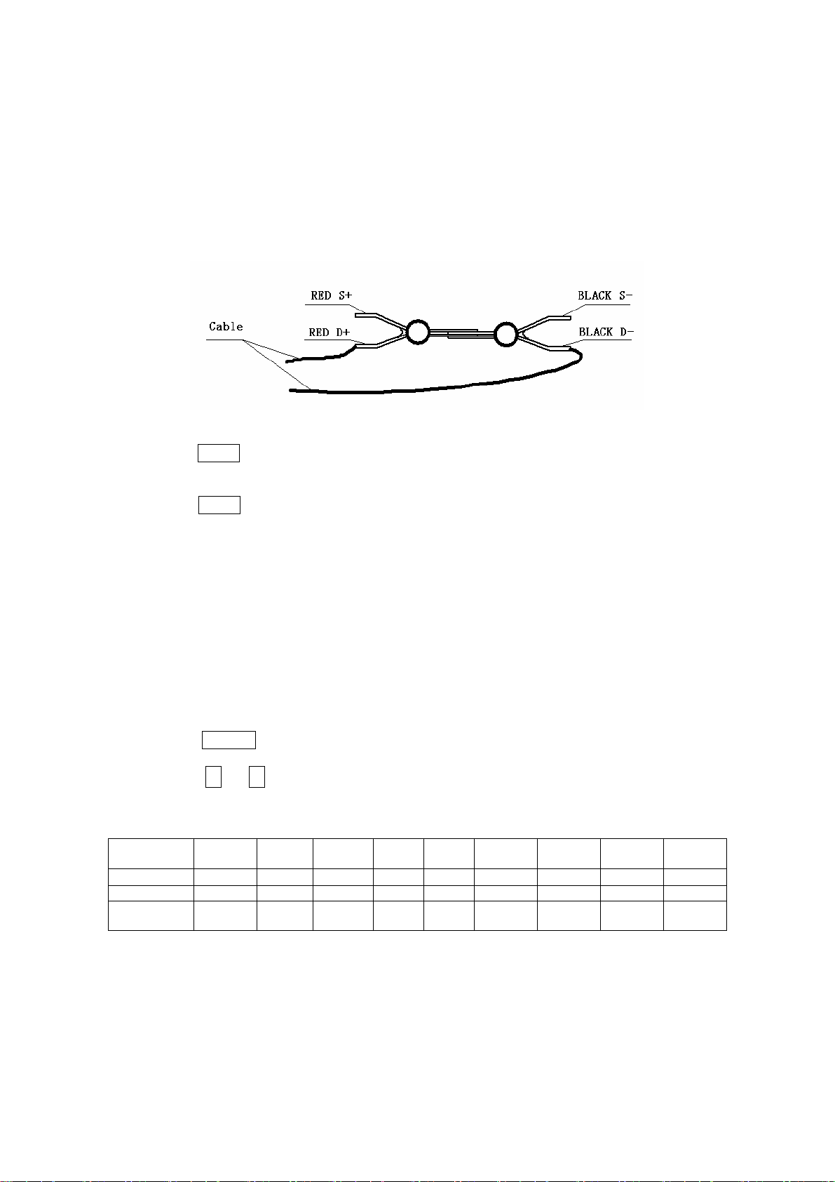
2. Short the test clips as shown in Figure 2-1, make sure that “S+” and ”S-” are connected
directly and “D+” and “D-” are also connected directly.
Figure 2-1 Short the test clips
3. The instrument displays the current short circuit resistance.
4. Press ZERO key to turn on the ZERO function, ZERO led turns on.
5. When ZERO function is ON, the short circuit resistance will be eliminated from the
measurement value every measurement.
6. Press ZERO key again to turn off the ZERO function, ZERO led turns off and the short
circuit resistance will not be eliminated from the measurement value every
measurement.
2.7 RANGE
The TH2512 instrument’s measurement range can be set as AUTO or HOLD.
TH2512’s measurement ranges are 20m, 200m, 2, 20, 200, 2k, 20k, 200k
and 2M.The instrument default setting is AUTO Range.
Perform the following steps to set the range mode.
1. The instrument default setting is AUTO Range, the AUTO led is ON.
2. Press RANGE key to set the range HOLD mode. The AUTO led is off and the current
range is held.
3. Press ← or → key to select a measurement range manually. The display point and
unit will be changed with the range selected as shown in Table 2-1.
Table: 2-1: Measurement Range, Point and Unit
Full-Scale
Range
Resolution
Unit
Point
Position
20m
1μ 10μ 100μ 1m 10m 100m 1 10 100
m m k k k M
xx.xxx xxx.xx x.xxxx xx.xxx xxx.xx x.xxxx xx.xxx xxx.xx x.xxxx
200m
2 20 200 2k 20k 200 k 2M
13
Page 14

2.8 Beeper
The beeper alarms when the device under test is sorted into PASS Bin. The beeper can be
turned off from the rear panel.
14
Page 15
Chapter 3. Handler Interface
P
H
3.1 Handler Interface
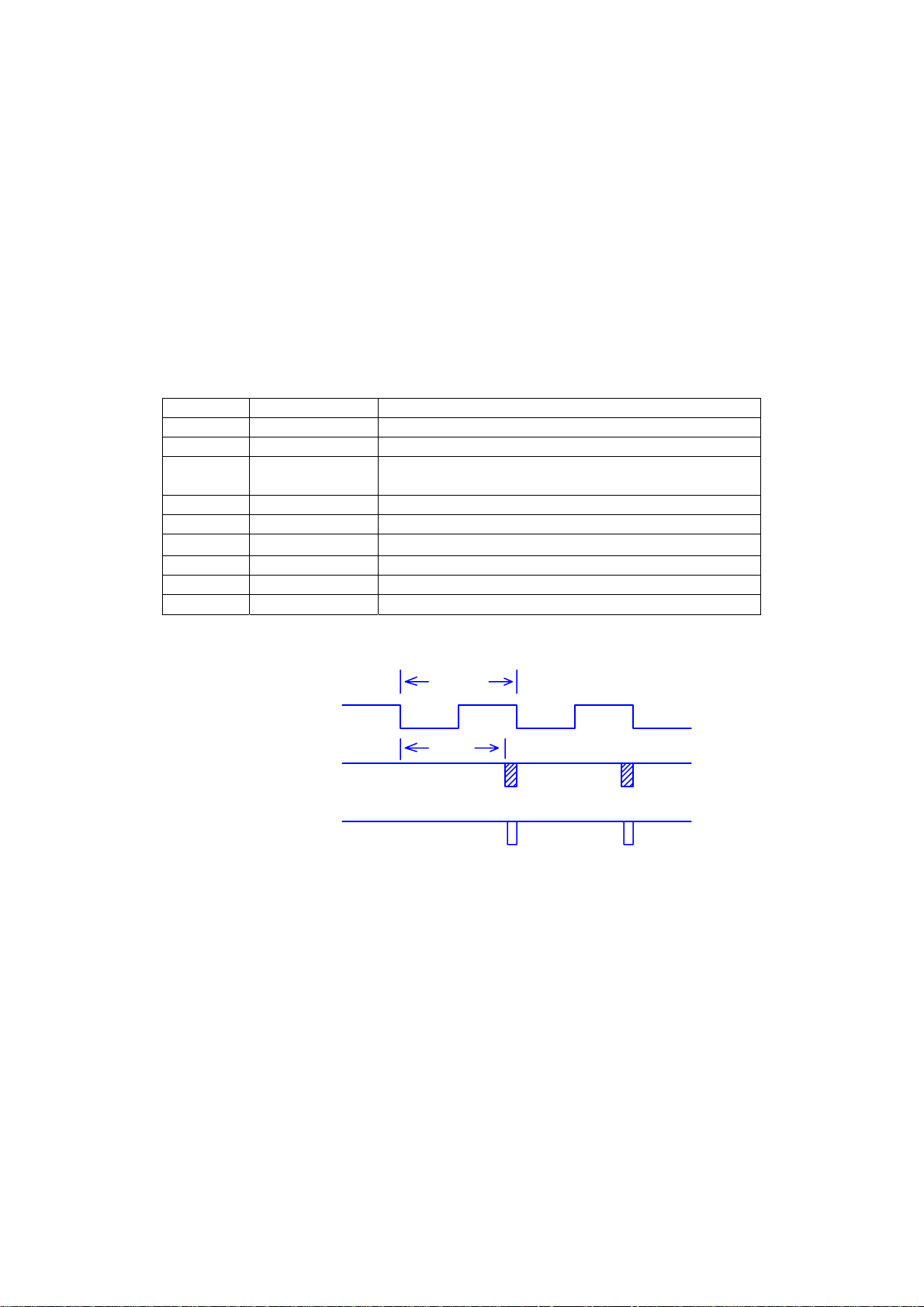
Turn on comparator function, the comparison results will be sent out through the Handler
interface. And the TH2512 can be triggered through the handler interface. The pin
assignments is shown as table 2-2 and the timing diagram is shown as figure 2-2.
Table 2-2 Handler Interface Pin Assignments
Pin No. Signal Name Description
1 /LOW Measurement value is less than the low limit
2 /HIGH Measurement value is more than the high limit
3 /PASS Measurement value is between the high and low
limits
4 /EOT End of test signal
5 /EXT.TRIG External trigger signal(Low valid)
6
7 N.C. Not connected
8 N.C. Not connected
9 GND Ground terninal
+5V(VCC)
+5V Power source
TRIG
ASS,LOW,HIG
EOT
Figure 2-2 T
≥ 100mS
80mS
iming Diagram (Fast Speed)
15
 Loading...