

Page 1
969 Horsham Road lHorsham, Pennsylvania 19044 USA l Phone: 215-675-2053 Fax: 215-675-7543 linfo@tonercable.com
&01/$/RXGQHVV$QDO\]HU
Features
LLoudness measurement to ITU-R BS.1770
•
True peak measurement to ITU-R BS.1770 with five times oversampling
•
Integrated TC Electronic® loudness radar display
•
Trend chart of levels (15 seconds to 24 hours)
•
Export values to a PC
•
Audio status display of clips, mutes, average, high and low levels
•
Meter up to 16 channels
•
Alarms for levels, status and Dolby® metadata
•
Two triple rate SDI inputs
•
Optional eight AES inputs
•
Optional Four AES and eight analog outputs
•
Adjustable output delay
•
Optional Dolby® AC3 and E decoding (requires AES I/O option)
•
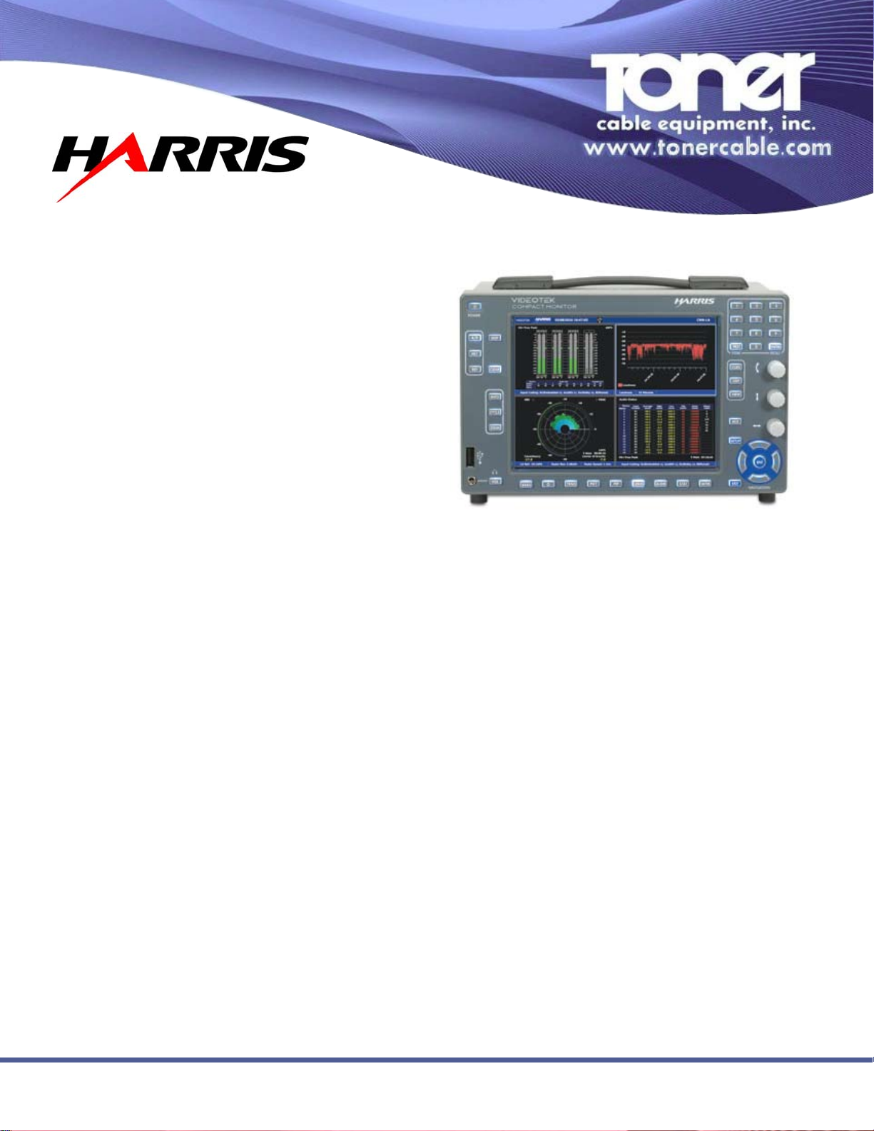
Part of the Videotek® Compact Monitor Series, the CMN-LA loudness analyzer is
a comprehensive audio monitoring tool that makes it easy to confirm compliance
Product details•
The The basic CMN-LA unit operates with 3G/HD/SD-SDI embedded audio sources,
with a hardware option for eight AES inputs, four AES outputs and eight analog outputs.
The analog outputs are meant to drive high impedance loads.
Dolby® decoding is a hardware option available at the time of order, or for field installation. The Dolby® decoder requires the AES I/O option. The AES option also includes
an LTC input for time stamping of log entries.
The CMN-LA also includes internal speakers and a front-panel headphone jack for
source confirmation. A mixdown mode can be applied to the headphone output when
using discreet sources. The mixdown parameters are taken from VANC medatada if
present, otherwise internal menu settings are used.
with the latest loudness requirements. Loudness and true peak measurements
are made to the ITU-R BS.1770 standard with five times oversampling. Built-in
modes offer quick setup to ATSC A/85 or EBU R 128 recommendations. Up to five
days of loudness data are stored internally and easily retrieved through the USB
port or internal web server. Metering of up to 16 channels simultaneously makes
for rapid alignment checks.
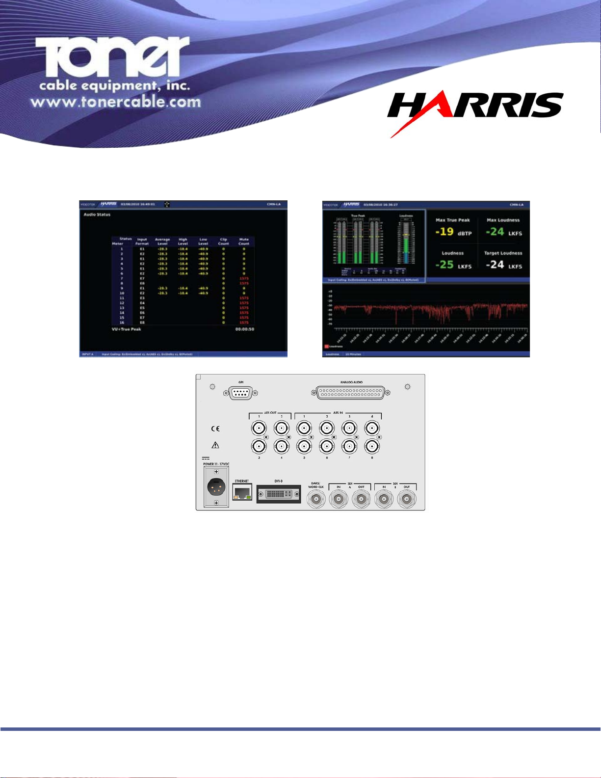
Integated into the CMN-LA is the TC Electronic
shows loudness on short-terms meters, graphs covering periods from one minute to 24 hours, and numeric display of the long-term center of gravity (average
loudness) and consistency (loudness range). The flexible display of the CMN-LA
presents data in a format most useful for the job at hand. Use the integrated TC
Electronic loudness radar meter during production, the audio status display during
program ingest, and the combination of loudness and true peak meters, numeric
display and trend chart for master control monitoring. The chart data can be exported for compliance reporting. Adjustable audio output delay compensates for
video monitor processing in critical evaluation suites.
®
loudness radar meter, which
sPeciFications
Specifications are subject to change without notice.
Digital Audio Input
Audio Formats . . . . . . . . . . . . . . . AES/EBU (optional), embedded audio
AES Input Connector Type . . . . . . . 8 BNC, female
AES Input Impedance . . . . . . . . . . 75 ohms nominal
AES Input Return Loss . . . . . . . . . ≥25 dB, 0.1 to 6 MHz (unbalanced)
AES Input Level . . . . . . . . . . . . . . 0.2 to 2 V
AES Input Sample Rate . . . . . . . . . 32 kHz, 44.1 kHz, 48 kHz, 88.2 kHz, 96 kHz
(audio inputs are sample rate converted to 48 kHz)
Meter Accuracy Over Frequency . . ±0.1 dB from 20 Hz to 19 kHz with 0 to -40 dBFS
sine wave input, except for within 7 Hz of some
submultiples of the 240 kHz oversampling frequency
toring rack or on the meter bridge of an audio console.
Digital Audio Output
AES Outputs (optional) . . . . . . . . . AES outputs are derived from embedded, AES or
Dolby® audio inputs
AES Output Connector Type . . . . . 4 BNC, female
AES Output Impedance. . . . . . . . . 75 ohms nominal
AES Output Return Loss . . . . . . . . ≥25 dB, 0.1 to 6 MHz (unbalanced)
Analog Audio
Analog Output Frequency Response with Digital Inputs . . . . . . . ±0.1 dB
Analog Output SNR with Digital Inputs . . . . . . . . . . . . . . . . . . . ≥100 dB
Analog Output THD and Noise with Digital Inputs . . . . . . . . . . . .02%
Crosstalk . . . . . . . . . . . . . . . . . . . . . . . . . . . . . . . . . . . . . . . . ≤-80 dB
Short mounting depth makes the CMN-LA loudness analyzer ideal in a QC moni-
Page 2
ordering inFormation
CMN-LA . . . . . . . . . . . . . . . . . . . Compact Monitor Series loudness analyzer with
2 SD/HD/3G SDI inputs; metering of up to 16
channels of embedded audio, BS.1770 loudness
measurement, TC Electronic radar display,
trending chart and logging
CMN-LA-OPT-AES . . . . . . . . . . . AES I/O option for the CMN-LA; adds 8 AES inputs
and 4 AES/8 analog outputs along with LTC input
and GPIO to the CMN-LA
CMN-LA-OPT-AES-F . . . . . . . . . . AES I/O option for the CMN-LA; adds 8 AES inputs
and 4 AES/8 analog outputs along with LTC input
and GPIO to the CMN-LA, field install
CMN-LA-OPT-DLB . . . . . . . . . . . Dolby® decode option for the CMN-LA; adds
decoding and metadata readout of Dolby® Digital
(AC3) and Dolby® E streams; requires CMN-LAOPT-AES option
CMN-LA-OPT-DLB-F . . . . . . . . . . Dolby® decode option for the CMN-LA; adds
decoding and metadata readout of Dolby® Digital
(AC3) and Dolby® E streams; requires CMN-LAOPT-AES option, field install
PTC-3A . . . . . . . . . . . . . . . . . . . Portable case with handle and tilt bail
DRC-3 . . . . . . . . . . . . . . . . . . . . Dual rackmount adapter; mount 1 or 2 CMN-LA
or CMN-91 in a 19 in. (48.2 cm) equipment rack.
3RU high
BLK-1 . . . . . . . . . . . . . . . . . . . . . Blank panel for unused side of a DRC-3
&01/$/RXGQHVV$QDO\]HU
969 Horsham Road lHorsham, Pennsylvania 19044 USA l Phone: 215-675-2053 Fax: 215-675-7543 linfo@tonercable.com
Page 3

3G-SDI Input
Input Type . . . . . . . . . . . . . . . . . . 2 active looping inputs
Input Connector Type . . . . . . . . . . BNC, female
Input Impedance . . . . . . . . . . . . . 75 ohms nominal
Signal Source Amplitude . . . . . . . . 800 mV nominal
Signal Source DC Offset . . . . . . . . ±0.5 V
Input Return Loss . . . . . . . . . . . . . ≤-10 dB, 1.485 to 2.97 GHz
Cable EQ . . . . . . . . . . . . . . . . . . . ≥262 ft (80 m) Belden 1694A
HD-SDI Input
Input Type . . . . . . . . . . . . . . . . . . 2 active looping inputs
Input Connector Type . . . . . . . . . . BNC, female
Input Impedance . . . . . . . . . . . . . 75 ohms nominal
Signal Source Amplitude . . . . . . . . 800 mV nominal
Signal Source DC Offset . . . . . . . . ±0.5 V
Input Return Loss . . . . . . . . . . . . . ≤-15 dB, 270 MHz to 1.485 GHz
Cable EQ . . . . . . . . . . . . . . . . . . . ≥100 m, Belden 8281
SD-SDI Input
Input Type . . . . . . . . . . . . . . . . . . 2 active looping inputs
Input Connector Type . . . . . . . . . . BNC, female
Input Impedance . . . . . . . . . . . . . 75 ohms nominal
Signal Source Amplitude . . . . . . . . 800 mV nominal
Signal Source DC Offset . . . . . . . . ±0.5 V
Input Return Loss . . . . . . . . . . . . . ≤-25 dB, 5 to 270 MHz
Cable EQ . . . . . . . . . . . . . . . . . . . ≥300 m, Belden 8281
3G/HD/SD-SDI Output
Output Impedance . . . . . . . . . . . . 75 ohms
Output Return Loss . . . . . . . . . . . ≤-15 dB, 5 MHz to 1.485 GHz
Output Return Loss . . . . . . . . . . . ≤-10 dB, 1.485 to 3 GHz
Output Signal Level . . . . . . . . . . . 800 mV ±10%
Output DC Offset . . . . . . . . . . . . . 0 V ±0.5 V
DVI Output
Output Connector . . . . . . . . . . . . . DVI-I connector supporting DVI-D
Output Resolution . . . . . . . . . . . . 1024×768 (XGA)
Digital Levels . . . . . . . . . . . . . . . . Per DDWG DVI rev 1
Pixel Rate . . . . . . . . . . . . . . . . . . 65 Mp/s
Analog Monitoring Output (Headphone)
Number/Connector . . . . . . . . . . . . 1 stereo output, 1/8-in. (3.5mm) headphone jack
Load Impedance . . . . . . . . . . . . . 16 ohms nominal
Maximum Output Level. . . . . . . . . 44 mW RMS
Total Harmonic Distortion and . . . . ≤–65 dB
Noise (THD+N)
Control (optional)
GPI . . . . . . . . . . . . . . . . . . . . . . . 4 total with 2 input and 2 preset recall selections
or individually user configured as alarm input
GPO . . . . . . . . . . . . . . . . . . . . . . 1 alarm, user-configured
Connector . . . . . . . . . . . . . . . . . . 15-pin HD (high-density) D-sub, female
Input Impedance . . . . . . . . . . . . . 10 k ohms returned to +3.3 VDC
Alarm Output . . . . . . . . . . . . . . . . Relay closure
Maximum Relay Current . . . . . . . . 100 mA @ 50 VDC
Peripheral Interface . . . . . . . . . . . USB 2.0 supporting storage devices
Connector . . . . . . . . . . . . . . . . . . USB 2.0, type A, female
Timecode
Input . . . . . . . . . . . . . . . . . . . . . . (Optional) LTC via back-panel connector
Ancillary timecode (HD only)
DVITC extracted from SD inputs
Communication Interfaces
Ethernet . . . . . . . . . . . . . . . . . . . 1 Ethernet port, RJ-45 connector, 10/100Base-T
USB . . . . . . . . . . . . . . . . . . . . . . 1 USB 2.0 host port
LTC/GPIO . . . . . . . . . . . . . . . . . . . 1 LTC/GPIO connector 15-pin female D-sub
(optional)
Ethernet
Standard . . . . . . . . . . . . . . . . . . . 10/100Base-T conforms to IEEE802.3
Connector . . . . . . . . . . . . . . . . . . RJ-45
Performance Metric . . . . . . . . . . . Transfer a captured frame to a PC in 30 sec,
dedicated LAN
Power Requirements
Power Connector . . . . . . . . . . . . . 15 VDC nominal
11 VDC minimum, 17 VDC maximum
Power Consumption . . . . . . . . . . . 25 W nominal
Over-Voltage Protection . . . . . . . . ±50 VDC nominal
Mechanical
Dimensions (H x W x D) . . . . . . . . 5.22 x 8.46 x 5.8 in. (13.26 x 21.49 x 14.73 cm)
Weight . . . . . . . . . . . . . . . . . . . . 5 lbs (2.27 kg)
Environmental
Operating Temperature . . . . . . . . . 32° to 122° F (0° to 50° C)
Storage Temperature . . . . . . . . . . -22° to 149° F (-30° to 65° C)
Humidity (non-condensing) . . . . . . Operating: 20% to 80%
Non-operating: 5% to 90%
Transportation . . . . . . . . . . . . . . . 24 in. (9.5 cm) impact-drop survivable in original
factory packaging
Altitude . . . . . . . . . . . . . . . . . . . 6562 ft (2000 m)
Pollution Degree . . . . . . . . . . . . . 2
Standard Accessories . . . . . Installation and operation handbook on CD
Breakout connector for LTC/GPI
1 power cord
1 power supply assembly
Specifications Subject To Change Without Notice Rev 12-12 © Toner Cable Equipment, Inc.
969 Horsham Road lHorsham, Pennsylvania 19044 USA l Phone: 215-675-2053 Fax: 215-675-7543 linfo@tonercable.com
 Loading...