

Page 1
Telephone: Nationwide: Fax: E-mail: Internet:
6/00
BTY SERIES BROADBAND ANTENNAS
215-675-2053 800-523-5947 215-675-7543 info@tonercable.com http://www.tonercable.com
969 Horsham Road
Horsham, Pennsylvania 19044 USA
BT Y Series Broadband
BTY Broadband VHF & UHF, FM
Antennas & Antenna Mounts
ORDERING INFORMATION:
BTY-LP-BB
Stock No. 4874
FEATURES
High Gain, Low Sidelobes
Foam Filled Elements
Dampen Vibration
Cantilever Mount Available
Joins with BTY-UHF-BB for
Complete VHF/UHF
Antenna
BTY-UHF-BB
Stock No. 4875
FEATURES
High Gain, Low Sidelobes
Joins with BTY-LP-BB for
Complete VHF/UHF
Antenna
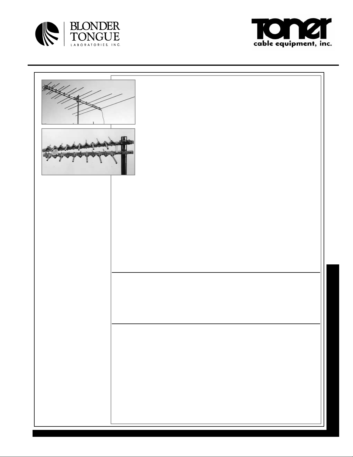
BTY-LP-BB
BROADBAND VHF ANTENNAS
The BTY Broadband Antenna Series includes professional quality, broadband antennas
designed for a variety of VHF and UHF applications. The BTY-LP-BB covers VHF channels 2-6 and 7-13 using 12 antenna elements. The BTY Broadband Antennas feature
high gain, flat response, narrow beamwidth, and low side lobes.
These antennas are designed with a shortened dual boom allowing the antenna to be
shipped via UPS to reduce freight and handling costs. Square boom construction and
end-sealed aluminum elements provide added strength, excellent wind resistance and
exceptional weathering properties. The heavy duty mounting bracket is positioned at
the antenna’s center of gravity for balanced mounting to the mast. This antenna can be
rear mounted using a BTY-C-MOUNT Cantilever Antenna Mount. This style mount permits attaching the antenna to either the horizontal or vertical tower members. The BTY
Series Antennas can accommodate a maximum mast size of 2.5” O.D. (outside diameter). These antennas feature a 75 Ω type “F” connector to provide feed on coaxial cable
down leads. The BTY-LP-BB has been fabricated to allow mounting the BTY-UHF-BB
on the front of the antenna. Joining these two antennas will create one complete
VHF/UHF broadband antenna.
BTY-UHF-BB
BROADBAND UHF ANTENNA
The BTY Broadband Antenna Series includes professional quality, broadband antennas designed for
a variety of VHF and UHF applications. The BTY-UHF-BB covers UHF channels 14-83 using 11
antenna elements. The BTY Broadband Antennas feature high gain, flat response, narrow
beamwidth, and low side lobes.
The heavy duty mounting bracket is positioned at the rear of the antenna for mounting directly to vertical tower members. This feature maximizes the signal reception qualities of the antenna by keeping
the elements clear of support structures. The BTY Series Antennas can accommodate a maximum
mast size of 2.5” O.D. (outside diameter). These antennas feature a 75 Ω type “F” connector to provide feed on coaxial cable down leads. The BTY-UHF-BB has been fabricated to allow mounting on
the front of the BTY-LP-BB antenna. Joining these two antennas will create one complete VHF/UHF
broadband antenna.
SPECIFICATIONS
ELECTRICAL BTY-LP-BB BTY-UHF-BB Units
Gain Over Isotropic: 8.2 10.2 dBi
Bandwidth: 54-88 and 174-216 470-890 MHz
Flatness Over Channel: 1.0 2.0 dB
Horizontal Beamwidth @ -3 dB: 70 62 °
VSWR: 1.67:1 1.67:1
Front to Back Ratio: 18.0 18.0 dB
Return Loss: 12.0 12.0 dB
Impedance: 75 75 Ω
MECHANICAL
Boom: 6063-T6 alum. tube, 6063-T6 alum. tube,
1.25” square, 0.062” wall 0.75” square, 0.062” wall
Boom Length: 96.4 24.0 in
Number of Elements: 12 11
Elements: 6063-T52 alum. tube, 6063-T6 alum. tube,
0.5” round, 0.049” wall 0.375” round, 0.049” wall
Max. Element Width: 114.13 13.00 in
Element 11 gauge 11 gauge alum.
Mounting Clamp: (0.090”) 2.0” x 0.94” (0.090”)
Element Locknut Plate: 8 gauge alum. (0.125”) 8 gauge alum. (0.125”)
Mast Mounting Bracket: polyethylene, 0.50” thickness stainless steel
Turning Radius: 75.0” 22.5”
Maximum Cross Sectional Area: 2.0 0.341 sq. feet
Operational/Survival Wind Velocity: 125 125 mph
Wind Resistance @ 100 mph: 80.0 13.6 (no ice) lbs
Output Connector: Type “F”, female weather sealed Type “F”, female weather sealed
Maximum Mast Diameter (O.D.): 2.5 2.5 in
Shipping Weight: 17.75 (8.07) 5.38 (2.45) lbs (kg)
Shipping Size (LxHxW): 87.5 x 4.0 x 5.5 (222 x 10 x 14) 27.75 x 5 x 15 (70 x 13 x 38) in (cm)
4874
4875
Page 2
Toner Cable Equipment, Inc. Specifications Subject To Change Without Notice.
Telephone: Nationwide: Fax: E-mail: Internet:
BTY SERIES BROADBAND ANTENNAS
215-675-2053 800-523-5947 215-675-7543 info@tonercable.com http://www.tonercable.com
ORDERING INFORMATION:
BTY-2-FM
Stock No. 4878
FEATURES:
Full 88-108 MHz Coverage
360° Beamwidth
Fiber Filled Elements
Dampen Vibration
ORDERING INFORMATION:
BTY-C-MOUNT
Stock No. 5760
FEATURES:
Antenna Cantilever Mount-
Allows Antennas to Mount
Directly to Tower
Maximizes Signal Reception by
Keeping Elements Clear of
Support Structures
Vertical or Horizontal Mounting
BTY-MC
Stock No. 4879
FEATURES:
Stainless Steel Antenna
Mounting Clamp
Allows Stacking of BTY Series
Antennas
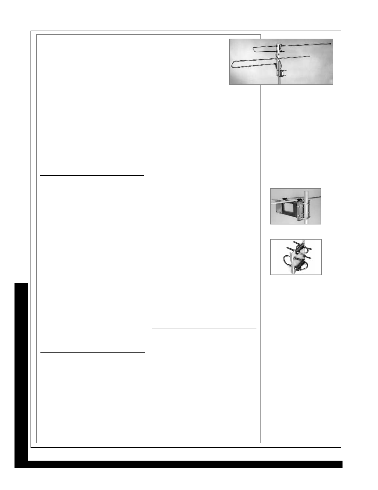
BTY-2-FM
FM ANTENNA
The BTY-2-FM is a professional quality, FM band antenna designed specifically for FM
reception applications. This antenna covers the entire FM band from 88 to 108 MHz
using two half-wave dipole elements mounted 90° to one another. This design give
the BTY-2-FM an omnidirectional (360°) reception path.
The BTY-2-FM is supplied complete with two dipole elements, an 18” square boom,
universal mounting bracket and connector cable. The heavy duty mounting bracket is
designed for either vertical or horizontal tower members and will attach to masts up to 2.5” inches in
diameter. The BTY Series Antennas can accommodate a maximum mast size of 2.5” O.D. (outside
diameter). These antennas feature a 75 Ω type “F” connector to provide feed on coaxial cable down
leads.
5760
4879
SPECIFICATIONS
ELECTRICAL BTY-2-FM Units
Gain Over Isotropic: 2.2 dBi
Bandwidth: 88-108 MHz
Beamwidth (-3 dB): 360° azimuth °
VSWR: 1.67:1
Return Loss: 12.0 dB
Impedance: 75 W
MECHANICAL
Boom: 6063-T6 alum. tube,
1.25” square, 0.062” wall
Boom Length: 18.0 in
Number of Elements: 2
Elements: 6063-T52 alum. tube,
0.5” round, 0.049” wall
MECHANICAL(continued)BTY-2-FM Units
Maximum Element Width: 59.0 in
Turning Radius: 29.0 in
Max. Cross Sectional Area: 0.463 sq. feet
Operational/Survival
Wind Velocity: 125 mph
Output Connector: Type “F”, female,
weather sealed
Max. Mast Diameter (O.D.): 2.5”
Shipping Weight: 3.00 lbs
1.36 kg
Shipping Size: 60 x 4.0 x 5.5 in
(LxHxW) 152 x 10 x 14 cm
BTY-C-MOUNT
ANTENNA MOUNT
The BTY-C-MOUNT consists of a heavy duty
square aluminum boom and all clamping hardware required for rear mounting of the following BTY Series Antennas: BTY-5-LB, BTY-10HB, BTY-LP-LB, BTY-LP-HB, and BTY-LP-BB.
Cantilever end-mounting is commonly used
since the antennas are usually attached to
tower legs rather than to masts. This maximizes the signal reception qualities of the
antenna by keeping elements clear of support
structures. It also eliminates the need for outriggers and masts. Antennas can be mounted
horizontally or vertically on a tower leg or mast
(1.25” to 2.5” O.D.) by rotating the mounting
plate 90°. The BTY-C-MOUNT is designed to
mount parallel to and below the antenna boom.
SPECIFICATIONS
MECHANICAL BTY-C-MOUNT Units
Boom: 6063-T6 alum. tube,
1.25” square, 0.062” wall
Boom Length: 63.38 in
Mounting Plates 14 gauge (0.074”)
and Brackets: stainless steel
Max. Cross
Sectional Area: 0.88 sq. feet
Wind Resistance
(@ 100 mph): 58.2 lbs
Shipping Weight: 8.31 lbs
3.78 kg
BTY-MC
ANTENNA MOUNT
The BTY-MC is a heavy duty, stainless steel
antenna mounting clamp designed for stacking
BTY Series Antennas. The resultant antenna
array improves antenna gain for use in fringe
areas. The BTY-MC has excellent weathering
properties and exceptional strength. The number of clamps needed is dependent on the
number of antennas stacked (i.e. 2 antenna
array uses 3 clamps, a 4 antenna array uses 6
clamps). The BTY-MC is shipped completely
pre-assembled and has a compact design for
ease of mounting.
SPECIFICATIONS
MECHANICAL BTY-MC Units
Material: stainless steel
Mount Dimensions: 6 x 6 x 1.38 in
152 x 152 x 35 mm
U-Bolts:
Quantity: 4
Size: 0.38 in diameter
Maximum Tubing Size: 2.5 in O.D.
Shipping Weight: 2.5 lbs
1.14 kg
4878
 Loading...