

Page 1
Telephone: Nationwide: Fax: E-mail: Internet:
09/04
Force 3005 DBS L-Band Transport Link
215-675-2053 800-523-5947 215-675-7543 info@tonercable.com http://www.tonercable.com
969 Horsham Road
Horsham, Pennsylvania 19044 USA
Model 3005
DBS-L-Band Transport
Model 3005 L-Band Transport Link
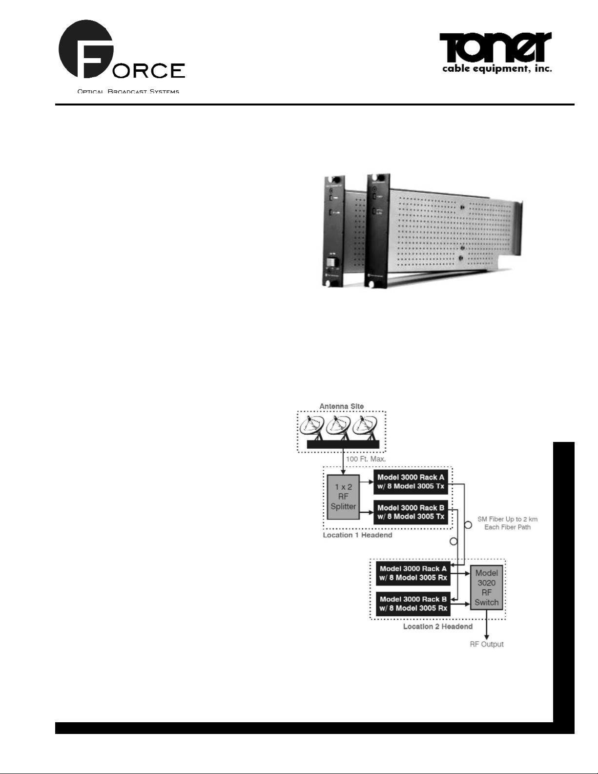
The Model 3005 L-Band Satellite Transport
System provides an economical solution for
transporting digital signals for numerous satellite distribution applications, including headend
relocation. The system utilizes a cost-effective
coax cabling configuration to distribute the RF
signals from the dish to the transmitter and from
the receiver to the headend. The single-mode
optical fiber between the 3005 transmitter and
receiver allows transmission distances to 2 km
at 1310 nm. The transmitter has the ability to
supply LNB power at the remote dish site,
thereby decreasing the need and expense of
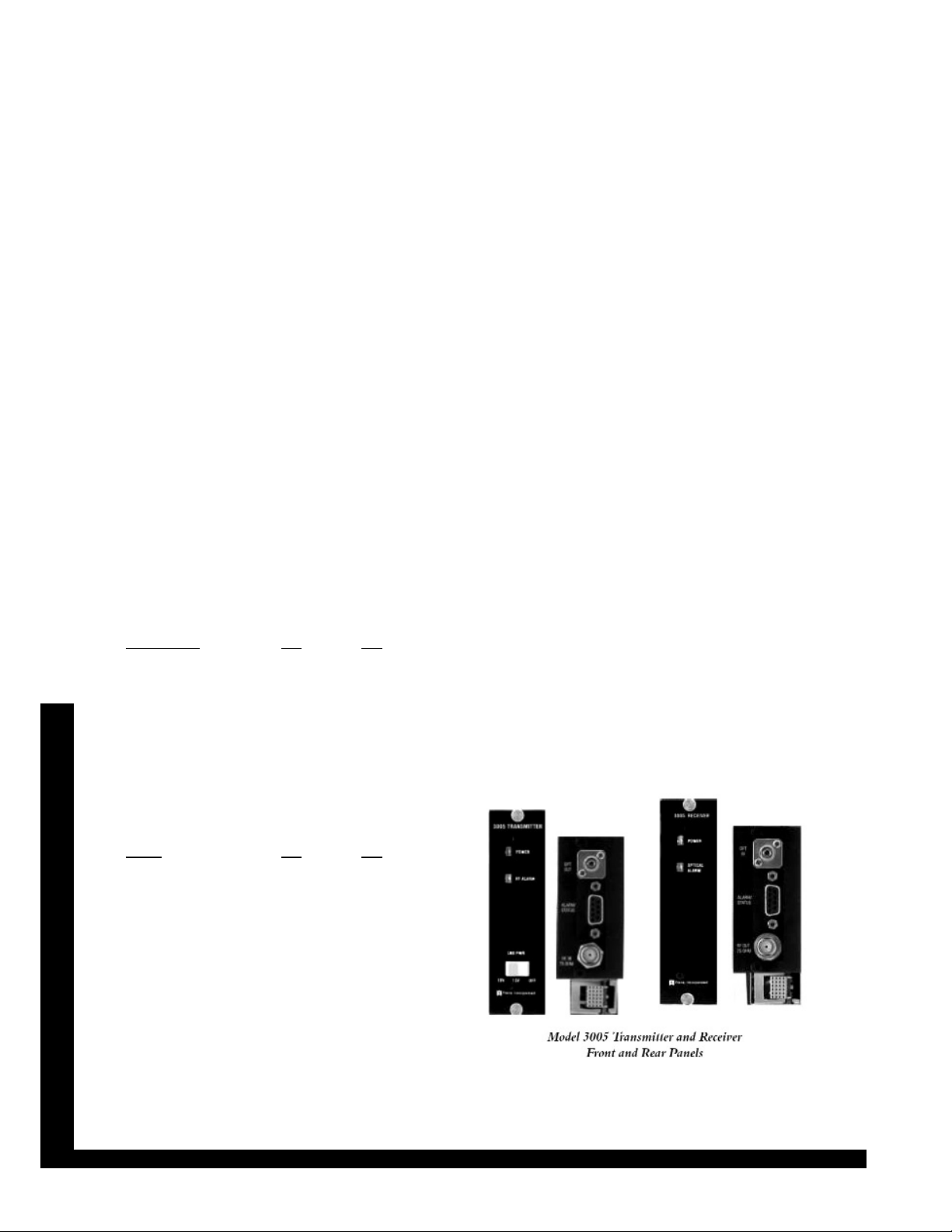
additional equipment. A front panel mounted
switch allows the user to select between +13
Volts and +18 Volts or disable the LNB power.
RF alarm and indicator LEDs allow for quick
assessment of the link’s operational status.
The Model 3005 L-Band Transport System,
whether used in an antenna remoting application or in a satellite distribution role, provides for
transmission of the entire L-Band spectrum in a
simplified, flexible installation environment at
one of the lowest costs found in today’s market.
Features
• Model 3005 transports the full L-Band spectrum (950-2200 MHz) as a standard feature.
• LNB power is user-selectable as +13 Volts,
+18 Volts, or disabled; current limiting technology eliminates down time due to blown
fuses.
• 75 Ohm operation.
• 3RU rack chassis accommodates eight
transmitters and/or receivers and two power
supplies for system reliability.
• System transmits signals up to 2 km and
increases the system’s value for antenna
remoting.
Page 2
Telephone: Nationwide: Fax: E-mail: Internet:
Force 3005 DBS L-Band Transport Link
215-675-2053 800-523-5947 215-675-7543 info@tonercable.com http://www.tonercable.com
©Toner Cable Equipment, Inc. Specifications Subject To Change Without Notice.
Optical and Performance Characteristics
Output Wavelength 1310 nm
Tx Opt Output Pwr (1) +3 dBm
RX Optical Input Power (1,2) -3 to +3 dBm
Optical Loss Range 0-6 dB
I/O Impedance 75 Ohms
CNR (3) 53 dB
RF Gain Variation Over Temp -2 to +2 dB
Link RF Gain (3 dB Opt. Loss) -2 to +2 dB
RF Input Range (4) -35 to 20 dBm
Flatness (full band) ±1.5 dB
Flatness (any 36 MHz) ±0.25 dB
Frequency Range (-3 dB) 950 to 2200 MHz
Return Loss (Tx) 9.5 dB
Return Loss (Rx) 12 dB
1 dB Compression Pt. (Input) -13 dBm
IP2 (+3 dBm Opt. In) +1 dBm
IP2 (-9 dBm Opt. In) +8 dBm
OIP3 (3 dB Opt. Loss) +3 dBm
Noise Figure (3 dB Opt. Loss) 15 dB
Noise Figure (6 dB Opt. Loss) 20 dB
VSWR (Input/Output) 1.6:1
Electrical Characteristics
Power Supply Voltage +20 VDC
Tx Current Draw (5) 150 mA
Rx Current Draw 70 mA
Physical Characteristics
Weight (Tx or Rx) 8 oz, 227 g
Dimensions (Tx or Rx) 5.06 x 1.39 x 12.00 in
129 x 35 x 305 mm
Environmental Characteristics
Operating Temp. Range -40 to +60°C
Storage Temp. Range -40 to +60°C
Humidity (RH, non-condensing) 5 to 95%
(1) All optical power levels are average values.
(2) The receiver contains a tri-colored optical input level LED indicator that
lights green when the proper optical input level is being received.
When the optical input falls below -3 dBm, the LED will turn orange,
and when the optical input exceeds +3 dBm, the LED will turn red.
The receiver also provides an indication of optical input level through
the DB-9 alarm connector, pins 4 and 6. These are open drain outputs
rated for a maximum of +24 volts at 20 mA. An external pull-up resistor is required for output which function as follows:
Optical Input Level
Pin 4 Pin 6
Too Low Low Low
OK Low Open
Too High Open Low
(3) Specification given at 3 dB optical loss, 27 MHz BW, +17 dBmV RF
input level. CNR is measured nominally for 27 MHz bandwidth and
tested at 1 GHz.
(4) The transmitter contains a tri-colored RF input level LED indicator. The
LED will be green when the proper RF level is being input to the transmitter. When the RF falls below optimum, the LED will change to
orange. When the RF level rises above optimum, the LED will change
to red. The transmitter also provides an indication of RF input level
through DB-9 alarm connector, pins 4 and 6. These are open drain
outputs rated for a maximum of +24 Volts at 20 mA. An external pullup resistor is required for each output. The outputs function as follows:
RF Level
Pin 4 Pin 6
Too Low Low Low
OK Low Open
Too High Open Low
(5) The maximum current draw specification is based on the transmitter
providing LNB power.
Short Range Tx and Rx P/N
3005 Tx and Rx Options SC/APC Conn. FC/APC Conn.
Tx, 75 Ohm, 1310 nm, LNB Pwr. 3005TA-SCSP 3005TA-SFAP
Rx, 75 Ohm, 1310/1550 nm 3005RA-SFSP 3005RA-SFAP
3RU Chassis and all Power Supplies
Chassis, Power Supply and Panel Options
3RU Chassis, Holds 8 Modules and 2 P.S. 3000CB-NN
3RU Power Supply, Universal AC 3000UC-NN
3RU Blank Panel for Unused Module Slots (optional) 3000EA-NN
3RU Blank Panel for Unused P.S. Slot (optional) 3000EB-NN
 Loading...