

Tone King

1
User’s Manual
Note from the Builder
Thank you for choosing Tone King’s Ironman II precision power attenuator. The
Ironman II is a new generation of power attenuator, with a sophisticated design that
preserves the tone and feel of your amplifier quite well, while reducing the volume level
at the speakers.
There are two important components to the Ironman II design that make it unique and
particularly effective - the tuned reactive load and the transformer coupled power
division circuitry.
The idea was that the load seen by the amplifier should always have the appropriate
complex impedance curve so that it responds as it does to a real speaker load. A real
speaker load varies greatly with frequency. For example, the impedance of a typical "8
ohm" speaker may rise to 60 ohms or more at its resonant frequency (usually around
60-80Hz), and then rise again to many tens of ohms at high frequencies. An amplifier
responds a lot differently when driving a complex load like this, compared to a simple
resistive load (as is used in most attenuators). We developed the Ironman II's reactive
load circuit by matching the results of impedance curve measurements we ran on an
actual speaker in typical cabinet. The resulting design was then tweaked through
empirical methods, in order to create a load circuit that is most effective at preserving
the tone and feel of your amplifier.
The second part of the equation is the circuitry that divides the power from your
amplifier between the speaker and the load. In other attenuators, this is often done
with a resistor ladder. There are two problems with this approach - first, the resistor
ladder itself can become part of the load, which means that the amplifier sees a simple
resistive load. Second, in dividing the power this way, a voltage divider is effectively
formed between the dividing network and the speaker. Since the speaker has a
complex impedance that varies with frequency, the result is that the frequency response
at the speaker is altered, usually dulling the top end and muddying the sound.
The scheme we chose involves 100% transformer coupling, using a set of custom
transformers, so that the connection between the amplifier to load, and between the
amplifier to speaker, is purely transformer coupled at every step of the attenuation dial.
This is an expensive and elaborate design (each step of the dial requires its own tap on
one of the custom transformers), but is significantly more effective at preserving the
tone and feel of your amplifier more than other methods.
In this new Iron Man II design, we added an analog speaker cabinet simulation for DI
purposes (balanced XLR). Included is a level switch (line and microphone inputs), an
option to select between speaker center or edge micing and a ground-lift to avoid
ground loops in conjunction with other equipment.

2
Safety Instructions (Important !)
Please keep this instruction manual for future reference and for the duration of owning
this Tone King product. Please carefully read and understand the instructions inside
this user’s manual before attempting to operate your new amp. This instruction manual
includes essential safety information regarding the use and maintenance of the
amplifier. Take special care to heed all warning symbols and signs inside this manual
and those printed on the amplifier itself.
WARNING!
TO PREVENT FIRE OR SHOCK HAZARD, DO NOT EXPOSE THE AMPLIFIER TO
WATER OR MOISTURE. DO NOT OPERATE NEAR ANY WATER SOURCE
WHAT’S THE MEANING OF THIS?
The lightning flash with an arrow triangular symbol is intended to alert the user to the
presence of non-insulated “dangerous voltage” within the products enclosure, and may
be of sufficient magnitude to constitute a risk of electric shock
WHAT’S THE MEANING OF THIS?
The exclamation point triangular symbol is intended to alert the user to the presence of
important operating and maintenance (servicing) instructions in the user manual
accompanying this amplifier!
1. Read Instructions – All the safety and operating instructions should be read before
this product is operated.
2. Retain Instructions – The safety and operating instructions should be retained for
future reference.
3. Heed Warnings – All warnings on the amplifier and in the operating instructions
should be adhered to.
4. Follow Instructions – All operating and use instructions should be followed.
5. Water and Moisture – The amplifier should not be used near water – for example, a
bathtub, washbowl, kitchen sink, laundry tub, wet basement, or near a swimming pool,
and the like.
6. Heat – Amplifier should be situated away from heat sources such as radiators, heat
registers, stoves, or other amplifier (including amplifiers) that produce heat.
7. Power Sources – This product should be operated only from the type of power source
indicated on the rating label.
If you are not sure of the type of power supply to your home, consult your product
dealer or local power company.
8. Grounding or Polarization
– This product may be equipped with a polarized alternation-current line plug (a plug
having one blade wider than the other). This plug will fit into the power outlet only one
way. This is a safety feature. If you are unable to insert the plug fully into the outlet, try

3
reversing the plug. If the plug should still fail to fit, contact your electrician to replace
your obsolete outlet. Do not defeat the safety purpose of the polarized plug.
9. Power-Cord Protection
– Power-supply cords should be routed so that they are not likely to be walked on or
pinched by items placed upon or against them, paying particular attention to the cord
in correspondence of plugs, convenience receptacles, and the point where they exit from
the amplifier.
10. Cleaning – The amplifier should be cleaned only as recommended by the
manufacturer. Clean by wiping with a cloth slightly damp with water. Avoid getting
water inside the amplifier.
11. Non-use Periods – The power cord of the amplifier should be unplugged from the
outlet when left unused for a long period of time.
12. Object and Liquid Entry
– Care should be taken so that objects do not fall and liquids are not spilled into the
enclosure through openings.
13. Damage Requiring Service
– The amplifier should be serviced by qualified service personnel when:
A. The power-supply cord or the plug has been damaged; or
B. Objects have fallen, or liquid has been spilled into the amplifier; or
C. The power attenuator has been exposed to rain; or
D. The power attenuator does not appear to operate normally or exhibits a marked
change in performance; or
E. The power attenuator has been dropped, or the enclosure damaged.
F. The power attenuator needs tube replacement or biasing
14. Servicing – The user should not attempt any service to the power attenuator beyond
that described in the operating instructions. All other servicing should be referred to
qualified service personnel.
15. Ventilation – Slots and openings in the cabinet are provided for ventilation and to
ensure reliable operation of the product and to protect it from overheating, and these
openings must not be blocked or covered.
16. Attachments – do not use attachments not recommended by the product
manufacturer as they may cause hazards.
17. Accessories – Do not place this product on an unstable cart, stand, tripod, bracket,
or table. The product may fall, causing serious injury to a child or adult, and serious
damage to the product. Use only with a cart, stand, tripod, bracket, or table
recommended by the manufacturer, or sold with the product.
18. Lightning – For added protection for this product before a lightning storm, or when
it is left unattended and unused for long periods of time, unplug it from the wall outlet.
This will prevent damage to the product due to lightning and power line surges.
19. Replacement Parts – When replacement parts are required, be sure the service
technician has used replacement parts specified by the manufacturer or have the same
characteristics as the original part. Unauthorized substitutions may result in fire,
electric shock, or other hazards.

4
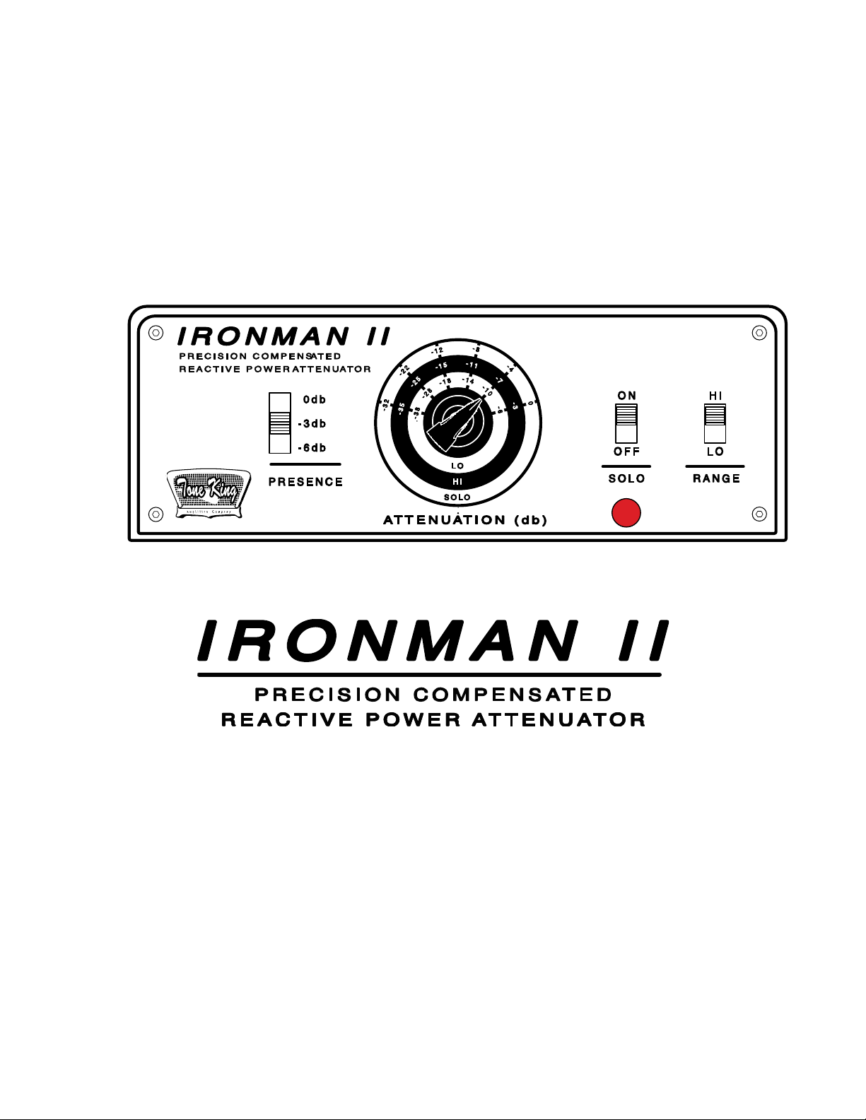
1. Front Panel Controls
5 Presence / Solo / Range Switch
5 Attenuation Knob
5
2. Back Panel Controls
7 Amplifier Input
7 Speaker Connections
7
Line Out
DI Output
8
8
3. Using the Ironman II
8 Purpose
8 Impedance Matching
8 Adjusting the Controls
8 Use as a Dummy Load
8 What to Expect When Attenuating
9
4. Warranty
11-12
Contents

5
1. Front Panel Controls
Presence Switch
The Presence switch provides subtle control of brightness and compression. It allows
you to tailor the response to match your acoustic environment, and to correct for an
overly bright amplifier. Three settings are provided: 0db (brightest setting), -3db, and
-6db (darkest setting).
Attenuate / Bypass Switch
There is no Bypass switch. The “Bypass” mode, which is in fact not called ‘bypass’ is the
far right setting of the attenuation knob (0dB) in the Solo mode
This switch (see above) allows you to completely bypass the attenuator. In Attenuate
mode, the attenuator is active, and in Bypass mode, the attenuator is disabled.
Because of this, the impedance matching switches (on the back panel) have no effect in
Bypass mode.
Important - do not toggle the Attenuate/Bypass switch while playing through your
amplifier. Dampen the strings of the guitar while toggling this switch.
Attenuation Knob & Range Switch
The Attenuation knob determines the amount of power sent to the speaker. At 0db, the
signal is not attenuated, and all of the power from the amplifier is sent to the speaker.
The maximum possible attenuation is -38db. At this setting, nearly all the power from
the amplifier is dissipated in the Ironman II, and very little is sent to the speaker. At
this setting, you can safely unplug the speaker, and use the Ironman II as a dummy
load.
Important - do not adjust the Range or Attenuation controls while playing
through your amplifier. Dampen the strings of the guitar while adjusting these
controls.

6
You'll notice that the Attenuation dial is split into three ranges at the right side of the
knob. The Range switch selects between these two ranges, as follows:
Solo Switch ON: 0-32db setting
The attenuation values shown at left in red are available when the Range switch is in
the 0-32db position.
Range Switch HI: -3-35db setting (Solo Switch OFF)
The attenuation values shown in red are available when the Range switch is in the -335db position.
Range Switch LO: -6-38db setting (Solo Switch OFF)
The attenuation values shown in red are available when the Range switch is in the -638db position.

7
2. Back Panel Controls
Amplifier Input
The amplifier should be connected to the Ironman II's Amplifier input with a standard
1/4" speaker cable. The Amplifier Impedance switch should be set to match the
impedance of the amplifier.
For a proper Wattage matching set the Ironman II's Amplifier Impedance switch to
match the impedance selected on your amplifier.
Speaker Connections
Two speaker jacks are provided for connecting speakers to the Ironman II. Both
speaker jacks are wired in parallel. If you are only connecting one speaker to the
Ironman II, you can use either jack.
The Speaker Impedance switch should be set to match the total combined impedance of
the speaker(s) connected to the Ironman II. If you are connecting a single speaker to
the Ironman, simply set the Speaker Impedance switch to match that speaker's
impedance.
If you are connecting two speakers to the Ironman II, it is best to use two speakers with
the same impedance. If you do this, then the total combined impedance will be 1/2 of
each speaker's impedance. Here are a few examples of how to set the Ironman when
using two speakers:
- If you are connecting TWO 8-ohm speakers to the Ironman II, using the two Speaker
jacks provided, then you should set the Speaker Impedance switch to 4 Ohms.
- If you are connecting TWO 16-ohm speakers to the Ironman II, using the two Speaker
jacks provided, then you should set the Speaker Impedance switch to 8 Ohms.
Foot Switch
Connect the provided footswitch to the “FOOTSWITCH” jack to toggle the Solo option on
and off. According to page 3 the Solo function selects between the Solo and Lo/Hi range
setting and therewith provides the possibility to play with 2 different volume levels. This
is useful for giving the guitar that extra volume kick needed for a Solo to cut out in the
mix but it can also be handy to simply have 2 rhythm volume settings.
DC-12V
Connect the provided 12V (1A; 2.1mm; minus center) or any other power supply which
meets this specs here.

8
Line Out
The Ironman II's Line-Out jack provides a line-level signal that can be used to drive
another amplifier, mixing board, computer sound input, or any other line level input.
The specs for this output signal are as follows:
• Output Level: approx. 0 - 1V p/p level controlled indirectly through the level of
the amplifier
• Impedance: 10K Ohms
• Interface: Unbalanced, mono 1/4" connection
The adjustable level control allows you to control the level of the line-out signal. This is
useful if the Line-Out is being used to drive another guitar amplifier, where you need to
reduce the level to avoid overdriving the guitar amplifier.
The line-out signal is generated from the amplifier input, and does not change as you
vary the attenuation knob. The line-out signal will be present even when the attenuator
is bypassed.
The line-out signal is a non speaker simulated output.
DI Output
In this new design Iron Man II design we included a cab-simulated (OP amp driven)
balanced XLR output XLR output. Comparing this analog circuit to some of the most
intricate computer-based IRs, we achieved a great sounding output you can send to
front of house or use in the studio. The XLR output includes a ground-lift, level, and
center/edge of speaker cone simulation switches.
BALANCED OUTPUT: XLR output used to send your Iron Man tone straight to the
mixing board.
GND SWITCH: The ground lift switch lifts Pin 1 of the XLR output jack from the Iron
Man’s ground to avoid ground loops when connected to equipment such as an audio
interface or mixing desk. Start with placing in LIFT position.
AXIS SWITCH: Simulates MIC placement on the center of the speaker or the
cone/edge, whereas cone offers more top end than edge. Adjust to your liking.
LEVEL SWITCH: the level switch provides either -10 or -30dB for a proper level
matching with an external audio interface or mixing desk.

9
3. Using the Ironman II
Purpose
The Ironman II precision attenuator allows you to reduce the volume level at the
speaker(s) while allowing the amplifier to operate at full output power, for natural power
tube overdrive and distortion. The Ironman II allows you to select the amount of the
amplifier's output power that is sent to the speakers, with the rest of the power being
dissipated within the Ironman II.
Impedance Matching
One unique feature of the Ironman II is its dual Impedance controls - one for the
amplifier input, and one for the speaker output. These dual impedance controls allow
you to match your speaker to your amplifier, even if the speaker impedance differs from
the amplifiers' output impedance.
You can even perform this matching without attenuating. To do this, simply set the
attenuation knob to 0db, and make sure the Attenuate/Bypass switch is in the
Attenuate setting. Then, set the Amplifier Impedance switch and the Speaker
Impedance switch as appropriate to match the speaker to the amplifier.
Adjusting the Controls
When adjusting any of the front or back panel controls, it's best to dampen the strings
of your guitar, so that no significant amount of signal is being generated by the
amplifier.
Use as a Dummy Load
The Ironman II may be used as a dummy load, to provide a proper load for your
amplifier, with no speakers attached. This is typically done in recording, where the
Ironman II's Line-Out will be used to drive a mixing board, or when an amplifier is
being "slaved" to a larger amp (with the Line-Out signal driving another amplifier).
Here's how to set the Ironman II when using it as a dummy load:
• Attenuation Control: -38db
• Solo Switch: OFF
• Range Switch: LO
• Amplifier Impedance Switch: set to match amplifier output impedance
• Speaker Impedance Switch: setting doesn't matter
• Nothing plugged into the Speaker jacks

10
What to Expect When Attenuating
Although the Ironman II attenuator does an excellent job of reducing output power
without changing the tone of the amp’s circuitry, there are other variables in play at
lower volume which do result in some apparent tone change. Here are a few factors
that you should be aware of:
Speaker breakup and compression is a big part of the tone and feel of the amp when
played at high volume. At low power settings, the speaker responds differently, and
does not break up and compress as it does at high power.
The ear’s natural response curve varies at different volume levels, which changes the
way you perceive sounds at different volume levels. Quieter sounds tend to give the
impression of having less bass content.
At lower volume, there is a tendency to hit the guitar strings harder and play more
aggressively than you would if the amp were tuned up very loud. It may take some time
to get used to maintaining your playing style at reduced volume.

11
TONE KING LIMITED WARRANTY
Tone King manufactures some of the world’s most reliable hand-wired, all-tube
amplifiers, speaker cabinets and Power Attenuators. Tone King takes great pride in an
extremely thorough testing procedure which is implemented on each product prior to
shipment. In the unlikely event that you have a problem with your the Iron Man II,
please refer to warranty below. Tone King stands behind our products like no other and
we’re here to help you!
Power Attenuators: Tone King offers a limited 5 Year warranty to the original purchaser
that a Tone King power attenuator will be free from defects in material and
workmanship. A dated sales receipt will establish coverage under this warranty,
PLEASE KEEP YOUR PROOF OF PURCHASE TO USE YOUR WARRANTY. This warranty
does not cover service or parts to repair damage caused by accident, neglect, abuse,
normal & wear, disaster, misuse, abuse, over-powering, negligence, inadequate packing
or shipping procedures and service, repair or any modifications to the product which
have not been authorized or approved by Tone King in writing. ANY MODIFICATION TO
THE POWER ATTENUATOR WILL VOID YOUR WARRANTY. If this product is defective
in materials or workmanship as warranted above, your sole remedy shall be repair or
replacement by Tone King as provided below.
CAUTION: Do NOT attempt to repair, modify or service your power attenuator by
yourself!!! Please read the instruction manual for all safety notifications, warnings and
instructions. Tone King power attenuators, have extremely high voltages that can
cause serious injury or death. Do not remove the chassis from the power attenuator.
All repair and service work must be performed by Tone King or an authorized service
center of Tone King. ANY UNAUTHORIZED REPAIRS WILL VOID YOUR WARRANTY.
RETURN PROCEDURES: In the unlikely event that a defect occurs please call us at
323-277-4100. In most cases we can help you diagnose the problem over the phone. If
a product must be sent to us, please follow the procedure outlined below.
Defective products must be shipped, together with proof of purchase, freight pre-
•
paid and insured to the Authorized Tone King Service Center or directly to Tone
King.
If a product must be returned to Tone King for warranty replacement/repair, a
•
Return Authorization Number must be obtained from our Customer Service
Department prior to shipping the product.
Please contact Tone King Customer Service Department for the Authorized Tone
•
King Service Center nearest you.
Products must be shipped in their original packaging or its equivalent; in any
•
case, the risk of loss or damage in transit is to be borne by the purchaser.
The Return Authorization Number must appear in large print directly below the
•
shipping address.
Always include a brief description of the defect, along with your correct return
•
address and telephone number.
When calling to inquire about a returned product, always refer to the Return
•
Authorization Number.
If Tone King determines that the unit was defective in materials or workmanship at any
time during the warranty period, Tone King has the option of repairing or replacing the
product at no additional charge, except as set forth below.
All replaced parts become a property of Tone King. Products replaced or repaired
•
under this warranty will be returned via ground shipping within the United
States or Canada - freight prepaid.

12
Tone King is not responsible for costs associated with expedited shipping, either
•
to Tone King or the return of the product to the customer.
All warranty repairs outside the United States and Canada must be directed to the
dealer or distributor from which you purchased the product.
INCIDENTAL OR CONSEQUENTIAL DAMAGE: In no event will Tone King be liable for
any incidental or consequential damages arising out of the use or inability to use of any
Tone King product, even if a Tone King dealer has been advised of the possibility of
such damages, or any other claim by any other party. Some states do not allow the
exclusion or limitation of consequential damages, so the above limitation and exclusion
may not apply to you. This warranty gives you specific legal rights and you may also
have other rights which may vary from state to state.
FOR YOUR PROTECTION: Please complete the warranty registration online at
www.toneking.com within (10) ten days of the date of purchase so that we may contact
you directly in the event a safety notification issued in accordance with the 1972
Consumer Product Safety Act.
CUSTOMER SUPPORT: Our dedicated and friendly staff is ready to help you with any
warranty or product questions you may have. Please call us at 323-277-4100 – Monday
– Friday 9AM-4PM (Pacific Standard Time)
Thank you again for choosing Tone King and we look forward to a long relationship!
www.ToneKing.com
 Loading...