

TONAZZI COLIBRI’ 601 User Manual

3
COLIBRI’ 601
MACCHINA INTUBETTATRICE
QUADRI COMANDO E/O PANNELLI DI CONTROLLO
CLIENTE:
CUSTOMER:
TUBE FILLING MACHINE
COMMAND AND/OR CONTROL PANEL
BODY’N SCENTS INC.
MATRICOLA N°:
SERIAL N°:
502000019


3
Sede Amministrativa / Registered Administrative Office: Via Kennedy, 2/4 - 20023 CERRO M. (MI) ITALIA
Tel: (0331) 514356 - Fax (0331) 515671
COLIBRI’ 601
/
MACCHINA INTUBETTATRICE / TUBE FILLING MACHINE
QUADRI COMANDO E/O PANNELLI DI CONTROLLO / COMMAND AND/OR CONTROL PANEL
CLIENTE:
CUSTOMER:
MATRICOLA N°:
SERIAL N°:
Manuale redatto in conformità con la direttiva 98/37/CE.
Realizzato dal Dipartimento Documentale (Redazione/Grafica) della Marchesini S.p.A. in collaborazione con la
Direzione Tecnica Progettuale.
Traduzioni realizzate con la collaborazione della Agenzia Intracoop S.c.r.l., Società di Traduzioni operante in conformità
UNI EN 29002 (ISO 9002)
Manual drawn up in conformity with EEC directive 98/37/EC.
Created by the Marchesini S.p.A. Documentation Department (Editing/Graphic) in collaboration with the Technical
Design Department.
BODY’N SCENTS INC.
502000019
Translated in collaboration with Intracoop S.c.r.l., a translation company which operates in conformity with UNI EN
29002 (ISO 9002)
Codice Manuale: 502000019-1-1
Manual Code:
Ultima data di stampa: 15/04/03
Date of final print: Total N° of pages:
N° pagine totali: 17


USER MANUAL
Operating instructions and specifications . . . . . . . . . . . . . . . . . A-1
Machine Process Cycle . . . . . . . . . . . . . . . . . . . . . . A-1
Control panel . . . . . . . . . . . . . . . . . . . . . . . . . . A-2
Display . . . . . . . . . . . . . . . . . . . . . . . . . . . . . B-1
Description . . . . . . . . . . . . . . . . . . . . . . . . . . . B-1
Description Of Controls . . . . . . . . . . . . . . . . . . . . . . . B-2
Program Structure . . . . . . . . . . . . . . . . . . . . . . . . B-3
Main Menu . . . . . . . . . . . . . . . . . . . . . . . . . . . B-4
Selections . . . . . . . . . . . . . . . . . . . . . . . . . . B-5
Functional selectors . . . . . . . . . . . . . . . . . . . . . . . B-6
Key selector . . . . . . . . . . . . . . . . . . . . . . . . . B-7
Parameters change . . . . . . . . . . . . . . . . . . . . . . . B-8
Semiautomatic adjustment . . . . . . . . . . . . . . . . . . . . . B-9
Operating size setting . . . . . . . . . . . . . . . . . . . . . . B-10
Menu . . . . . . . . . . . . . . . . . . . . . . . . . . . . . B-11
Message Language Selection . . . . . . . . . . . . . . . . . . . . B-12
Size configuration . . . . . . . . . . . . . . . . . . . . . . . . B-13
Production data . . . . . . . . . . . . . . . . . . . . . . . . B-14
Resetting counters . . . . . . . . . . . . . . . . . . . . . . B-14
Machine states . . . . . . . . . . . . . . . . . . . . . . . . B-15
Service menu . . . . . . . . . . . . . . . . . . . . . . . . . B-16
Maintenance . . . . . . . . . . . . . . . . . . . . . . . . B-17
Functional selectors Continued .... . . . . . . . . . . . . . . . . . . . C-1
Key selectors Continued .... . . . . . . . . . . . . . . . . . . . . . D-1
Parameters Change Continued .... . . . . . . . . . . . . . . . . . . . E-1
INDEX
PAGE 1

Marchesini Group
This page has been left deliberately blank
PAGE 2

Operating instructions and specifications
Machine Process Cycl e
A feed unit deposits a bottle in each bucket on the product chain conveyor.
The presence of the product enables pick-up of the carton and the leaflet.
The product and the leaflet are inserted in the carton by the pushers.
The cartons are then closed.
If there is no carton or no leaflet, the c ontent of the tray is r ejected.
USER MANUAL
PAGE A-1
PART A
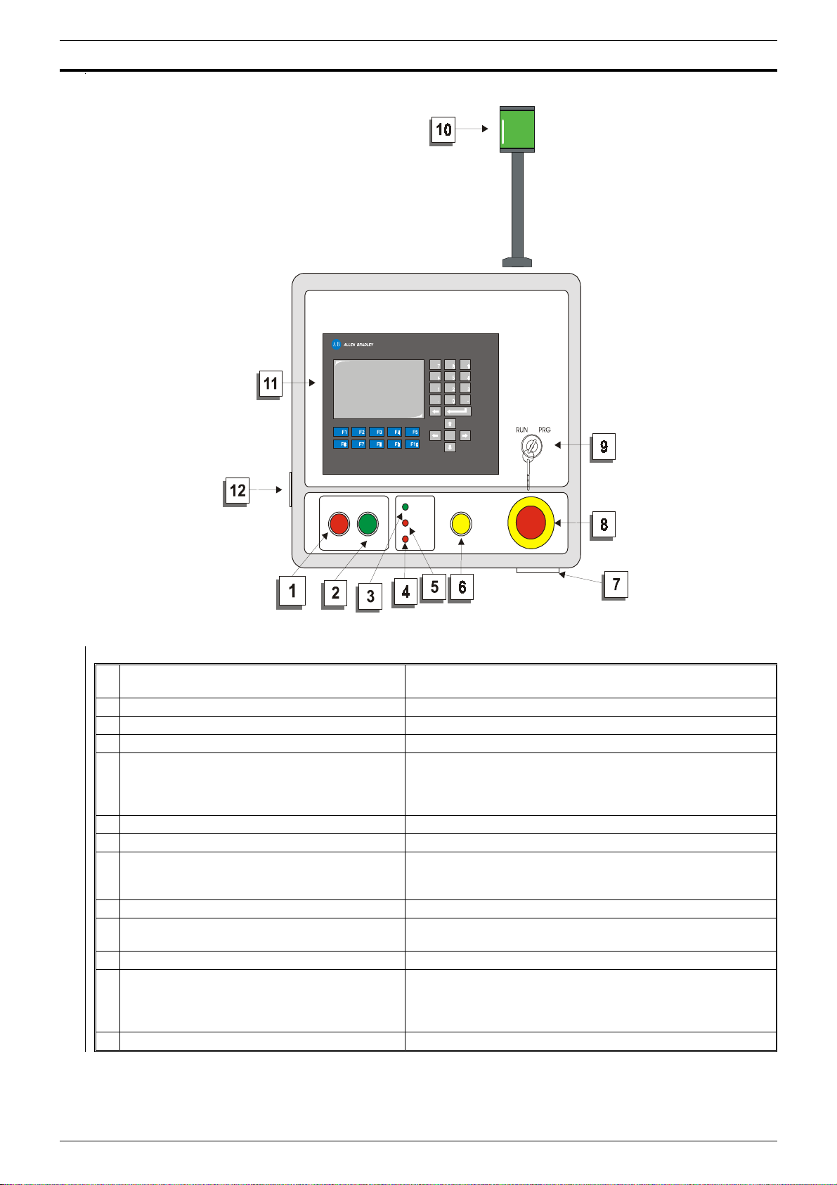
Control panel
Stop pushbutton
1
Start pushbutton
2
Power on led
3
CPU fault warning led When lit this indicates a P LC operating fault.
4
Communication error warning led
5
Reset pushbutton This acts as a safety device reset pushbutton
6
Acoustic alarm
7
Emergency stop pushbutton machine
8
Programming key
9
Machine automatic restart service/running
10
warning light
Display
11
Jack plug socket
12
Main switch
12
If pressed for longer than 3 seconds this pushbutton will
also perform a lamp test.
Fix: fault in the communication between display and PLC.
Data trasmission retry.
Flashing: display results disconnected.
Check the electrical connection.
In the event of an emergency press thi s pushbutton to
immediately stop all those motor s which might constitute
a danger for the operator.
When the remote control jack is plugged into this socket
the machine cannot be started from the main control
panel and the safety switches of the control circuit are
disenabled.
PAGE A-2

PARTE B Allen Bradley
Display
Description
The primary function of the control panel i s to facilitate the operator’s tasks by displaying machine status and
stoppage messages on the control panel display.
This approach has made it possible to dispense with a large number of warning lights and LED. The display
of status and stoppage messages enables rapid diagnosis of machine conditions and therefore more rapid
operator intervention.
The control panel also provides access to a series of menus for managing machi ne configuration, and other
functions.
The displays shown in the pages which follow are intended as examples only.
The processing program is tailored to customers’ individual requirements and as a consequence the displays on your
equipment might vary from those shown in the examples which follow.
Data interchange takes place over an All en Bradley DH+ protocol.
PAG. B-1
Allen Bradley PARTE B
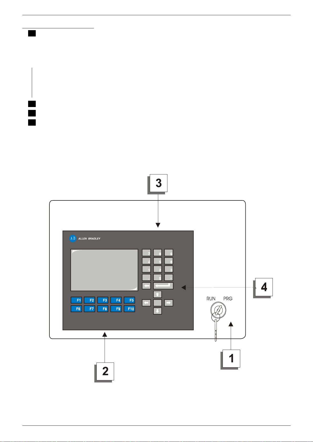
Description Of Controls
Programming key
1
All those functions which require insertion of the programming key will modify machine functioning. Turning the key
to the "PRG" position immediately stops the machine.
In order to prevent accidental or unauthorised use, do not leave the programming key inserted when not in use. The
programming key must only be used by authorised, qualified personnel.
To access programming functions (e.g. modifying parameters, other function), insert the programming key
and turn it to the "PRG" position.
When you turn the programming key to the "PRG" position, the message "Programming On" will be
displayed. In this position, the machi ne will remain stopped and wait for data entries from the control panel.
To restart the machine, turn the programming key to the "RUN" pos ition.
Function keys: allow access to s ub-menus and entry of machine func tions. (from F1 to F10)
2
Numeric keyboard
3
Confirm key (ENTER)
4
PAG. B-2
 Loading...