


CONTENTS
1. Introduction ........................................... 1
Checklist ........................................ 2
Recommended Accessories ........... 3
Overhead Diagram ........................ 4
Back Panel Diagram ...................... 5
LCD Display ..................................... 5
2. Keyboard Layout ................................... 6
From Piano to Plexus ..................... 6
Default Master Tuning .................... 7
Octaves and Fifths ......................... 7
Commas and JNDs ........................ 8
Key Diameter and Elevation ........... 8
3. Tuning Tables ........................................... 9
MIDI Mapping ................................... 9
Untuned Output Mode ...................... 10
Duplicate Keys ................................. 10
Programming a Tuning .................... 11
Local Control Switch ...................... 11
Octave Buttons ................................ 11
4. Polyphony .............................................. 11
5. Presets .................................................... 12
Storing a Table Preset ..................... 13
Storing a Patch Preset ..................... 13
6. Live Control ............................................ 14
Switches and Control Groups ......... 14
Hex Display ...................................... 15
Waveform Group (AC) ..................... 16
Equalizer Group (BC) ...................... 17
Effect Group (AD) .................................. 18
Modulation / Pitch Bend Group (BD) ..... 19
7. Joystick Option ............................................. 21
8. External MIDI Devices .................................. 22
Controllers ............................................ 22
Standard External Modules .................. 22
Natively Microtonal External Modules .. 22
Startup Sequence ................................. 23
9. Sequencer / MIDI Footswitch Control ......... 23
Patch Changes ...................................... 23
Bank Select .......................................... 23
Tuning Table Changes .......................... 24
10. DIP Switches .............................................. 25
Bank Select Format .............................. 25
Velocity Randomization Bandwidth ...... 26
Pitch Bend Response Timing ............... 26
Sysex Retransmission .......................... 27
Global Pitch Bend Mode ....................... 27
Sustain Pedal Polarity ........................... 28
Sysex Recovery Timing ......................... 29
APPENDIX ........................................................ 30
General MIDI Patch List ....................... 30
Hexadecimal Values .............................. 32
MIDI Implementation Chart .................... 33
System Exclusive Messages ................ 34
Troubleshooting ..................................... 35
Technical Specification .......................... 38

1. Introduction
The H-Pi Instruments Tonal Plexus TPX6s/8s is a hand-made instrument designed to be lightweight,
easy to use, and compatible with the widest range of existing MIDI hardware and software, allowing
easy exploration of the limitless universe of alternative tunings. Please refer to this manual to get the
most out of your keyboard.
Your input is appreciated. If you have a question or comment about something in this manual, or
something which is not addressed in this manual, please contact H-Pi Instruments via email at
contact@h-pi.com. In response to your input, this manual may be updated and made available for
PDF download from the H-Pi Instruments website at www.h-pi.com/downloads.html.
This manual was uploaded July 17, 2008 and is the first version of theTPX6s/8s manual. This manual
may be replaced at any time by another manual.
!" INSTRUMENTS www.h-pi.com · T O N A L P L E X U S T P X 6s/8s · User Manual 1
Checklist
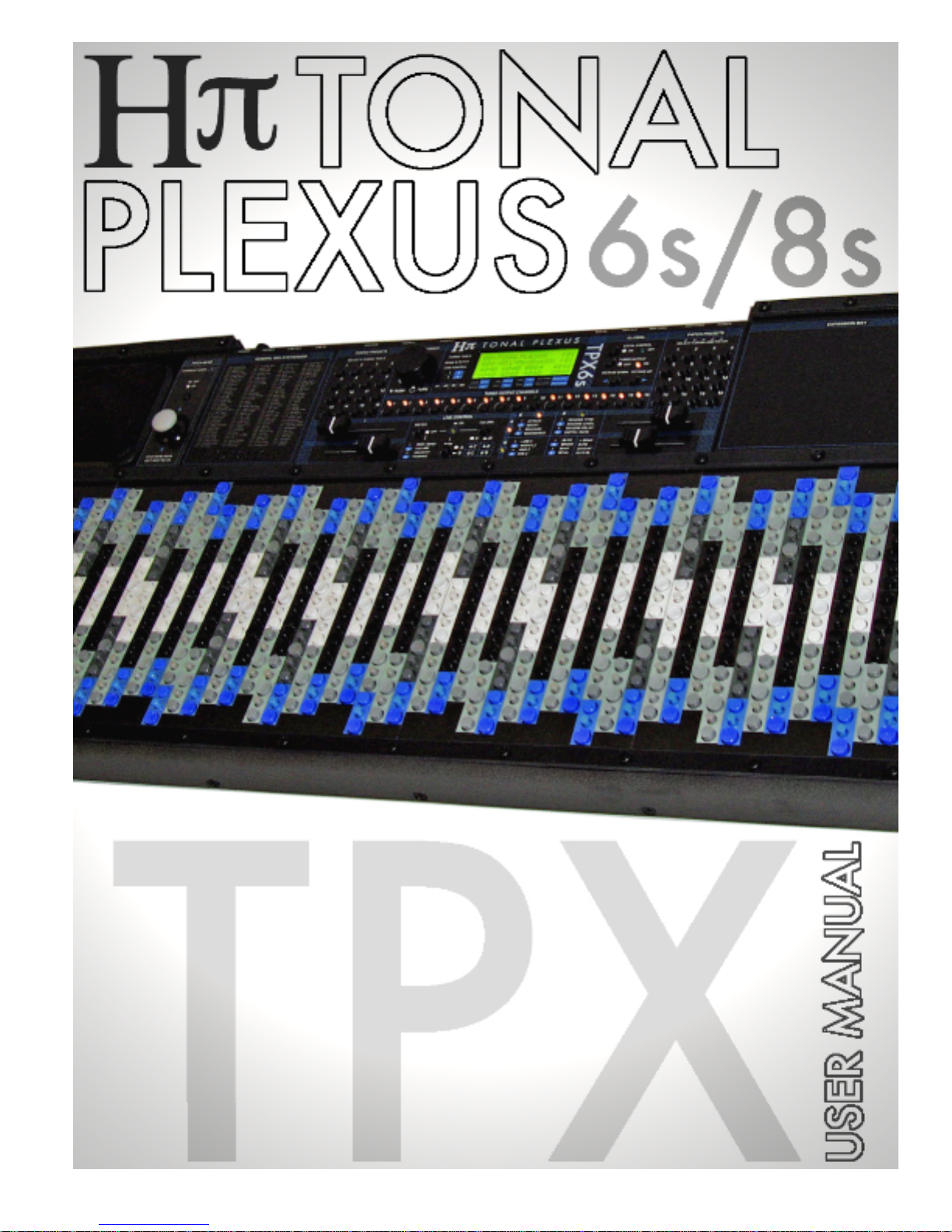
TPX6s/8s
Every TPX6s/8s unit is built by hand. Please do not be alarmed by any small blemishes you may find.
Always handle the unit with care.
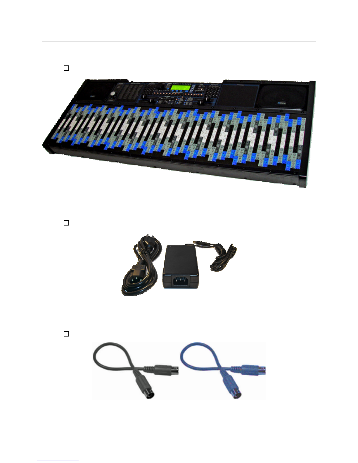
International 12V 4.5A Power Supply
The power supply runs on 100 - 240V, 50 - 60Hz, and will work in most countries around the world –
just plug in a locally supported grounded cable (US standard cable shown above, left) or adapter.
Two MIDI cables (optional)
Having these items, you are ready to begin.
!" INSTRUMENTS www.h-pi.com · T O N A L P L E X U S T P X 6s/8s · User Manual 2
Recommended Accessories
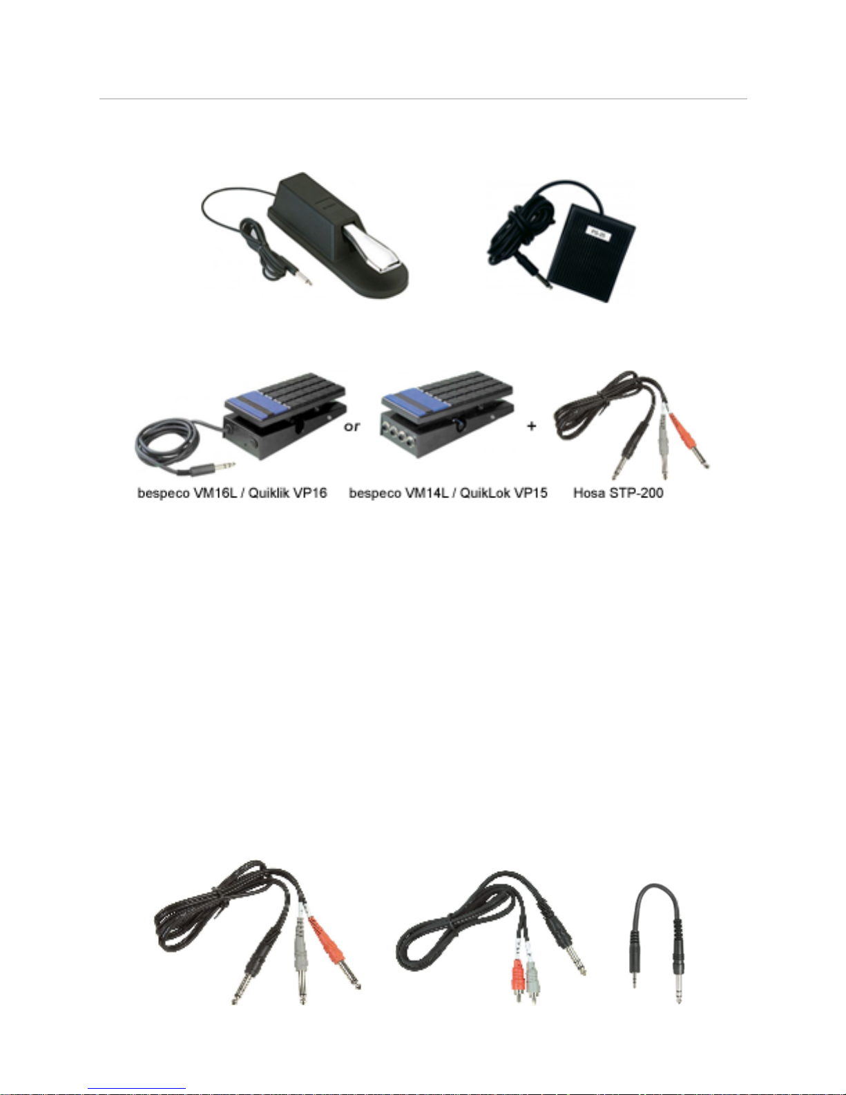
Sustain Pedal
Because TPX6s/8s has a sustain pedal polarity switch, all sustain pedals are compatible.
Volume Pedals
Volume pedals may be used to override top panel faders 2 and 3. The pedal should be 20KOhm.
High impedance guitar volume pedals will work, but not very well. The volume pedal we recommend is
made by in Italy by bespeco, and is available to European customers as the VM16L and in the US as
Quiklok VP16. This pedal is nice because it has the cable built in; however, it is no longer available in
the US. A slightly different pedal in stereo configuration with the handy addition of a lowest-volume
control pot is also available from bespeco as the VM14L, and fortunately this pedal is available in the
US as the Quiklok VP15. With this pedal, you will need to get a cable which is 1/4'' Stereo plug to 2
1/4'' Mono plugs (a.k.a a standard Send / Return Insert Cable), for example, the STP-200 from Hosa.
Having an internal synthesizer and amplifier, a TPX6s/8s keyboard is a standalone instrument.
However, if sounds other than those of the internal synthesizer are needed, the internal amplifier of
TPX6s/8s can be used with external sources by connecting External Source LINE OUT to TPX6s/8s
LINE IN. To save space, TPX6s/8s uses a Stereo (TRS) 1/4” jack for LINE IN, so that a cable adapter
may be needed to connect external sources having other types of output jacks. Adapter cables are
available from HOSA, shown below: a 1/4" Male Stereo to 2 Female Mono 1/4" Cable, a 1/4" Male
Stereo Phone to 2 RCA Female Cable, and a 1/4” Stereo to Stereo Mini Cable.
!" INSTRUMENTS www.h-pi.com · T O N A L P L E X U S T P X 6s/8s · User Manual 3
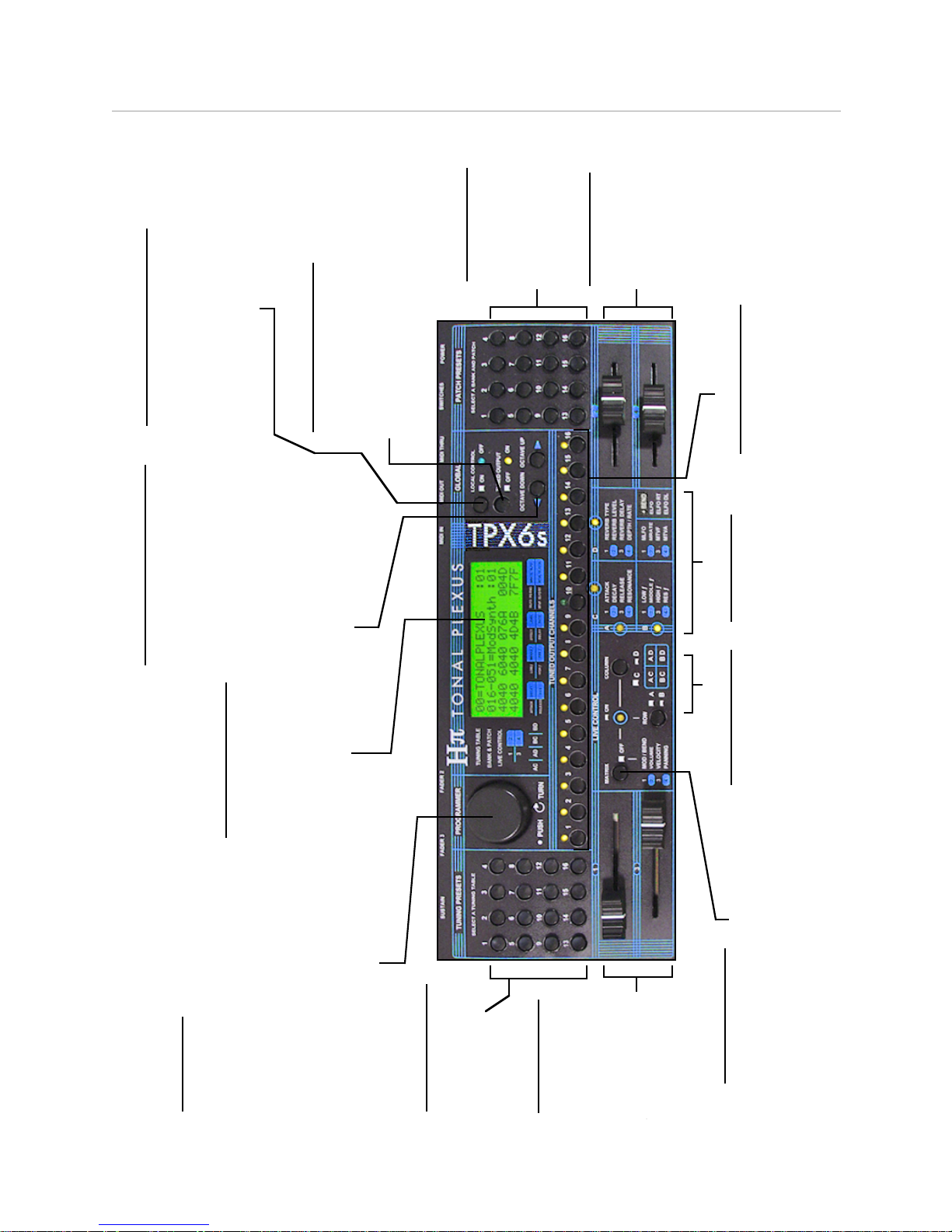
16 Tuning Presets
Press these buttons
to recall a preset
tuning tables.
16 Patch Presets
Press these
buttons to recall
preset banks and
patches.
LOCAL CONTROL Switch
When Local Control is OFF, the blue
LED lights up, and only MIDI
received at MIDI IN travels to the
internal synthesizer, which can be
useful when working with
sequencing and notation software.
4 x 20 Character LCD
Displays the currently
selected preset tuning
table, bank, patch,
preset numbers, and
Live Control global
hexadecimal values .
Octave Up / Down Switches
Navigates the currently selected
tuning table by table octaves.
NOTE: In the default Master
Tuning, this corresponds to
transposition by octaves;
however, the pitches stored in
user tables may correspond to
anything, so shifting by table
octaves does not necessarily
require shifting by octaves in
terms of pitch.
TUNED OUTPUT Switch
ON: multi-channel pitch bend output,
for use with the internal synthesizer or
external MIDI gear; OFF: untuned raw
MIDI notes output, for use with external
retuning gear such as software
samplers and synthesizers.
16 Channel Switches
Use these switches to control
polyphony – which channels receive
tuned MIDI output.
NOTE: Channel 10 is MIDI
percussion
Faders 2 and 4
Fader 2 nromally
sends Key Velocity,
and fader 4 sends
MIDI Panning. In the
Live Control Matrix,
these faders send
various messages.
MATRIX ON / OFF
An LED shows the state of this switch
- OFF: the functions of the four faders
are 1 - Modulation, 2 - Velocity, 3-
Volume, 4 - Panning. ON: fader
functions are determined by the ROW
and COLUMN switches.
Overhead Diagram
ROW and COLUMN
Use these switches
to select from four
groups of Live
Control parameters.
MATRIX LEDs
These LEDs show
which ROW and
COLUMN of the Live
Control Matrix is
selected.
!" INSTRUMENTS www.h-pi.com · T O N A L P L E X U S T P X 6s/8s · User Manual 4
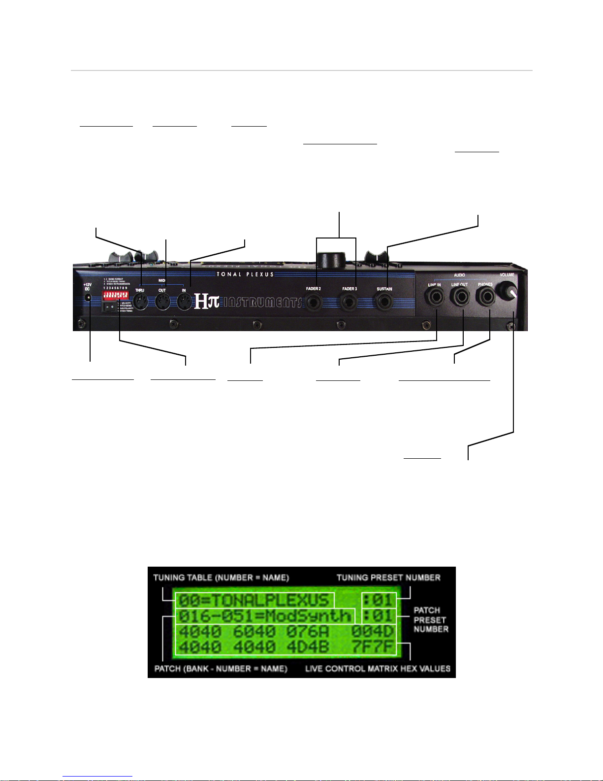
Back Panel Diagram
MIDI IN
Connect
another MIDI
controller to
this jack, also
used for
uploading
tuning tabels
to the
keyboard.
MIDI THRU
This output
sends MIDI
data received
at MIDI IN
through
unmodified to
another MIDI
device.
MIDI OUT
Connect a
synthesizer,
sampler or MIDI
interface to this
jack to receive
retuned or raw
MIDI data on
selected MIDI
channels.
12V DC Input
TPX6s/8s
require at least
2.5 Amps.
Power switch
provided.
LINE IN
Input a line level
audio signal from
any other source
directly to the
internal amplifier
using this 1/4”
jack. NOTE: This
input turns off
internal audio.
LINE OUT
Output line level
audio from the
internal amplifier
to an external
device suxh as
a mixer or
amplifier using
this 1/4” jack.
Stereo Headphones
Connecting headphones
to this attenuated stereo
output turns off speaker
output.
Volume
Control the amplifier output
to either the speakers or the
headphones with this knob.
SUSTAIN
Connect a
sustain (a.k.a.
Damper) pedal
to this 1/4” jack.
Volume Pedals
Connect Lo-Z (22 kOhm)
volume pedals to these 1/4”
jacks to control MIDI Volume
and Key Velocity (these inputs
override top panel faders)
DIP Switches
Control nine
parameters at
startup using
these DIP
switches (see
Appendix)
LCD Display
The 4 x 20 character backlit LCD normal display is shown below.
This display changes format in the following situations:
!" INSTRUMENTS www.h-pi.com · T O N A L P L E X U S T P X 6s/8s · User Manual 5
1. when Tuning Table data is being programmed
2. when all TUNED OUTPUT CHANNELS are switched OFF
3. when the TUNED OUTPUT switch is set to OFF
4. when GLOBAL PARAMETERS are resetting
2. Keyboard Layout
The Tonal Plexus keyboard geometry was designed in 2002 by Aaron Andrew Hunt. This particular
geometry is unique in the history of the musical keyboard, although it bears resemblance to previous
inventions known as generalized keyboards, early examples of which are found in the work of Paul
Von Janko (1875) and R.H.M. Bosanquet (1877).
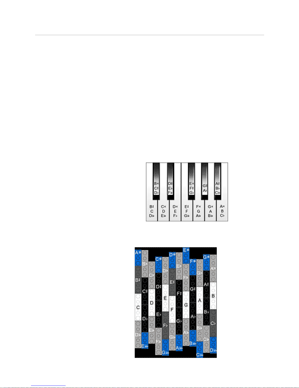
From Piano To Plexus
The Tonal Plexus keyboard layout is based on the traditional piano keyboard pattern of 7 white and
5 black keys, with standard fifths-based note names as shown below, piano keys carrying multiple
names as shown.
• 7 naturals
• 7 sharps
• 7 flats
• 7 double-sharps
• 7 double-flats
All standard note names correspond to unique, non-dulpicate keys on the Tonal Plexus. Extended
fifths-based note naming leads to a new set of enharmonics.
• 6 triple-sharps
• 6 triple-flats
!" INSTRUMENTS www.h-pi.com · T O N A L P L E X U S T P X 6s/8s · User Manual 6
These 12 new enharmonic keys are shown at the top and bottom edges of the layout, the blue keys
in the images above and Figure 1 below.
Figure 1
Default Master Tuning 205ET
The master tuning of the Tonal Plexus was determined by way of thorough research in music theory,
music notation, and pitch perception. The result is a system which allows the free exploration of all
possible pitch combinations in a coherent way, according to reasonable limits of human perception.
A few main concepts behind the master tuning are given below. Further information about the master
tuning will be made available in a separate document.
Octaves and fifths
Octaves and fifths define the basis of Western music theory and notation. Hence, these intervals
form the basis of the master tuning. Octaves are tuned purely, and fifths are tuned virtually purely,
with a deviation of less than half of one cent. These two intervals provide a reference for pitch
ordering and naming relative to which all other intervals are defined.
!" INSTRUMENTS www.h-pi.com · T O N A L P L E X U S T P X 6s/8s · User Manual 7
Commas and JNDs
The master tuning is designed around the comma as a basic interval. The comma used is just under
30 cents in size, forming the basis of a key layout in which one octave contains 41 commas. To
maximize pitch control and expressivity, each comma is broken into 5 JNDs, so that the smallest steps
on the keyboard are just under 6 cents in size. Each octave contains 205 JNDs. Using JND fine
tuning, any interval can be played with a maximum tuning deviation of less than 3 cents. Though
under certain conditions such small mistunings can be heard, in practice the errors are so small that
they are not noticeable; other natural variables such as timbre and duration introduce similar small
margins of error. The master tuning is thus contains all pitches and intervals in a managable way.
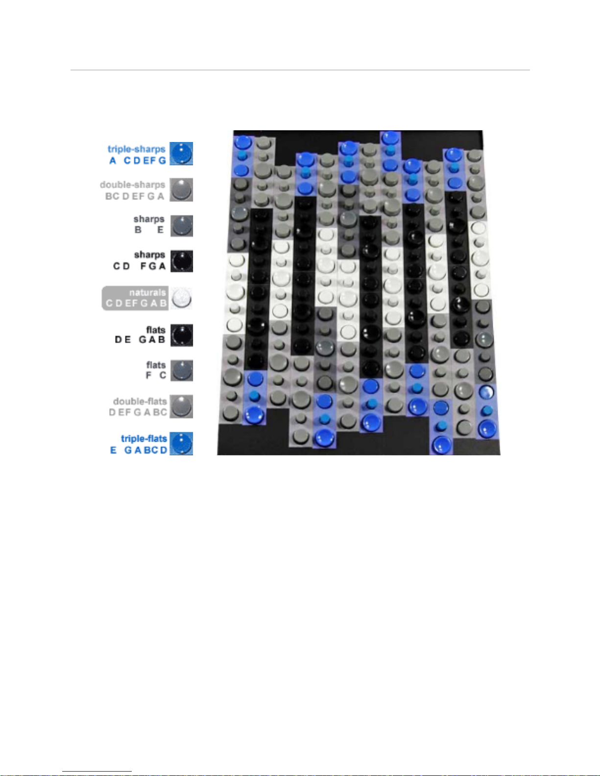
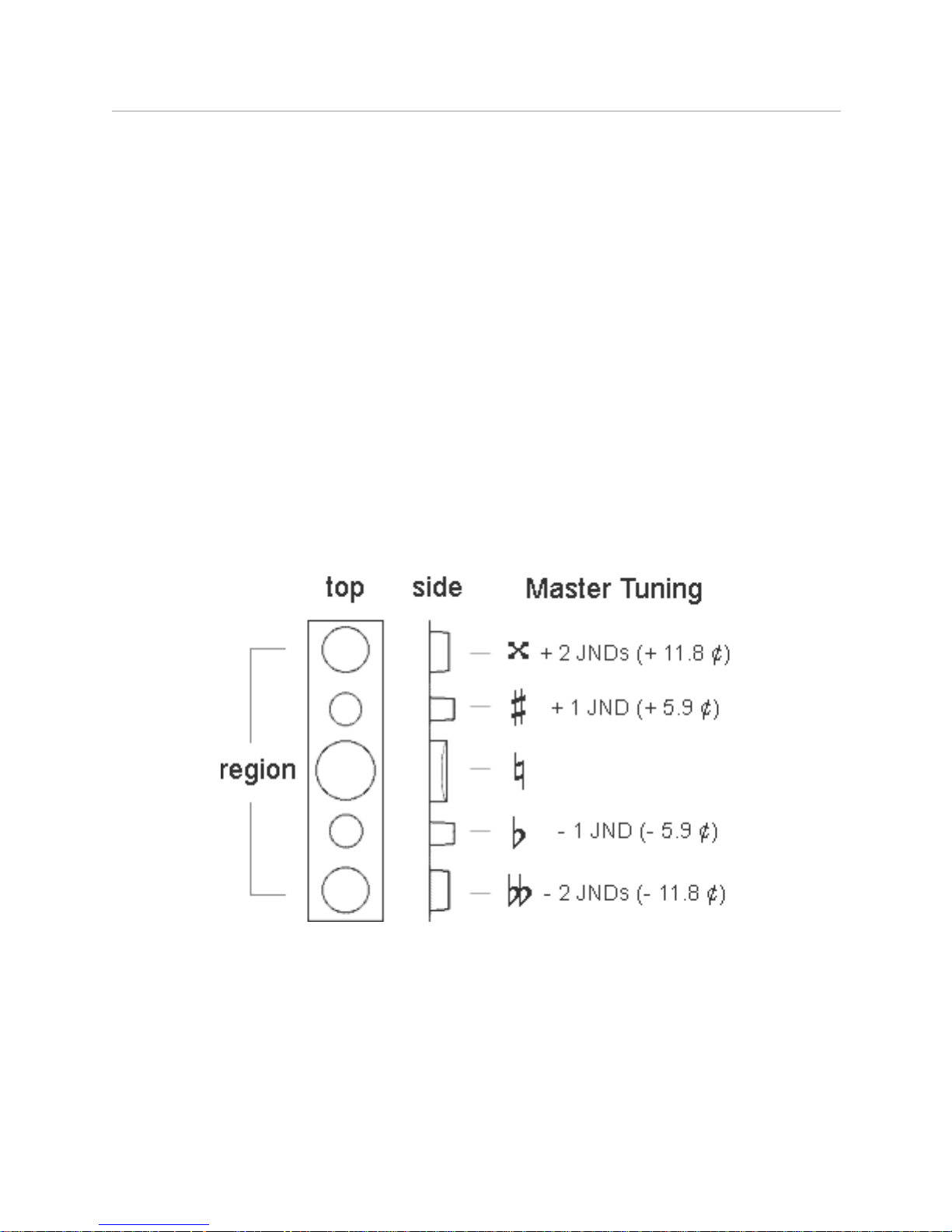
Key Diameter and Elevation
Tonal Plexus keytops vary in diameter and elevation, arranged symmetrically in 41 regions per
octave. The center key of each region has a concave surface and is the largest in diameter. The
other keys are smaller and have flat tops. These variations of diameter and elevation provide a tactile
terrain for navigation of the keyboard by touch. In the default Master Tuning, the variations
correspond to JND inflections of a given letter name, allowing harmonic intervals to be easily found by
touch alone.
!" INSTRUMENTS www.h-pi.com · T O N A L P L E X U S T P X 6s/8s · User Manual 8
3. Tuning Tables
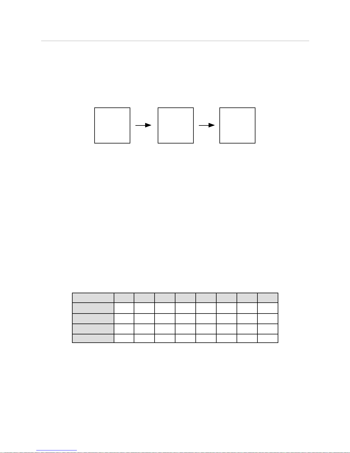
Each tuning table provides a simple 1 to 1 correspondence between raw MIDI Notes played and
retuned MIDI Notes output. Any MIDI Note input can be retuned to any pitch output, in any register
with any frequency, limited only by the internal or external synthesizer.
MIDI
Note
played
Tuning
Table
lookup
Tuned
MIDI
Note
OUT
There are 32 memory locations, numbered 0 - 31, available for storing tuning tables. There are 16
preprogrammed default tuning tables, including the Master Tuning 205ET. The default tuning tables
may be overwritten, and there are no protected memory locations. Each table is given a 16-character
name. The name and number of the currently selected tuning table is displayed on the top row of the
LCD. For each MIDI Note, there are three values stored in the tuning table: MIDI Note, Pitch Bend
MSB and Pitch Bend LSB. When a MIDI Note ON message is received, these values are looked up
and immediately transmitted to MIDI OUT in the following order: Pitch Bend MSB, Pitch Bend LSB,
MIDI Note ON.
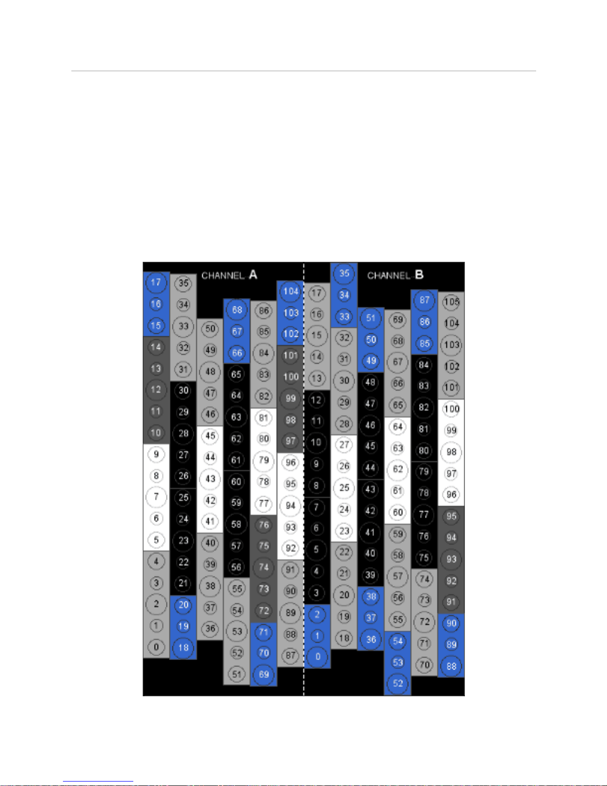
MIDI Mapping
Each octave of a Tonal Plexus keyboard uses two MIDI Channels, each assigned to six columns of
keys. These two MIDI Channels are shown as CHANNEL A and CHANNEL B in Figure 2 (next page).
The MIDI Note numbers are the same in each octave, and the MIDI Channels are fixed according to
the size of the keyboard. The chart below shows MIDI Channel assignments for TPX6s and TPX8s.
These MIDI Notes and Channels should be sent from external devices connected to MIDI IN.
OCTAVE
CHANNEL A
CHANNEL B
TPX8s
TPX6s
1234567813579111315246810121416XXXXXXXXXXXXX
X
MIDI Notes 0-104 are used from Channel A and MIDI Notes 0-105 are used from Channel B. This
leaves 22 MIDI Notes (105-127) unused on Channel A and 21 MIDI Notes (106-127) unused on
Channel B. These 43 unused MIDI Notes correspond to 43 unused Tuning Table Registers for each
Tonal Plexus octave. Although these free memory registers are ignored by the keys of a Tonal
Plexus keyboard, they may be accessed from an external keyboard by sending the correct MIDI
Notes on the correct MIDI Channels to MIDI IN.
!" INSTRUMENTS www.h-pi.com · T O N A L P L E X U S T P X 6s/8s · User Manual 9
Untuned Output Mode
The Tonal Plexus keyboard normally sends tuned output corresponding to MIDI Note and Pitch Bend
data stored in a Tuning Table; however, when the top panel TUNED OUTPUT switch is set to OFF,
the raw MIDI Note and Channel data shown above is sent to MIDI OUT. This data can then be
received by an external processor such as a software sampler to result in retuned output.
Duplicate Keys
In the default Master Tuning, the following pairs of keys are tuned to the same pitch: Channel A 17 &
18, 68 & 69, 104 & Channel B 0. Channel B 35 & 36, 51 & 52, 87 & 88. These are the keys referred
to as duplicate keys in TPXE software, the large blue keys in Figure 2 below. These keys are not
hard-wired as duplicates; custom user tunings can have any key mapped to any pitch.
Figure 2
!" INSTRUMENTS www.h-pi.com · T O N A L P L E X U S T P X 6s/8s · User Manual 10

Programming a Tuning Table
Programming a tuning table means storing it in one of the 32 possible memory locations. Tables are
programmed using Tonal Plexus Editor (TPXE) software. Please see the software documentation for
information on creating and programming tuning tables.
NOTE: When sending tuning tables to TPX6s/8s keyboards, first set all the faders
to zero (the leftmost position). This will help ensure that data is received for
every key of the tuning table, a known issue for these keyboards. If some keys
still do not get programmed, the table should be sent again.
Local Control Switch
The switch called LOCAL CONTROL on TPX6s/8s provides a way to disconnect MIDI traffic coming
from the keyboard. This setting should be used when you wish to control the synthesizer from an
external source such as a sequencer. When LOCAL CONTROL is set to OFF, the blue LED lights up
and the keyboard no longer generates MIDI data; however, incoming MIDI data is still sent to the
internal synthesizer. This function is unlike standard LOCAL OFF control, where MIDI data is still sent
from the keyboard. The reason for this is that MIDI channel control may possibly be in conflict if MIDI
data input and MIDI output are both allowed to directly control the internal synthesizer when
bypassing the internal dynamic channel allocation algorithm. MIDI output is however still sent to the
THRU output, so in a limited sense the function is as expected for a LOCAL OFF situation, with the
caveat that output can only be UNTUNED in this situation, and some functions become inactive in
this mode.
Octave Buttons
The octave buttons do not simply transpose MIDI Notes by octaves. Instead, they control which
tuning table registers are accessed by the MIDI Notes played. So, the word “octave” in this case
should be understood to mean a tuning table MIDI map octave as described above.
4. Polyphony
TPX6s/8s achieves microtonal polyphony through a MIDI channel assignment system, called a
dynamic channel allocation algorithm. Each retuned MIDI Note requires its own MIDI channel.
Therefore, polyphony is limited to 16 voices according to the present MIDI standard.
!" INSTRUMENTS www.h-pi.com · T O N A L P L E X U S T P X 6s/8s · User Manual 11

Octave 1
Octave 2
Octave 3
Octave 4
Tuned
MIDI
Notes
OUT
Channels 1, 2
Channels 3, 4
Channels 5, 6
Channels 7, 8
MIDI
Notes
played
Tuning
Table
lookup
Channel 1
Channel 2
Channel 3
Channel 4
Channel 5
Channel 6
Channel 7
Channel 8
Channel 9
Channel 10
Channel 11
Channel 12
Channel 13
Channel 14
Channel 15
Channel 16
Channels 9, 10
Channels 11, 12
Channels 13, 14
Channels 15, 16
Octave 5
Octave 6
Octave 7
Octave 8
TPX8s
TPX6s
Dynamic
Channel
Allocation
You control which channels receive retuned MIDI output with the 16 channel switches. For example,
if channels 3, 4, 5 and 6 are engaged and all other channels are disengaged, MIDI Notes will only be
sent on channels 3, 4, 5, and 6. Such control is particularly useful for sequencing multitimbral music.
Octave 4
Tuned
MIDI
Notes
OUT
Channels 7, 8
MIDI
Notes
played
Tuning
Table
lookup
Channel 4
Channel 5
Channel 6
Channel 3
Dynamic
Channel
Allocation
NOTE: MIDI channel 10 is reserved for percussion sounds on General MIDI
synthesizers. To remind you of this, the channel 10 LED is colored green rather
than yellow, and the number is underlined. If you hear a percussion sound every
few notes, then you need to disengage channel 10.
5. Presets
The TPX6s/8s has 16 table presets and 16 patch presets. Each table preset allows a tuning table to
be recalled at the touch of a button without affecting the current bank and patch. Each patch preset
consists of a bank and patch to be recalled at the touch of a button without affecting the current
tuning table. Additionally, the TPX6s/8s stores a total of twenty Global Parameters, so named
because these parameters affect the entire keyboard regardless of the selected patch or tuning
table; details on these parameters are in the section of the manual titled Live Control.
!" INSTRUMENTS www.h-pi.com · T O N A L P L E X U S T P X 6s/8s · User Manual 12

Pressing the knob initiates the preset programming or browsing process. Browse parameters by
turning the knob, and choose values by pressing the knob. While browsing a parameter, that
parameter flashes on the display.
Storing a Table Preset
To store a table preset, follow these steps:
(1) Push the PROGRAMMER knob. The table preset number and patch preset number flash.
(2) Push the table preset button you wish to program
(3) Turn the knob to find the desired tuning table.
(4) Select a tuning table by pressing the knob. The table preset is stored
Storing a Patch Preset
To store a patch preset, follow these steps:
(1) Push the PROGRAMMER knob. The table preset number and patch preset number flash.
(2) Push the patch preset button you wish to program.
(3) The bank number flashes.
(4) Turn the knob to find a desired bank.
(5) Select a bank by pressing the programmer knob. The patch number flashes.
(6) Turn the knob to find a desired patch.
(7) Select a patch by pressing the knob. The patch preset is stored.
!" INSTRUMENTS www.h-pi.com · T O N A L P L E X U S T P X 6s/8s · User Manual 13
The process above may be canceled at any moment by pressing any preset button. In this case the
display stops flashing and preset programming stops. Programming may be initiated again according
to the steps above.
NOTE: Bank Select messages are handled differently by different manufacturers.
TPX6s/8s includes DIP switches for selecting the correct format for your
synthesizer. Consult the Appendix for more information on Bank Select DIP
switch settings.
6. Live Control
TPX6s/8s keyboards allow control of twenty global parameters of the internal synthesizer, sixteen of
which are displayed on the LCD and are accessible at any time. The parameters are called global,
because they affect the sound of the synthesizer regardless of the selected patch. The parameters
are persistent until changed, are saved in memory and are recalled when the keyboard is turned on.
At any time, with the MATRIX switch set to OFF, the parameters may be reset by pressing and
holding the PROGRAMMER knob for four seconds. The display will read RESETTING GLOBAL
PARAMETERS.
NOTE: if a volume pedal is plugged in, it will override the fader (2 or 3), in which
case setting live control parameters will require using the pedal rather than the
fader. The same applies to the joystick option; if the joystick is ON, it must be
used to set the parameter normally controlled by fader 1.
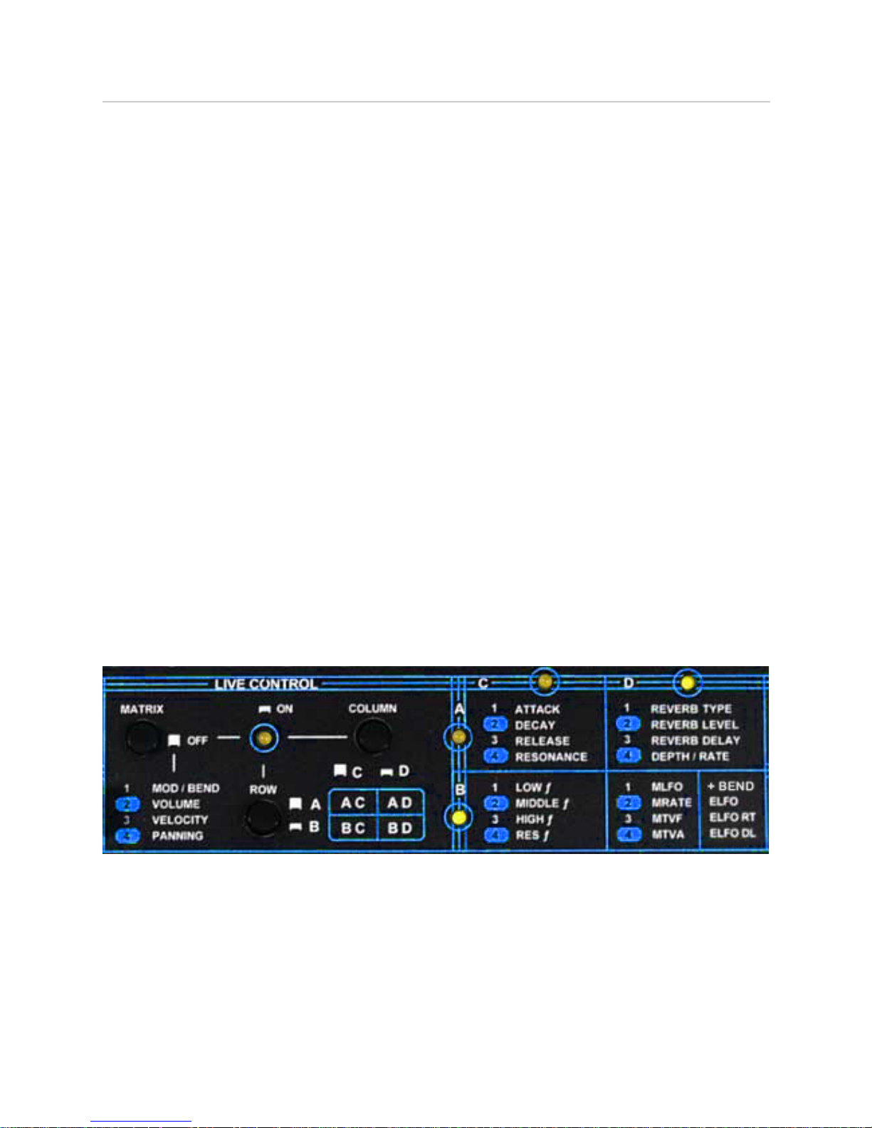
Switches and Control Groups
The parameters are organized together by similar function into four Groups, as shown on the top
panel. The ROW switch toggles between rows A and B, while the COLUMN switch toggles between
columns C and D. The LEDs on the matrix show which row and column is selected, and the LED on
the left shows when Live Control is ON, or OFF. The control groups are as follows.
!" INSTRUMENTS www.h-pi.com · T O N A L P L E X U S T P X 6s/8s · User Manual 14

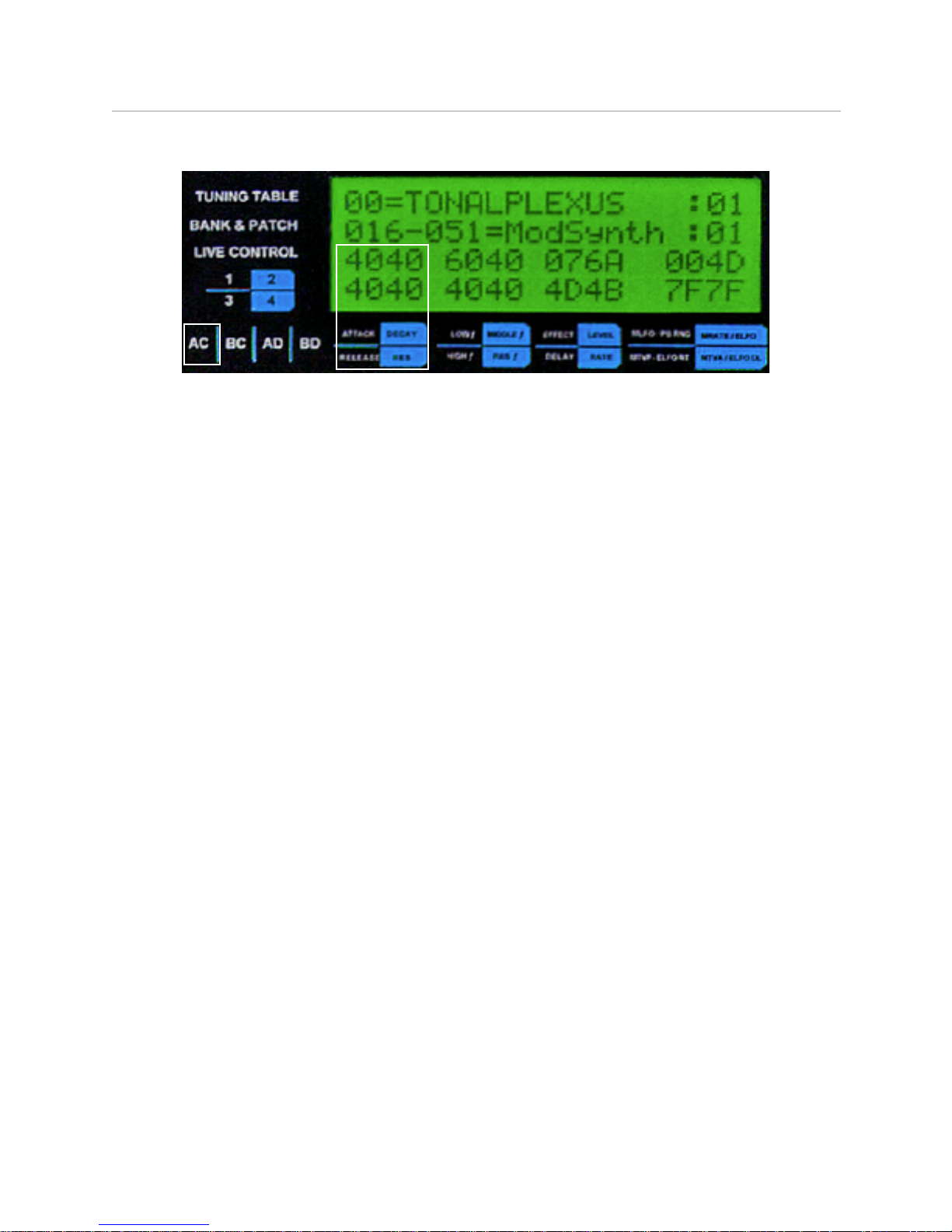
Hex Display
It is useful to be able to see the values of all Live Control parameters at once; therefore, these
values are all visible at once on the LCD display, with labels on the panel corresponding to the
parameter groups. Because the display space is limited, and because MIDI values are normally
expressed in hexadecimal (hex) notation, the display shows the values in hex rather than decimal
notation. For those unfamiliar with hex notation, the essential details as well as a lookup table are
given in the Appendix.
The graphic arrangement of fader numbers to the left of the display corresponds to four 2-digit hex
values in each group on the right, showing how the faders correspond with each parameter. For
example, correspondences for the Equalizer Group are shown below:
The meanings of these values are identified by the similar graphic arragement below the display, and
the two-letter code for the group is also shown to the left and below the display, matching up with the
Live Control Matrix.
!" INSTRUMENTS www.h-pi.com · T O N A L P L E X U S T P X 6s/8s · User Manual 15
Waveform Group (AC)
This group allows you to control in real time some basic aspects of how the amplitude and frequency
content of a patch changes over time, according to the ADSR (Attack, Decay, Sustain, Release)
waveform model. For these parameters, setting a fader position at center will give the factory default
value (40h) for each patch.
NOTE: The ADR portion of the Waveform Group can be used to control external
synthesizers which conform to the Roland GS standard; for example, the Edirol
SD-20.
Fader 1: ATTACK: NRPN 01h 63h Modify the attack or initial onset portion of the waveform. A
minimum value gives an immediate onset, increasing the percussiveness of a sound, useful for quick,
rhythmic playing. A maximum value gives the equivalent of a slow crescendo to every note, useful for
slower, more expressive playing.
Fader 2: DECAY: NRPN 01h 64h Modify the decay portion of the waveform. The decay directly
follows the attack, before the sustaining sound is reached. A minimum value allows the attack portion
to immediately proceed to the sustaining sound. A maximum value may add a slight swelling effect
immediately following the attack, or a slight decrescendo preceeding the sustaining sound, or a
combination of these effects.
Fader 3: RELEASE: NRPN 01h 66h Modify the release or final portion of the waveform. A minimum
value results in immediate cutoff of the sustaining sound once a key is lifted. A maximum value allows
the sustaining sound to continue, gradually reducing in loudness until it is finished.
NOTE: high release values may cause unwanted pitch bending effects from the
internal synthesizer or external Roland GS module.
Fader 4: RESONANCE: NRPN 01h 21h modify the harmonic content of a patch during its sustain by
varying the level of a TVF (Time Variant Filter). This resonance can be thought of as the maximum
amplitude of a band pass filter which changes over time, whose cutoff frequency is determined by
fader 4 of the Equalizer Group. A minimum value results in a static sustain, while a maximum value
results in dynamic alterations of harmonic content during the sustain.
!" INSTRUMENTS www.h-pi.com · T O N A L P L E X U S T P X 6s/8s · User Manual 16

Equalizer Group (BC)
The frequency content of sounds determine their quality of audibility across a wide range of pitches.
Generally speaking, human ears are most sensitive to midrange frequencies, and less sensitive to
high and low frequencies. For each of faders 1, 2 and 3, ± 0 dB is at center (40h), while a minimum
value (00h) gives a -12 dB cut, and a maximum value (7Fh) gives a +12 dB boost.
Fader 3: LOW ƒ: NRPN 37h 00h Modify the amplitudes of low frequencies (center ƒ 40 Hz). The
human ear tends to perceive lower frequencies as providing body and projection to sounds, so a
minimum value results in a thinner sound, while a maximum value results in a fuller (but possibly
distorted) sound. The factory default setting is 60h = +6 dB.
Fader 2: MIDDLE ƒ: NRPN 37h 01h, NRPN 37h 02h Modify the amplitudes of midrange frequencies
(center ƒ 1.8 kHz). The human ear is most sensitive to frequencies in the middle range, so a minimum
value results in a less audible, possibly muffled sound, while a maximum value results in a more
audible, but possible blaring sound.
Fader 1: HIGH ƒ: NRPN 37h 03h Modify the amplitudes of high frequencies (center ƒ 9.3 kHz).
Human ears tend to perceive higher frequencies as providing clarity to sounds, so a minimum value
results in a duller, less clear sound, while a maxium value results in a brighter, clearer (but possibly
glassy) sound. The factiory default setting is 60h = +6 dB
Fader 4: RES ƒ: NRPN 01h 20h Modify the cutoff frequency of the TVF (Time Variant Filter) whose
amplitude is controlled by fader 4 of the Waveform Group. This can be thought of as a band pass
filter which changes over time, according to the value of fader 4 of the Waveform group. The cutoff
frequency determines the nature of the dynamic alteration of the sustaining portion of the sound. A
minimum setting results in filtering of middle to high frequencies over time, whle a maximum setting
results in boosting middle to high frequencies over time. The factiory default setting is 40h = 2.2 kHz
!" INSTRUMENTS www.h-pi.com · T O N A L P L E X U S T P X 6s/8s · User Manual 17
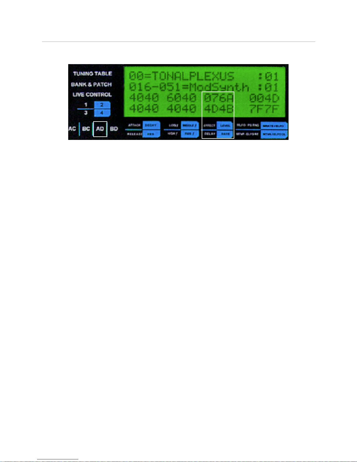
Effect Group (AD)
Effects can used to help electronically produced sounds come across to the listener as less artificial
and more realistic. The available options in the Effect Group are eight basic types of reverb (short for
reverberation) which mimic the acoustic phenomenon of sound wave reflections and absorbtions
generated by a source within a physical space such as a concert hall.
NOTE: some Effect Group values may respond slowly to changes in fader
positions. This is because system exclusive messages are being used. To see
values as they change, first move the fader or pedal, then wait to see the value
change on the LCD, and hear the change in output from the synthesizer.
Fader 1: REVERB TYPE: F0h 41h 00h 42h12h 40h 01h 30h VV xx F7h Eight types of sound
spaces are simulated by variations in the reverb effect, so that fader values range between 00 and
07. Each value corresponds to a type of space as follows:
00: ROOM 1 01: ROOM 2 02: ROOM 3 - mimics spaces with many early reflections
03: HALL 1 04: HALL 2 - mimics spaces with more late reflections than early reflections
05: PLATE - mimics the effect of a transducer placed on a metal plate within the space
06: ECHO - mimics repeated delayed refelctions, panned center
07: STEREO PAN ECHO - mimics repeated delayed reflections, panning back and forth
When a value of 06 or 07 is selected, fader 4 controls the rate of echo repetition; otherwise fader 4
controls the relative size of the space. The default factory setting is 04: HALL 2.
Fader 2: REVERB LEVEL: F0h 41h 00h 42h12h 40h 01h 33h VV xx F7h Control the presence of
the reverb in the ouput. A minimum value will eliminate the reverb effect (dry output), while a
maximum value will amplify the reverb effect (wet output). The factory default setting is 64h.
Fader 3: REVERB DELAY: F0h 41h 00h 42h12h 40h 01h 35h VV xx F7h Control the time between
the onset of the dry sound and the initiation of the reverb effect. A minimum value will cause the
reverb effect to begin immediately with the source, giving the impression of a smaller space, while a
maximum value will cause the effect to be audibly separated by a timing gap from the source, giving
the impression of a larger space. The factory default setting is 64h.
!" INSTRUMENTS www.h-pi.com · T O N A L P L E X U S T P X 6s/8s · User Manual 18
Fader 4: REVERB DEPTH / RATE: F0h 41h 00h 42h12h 40h 01h 34h VV xx F7h The function of
this control depends on the REVERB TYPE. If the TYPE is set to a value less than 06, then fader 4
will control the depth of the reflections, effectively altering the size of the space. A minimum value will
maximize early reflections making the space seem smaller, while a maximum value will amplify late
reflections making the space sound larger. If the TYPE is set to a value of 06 ot 07, fader 4 controls
the timing of echo repetitions. In this case a minimum setting results in very quickly repeating echos,
while a maximum setting results in very slowly repeating echos, also effectively altering the size of the
space. The factory default setting in all cases is 64h.
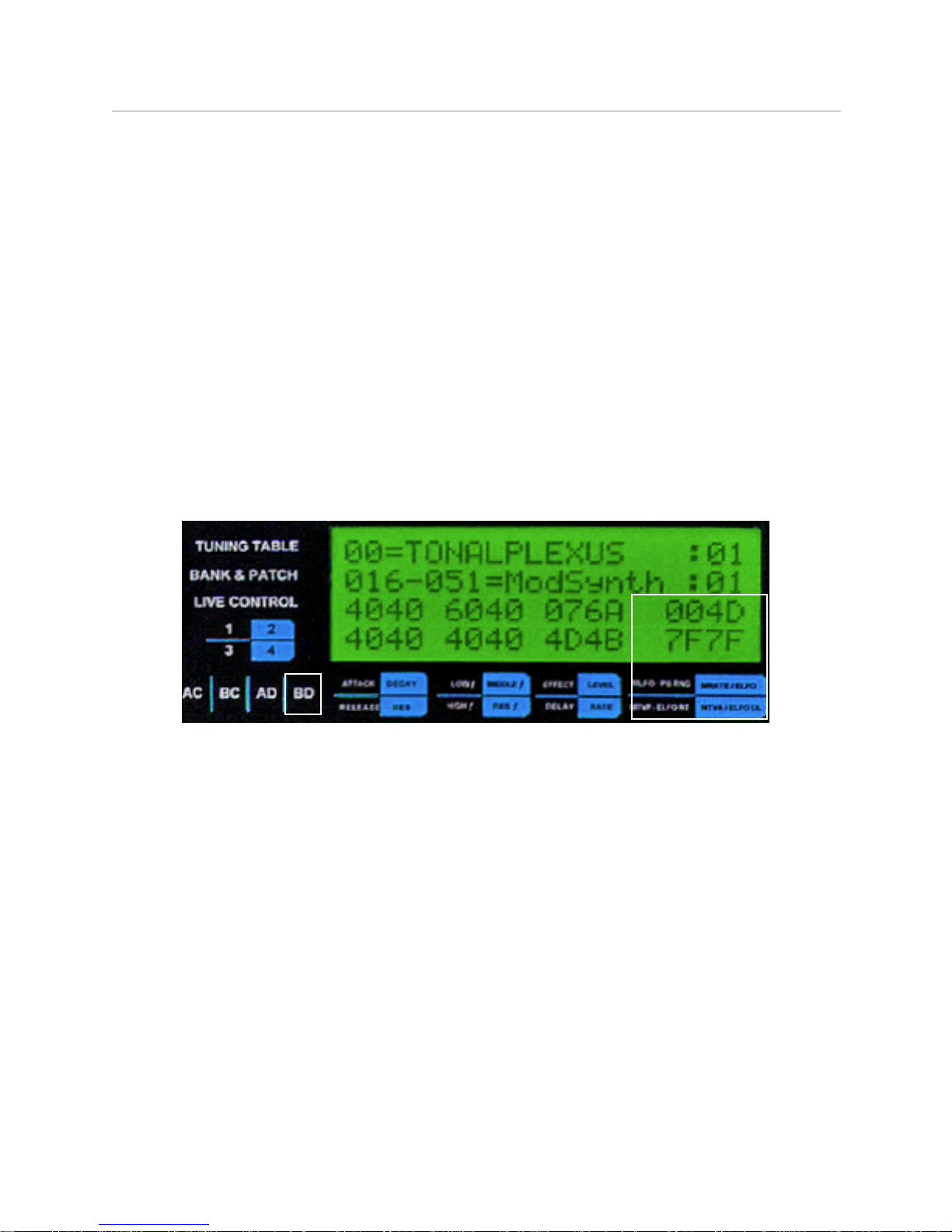
Modulation Group / Pitch Bend Group (BD)
The functions of faders in this group depend on the state of DIP switch 7, which determines whether
PITCH BEND MODE is ON or OFF. In either case, the modulation or pitch bend parameter itself is
controlled by fader 1 or the joystick when Live Control is OFF.
When DIP 7 is OFF, the faders function as follows:
Fader 1: MODULATION LFO DEPTH: F0h 41h 00h 42h 12h 40h 2nh 02h VV xx F7h Determine the
amplitude of a low frequency oscillator (LFO) applied to the source when the modulation parameter is
controlled. A minimum value results in reduction of overal amplitude output, while a maximum value
results in overall higher amplitude output. The factory default setting is 40h.
Fader 2: MODULATION RATE: F0h 41h 00h 42h 12h 40h 20h 03h VV xx F7h Determine the
frequency of the LFO applied to the source when the modulation parameter is controlled. A minimum
value results in high frequency oscillation, while a maximum value results in a lower frequency
oscillation. The factoy default setting is 40h.
NOTE: The LFO will not be heard if faders 3 and 4 are both in the zero position.
Fader 3: MODULATION TVF: F0h 41h 00h 42h 12h 40h 2nh 05h VV xx F7h Determine the
influence of the LFO on high frequency filtering over time during the sustain of the sound. A minimum
value means the LFO has no effect on high frequency content, while a maximum value means the
LFO causes pronouncd amplitude modulation of high frequency content, creating a noticeable
shimmering effect. The factory default value is 00h.
!" INSTRUMENTS www.h-pi.com · T O N A L P L E X U S T P X 6s/8s · User Manual 19
Fader 4: MODULATION TVA: F0h 41h 00h 42h 12h 40h 2nh 06h VV xx F7h Determine the
influence of the LFO on amplitude filtering over time during the sustain of the sound. A minimum
value means the LFO has no effect on amplitude, while a maximum value means the LFO causes
pronouncd amplitude modulation, creating a noticeable tremolo effect. The factory default value is
00h.
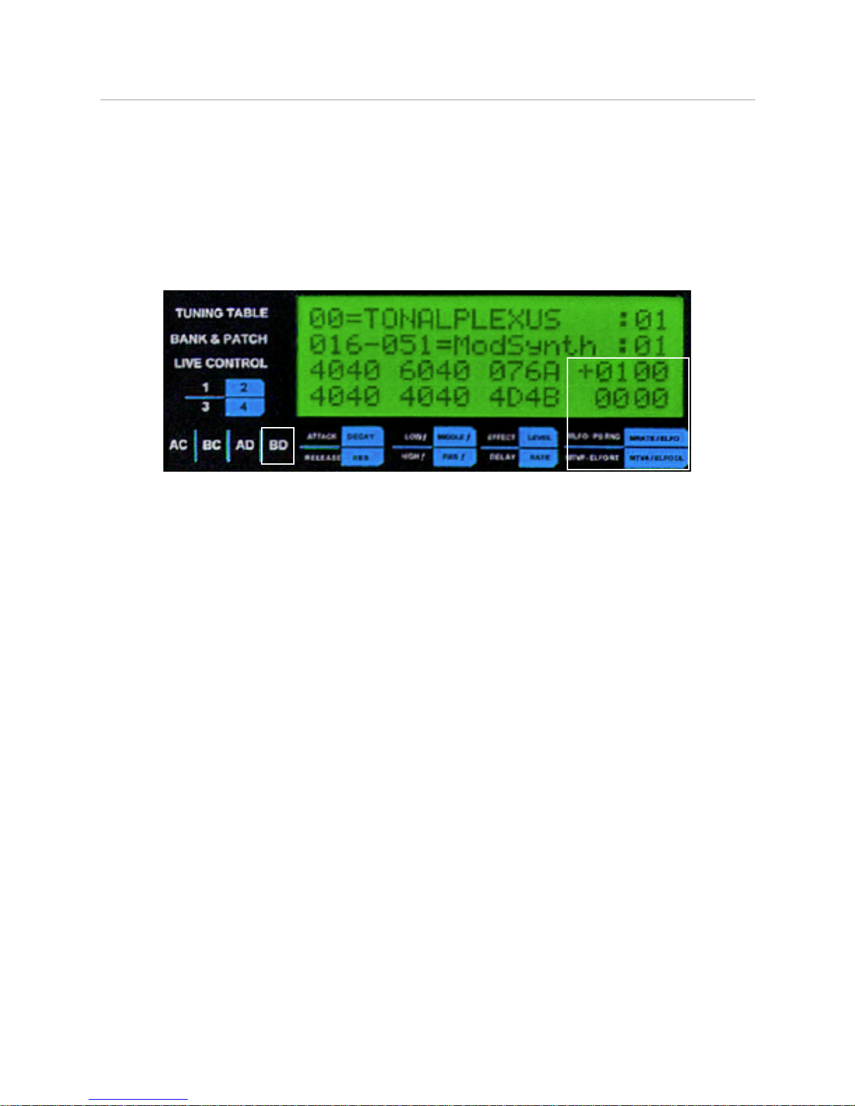
When DIP 7 is ON, the display contains the + character, and the faders function as follows:
Fader 1: + BEND: sets the pitch bend range in 12ET semitones. This is a pitch bending effect which
controls the global pitch through the modulation parameter, achived by the following series of
messages where VV is the value of fader 1:
F0h 41h 00h 42h 12h 40h 00h 05h (40h-VV) xx F7h - master key shift
F0h 41h 00h 42h 12h 40h 2nh 00h 40h+(2*VV) xx F7h - modulation pitch control
F0h 41h 00h 42h 12h 40h 2nh 04h 00h xx F7h - modulation pitch depth
The factoy default setting is +00.
NOTE: Because this method gives only 1 byte pitch bending precision, beyond a
bend range of ± 01, the bending may not occur smoothly.
Fader 2: ELFO LEVEL: NRPN 01h 09h Determine the level of a frequency modulation (vibrato) LFO
applied to the source during the sustain portion of the waveform. A minimum value results in no
modulation, while a maximum value results in very pronounced modulation, producing a vibrato
effect. The factoy default setting is 00h.
Fader 3: ELFO RATE: NRPN 01h 08h Determine the frequency of the vibrato LFO applied to the
source during the sustain portion of the sound. A minimum value results in a slow vibrato, while a
maximum value results in a very fast vibrato, or a pitch fluttering effect. The factory default value is
00h.
NOTE: the state of fader 3 will have no effect on the sound unless fader 2 (ELFO)
has a value higher than 00h.
!" INSTRUMENTS www.h-pi.com · T O N A L P L E X U S T P X 6s/8s · User Manual 20

Fader 4: ELFO DELAY: NRPN 01h 0Ah Determine the onset time of the vibrato LFO determined by
faders 2 (ELFO) and 3 (ELFO RATE) of this group. A minimum value means the LFO occurs
immediately at the initiation of the sustain portion of the sound, while a maximum value means the
vibrato is significantly delayed. This can be used to create vibrato or slow pitch changing effects only
on sounds which of longer duration, while sounds of short duration are not influenced at all by the
vibrato.The factory default value is 00h.
NOTE: the state of fader 4 will have no effect on the sound unless ELFO has a
value higher than 00h.
7. Joystick Option
The joystick is useful for controlling global pitch bending when the keyboard is in pitch bend mode
(DIP 7 ON). A switch is used to toggle between the joystick and fader 1. The joystick cannot be used
along with the fader at the same time; the toggle switch selects one control or the other. The main
advantage of the joystick over the fader is its spring-to-center return mechanism. Although the
joystick can be moved in all directions, it only controls the parameter assigned to fader 1. Its range of
motion is slightly more limited than that of the fader, so the maximum bending allowed with the
joystick will be slightly less than the indicated bend range.
NOTE: when changing Live Control parameters, be aware of the state of the
toggle switch. If the joystick is selected, it will be the control used to set Live
Control parameter values, which may be awkward because of its spring-to-
center return mechanism.
!" INSTRUMENTS www.h-pi.com · T O N A L P L E X U S T P X 6s/8s · User Manual 21

8. External MIDI Devices
This section gives some basic information about using external MIDI controllers and tone modules
with TPX6s/8s. Information on working with a sequencer will be made available in a separate
document.
Controllers
All MIDI controllers connected to MIDI IN will be compatible with TPX6s/8s, including keyboard
controllers, ribbon controllers, breath controllers, wind controllers, MIDI guitars, etc.
Standard Synthesizers and Samplers
Synthesizers and samplers connected to MIDI OUT should be MULTITIMBRAL. Check the MIDI
Implementation Chart of any unit you will be connecting. The following parameters must be there:
YOUR SYNTHESIZER’S MIDI IMPLEMENTATION CHART
FUNCTION
TRANSMITTED
RECOGNIZED
REMARKS
Pitch Bend
(X or O)
O
Channels 1-16
Control Change
(X or O)
O
Data Entry MSB
6
100, 101
(X or O)
O
RPN MSB, LSB
MODE 1: OMNI ON, POLY X = No O = Yes
There may be some menu settings on the external unit which you will need to configure to satisfy the
requirements outlined above.
NOTE: If MIDI Pitch Bend messages are not recognized, the external device
connected to MIDI OUT with TUNED OUTPUT switched ON will not be retuned!
Natively Microtonal Synthesizers and Samplers
Hardware or software synthesizers and samplers which already have native microtonal support can
be controlled by TPX6s/8s using either MIDI THRU or MIDI OUT with TUNED OUTPUT switched to
OFF. In each case, TPX6s/8s will send standard MIDI Note messages and the retuning will take
place in the external unit.
!" INSTRUMENTS www.h-pi.com · T O N A L P L E X U S T P X 6s/8s · User Manual 22

Startup Sequence
The following startup sequence should always be used with TPX6s/8s and anything connected to it:
1. Turn on any external units connected to MIDI OUT or MIDI THRU
2. Turn on TPX6s/8s
3. Turn on any external controller connected to MIDI IN
NOTE: TPX6s/8s will do nothing in response to an Active Sensing external
controller if the controller is turned on before TPX6s/8s.
8. Sequencer / MIDI Footswitch Control
TPX6s/8s can receive MIDI instructions remotely from many kinds of controllers, including
sequencers, notation programs and MIDI footswitches. In addition to NOTE ON and NOTE OFF
messages, TPX6s/8s responds to other MIDI messages which can be used to control the currently
selected bank, patch, and tuning table independent of TPX6s/8s physical controls. This way, MIDI
sequences and live performances can employ a number of different patches and tunings without
ever having to touch the controls on TPX6s/8s. For this reason we will refer to such control as
Remote (not to be confused with wireless control).
Patch Changes
TPX6s/8s responds to remote messages received on any channel. One simple message recognized
is Patch Change, which is Status byte 192-208 for channels 1-16. The Status byte should be
followed by one Data byte. The MIDI message format for this message is shown below.
Patch Change on Channel (192 - 208 = 1 - 16), Patch (0-127)
Bank Select
TPX6s/8s responds to several MIDI Continuous Controller (CC) messages. Controller messages are
MIDI Status bytes 176-190 for channels 1-16. The Status byte should be followed by a Controller ID
byte and then a Data byte. Bank Select MSB and LSB messages are both recognized.
Controller on Channel (176 - 190 = 1 - 16), Bank Select MSB, LSB (0, 32), Bank (0-127)
TPX6s/8s must be configured to send Bank Select messages in the format recognized by your
synthesizer, and this format is used by TPX6s/8s for both sending and receiving Bank Select
messages. For more information, see the Appendix: Bank Select DIP Switch.
!" INSTRUMENTS www.h-pi.com · T O N A L P L E X U S T P X 6s/8s · User Manual 23

Tuning Table Changes
Other controller messages allow remote selection of TPX6s/8s tuning tables. Three messages are
available which differ in the way that held notes are handled. These are Undefined Controllers,
numbers 116-118 (formerly 80-82). A Controller Status byte is followed by an ID byte and Data byte.
Controller on Channel (176 - 190 = 1 - 16), Controller ID (116-118), Tuning Table (0-127)
If notes are sustaining in one tuning and you want them to remain sounding in that tuning even after
the tuning table has been changed, use Controller ID number 116. If instead you want held notes to
change immediately to a new tuning, you have two options. The first is Controller ID number 117 in
which notes currently sounding are restruck with pitches in the new tuning. Controller ID number 118
shifts (bends) currently held notes to new pitches without restriking, but the changes in pitch for each
note are limited within the range of a 12ET halfstep.
!" INSTRUMENTS www.h-pi.com · T O N A L P L E X U S T P X 6s/8s · User Manual 24

9. DIP Switches
987654321
BANK
FORMAT
SYSEX
ON / OFF
BEND /
MOD
VELOCITY
BANDWIDTH
BEND
TIMING
SYSEX
TIMING
SUSTAIN
POLARITY
DIPs 1 & 2: Bank Select Format
According to the MIDI Specification, manufacturers may use Bank Select messages CC0 or CC32, or
both. TPX6s/8s sends Bank Select messages to MIDI OUT, and also recognizes Bank Select
messages received at MIDI IN. If you find that bank switching is not being handled correctly, the
TPX6s/8s DIP switches should be adjusted. Only switches 1 and 2 are used for the Bank Select
message. With only 4 possible combinations, trial and error may be faster than digging for information
in your synthesizer manual.
Default: Bank Select CC0
Option: Bank Select CC32
Option: Bank Select CC0, CC32
Option: Bank Select CC32, CC0
1 OFF : One byte message
2 OFF : Message is CC0
1 OFF : One byte message
2 ON : Message is CC32
1 ON : Two byte message
2 OFF : Message is CC0, CC32
1 ON : Two byte message
2 ON : Message is CC32, CC0
12432121212
1
To change the bank select format, turn the unit OFF, change the position of DIP switches 1 and 2,
and turn the unit back ON.
!" INSTRUMENTS www.h-pi.com · T O N A L P L E X U S T P X 6s/8s · User Manual 25
DIP 3: Pitch Bend Response Timing
Synthesizers from various manufacturers respond differently to Pitch Bend messages in terms of
timing. In order to produce pitches always sounding properly tuned, such that the Pitch Bend is not
audible after a note has begun sounding, TPX6s/8s sends MIDI Pitch Bend messages before MIDI
Note messages with a default timing gap of less than 5 milliseconds between the two messages. This
gap is well below the average perceptual threshold (some sources place this threshold as high as 35
ms). In some cases, a synthesizer or sequencer might quantize the timings of incoming MIDI data
such that the default gap is not enough, and a pitch may bend audibly after it is sounding, even
though the Pitch Bend message was sent in advance of the Note message. In this case, the Pitch
Bend Response Timing DIP switch should be adjusted. Switch 3 is used for this purpose. Timing may
be adjusted from the default of less than 5 ms to 15 ms, as shown below.
ON
Default: 0 ms
Option: ~ 10 ms
3 OFF : 0 ms
3 ON : ~10 ms
123
3
To change the pitch bend response timing, turn the unit OFF, change the position of DIP
switch 3, and turn the unit back ON.
DIP 4: Sysex Retransmission
By default, TPX6s/8s ignores all sysex messages which are not table programming messages;
however, you may want TPX6s/8s to retransmit other sysex messages which it receives. Switch 4 is
used for this purpose. A 120 ms recovery timing gap is controlled by DIP switch 9, for compatibility
with older equipment. To change the sysex retransmission function, turn the unit OFF, change the
position of DIP switch 4, and turn the unit back ON. NOTE: Switching DIP 4 ON may cause tuning
errors! Always turn 4 OFF before sending tuning tables.
Default: Sysex Retransmit OFF
Option: Sysex Retransmit ON
4 OFF : Sysex is not retransmitted
4 ON : Sysex is retransmitted
1
2
ON
442
!" INSTRUMENTS www.h-pi.com · T O N A L P L E X U S T P X 6s/8s · User Manual 26

DIPs 5 & 6: Velocity Randomization Bandwidth
The keys of TPX6s/8s are not velocity sensing, which means that the MIDI NOTE messages will be
sent from the unit with a constant velocity value. In some situations, constant velocity is preferable,
such as when controlling organ or harpsichord sounds; however, many patches will sound more
natural with some variation in the output velocities. To achieve more natural sounding output without
velocity sensing keys, a velocity randomization function may be used. DIP switches 5 and 6 control
the bandwidth of this randomization, from ± 0 to ± 15.
Default: Velocity Bandwidth = 0
Option: Velocity Bandwidth = 10
5 OFF : ± 0
6 OFF : ± 0
5 OFF : ± 0
6 ON : ± 5
5 ON : ± 10
6 OFF : ± 0
5 ON : ± 10
6 ON : ± 5
12436565656
5
Default: Velocity Bandwidth = 20
Default: Velocity Bandwidth = 30
The velocity fader or pedal control is used to vary the overall velocity output. When either DIP
switches 5 or 6 are ON, the velocity fader value serves as the center of a randomized velocity band.
For example, if the velocity fader is located around the value 80, and setting 2 above is used (where
DIP switch 6 is ON), the velocity values in the output will vary randomly between 75 and 85. To
change the velocity randomization settings, turn the unit OFF, change the positions of DIP switches 5
and 6 to the desired function, and turn the unit back ON.
DIP 7: Global Pitch Bend Mode
Because the Tonal Plexus uses MIDI Pitch Bend to retune pitches, the conventional expectation of
Pitch Bend control is lost. However, the internal synthesizer allows global pitch to be altered using a
special MIDI Modulation Pitch mode, which is part of the Roland GS standard. Using a combination of
MIDI messages to initialize global transposition and Modulation parameters at startup, the
conventional Pitch Bend function can be imitated, in which the MOD Fader controls global pitch. In
this mode, the center position of the MOD fader gives unmodified pitch, the top position bends pitch
up a 12ET wholestep, and the bottom position bends the pitch down a 12ET wholestep. To engage
!" INSTRUMENTS www.h-pi.com · T O N A L P L E X U S T P X 6s/8s · User Manual 27

this mode, turn the unit OFF and switch DIP switch 7 to the ON position, and then turn the unit back
ON.
Default: Pitch Bend Mode OFF
Option: Pitch Bend Mode ON
7 OFF : MOD Fader Controls Modulation
7 ON : MOD Fader Controls Global Pitch
12772
When DIP switch 7 is ON, the following MIDI sysex messages are sent to the internal synthesizer at
startup:
Global transposition set down one 12ET wholestep:
FOh 41 h 00h 42 h 12h 40 h 00h 05 h 3Eh 00h F7h
Modulation Pitch Range: (n = all channels)
FOh 41 h 00h 42 h 12h 40 h 2nh 00 h 44h 00 h F7h
Modulation LFO Amplitude set to Null: (n = all channels)
FOh 41 h 00h 42 h 12h 40 h 2nh 04 h 00h 00 h F7h
NOTE: DIP 7 ON will affect the internal synthesizer only, and may confuse
external MIDI gear unless that gear recognizes Roland GS sysex messages.
Because this method gives only 1 byte pitch bending precision, beyond a bend
range of ± 01, the bending may not occur smoothly.
DIP 8: Sustain Pedal Polarity
Sustain pedals are simple switches which may be either normally open (NO) or normally closed (NC).
If you find that your sustain pedal gives reversed results (notes sustain when the pedal is UP) then
turn the unit OFF, change the position of DIP switch 8, and turn the unit back ON.
Default: SUSTAIN POLARITY -
Option: SUSTAIN POLARITY +
8 OFF : Sus Pedal is an NO switch
8 ON : Sus Pedal is an NC switch
12882
!" INSTRUMENTS www.h-pi.com · T O N A L P L E X U S T P X 6s/8s · User Manual 28

DIP 9: Sysex Recovery Timing
When using DIP 4 ON to retransmit sysex data, you may need to use DIP switch 9 to add a
short delay to the retransmission, particularly if your unit is older.
Default: Sysex Recovery OFF
Option: Sysex Recovery ON
9 OFF : Sysex is retransmitted immediately
9 ON : Sysex retransmission is delayed 20ms
12992
!" INSTRUMENTS www.h-pi.com · T O N A L P L E X U S T P X 6s/8s · User Manual 29
APPENDIX
General MIDI Patch List
BANK 000
000 Grand Piano
001 Bright Piano
002 Electric Piano
003 Honkytonk Piano
004 Rhodes Piano
005 Cheezy Piano
006 Harpsichord
007 Clavichord
008 Celesta
009 Glockenspiel
010 Music Box
011 Vibraphone
012 Marimba
013 Xylophone
014 Tubular Bells
015 Dulcimer
016 Draw Organ
017 Percussive Organ
018 Rock Organ
019 Church Organ
020 Reed Organ
021 Accordion
022 Harmonica
023 Tango Accordian
024 Nylon Guitar
025 Steel Guitar
026 Jazz Guitar
027 Clean Guitar
028 Muted Guitar
029 Overdrve Guitar
030 Distorted Guitar
031 Harmonics
032 Acoustic Bass
033 Upright Bass
034 Picked Bass
035 Fretless Bass
036 Slap Bass
037 Bright Bass
038 Synth Bass
039 Synth Upright
040 Violin
041 Viola
042 Cello
043 Contrabass
044 Tremolo Strings
045 Pizzicato
046 Harp
047 Timpani
048 String Ensemble
049 Cheezy Ensemble
050 Synth Strings
051 Mod Synth
052 Choir Aahs
053 Voice Doos
054 Synth Voice
055 Orchestral Hit
056 Trumpet
057 Trombone
058 Tuba
059 Harmon Trumpet
060 Horn
061 Synth Trumpet
062 Mod Brass 1
063 Mod Brass 2
064 Soprano Sax
065 Alto Sax
066 Tenor Sax
067 Baritone Sax
068 Oboe
069 English Horn
070 Bassoon
071 Clarinet
072 Piccolo
073 Flute
074 Recorder
075 Chiff Flute
076 Glass Flute
077 Cheezy Flute
078 Whistle
079 Blockflöte
080 Square Lead
081 Saw Lead
082 Calliope
083 Bendup Lead
084 Electric Lead
085 Voice Lead
086 Mod Fifths
087 Fat Lead
088 Vibe Pad
089 Warm Pad
090 Polysynth Pad
091 Choir Pad
092 Glassy Pad
093 Steel Wool
094 Partial Sweep
095 Sweeping Pad
096 Synth Rain FX
097 Synth Fifths
098 Synth Chimes
099 Plucky Synth
100 Bright Aahs
101 Synth Goblin
102 Oi
103 Harsh Synth
104 Bendup Sitar
105 Banjo
106 Shamisen
107 Koto
108 Kalimba
109 Bagpipe
110 Fiddle
111 Regal
112 Bells
113 Agogo
114 Twangy Tines
115 Woodblock
116 Taiko Drum
117 Melodic Tom
118 Synth Drum
119 Reverse Cymbal
120 Guitar Fret Noise
121 Bad Breath
122 Seashore
123 Tweety Bird
124 Telephone
125 Helicopter
126 Applause
127 Gunshot
!" INSTRUMENTS www.h-pi.com · T O N A L P L E X U S T P X 6s/8s · User Manual 30

General MIDI Patch List
BANK 127
000 GrandPiano
001 BrightPiano1
002 BrightPiano2
003 ElectricPno1
004 ElectricPno2
005 ElecTines1
006 ElecTines2
007 HonkeyTonk
008 FlutterOrgan
009 DrawbarOrgan
010 TonewheelOrg
011 ChorusOrgan
012 FullOrgan1
013 FullOrgan2
014 FullOrgan3
015 Accordian
016 Harpsichord1
017 Hrapsichord2
018 Hrapsichord3
019 Clavichord1
020 Clavichord2
021 Clavichord3
022 Celesta1
023 Celesta2
024 SynthBrass
025 SlowBrass
026 SynthBrass2
027 SlowBrass2
028 SynBass1
029 SynthBass1
030 SynBass2
031 SynthBass2
032 CheezElectrc
033 HurdyGurdy
034 SynthAHHs
035 BowedGlass
036 ModFifths
037 PluckySynth
038 SynthChimes
039 Bagpipes
040 Bells
041 RainFX
042 Oboe
043 ChiffFlute
044 Sawtooth
045 HarshSynth
046 TubularBells
047 SquareWave
048 SynthStrings
049 TremoloStrng
050 SlowStrings
051 Pizzicato
052 Violin
053 Viola
054 Cello1
055 Cello2
056 Contrabass
057 Harp1
058 Harp2
059 NyolonGuitar
060 SteelString
061 CleanGuitar
062 FunkyGuitar
063 BendUpSitar
064 AcousticBass
065 UprightBass
066 PluckedBass
067 Fretless1
068 SlapBass1
069 SlapBass2
070 Fretless2
071 Fretless3
072 Flute1
073 Flute2
074 Piccolo1
075 Piccolo2
076 Recorder
077 PanFlute
078 SopranoSax
079 AltoSax
080 TenorSax
081 BaritoneSax
082 Clarinet1
083 Clarinet2
084 Oboe
085 EnglishHorn
086 Bassoon
087 Harmonica
088 Trumpet
089 HarmonTrmpt
090 Trombone1
091 Trombone2
092 Horn1
093 Horn2
094 Tuba
095 ModBrass1
096 ModBrass2
097 Vibes1
098 Vibes2
099 Kalimba
100 OrchBells
101 Glockenspiel
102 TubularBells
103 Xylophone
104 Marimba
105 Koto
106 TaishoKoto
107 Shakuhachi
108 Whistle1
109 Whistle2
110 Bottles
111 WeakFlute
112 Timpani
113 TomToms
114 BassDrum
115 SynthTom1
116 SynthTom2
117 TaikoDrum1
118 TaikoDrum2
119 ReversCymbal
120 BrakeDrum1
121 BrakeDrum2
122 OrchHit
123 Telephone
124 Birdy
125 Helicopter
126 Shimmering
127 UselessRain
!" INSTRUMENTS www.h-pi.com · T O N A L P L E X U S T P X 6s/8s · User Manual 31
Hexadecimal Values
In a base 16, or hexadecimal (hex) numbering system, there are 16 values per place: 0, 1, 2, 3, 4, 5,
6, 7, 8, 9, A, B, C, D, E, and F. As long as only a single digit (character) is present, there is no
ambiguity as to the value of the number, but confusion may result for numbers greater than 16 (F in
hex) because placeholders in hex stand for multiples of 16 rather than multiples of 10. To distinguish
base ten (normal) numbers from multi-place hex numbers, the letter h is sometimes used following the
number. For example, the number 40h = 64. The following chart shows a list of decimal values with
the corresponding hex values. The trailing h is omitted ifrom the hex values n this chart.
D e c . H E X D e c . H E X D e c . H E X D e c . H E X
0 00 32 20 64 40 96 60
1 01 33 21 65 41 97 61
2 02 34 22 66 42 98 62
3 03 35 23 67 43 99 63
4 04 36 24 68 44 100 64
5 05 37 25 69 45 101 65
6 06 38 26 70 46 102 66
7 07 39 27 71 47 103 67
8 08 40 28 72 48 104 68
9 09 41 29 73 49 105 69
10 0A 42 2A 74 4A 106 6A
11 0B 43 2B 75 4B 107 6B
12 0C 44 2C 76 4C 108 6C
13 0D 45 2D 77 4D 109 6D
14 0E 46 2E 78 4E 110 6E
15 0F 47 2F 79 4F 111 6F
16 10 48 30 80 50 112 70
17 11 49 31 81 51 113 71
18 12 50 32 82 52 114 72
19 13 51 33 83 53 115 73
20 14 52 34 84 54 116 74
21 15 53 35 85 55 117 75
22 16 54 36 86 56 118 76
23 17 55 37 87 57 119 77
24 18 56 38 88 58 120 78
25 19 57 39 89 59 121 79
26 1A 58 3A 90 5A 122 7A
27 1B 59 3B 91 5B 123 7B
28 1C 60 3C 92 5C 124 7C
29 1D 61 3D 93 5D 125 7D
30 1E 62 3E 94 5E 126 7E
31 1F 63 3F 95 5F 127 7F
!" INSTRUMENTS www.h-pi.com · T O N A L P L E X U S T P X 6s/8s · User Manual 32

MIDI Implementation Chart
FUNCTION
TRANSMITTED
RECOGNIZED
REMARKS
Pitch Bend
O
X
Channels 1-16
14-bit
MSB, LSB
Control Change
Aux
O
See p. _
X = No O = Yes
X
Active Sensing
O
O
O
O
O
O
O
Bank Select MSB
Bank Select LSB
Data Entry MSB
Data Entry LSB
Sustain
RPN MSB, LSB
See 1 below
0
32
6
38
64
100, 101
0 - 115, 119-127
Velocity
O
O
Channels 1-16
Note OFF
O
O
Channels 1-16
Note ON
O
O
Channels 1-16
1. Effects of Received Messages: (Presets are not altered by these messages)
Bank Select: changes the bank.
Program Change: changes the patch.
Controller 116: changes the tuning table, held keys remain sounding old pitches
Controller 117: changes the tuning table, held keys restrike with new pitches
Controller 118: changes the tuning table, held keys bend into new pitches
NOTE: Pitch bending without restriking is limited to the range of a 12ET halfstep.
All other controller messages are retransmitted on all currently engaged channels.
2. Sysex retransmission is controlled by DIP switch 4, recovery timing by DIP switch 9.
Program Change
O
O
Channels 1-16
System Exclusive
O3O
2
See p. _
O1O1O1O1O
1
O
1
O
1
!" INSTRUMENTS www.h-pi.com · T O N A L P L E X U S T P X 6s/8s · User Manual 33

System Exclusive Messages
Programming a tuning table note (24 bytes)
F0 - SysEx start
00 - first ID
21 - second ID
7F - third ID
01 - Device ID
00 - Message ID
tt - tuning table number (0..127 / 00..7F)
ll - octave channel number* (0..16 / 00..0F)
kk - channel note number (0..127 / 00..7F)
nn - MIDI note (0..127 / 00..7F)
pp - Pitch Bend MSB (0..127 / 00..7F)
pp - Pitch Bend LSB (0..127 / 00..7F)
00 - not used
00 - not used
00 - not used
00 - not used
00 - not used
00 - not used
00 - not used
00 - not used
00 - not used
00 - not used
00 - not used
F7 - SysEx end
TPX6s/8s responds with Key Record Dump:
F0 - SysEx start
nn - Note number (0-127)
pp - Pitch Coarse value (0-127)
pp - Pitch Fine value (0-127)
00 - not used
F7 - SysEx end
Programming a tuning table name (24 bytes)
F0 - SysEx start
00 - first ID
21 - second ID
7F - third ID
01 - Device ID
01 - Message ID
tt - tuning table number (0..127 / 00..7F)
cc - name, character 1
cc - name, character 2
cc - name, character 3
cc - name, character 4
cc - name, character 5
cc - name, character 6
cc - name, character 7
cc - name, character 8
cc - name, character 9
cc - name, character 10
cc - name, character 11
cc - name, character 12
cc - name, character 13
cc - name, character 14
cc - name, character 15
cc - name, character 16
F7 - SysEx end
NOTE: characters must be in ASCII format.
* see MIDI channel and note number assignments per octave in Section 3: Tuning Tables
Between sending a table name and a tuning table note, there must be at least 100 ms pause. There
must be 50 ms pause between sending successive table notes.
!" INSTRUMENTS www.h-pi.com · T O N A L P L E X U S T P X 6s/8s · User Manual 34

Troubleshooting
There is no output from the internal synthesizer.
• Is the amplifier volume at or near zero?
• Are the faders or pedals 2 and 3 at or near zero?
• Is the tuning table empty?
• Are all channel switches disengaged?
YES
Boost the volume and faders (or pedals),
choose a tuning table which is not
empty, and engage some channels.
NO
Make sure Live Control MATRIX is OFF
and move the faders or pedals 2 and 3.
Is there output now?
YES
This problem can be avoided by starting
up with MATRIX OFF and moving faders
or pedals 2 and 3 directly after startup.
NO
Follow each of these steps until there is output:
• Reboot the keyboard
• Push and hold the PROGRAMMER knob to
reset Global Parameters
• move faders or pedals 2 and 3
If there is still no output from the internal synthesizer, connect MIDI OUT from the keyboard to
MIDI IN an external sound module, connect headphones or and amplifier to the external
module, and play the keyboard. Is there any sound from the external module?
If you have followed these instructions and there is still no sound, email contact@h-pi.com
YES
Listen for background hiss coming from
the internal speakers. If there is no hiss,
there is a problem with the amplifier or
speakers. If there is hiss, there is a
problem with the internal synthesizer.
NO
There is a problem with the internal MIDI signal.
!" INSTRUMENTS www.h-pi.com · T O N A L P L E X U S T P X 6s/8s · User Manual 35

There is a percussion sound every so often when I play.
• Do you have only one MIDI channel engaged? Engage more channels. See section 4.
• Is the synthesizer compatible? See Section 8.
• Is the synthesizer in Multitimbral MIDI mode? See your synthesizer owners manual.
I hear only one pitch from an external MIDI synthesizer or sampler and it bends audibly.
• Does the synthesizer have MIDI input enabled on all selected channels? see section 4
• Is the synthesizer filtering incoming MIDI data? see your synthesizer owners manual.
Some notes do not sound on an external MIDI synthesizer or sampler.
A key is sticking.
Rotate the key. If this does not free the key, you may need to use the tip of the bade of an X-
acto knife to remove foreign material from the opening around the key. In an extreme case you
may need to use th blade to increase the size of the opening so that the key moves freely.
There is only very high pitched output from every key, or from some keys.
The tuning table is empty, or the tuning table has not been programmed completely. Use a
programmed tuning table or program the tuning table, or program the tuning table again.
A key cap is underneath the key panel.
Loosen the screws at the top and bottom of the octave to free the key from under the panel,
press the panel down around the key cap and tighten the screws.
IMPORTANT: Do not overtighten the screws. They should only be tight enough
to hold the panels down, not pressing them down, only holding them in place.
The channel 10 switch is engaged. Channel 10 is MIDI percussion, and should be left OFF
when using the internal synthesizer is used. Some external modules may allow channel 10 to
be used for non-percussion sounds.
!" INSTRUMENTS www.h-pi.com · T O N A L P L E X U S T P X 6s/8s · User Manual 36

Pitches are tuned incorrectly on a external MIDI synthesizer or sampler.
YES
• The patches you are using could be altering the
Pitch Bending response. Try some other patches.
• Check your synthesizer user manual; the
synthesizer may have a fixed Pitch Bend range; .
in which case your tuning tables must be
specially created for this range, see Tuning Box
Editor documentation.
• Turn DIP Switch 4 OFF. See section 9.
NO
• Most likely the synthesizer was
accidentally reset and this canceled
previously received Pitch Bend range
setting messages.
• The first patch you were using may alter
Pitch Bending response, try it again.
NO
Synthesizer MIDI IN must be connected
to TPX6s/8s MIDI OUT.
If your synthesizer is compatible according to its MIDI Implementation chart, you have followed
these instructions and pitches are still not tuned correctly, please email contact@h-pi.com
Is MIDI IN of the synthesizer connected to TPX6s/8s MIDI THRU?
YES
TPX6s/8s MIDI THRU gives untuned output. For
Connect the synthesizer to TPX6s/8s MIDI OUT.
Are the pitches still incorrect?
Pitches of an external MIDI synthesizer or sampler are bending after they sound.
NO
The synthesizer is smoothing data
between Pitch Bend values, or it is
quantizing the timings of incoming MIDI
messages. Increase the Pitch Bend
Response Timing. See section 9:
Pitch Bend Response Timing DIP
Switches
Does the selected patch use MIDI Portamento?
YES
Pitches bending audibly is the correct result for
patches using MIDI Portamento, and will also
result when Portamento ON has been sent to a
MIDI Channel. Try a different patch or turn
Portamento OFF. Portamento is MIDI CC65, and
Portamento Time is controlled by CC5 (MSB) and
CC37 (LSB).
If pitches are still bending audibly after they begin sounding, please email contact@h-pi.com
!" INSTRUMENTS www.h-pi.com · T O N A L P L E X U S T P X 6s/8s · User Manual 37

TPX6s/8s Technical Specification
Tuning Tables
Tuning Protocol
Tuning Resolution
Physical Controls
Polyphony
Display
Power
2048 notes per table, 1688 notes accessed by keyboard
32 User Programmable Tuning Tables (no protected registers)
32 x 2048 Notes = 65,536 pitches stored in nonvolatile memory
MIDI Pitch Bend using a Dynamic Channel Allocation Algorithm
with Sustain Pedal Support
Pitch Bend Resolution: 14 bit
Pitch Bend Range: ±1 semitone
98,304 steps per octave
0.01 ¢ steps
0.005 ¢ greatest error
Jog Dial / button, Local Control switch, Live Control MATRIX, ROW
and COLUMN switches, Tuned Output switch, 16 MIDI channel
switches, 16 Tables Preset buttons, 16 Patches Preset buttons, 2
Octave buttons, 9 DIP switches, Power switch. 4 Faders. Joystick.
Selectable Polyphony: 1-16 voices, monotimbral
4 x 20 LCD character display with backlight
Physical Dimensions
Weight
Accessories
MIDI
IN, OUT, THRU ports; General MIDI compatibility
Source: 12VDC Consumption: < 3 A
TPX6s: 37.5 x 14.5 x 3 in. = 95.3 x 37 x 8 cm.
TPX8s: 49.5 x 14.5 x 3 in. = 125.7 x 37 x 8 cm
TPX6s: 16 lbs 7.3 kg
TPX8s: 19 lbs 8.6 kg
1 Power adapter (included) MIDI cables
1 Sustain Pedal Audio Cables
2 Lo-Z (20 kOhm) Volume Pedals
Latency: less than 5 ms, Selectable 15 ms
Audio
Amplifier: 2 x 22 Watts, THD = 0.1% Low / High ƒ rolloffs = -1 dB
Speakers: Polypropylene Woofer, Mylar dome Tweeter, 4 Ohms
!" INSTRUMENTS www.h-pi.com · T O N A L P L E X U S T P X 6s/8s · User Manual 38
 Loading...