

Page 1
Page 2

TABLE OF CONTENTS
Preface ............................................................................................................................... 9
Unpacking Instructions ..................................................................................................... 10
Locating the Quadra 4 ..................................................................................................... 10
Section I - General Information ................................................................. 11
Specifications & Technical Information ............................................................................ 12
Warnings, Cautions, Notes, & Symbols ........................................................................... 13
Introduction ...................................................................................................................... 14
Quadra 4, Front View ............................................................................................ 15
Quadra 4, Side Views ............................................................................................ 16
Quadra 4 (with stackers), Rear View ..................................................................... 17
Quadra 4 (without stackers) .................................................................................. 18
Quadra 4 Access Panel ......................................................................................... 19
Compressor & Pneumatics .................................................................................... 20
Section II - Operational Functionality ...................................................... 21
Pipetting System .............................................................................................................. 21
Quadra 4 General Information ......................................................................................... 22
Quadra 4 Product Line ..................................................................................................... 23
Section III – Quadra Command System Op Manual ................................ 24
1.0 Introduction ................................................................................................................ 25
1.1 What's New ..................................................................................................... 25
Version 4.8.0 ......................................................................................................... 25
Version 4.7.7.30 .................................................................................................... 25
Version 4.7.7.29 .................................................................................................... 25
1.2 Major Changes to the Quadra 4 Command Software ...................................... 26
1.2.1 Drag and Drop Operations ........................................................................... 26
1.2.2 Simplified Dialogs ......................................................................................... 26
1.2.3 Shuttle Labware Labels ................................................................................ 27
1.2.4 Labware and Program Function Icon Changes ............................................ 28
1.2.5 Tip Load Counter .......................................................................................... 29
1.2.6 PSID2 Mirror Rack Checking ........................................................................ 30
1.3 Quadra 4 - Getting Started .............................................................................. 32
1.3.1 Preparing the Quadra to run a program: ...................................................... 33
2.0 Main Screen .............................................................................................................. 34
2.1 Labware - Components Area .......................................................................... 35
2.2 Shuttle Layout Area ......................................................................................... 36
2.2.1 Shuttle Position Data Dialog ......................................................................... 36
2.3 Pump Volume Box ........................................................................................... 37
2.4 Program Operations Box ................................................................................. 38
2.5 Program Steps Area ........................................................................................ 39
2.6 Menu Bar ......................................................................................................... 40
2.6.1 File Menu ................................................................................................... 40
Quadra 4 Operator Manual
2
Tomtec
Page 3

2.6.2 Edit Menu ................................................................................................... 40
2.6.3 System Menu .............................................................................................. 42
2.6.4 Database Menu ........................................................................................... 43
2.6.5 Tools Menu .................................................................................................. 43
2.6.6 Utilities Menu ............................................................................................... 44
2.6.7 Options Menu .............................................................................................. 44
2.6.8 View Menu ................................................................................................... 45
2.6.9 Reports Menu .............................................................................................. 45
2.6.10 Help Menu ................................................................................................ 46
3.0 Program Operations ................................................................................................... 48
3.1 Alert Timer ....................................................................................................... 48
3.2 Arm Plate Transfer Operation.......................................................................... 49
3.3 Aspirate Sample .............................................................................................. 50
3.4 AutoTrap Operations ....................................................................................... 52
3.5 Delay Program ................................................................................................ 53
3.6 Dispense Sample ............................................................................................ 54
3.7 Empty Sample ................................................................................................. 56
3.8 External Device ............................................................................................... 58
3.9 GOSUB Program ............................................................................................. 59
3.10 GOTO Program ............................................................................................. 60
3.11 Load Tips ...................................................................................................... 61
3.12 Lockout Shuttle Position ................................................................................ 62
3.13 Loop .............................................................................................................. 62
3.14 Magnetic Nest ............................................................................................... 63
3.15 Mix Sample.................................................................................................... 64
3.16 Move Arm ...................................................................................................... 66
3.17 Move Shuttle ................................................................................................. 67
3.18 Move Stage ................................................................................................... 68
3.19 Nitrogen Dry .................................................................................................. 69
3.20 Pause ............................................................................................................ 70
3.21 Pressure Control ........................................................................................... 71
3.22 Program Note ................................................................................................ 71
3.23 Quit ................................................................................................................ 72
3.24 Restack Plates .............................................................................................. 72
3.25 Serial Dilution ................................................................................................ 73
3.26 Shaker Nest ................................................................................................... 75
3.27 Shuck Tips..................................................................................................... 77
3.28 Shuttle Layout Change .................................................................................. 77
3.29 SPE Pressure Vacuum Operation ................................................................. 78
3.30 SPE Vacuum Box Operation ......................................................................... 80
3.31 Stacker Operations ........................................................................................ 81
3.32 Target Method ............................................................................................... 82
3.33 Timed Dispense ............................................................................................ 84
3.34 Vacuum Box Operation ................................................................................. 85
3.35 Vacuum Control ............................................................................................. 86
3.36 Wash ............................................................................................................. 87
3.37 Program Operations Common Options ......................................................... 89
Quadra 4 Operator Manual
3
Tomtec
Page 4

3.37.1 Additional Options ...................................................................................... 89
3.37.2 Dip Tips ...................................................................................................... 90
3.37.3 Select Shuttle Position ............................................................................... 90
3.37.4 Stage Operations ....................................................................................... 91
3.37.5 Touch Off .................................................................................................... 93
4.0 Database Editor ......................................................................................................... 94
4.1 The Menu Bar .................................................................................................. 95
4.2 The Plate Panel ............................................................................................... 96
4.3 The Fixture Panel ............................................................................................ 97
4.4 The Touch Off Panel ....................................................................................... 98
4.5 Importing Plates-Reservoirs-Fixtures .............................................................. 98
5.0 Options ....................................................................................................................... 99
5.1 User Preferences ............................................................................................ 99
5.2 Default Plates ................................................................................................ 101
5.3 Default Reservoirs ......................................................................................... 102
5.4 Configure Model ............................................................................................ 103
5.5 Configure Com Port ....................................................................................... 104
5.6 Set User Defined Output Names ................................................................... 105
5.7 Set Arm Position Names and Heights ........................................................... 106
5.8 Displayed Fixtures ......................................................................................... 106
5.8.1 Edit Display and Order of Fixtures .............................................................. 107
5.9 Current File Settings Options ........................................................................ 108
5.9.1 Logging Options ......................................................................................... 108
5.9.2 Runtime Database Usage Options ............................................................. 109
5.10 View Preferences ........................................................................................ 110
6.0 Utility ........................................................................................................................ 111
6.1 Shuttle/Stacker .............................................................................................. 111
6.2 Stage ............................................................................................................. 112
6.3 Pinch Tubes .................................................................................................. 114
6.4 Pump ............................................................................................................. 115
6.5 System .......................................................................................................... 116
6.6 Trap Operations ............................................................................................ 116
6.7 Miscellaneous ................................................................................................ 118
6.8 Arm - Vacuum Box ........................................................................................ 119
6.9 Status ............................................................................................................ 120
6.10 Pump Calibration Tables ............................................................................. 121
6.11 Utility User Outputs ..................................................................................... 124
7.0 Tools ........................................................................................................................ 125
7.1 Tools Serial Dilution Wizard .......................................................................... 125
7.1.1 Setup .......................................................................................................... 125
7.1.2 Set Source Row/Column ............................................................................ 126
7.1.3 Set Sample Aspirate Volume and Height, Row, and Column Offsets ......... 127
7.1.4 Set Initial Dilution Row/Column .................................................................. 128
7.1.5 Serial Dilution ............................................................................................. 128
Quadra 4 Operator Manual
4
Tomtec
Page 5

8.0 Technical Tips .......................................................................................................... 129
8.1 Introduction.................................................................................................... 129
8.2 Pre-Planning .................................................................................................. 129
8.3 Labware ........................................................................................................ 129
8.4 Labware Location .......................................................................................... 129
8.5 Writing The Protocol ...................................................................................... 130
9.0 System Parameters .................................................................................................. 132
9.1 System Parameters – Stage.......................................................................... 133
9.2 System Parameters – Shuttle ........................................................................ 134
9.3 System Parameters – Pump.......................................................................... 135
9.4 System Parameters – Miscellaneous ............................................................ 136
9.5 System Parameters - System Info ................................................................. 137
9.6 System Parameters - Shuttle Alignment Utility .............................................. 138
9.7 System Parameters - View System Parameters ............................................ 139
9.8 Vacuum Calibration ....................................................................................... 140
10.0 File Management ................................................................................................... 141
10.1 File Management – Plate & Fixture Databases ........................................... 143
10.2 File Management – Configuration Database ............................................... 145
10.3 File Management – Curve Database ........................................................... 146
10.4 File Management – System Parameters Database ..................................... 148
11.0 Tomtec FileSystem Watcher Service ..................................................................... 149
11.1 FileSystem Watch Marketing Information .................................................... 149
11.1.1 System Security ....................................................................................... 149
11.1.2 File System Monitoring ............................................................................. 150
11.1.3 Program step logging ............................................................................... 150
11.1.4 Why use CFR11 ....................................................................................... 150
11.1.5 Installation ................................................................................................ 151
11.1.6 FDA CFR11 Documentation ..................................................................... 151
11.2 FileSystem Installation Information .............................................................. 154
11.2.1 Overview .................................................................................................. 154
11.2.2 Installation ................................................................................................ 154
11.2.3 Configuration ............................................................................................ 155
11.2.4 Usage ....................................................................................................... 156
11.2.5 OS Requirements ..................................................................................... 157
11.2.6 Quick Start ................................................................................................ 158
11.3 Providing 21CFR Part 11 Security for the Quadra 4 .................................... 159
Section IV – Pipettor Heads .................................................................... 163
1.0 Quadra 4 Air Displacement Pipettor Heads ............................................................. 163
1.1 Quadra 450µL Disposable Tips .................................................................... 163
1.2 Organic to Aqueous Pipetting ....................................................................... 163
1.3 Non Contact Dispensing ............................................................................... 164
1.4 Clearing Tip Residual ................................................................................... 164
2.0 Quadra 450µL Tip Design ........................................................................................ 164
2.1 Loading the 450µL Disposable Tips .............................................................. 164
Quadra 4 Operator Manual
5
Tomtec
Page 6

2.2 Adjusting Tip Load Switch ............................................................................. 165
3.0 Quadra 4 Positive Displacement Pipettor Heads .................................................... 166
4.0 Quadra 4 Disposable Multi Volume Head (DMV) .................................................... 167
5.0 Setting the Zero Volume Adjustment for Air Displacement Pipettor Heads ............ 170
6.0 Quadra Shuttle ........................................................................................................ 172
7.0 Stackers .................................................................................................................. 172
8.0 Quadra Stage .......................................................................................................... 173
Section V - Suggested Pipetting Methods & Recommendations ........ 175
1.0 Aspirating ................................................................................................................ 175
2.0 Pipeline Pipetting .................................................................................................... 175
3.0 Dispensing .............................................................................................................. 176
4.0 Mixing ...................................................................................................................... 176
5.0 Titration ................................................................................................................... 176
6.0 Bubbling .................................................................................................................. 177
7.0 Injection ................................................................................................................... 177
Section VI - Pipetting with the Positive Displacement Pipettor Head . 178
1.0 Pipetting 0.5µl with Positive Displacement .............................................................. 178
2.0 Dispensing 0.5µl spots - Aqueous ........................................................................... 178
3.0 Dispensing 0.5µl spots – DMSO ............................................................................. 179
4.0 Protocol Verification ................................................................................................ 179
Section VII - Bioanalytical Applications ................................................. 180
1.0 Aqueous and Organic Pipetting .............................................................................. 180
2.0 Protein Precipitation, Liquid/Liquid, And SPE ......................................................... 180
3.0 Protocol Or Program Security ................................................................................. 181
4.0 Calibration For The Quadra 4 ................................................................................. 181
Section VIII - Quadra 4 Accessories ....................................................... 184
1.0 Custom Reservoirs.................................................................................................. 184
1.1 Keeping Participate Matter in Suspension ..................................................... 184
1.2 Stirring Reservoir ........................................................................................... 184
1.3 Constant Level Reservoir .............................................................................. 185
1.4 Shaker Nest................................................................................................... 185
1.5 Live Bottom Reservoir ................................................................................... 185
1.6 Thermal Retention Reservoir ........................................................................ 185
1.7 Peltier Nest .................................................................................................... 186
1.8 SPE Vacuum Box .......................................................................................... 186
1.9 Filtration System for the Quadra 4 ................................................................. 186
1.10 Auto Regulated Mini Vacuum Trap .............................................................. 187
1.11 Fully Automated Filtration System ............................................................... 187
Section IX - Pipetting Recommendations .............................................. 188
1.0 Tip# 1 ........................................................................................................... 188
2.0 Tip #2 ........................................................................................................... 188
Quadra 4 Operator Manual
6
Tomtec
Page 7

3.0 Tip #3 ........................................................................................................... 188
4.0 Tip #4 ........................................................................................................... 188
5.0 Tip #5 ........................................................................................................... 189
Section X – Calibration of the Quadra 4® 450µL ................................... 190
1.0 Equipment Required ............................................................................................... 191
2.0 Weighing Vessels .................................................................................................... 191
2.1 Calibration Curve Procedure ......................................................................... 192
2.2 Verification of Calibration Curve Procedure .................................................. 193
3.0 Evaporation ......................................................................................................... 193
4.0 Pipetting To Weighing Cycle Time ...................................................................... 194
5.0 Setup Procedure ................................................................................................. 194
6.0 Adding the New Calibration Curve into the Quadra Command System from Data
Points 194
7.0 “Calibration Template – Q4” Spreadsheet .......................................................... 195
8.0 Creating a New Calibration Curve With Water .................................................... 196
9.0 Creating a Verification Curve .............................................................................. 198
10.0 “Calibration Template” For the Verification Curve ............................................... 200
11.0 Calibration Instructions for 450 µL Head ............................................................. 201
11.2 Liquid Used For Calibration Curve Set Volumes ................................................. 201
12.0 Ambient Calibration Conditions ........................................................................... 201
11.1 Definitions ................................................................................................. 201
12.1 Importing an Existing Calibration Curve .................................................... 201
Section XI - Some Properties of Liquids That Affect Pipetting Accuracy
................................................................................................................... 202
1.0 The relationship between liquid and gaseous states of a solvent have an effect on
pipetting ......................................................................................................................... 202
2.0 Additional properties of liquids that might have an effect on pipetting ................... 202
3.0 To compensate for these properties of liquids, the aspirate and dispense steps have
options to improve performance ..................................................................................... 203
Section XII - Head Removal, Installation and Alignment ...................... 204
1.0 Top Rear View ......................................................................................................... 204
2.0 Top Front View (Open Panel) .................................................................................. 205
3.0 Head Installation ...................................................................................................... 206
5.0 450µL Backfill Head Back View .............................................................................. 208
6.0 Tip Block Assembly ................................................................................................. 209
7.0 55µL SV Head ......................................................................................................... 210
8.0 384 SV Tip and Seal Assembly ............................................................................... 211
Section XIII – Routine & Preventive Maintenance by Operator ........... 212
Maintenance and Schedule
....................................................................................... 212
Routine & Preventive Maintenance by Operator ............................................................ 212
Quadra 4 Operator Manual
7
Tomtec
Page 8

1.0 Lubrication Kit ......................................................................................................... 212
2.0 Cleaning the Pipettor Tips ........................................................................................ 213
3.0 Fuse Replacement ................................................................................................... 214
WARRANTY .................................................................................................................. 215
RETURN POLICY .......................................................................................................... 215
QUADRA 4 DECONTAMINATION FORM ..................................................................... 216
Tomtec Contact Information - If You Need Help ... ........................................................ 217
Quadra 4 Operator Manual
8
Tomtec
Page 9

Preface
This manual provides general information, installation and operation instructions for
the TOMTEC QUADRA 4
Every effort has been made to avoid errors in text and diagrams, however, TOMTEC
assumes no responsibility for any errors or omissions which may appear in this
manual.
It is the policy of TOMTEC to improve products as new techniques and components
become available. TOMTEC reserves the right to change specifications at any time.
We welcome your comments on this publication.
®
.
TOMTEC, INC.
1000 Sherman Avenue
Hamden, CT 06514 USA
Phone: (203) 281-6790
Fax: (203) 248-5724
Toll Free for USA & Canada: 1-877-866-8323
www.tomtec.com
Quadra 4 Operator Manual
9
Tomtec
Page 10
Unpacking Instructions
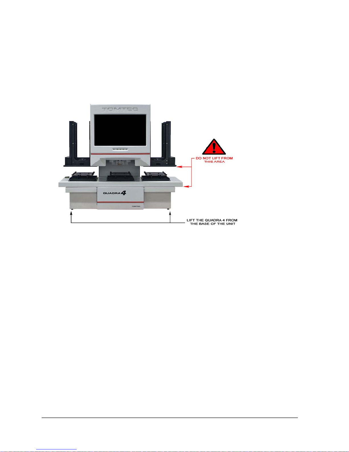
Carefully remove the Quadra 4 from the shipping carton and place on a level surface.
When moving the equipment, lift only in the locations indicated by Figure A. Do not lift or
handle the equipment by the X-Y table.
Locating the Quadra 4
When selecting a suitable place to set up your Quadra 4, please consider the
following:
The Quadra 4 should be placed on a level surface. A slanted surface can cause the
liquid to pool to one side of a well or reservoir and may impair your ability to fully
pipette out small volumes.
Be sure to leave at least four inches (10 centimeters) between the back of the
Quadra 4 and any wall or shelving that may impair the movement of air through the
cooling fans.
Although the Quadra 4 can supply its own air pressure, some accessories may
require a water source (normally DI), a vacuum source, a place to drain waste liquid,
or additional space for a vacuum trap or controller module.
For overall space requirements, please refer to the instrument dimensions under
"Physical Specifications" on page 12.
Quadra 4 Operator Manual
10
Tomtec
Page 11
Section I - General Information
CAUTION: IF THE EQUIPMENT IS USED IN A MANNER NOT SPECIFIED
BY THE MANUFACTURER, THE PROTECTION PROVIDED BY THE
EQUIPMENT MAY BE IMPAIRED.
The Quadra 4 is designed for use with various liquids, aqueous
or organic solutions with a pH near neutral. As the pH of the
solution moves away from neutral, various parts may be
affected, depending on the length of time they are in contact.
The user has full responsibility for the selection of compatible
liquids and for thoroughly rinsing the system after use. Damage
resulting from improper use of liquids and lack of cleaning are
the user's responsibility and may void the warranty.
Important Note:
Powered accessories such as Vacuum Traps, Autotraps and
Shaker Nests, should not be connected with the Quadra 4
powered on. Please turn off AC power
these accessories.
BEFORE
connecting
Quadra 4 Operator Manual
11
Tomtec
Page 12

Specifications & Technical Information
QUADRA 4
Environmental Specifications
Operating environment
INDOOR USE ONLY
Temperature 5ºC to 40ºC (41 ºF to 104 ºF
Humidity: 20%-90% (no condensation)
Storage environment
INDOOR USE ONLY
Temperature: 0 °C to 60 °C (32 °F to 140 °F)
Humidity: 5%-90% (no condensation)
Physical Specifications
Dimensions:
Width: 30” (762 mm)
Depth: 21” (534mm)
Height: 33” (838mm)
Weight: 200lbs (90.71kg)
Shuttle Extension: 9.5” (241mm) L/R
Shuttle Extension: 6” (153mm) (Front to Back)
Electrical Specifications
Power requirements:
100VAC NOM, 60Hz @ 4.0 AMP
105-125VAC 60Hz @ 4.0 AMP
230-240, 50Hz @ 2.0 AMP
Pneumatic Specifications
Internal Compressed Air
Quadra 4 Operator Manual
12
Tomtec
Page 13
Warnings, Cautions, Notes, & Symbols
Throughout this manual, there may be blocks of text printed in bold type within boxes
or italic type. These blocks are warnings, cautions, and notes, and they are used as
follows:
WARNING:
AND TELLS YOU HOW TO AVOID THE PROBLEM.
CAUTION:
HARDWARE OR LOSS OF DATA AND TELLS YOU HOW TO AVOID THE
PROBLEM.
NOTE: A NOTE indicates important information that helps you make better
use of your Quadra.
A WARNING INDICATES THE POTENTIAL FOR BODILY HARM
A CAUTION INDICATES EITHER POTENTIAL DAMAGE TO
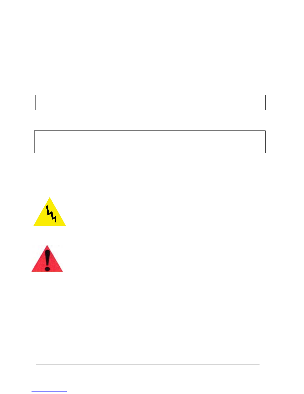
In this manual, there may be symbols within triangles, and they are used
as follows: The lighting flash with arrowhead symbol, within an equilateral
triangle, is intended to alert the user to the presence of un-insulated
"dangerous voltage" within the product's enclosure that may be of
sufficient magnitude to constitute a risk of electric shock.
The exclamation point within an equilateral triangle is intended to alert the
user to the presence of important operating and maintenance (servicing)
instructions in the literature accompanying the instrument.
Quadra 4 Operator Manual
13
Tomtec
Page 14

Introduction
The TOMTEC Quadra 4 is a third generation liquid handling workstation with
numerous optional pipetting head configurations available with or without stackers,
formatting stage selections and protocol specific accessories. Your local TOMTEC
Sales Engineer or our Worldwide Distribution Network can offer customer assistance
in selecting the correct model, pipetting head and accessories to fit individual
requirements.
The Quadra 4 incorporates an embedded PC, 15" full Color Display, our unique
Quadra 4 Command Software, and wireless keyboard. In addition, the embedded
PC provides 4 USB ports and internet network capabilities.
This manual will describe the standard Quadra 4 Pipettor - both with or without
stackers. Additional pipetting head configurations and stage options are outlines in
APPENDIX A at the end of this manual.
An electronic copy of this manual is provided in PDF Format and is resident on the
internal hard drive in the instrument.
Login Instructions
The Quadra 4 uses the login functions available with the MS Windows 7® Operating
System installed in the embedded PC. This feature gives the user the option of
setting operational privileges and parameters for each individual using the Quadra 4.
The Quadra 4 shipped to you has a default login with administrator privileges :
administrator (PW = password)
tomtec (PW = Tomtec)
Privileges of defaults:
administrator – full application and MS Windows privileges
tomtec - operation of application programs
- create application programs
- upload and download USB ports
The Administrator can add, delete, change users, functionality, passwords, etc. by
using the MS Windows 7 functions (control panel – user accounts).
Quadra 4 Operator Manual
14
Tomtec
Page 15
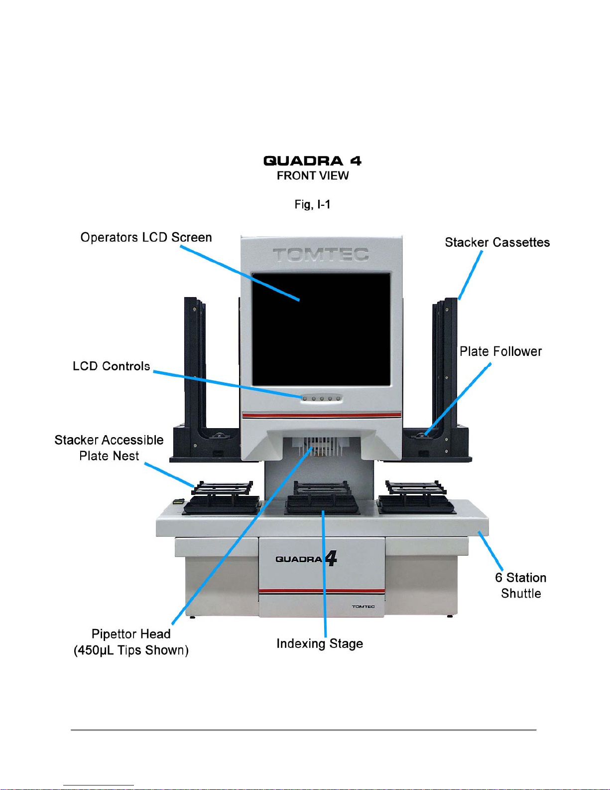
Quadra 4 Pictorials
Quadra 4, Front View
Quadra 4 Operator Manual
15
Tomtec
Page 16
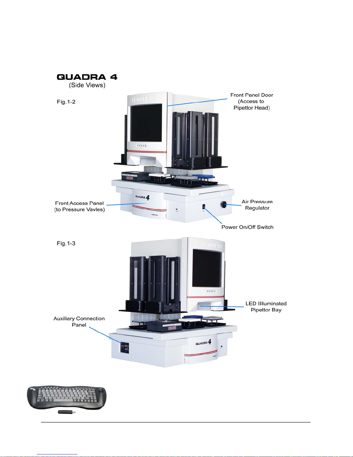
Quadra 4, Side Views
Quadra 4 Operator Manual
16
Tomtec
Page 17
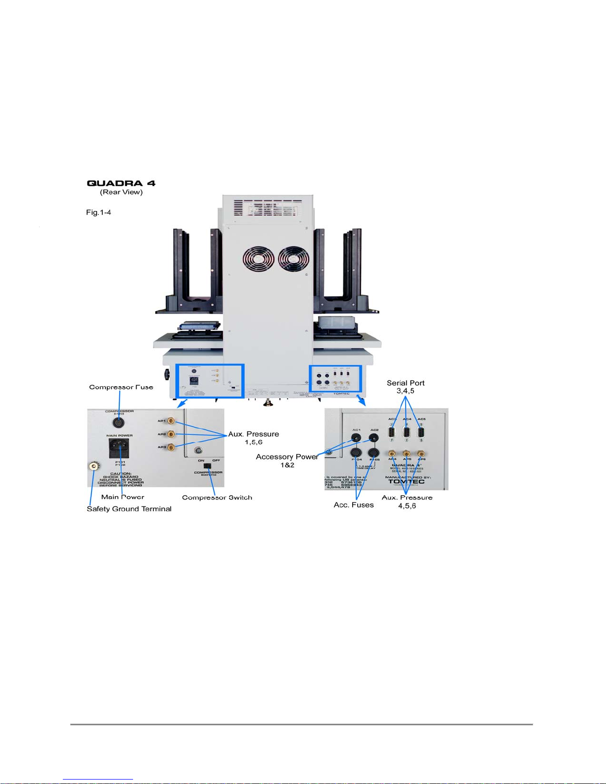
Quadra 4 (with stackers), Rear View
Quadra 4 Operator Manual
17
Tomtec
Aux.
Pres
sure
Page 18
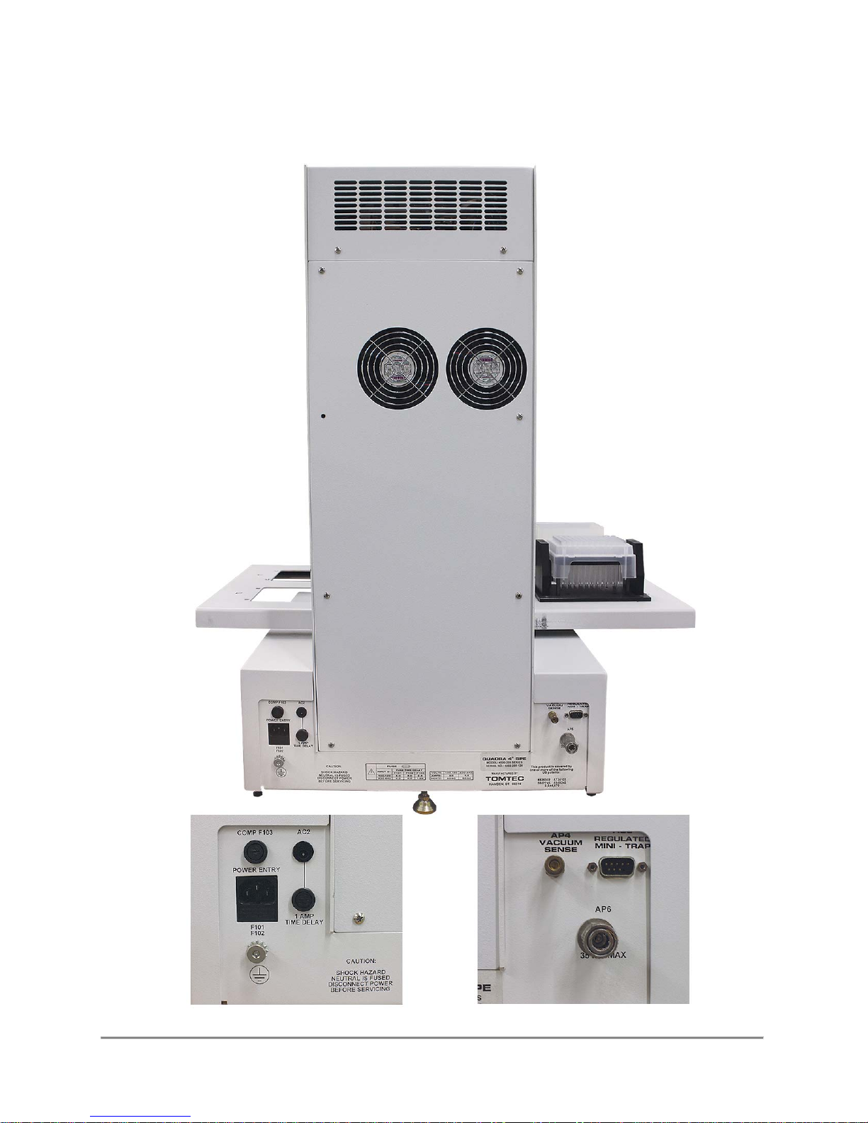
Quadra 4 (without stackers)
Quadra 4 Operator Manual
18
Tomtec
Page 19
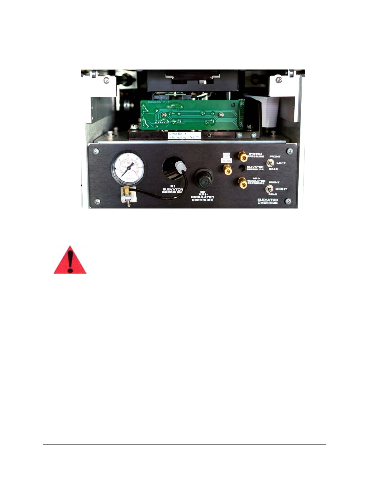
Quadra 4 Access Panel
(Front Access Panel)
Recommended to be used by TOMTEC Service Technicians only!
Quadra 4 Operator Manual
19
Tomtec
Page 20

Compressor & Pneumatics
Pneumatic Panel Description
The front panel provides manual access to the pneumatic system. The pressure gauge
may be connected to several ports for readout.
Compressor Pressure: 30psi for 60 Hz operation.
25psi for 50Hz operation.
NOTE: Due to normal compressor pulsing, do not leave the pressure gauge connected
to the compressor for long time periods. This affects the life of the pressure gauge.
Blowout Pressure: This is set by the regulator on the right hand side of the
Quadra 4. It will range from 0psi to 5psi. A more accurate
pressure reading is available on the front display.
Elevator Pressure:
Regulatory Accessory (API) Pressure:
At system pressure (not a user adjustment).
This pressure is set by the R2 pressure regulator.
It must be less than 10psi or it will rupture the bladder in the various nests.
Switches: Elevator Override - Actuates the stacker elevators.
Compressor Bypass:
Shuts off the internal air compressor and connects system to external air
supply. External air supply must not exceed 35psi.
Quadra 4 Operator Manual
20
Tomtec
Page 21

Section II - Operational Functionality
Pipetting System
The pipettor pistons are driven by a software controlled stepper motor. To provide
precise control it requires 400 half steps of the motor to make one revolution. This in
turn drives the syringe pistons aspirating or dispensing fluid. On the 96SV and 384 head
the pistons extend to the bottom of the pipette tips. This provides positive displacement
pipetting, essential for sub-microliter dispensing. The 450µL disposable tip head is an air
displacement system, providing up to 450µL dispensing.
Upon initialization, the stepper motor drives the piston up to actuate a photo sensor.
This is the home position for the volume counter. It then counts down to the zero volume
position for the pistons. Aspirate and dispense volumes are made by counting up or
down. You must always dispense an equal volume that has been aspirated. If you try to
dispense more than you have aspirated, "Pump Range" error will occur. If you do not
dispense the full amount aspirated, the accumulation will again cause "Pump Range"
error.
There are four speeds for the head motor. It is recommended that you always use speed
3, unless you are aspirating or dispensing viscous liquids. These may not flow through the
tip orifice in the time allowed at speed 3, especially, with the 0.015 inch diameter of the
small volume tips on the 96SV and 384 head.
The 450µL head has the ability to count below zero volume to remove the tips. There is a
software number that determines this function. It drives the tip stripper plate down to or
below the "O" ring to strip the tips from the tip pins. Each time the stripper plate moves
down, it applies a very light coating of lubricant to the tip pin "O" rings.
When loading tips, a sensor detects whether the tips have been fully sealed, thereby
preventing error in the pipetting volumes. If this sensor does not actuate, the stage will try
three times to load the tips properly. If it fails after the third time you are asked to use the
manual lubricator on the tip pin "O" rings. If this occurs frequently it is time to replace the
internal lubrication pad.
The design of the Quadra tips is unique. The long narrow portion (90µL) allows pipeline
pipetting, permitting you to aspirate several reagents sequentially using small air gaps for
separation. This, combined with the multiple stations on the Quadra 4 shuttle, means all of
the reagents can be added in one pass. The larger volume buffer can be used to wash out
the smaller volume of the compound. The 450µL volume of the Quadra tips also permits the
larger tasks, such as Solid Phase Extraction, Liquid/Liquid Extraction, or Protein Precipitation.
The Quadra tips (PN 196-205) are available with a standard orifice size 0.036”, as both
sterile, and non sterile. The Quadra tips are retained in their rack. This permits handling
them as a single unit, not individual tips. They may be used, shucked as a unit, and
reused.
Quadra 4 Operator Manual
21
Tomtec
Page 22
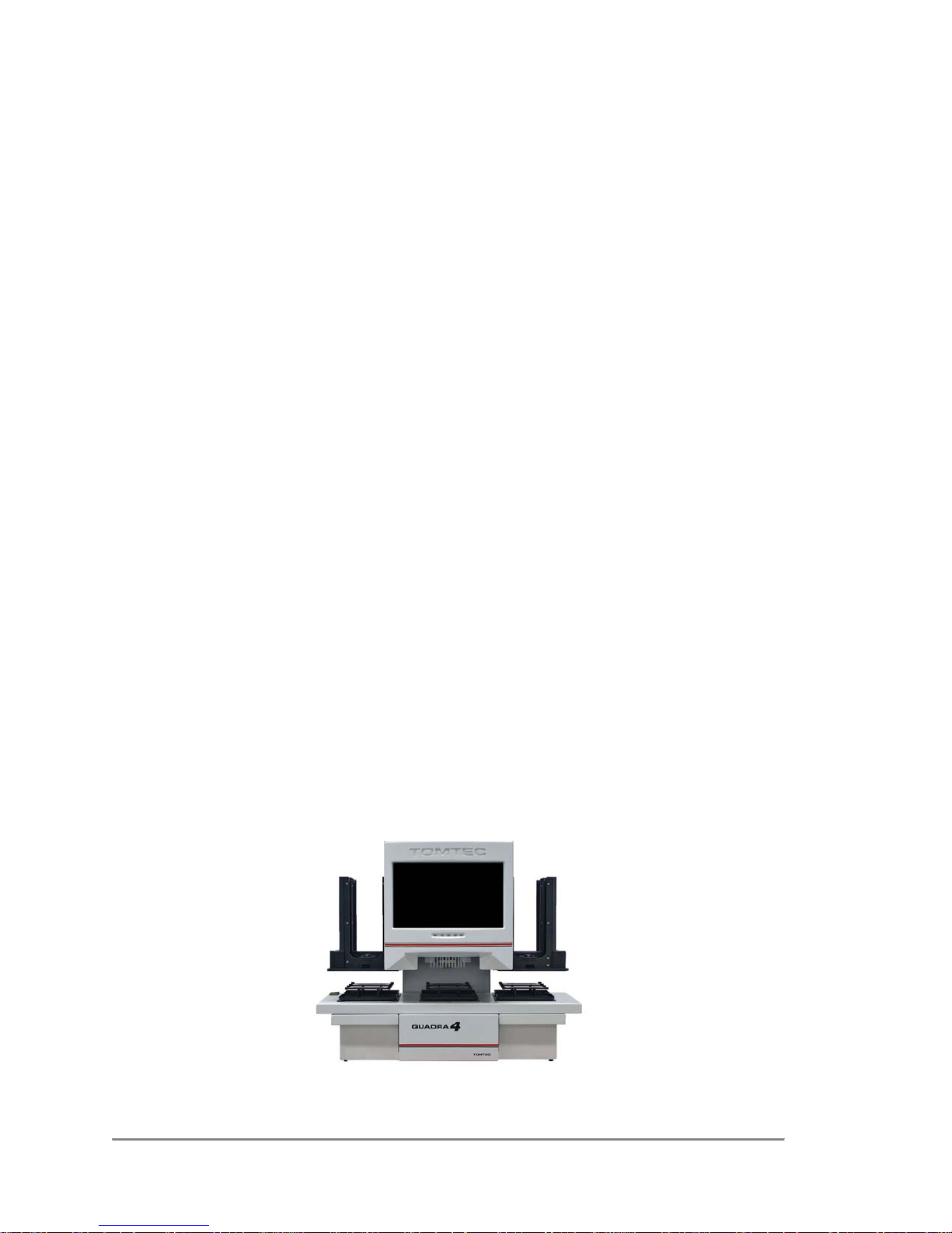
Quadra 4 General Information
Tomtec uses a different design philosophy on the Quadra 4 compared to most
competitive multi-well pipettors. Rather than move a complex, heavy, pipetting head
over the microplates, the Quadra design fixes the head firmly in one place. The shuttle
is used to move lightweight plates and reservoirs to the stationary head. This results
in a very reliable design. All of the electronic control wiring is fixed in place. Moving
wiring is subject to breakage. An intermittent breakage in a control line is extremely
difficult to diagnose. This has the additional advantage of being able to easily change
the pipetting head for very different applications. Four bolts and a plug in connector
complete the change over.
The 6-station shuttle, under software program control, can quickly position any station
under the pipettor head. More importantly, the shuttle can be automatically loaded and
unloaded via the stackers for those applications requiring the processing of more than
6 devices. Thus, in comparison to large flat bed pipettors, the Quadra design can
handle 50 devices, plates and reservoirs, to and from the pipettor with walk away
automation.
A stage is provided under the pipettor head to lift the various devices to the tips for
precise vertical control. Depending on the application, this can be a simple stage with
touch off control or it may be a full indexing stage for reformatting or serial dilution
testing protocols.
The straight forward design of the Quadra 4, lends to very easy and intuitive software
control. Complex protocols requiring various microplates and reservoirs can be
created to run in a walk away mode of operation, while only requiring 30 inches of
bench top space.
Tomtec has elected to supply the Quadra 4 in a variety of configurations. This is to
allow the end user the freedom of selecting the most cost effective model for their
specific requirements. This operator's manual describes the various elements that are
available. Not all of these features are on all models.
This is our top of the line model. It includes stackers, an indexing stage, and has a full
pneumatic system for use with additional accessories.
Quadra 4 Operator Manual
22
Tomtec
Page 23
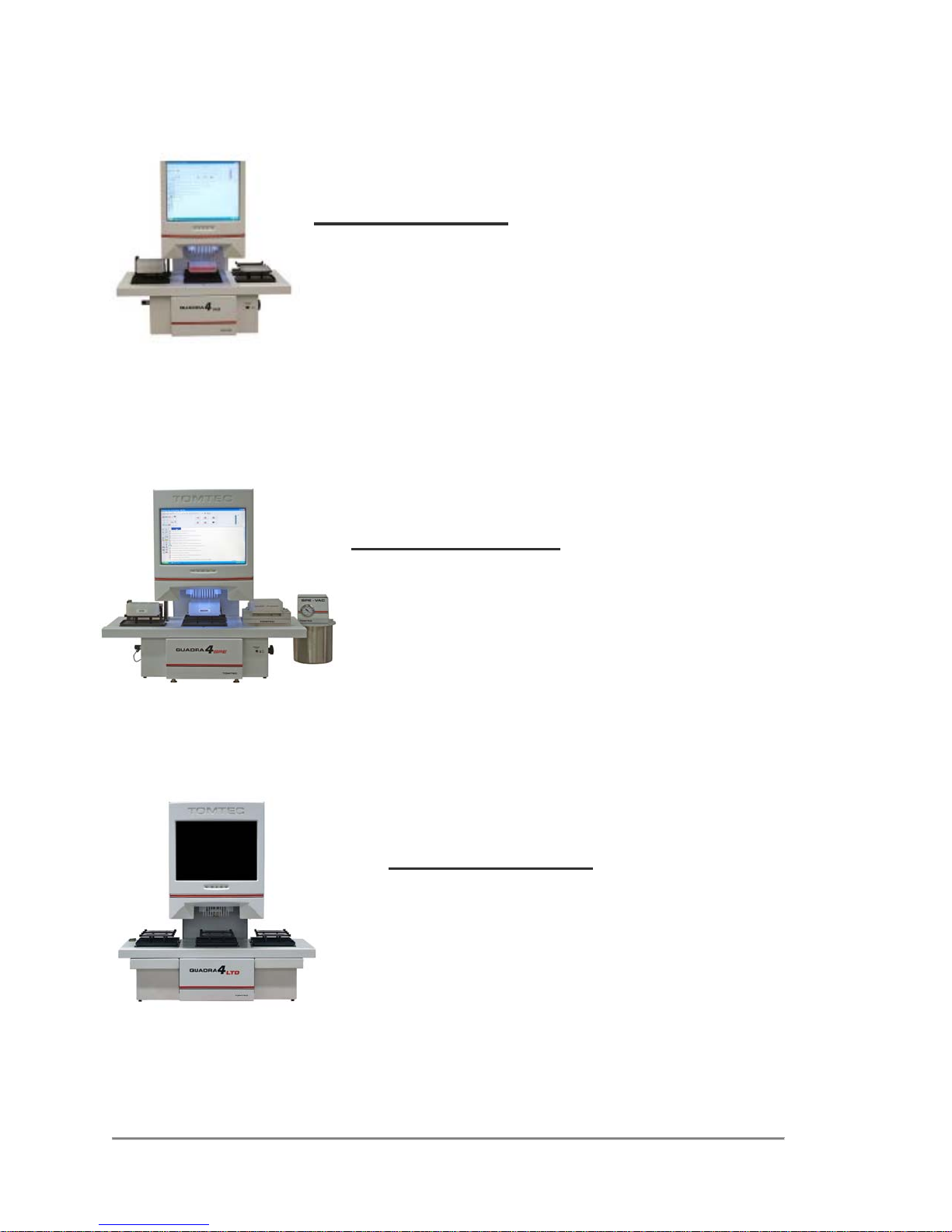
Quadra 4 Product Line
QUADRA 4 NS
This is the Quadra 4 without the stacker option but with the
indexing stage for reformatting i.e., 96 to 384 to 1536. It does not
have the full pneumatic system of the Quadra 4.
QUADRA 4 SPE
Similar to the Quadra NS, this model is also without stackers.
The indexing stage has been replaced with a touch off stage.
A manually operated vacuum box and vacuum trap is
included. The Quadra 4 SPE is designed for solid phase
extraction applications. It has the ability to blow nitrogen
through the tips for sample dry down. It has a limited
pneumatic system.
QUADRA 4 LTD
This is the same as the Quadra 4 SPE Model except it
does not have the vacuum box and vacuum trap include
Quadra 4 Operator Manual
23
Tomtec
Page 24
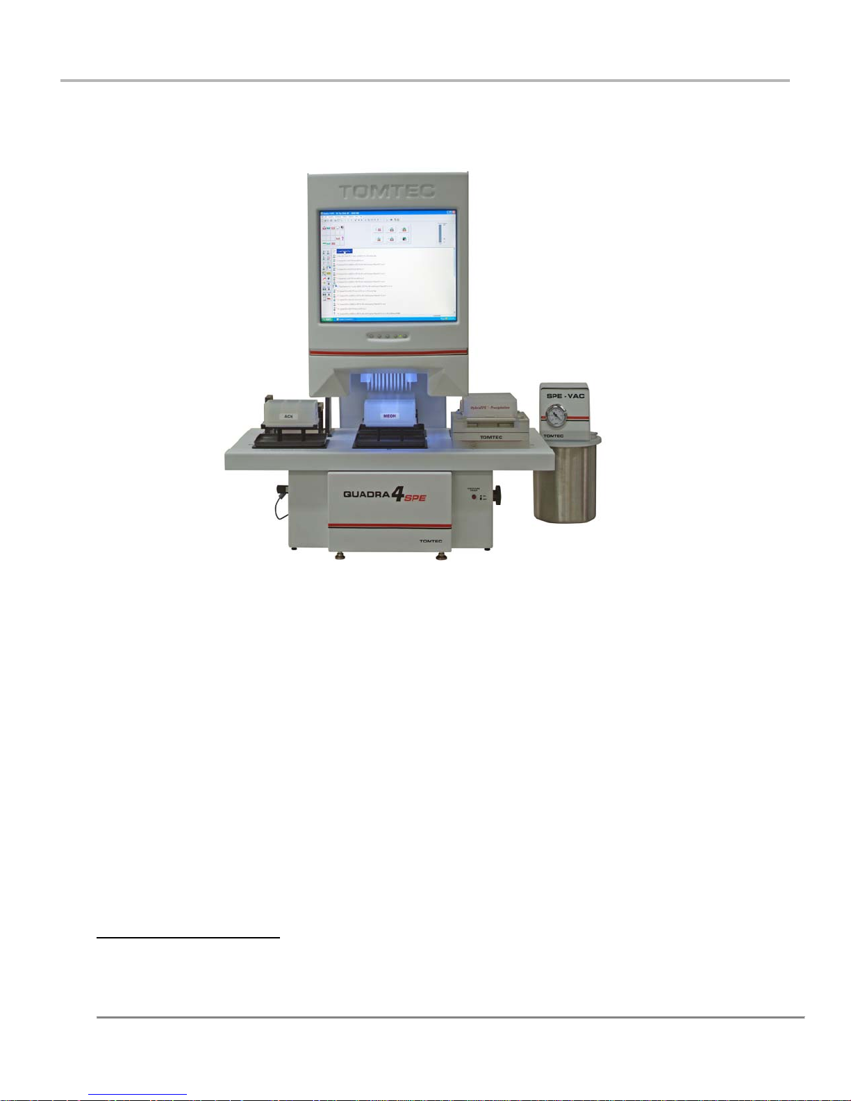
Section III – Quadra Command System Op Manual
Quadra Command System v4
Current Version Level 4.8.x
Copyright © 2015. All rights reserved.
TOMTEC, Inc.
1000 Sherman Ave.
Hamden, CT 06514
Phone: (203) 281-6790
Fax: (203) 248-5724
http://www.tomtec.com
Quadra 4 Operator Manual
24
Tomtec
Page 25

1.0 Introduction
1.1 What's New
The Quadra 4 Command Software contains several enhancements and improvements
over previous versions of the software.
Version 4.8.0
The Quadra Command Software now runs on a Windows® 7 platform.
The Drag and Drop operations have been changed to simple point and Click
operations.
Aspirate, Dispense and similar functions have simplified Dialogs.
The Labware names which are assigned to Shuttle locations, are now displayed
on the screen.
All of the Labware and Program Functions Icons can now be displayed as Text
messages, Icons or both.
The Labware and Program Functions which are not valid for the currently
highlighted shuttle location can be displayed as disabled buttons, or not at all.
This makes it more straight forward as to which functions can be used in certain
situations.
Version 4.7.7.30
The number of Tip Loads is now displayed on the main screen.
Version 4.7.7.29
The ability to validate the processing of mirror racks which have been processed
with the Tomtec PSID2 software.
Most of these changes are discussed in the next sections.
Quadra 4 Operator Manual
25
Tomtec
Page 26
1.2 Major Changes to the Quadra 4 Command Software
1.2.1 Drag and Drop Operations
When adding labware to a Shuttle Position it is no longer necessary to Drag the labware
item and Drop it onto a Shuttle position. Instead simply click the desired Shuttle
Position and then click the Labware Item(s) to be placed there.
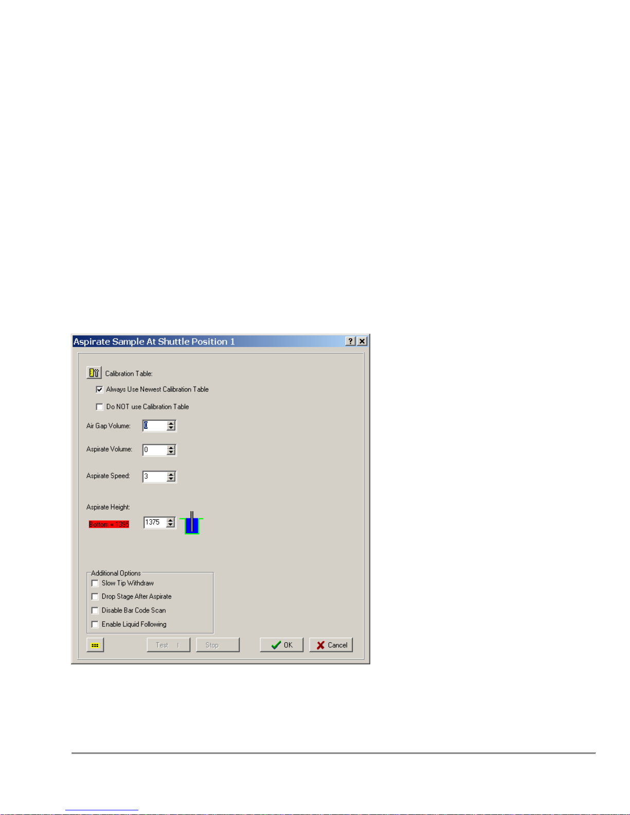
1.2.2 Simplified Dialogs
All of the Dialogs which involve Aspirating or Dispensing have been significantly
modified.
For example, here is a sample Dialog for adding an Aspirate from the 4.7.x Command
Software
In Version 4.8 Software, the settings are now separated into three Tabs, “Basic
Settings”, “Advanced Settings” and “Stage Operations” as shown below.
Quadra 4 Operator Manual
26
Tomtec
Page 27
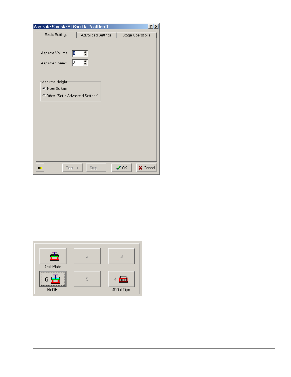
Only the most basic information, the Volume, Speed, and Height are displayed on the
first tab. All of the other information is available on the other two tabs.
1.2.3 Shuttle Labware Labels
The names associated with the Labware assigned to each Shuttle Position can now be
displayed in the Shuttle Area of the Main Screen as shown below.
These names can be assigned when the Labware is added to the Shuttle Position, or
can be added or changed by Right Clicking on the Shuttle Position icon and selecting
the "View/Edit Labware" option.
This option can be enabled or disabled through the System Parameters → View
Preferences Dialog.
Quadra 4 Operator Manual
27
Tomtec
Page 28
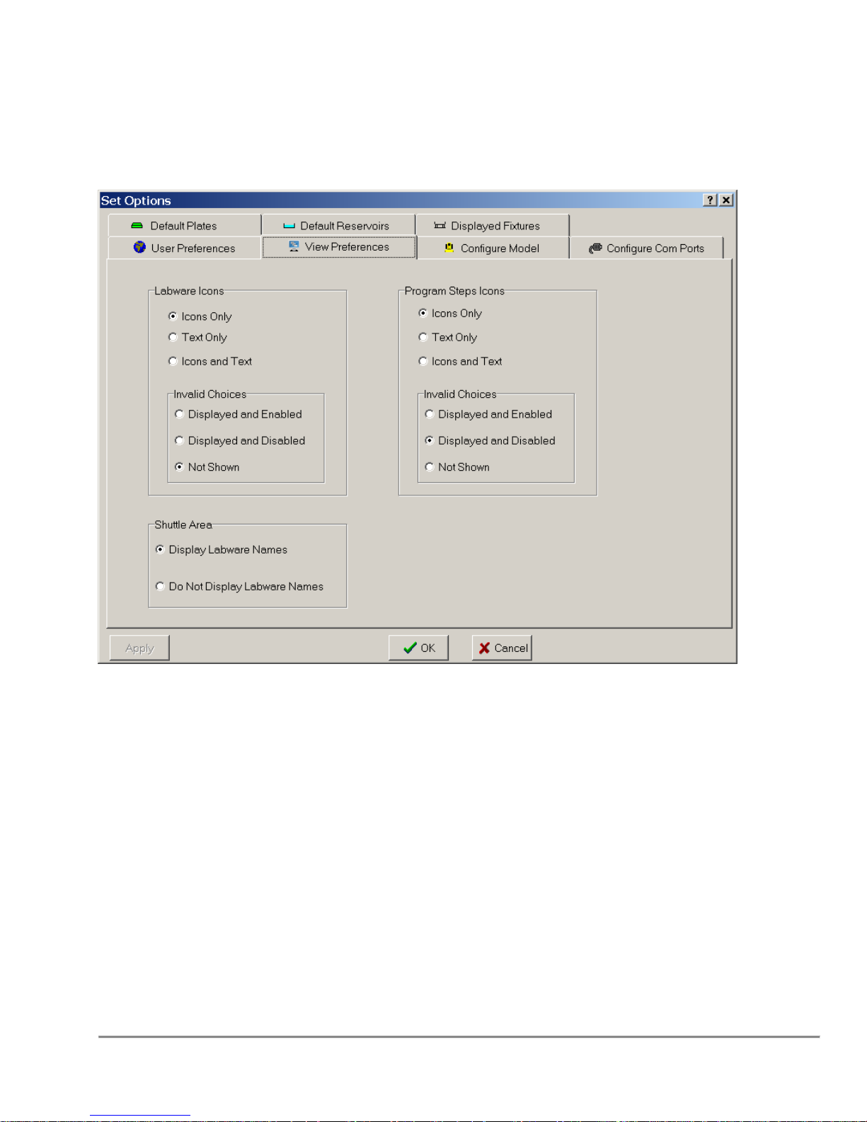
1.2.4 Labware and Program Function Icon Changes
The way which the Labware and Program Function Icons are displayed can now be
selected thought the System Parameters -> View Preferences Dialog as shown below:
The Labware icons and the Program Step icons can be displayed as:
Text Only
Icons Only
Text and Icons
In addition, if there are choices which are not currently valid for the Currently Selected
Shuttle position, those choices can be:
Displayed, but grayed out and non-selectable
Displayed and selectable
Not Shown
When using the "Not Shown" option, it is important to note that the Labware Icon area
will be completely EMPTY when the program is started. The appropriate icons will only
be displayed with a Shuttle Position is highlighted.
Quadra 4 Operator Manual
28
Tomtec
Page 29
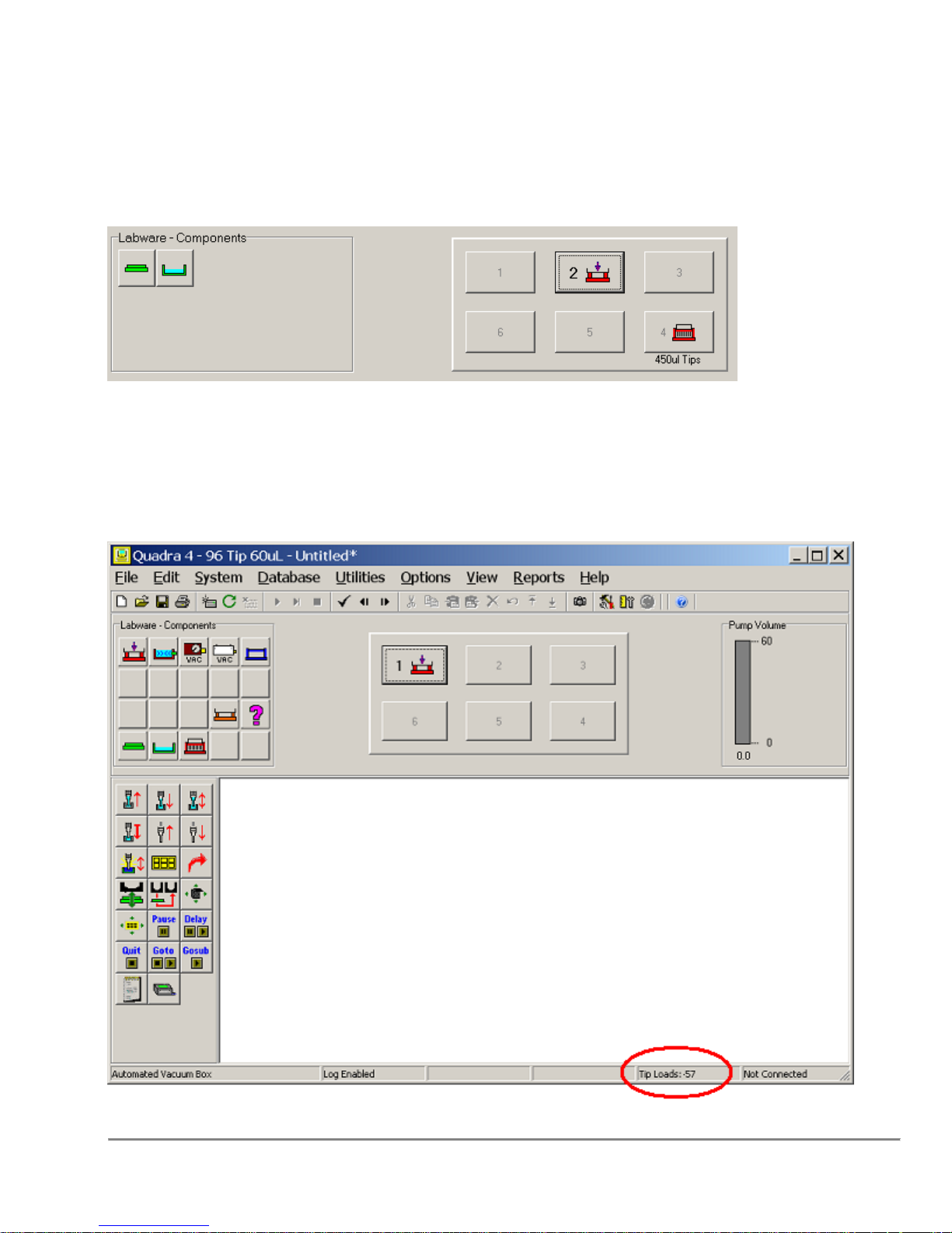
When using the "Displayed and Enabled" option, an error message will be displayed
when an invalid choice is selected.
Is the example below, the Labware Icons were chosen to be displayed as "Icons Only"
and the invalid choices are set to be "Not Shown".
Shuttle Position 2 is highlighted (as shown above) which already contains a Stacker
Nest. Therefore, the only valid Labware choices are Microplates and Reservoirs thus
these are the only two icons shown.
1.2.5 Tip Load Counter
Quadra 4 Operator Manual
29
Tomtec
Page 30

A counter has been added to the main screen which displays the total number of Tip
Loads. This can be used to determine if it is time to lubricate the “O” rings.
The counter is displayed in the status bar at the bottom of the main screen as shown:
The counter can be reset by using the System → Reset Tip Load Count function. This
should be reset when the “O” rungs are replaced or lubricated.
1.2.6 PSID2 Mirror Rack Checking
If Black and White Mirror Racks are being used in a protocol which have already been
processed with the Tomtec PSID2 device, the Quadra 4 can be setup to validate the
handling of these racks to ensure that they are being processed correctly.
The Quadra 4 software can validate that:
1. The Mirror Racks and the Destination Plate have been placed onto the Quadra in
the correct orientation.
2. The Black Mirror Rack, the White Mirror Rack, and the Destination Plate
barcodes all match the values specified within the PSID2 software.
In order to use this validation, a barcode reader must be installed on the Quadra 4 on
the RIGHT side of the pump.
Transferring the PSID2 Files
To begin, the Completed Main Operating File(s) need to be copied to the Quadra 4.
The files are saved on the computer running the PSID 2 Software in the directory:
C:\tomtec.psid2\psid2\archive\
Only the COMPLETED CSV files should be copied. These files have the naming
convention of:
<DestinationPlateBarcode>_MOF_<BlackRackBarcode>_<WhiteRackBarcode>_<Date/Time>.csv
These files should be copied to the directory on the Quadra 4,
C:\Program Files\Tomtec\Quadra 4 Command System v4\PSID2\
Quadra 4 Setup
Before running the protocols on the Quadra, the Mirror Rack Checking needs to be
enabled.
Quadra 4 Operator Manual
30
Tomtec
Page 31
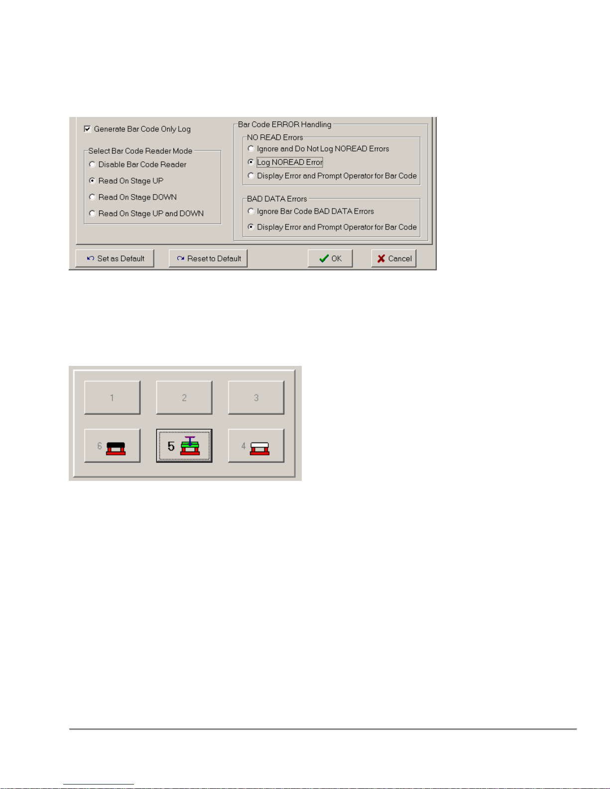
In the Options → User Preference dialog, set the “Mirror Rack Checking” value to
“enabled”.
In the File → Log Settings dialog, ensure that the following settings are being used:
and use the “Set as Default” button to save these settings.
The shuttle positions of the Black and White mirror racks should be specified (see
below), so the Quadra code knows where to look for each of these racks.
Running a PSID2 protocol
Running a protocol with Mirror Rack Checking enabled is done the same way as
running any protocol on the Quadra 4. However, during the run, the Quadra software
will scan the barcode of the incoming rack and look to find the corresponding PSID2 file
in the above directory. The software will then check the barcode of the other mirror rack,
and the destination plate to ensure that they match the expected barcodes and that they
are oriented correctly on the Quadra shuttle. If no barcodes are read, or if an
unexpected barcode is encountered an error message will be displayed, and the user
will be asked to fix the problem and retry.
The Mirror Rack Checking code is looking for a single Aspirate from the White Mirror
Rack, a single Aspirate from the Black Mirror Rack (not necessarily in that order), and
one or more dispenses into the Destination plate. Once all of these requirements are
Quadra 4 Operator Manual
31
Tomtec
Page 32

met, the csv file is moved into a sub directory named “Completed” and the Quadra will
no longer check barcodes.
In some instances, it may be necessary to have additional steps within the protocol
when processing the Mirror Racks. Any additional steps in the protocol which are not
related to the standard mirror rack checking should have the "Disable Barcode Reading"
option checked. This will cause that step to be ignored by the Mirror Rack checking
code.
Also, it is important to note that the barcode will only be read correctly if the stage is all
the way down before the step starts. In some cases it might be necessary to set the
option to "Drop Stage after Dispense" in the step BEFORE the step which checks the
barcode.
1.3 Quadra 4 - Getting Started
Creating a stacker program on a Quadra 4 is a multi-step process and there are
certain rules that apply. The objective is to create a smooth running program
that can be repeated on demand. The real advantage of automation is to create
a specific protocol, that will run precisely the same, every time. This allows small
optimizing modifications that will be faithfully reproduced to enhance the end results.
Once the program is created, anyone can execute it. The stackers are loaded in the
defined order of the program and then executed precisely the same every time the
protocol is run.
Not every Shuttle Station can access all of the stackers. Shuttle station 2 is the most
flexible. It can access all four stackers. Station 1 can access the Left Rear
Stacker (LRS) and the Left Front Stacker (LFS). Station 3 can access the Right
Rear Stackers (RRS) and the right front stacker (RFS). Station 5 can access the LFS
and RFS. Stations 4 and 6 can only access a single stacker each, the LFS and the RFS
respectively. Thus, they are the least flexible. Therefore, they are commonly used for
fixed functions, such as the Ultrasonic Tip Wash Station or a vacuum box. They are also
useful for a common reservoir that is used through out the protocol.
While each pipetting protocol may be different, in general terms, it is effective to use the
left rear stacker for the incoming source plates, or reservoirs and the right rear stacker
for the destination plates. In this manner at the end of the sequence, the source plates,
or reservoirs may be restacked for the next set of destination plates. The tip boxes are
then interspersed, depending on whether they are to be assigned and reused with the
specific sources or not. A distinct advantage of the Quadra 4 is the ability to make a
non-contact dispense. The target method may be used to make a clean dispense at the
top of the well, without touching the contents of the receiving plate. This allows
assigning a rack of tips for use with specific reagents, without fear of cross
contamination.
As the pipetting protocol become more complex, moving microplates, reservoirs and
tips in and out of the stackers to the shuttle becomes more challenging. While
Quadra 4 Operator Manual
32
Tomtec
Page 33

everybody finds their own best way, a starting point is to step the protocol through the
entire program, step-by-step using the simple Quadra programming features. It
provides a visual presentation of the program as you proceed.
The program allows you to assign a descriptive name to each plate, reservoir, or rack of
tips. This aids in tracking the program. As each new device is placed on the shuttle, use
the shuttle layout icon to bring the appropriate database values. At the end, it is
essential that you record the starting location of each microplate, reservoir, or tip
rack in their respective stackers. This information may be recorded in an initial pause
statement.
Tomtec personnel are available to assist you in creating a stacker program.
When using this program for the first time check that:
1. The Calibration Height is set on all fixtures in use. These values can be set in the
Database Editor. Open the Quadra DBEditor by selecting Database → ‘Edit Plate,
... Database.’
2. The COM Port setting is correct. This can be set by going to the Options Menu →
Quadra → Configure COM Ports.
3. The proper machine model is selected. This can be set by going to the Options
Menu → Quadra → Configure Model.
Upon Connecting to the Quadra for the first time, the program will automatically
recognize the head configuration, and change its settings accordingly. Make sure,
before you start writing your protocol, that you have Configure Model set to the
right configuration, or simply connect to the machine before programming.
1.3.1 Preparing the Quadra to run a program:
1. Click the ‘Connect’ button on the Main Toolbar to establish the serial connection with
the Quadra.
2. After the connect operation is successful, the ‘Initialize’ button will enable. Click this
button to initialize the Quadra.
3. Be sure to include the proper fixtures on the shuttle layout before adding steps to
your program.
Quadra 4 Operator Manual
33
Tomtec
Page 34
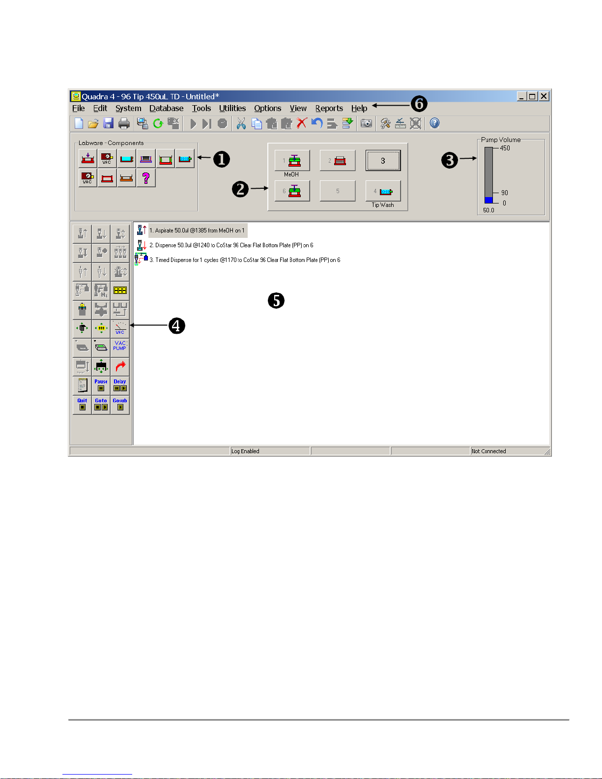
2.0 Main Screen
The Quadra Main Screen, shown above, contains Six major sections.
1. Labware - Components Area
2. Shuttle Layout Area
3. Pump Volume Box
4. Program Operations Box
5. Program Steps Area
6. Menu Bar
Quadra 4 Operator Manual
34
Tomtec
Page 35
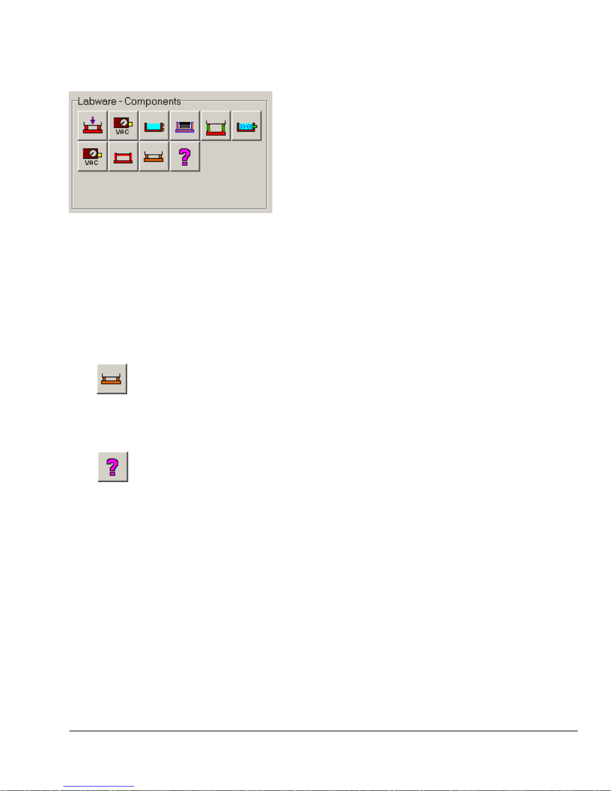
2.1 Labware - Components Area
Icons in this section represent the various plates and fixtures available. To assign labware
or a component to a shuttle position, first Click on the appropriate shuttle position in the
Shuttle Layout Area and then click on the desired Labware icon. This will update the
Shuttle Layout Area. The fixtures should be placed first. Plates, reservoirs, and tips are
then added in a similar fashion to fixtures already present at the desired shuttle position.
The fixtures which are displayed in this area can be modified using the Database ->
“Configure Displayed Fixtures” dialog (Refer to Section “5.8.1 Edit Display and Order of
Fixtures” on page 107). A maximum of 13 fixtures can be displayed in this area.
The, , icon in this section represents “Other Plate Capable Fixtures”. When this is
selected, a list will be displayed showing all of the defined fixtures which are NOT already
displayed in the “Labware – Components” area, AND which allow plates to be used with
them.
The, , icon in this section represents “Other Non-Plate Capable Fixtures”. When
this is selected, a list will be displayed showing all of the defined fixtures which are NOT
already displayed in the “Labware – Components” area, AND do not allow plates to be
used with them.
Additionally, the icons in this area can be displayed as Icons, Text Descriptions, or both
based on the settings in the “Options” → “User Preferences” Dialog under the “View
Preferences” Tab. Setting the icons to have the Text Descriptions may be useful for
users who are unfamiliar with all of the icons.
Quadra 4 Operator Manual
35
Tomtec
Page 36
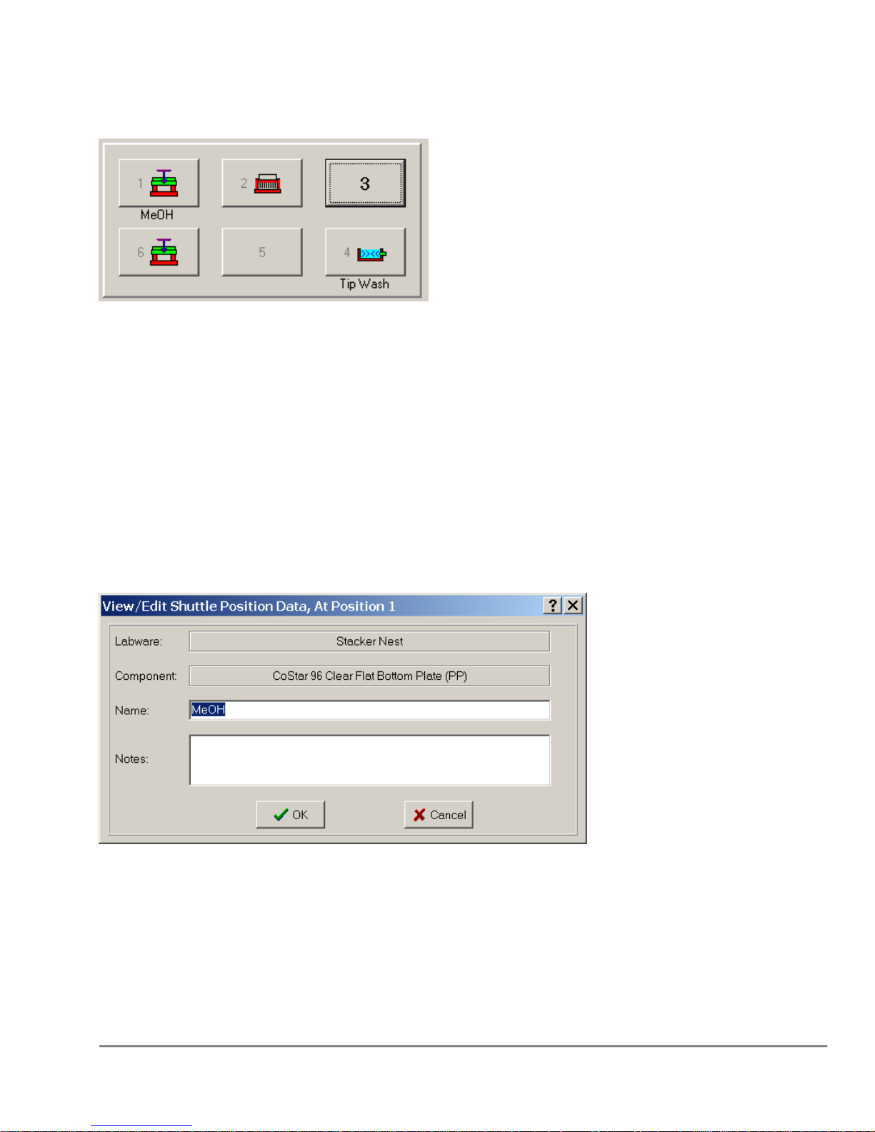
2.2 Shuttle Layout Area
This area displays the current shuttle layout. The images display either an empty fixture
or a fixture with a plate on top. To add a fixture, click on the shuttle location and then click
on the fixture to add. Plates and reservoirs are added in the same way. If a Name was
specified through the Shuttle Position Data dialog, it will be displayed under the
appropriate shuttle location.
2.2.1 Shuttle Position Data Dialog
This dialog box is accessible through a right mouse button click on the shuttle
position. Additionally user preferences can be modified to make this screen appear
whenever a fixture or plate/reservoir is placed on the shuttle on the main screen.
Labware - indicates the current fixture on the shuttle position.
Component - indicates the current plate or reservoir on the fixture.
Quadra 4 Operator Manual
36
Tomtec
Page 37
Name - indicates a user specified description of a shuttle position. Typically this is used
for describing the liquid contents of a plate or reservoir. If Name is not blank then it will be
used in place of the labware/components to describe the shuttle position on the main
screen and in the users program.
Notes - allows for any addition comments regarding the shuttle position. It is only
displayed in this dialog box.
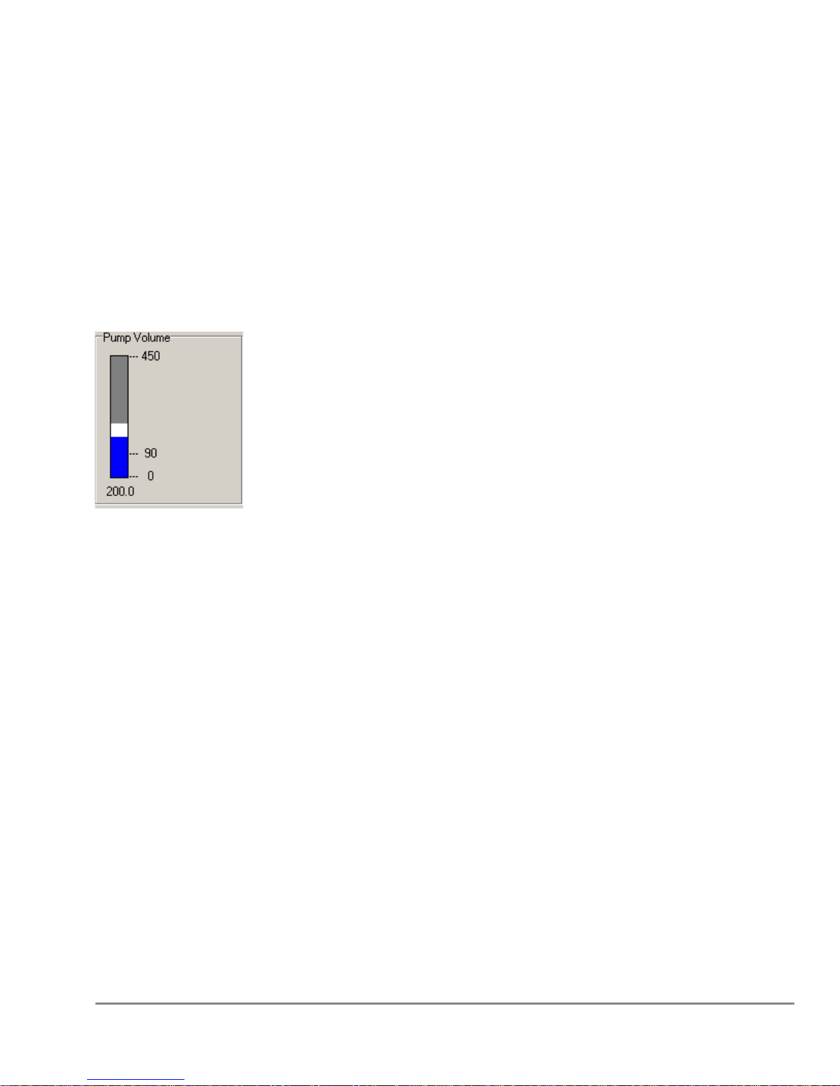
2.3 Pump Volume Box
The vertical progress bar indicates the volume in the tips.
When designing a program, it will show the current volume in the tips as if the program
has run to the currently highlighted step (volume is assumed zero at the start of
the program).
When running a program it will show the actual volume in the tips. White sections
represent volumes designed to be air-gaps. Blue and light blue sections represent liquid
volumes, aspirated separately.
The example above shows 50uL air gap with 150uL of liquid.
If "ERROR" is displayed, then either an over and under volume condition has occurred.
Quadra 4 Operator Manual
37
Tomtec
Page 38
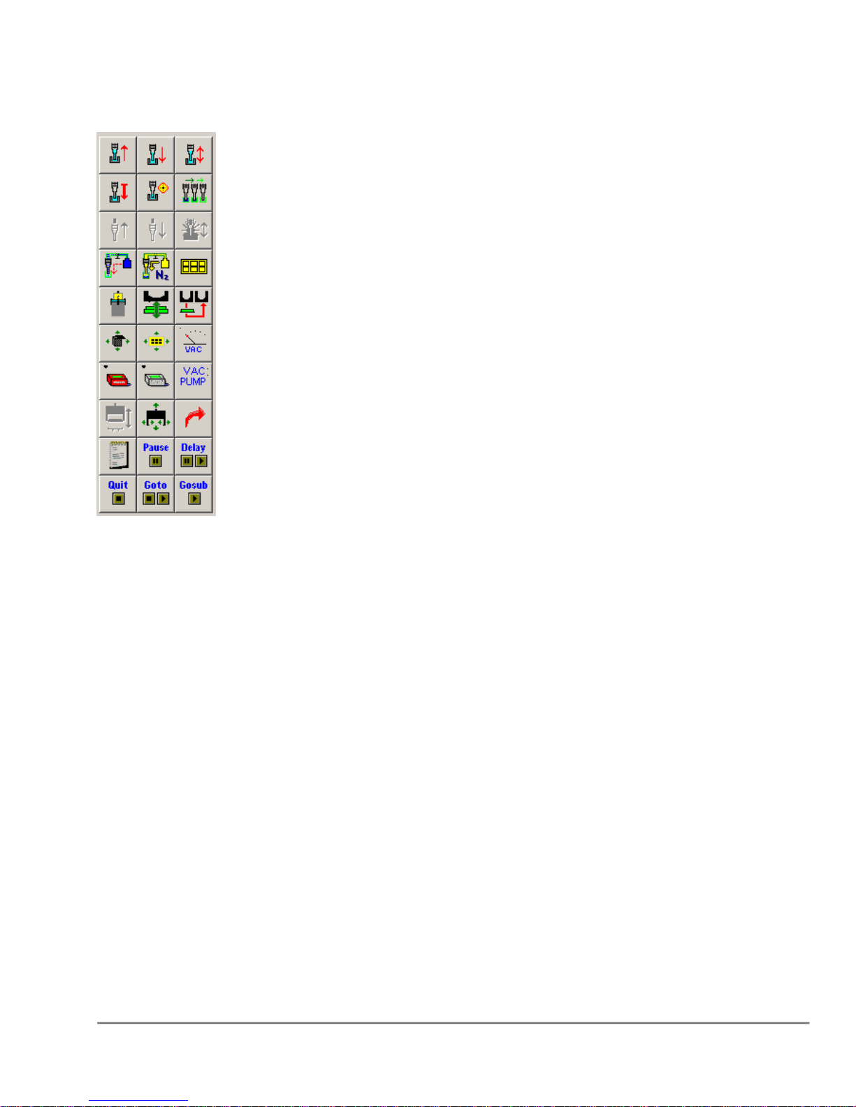
2.4 Program Operations Box
Icons in this section represent the various available functions for the current model
configuration. For example, if the configuration specifies that the Quadra does not
have stackers, then the stacker functions will not be displayed in this area.
Additionally, by default, functions which are not valid for the currently highlighted Shuttle
location will be grayed out and disabled.
These icons are used to generate the program steps in the adjacent Program Steps
Area. Typically to generate a program step:
1. Select the shuttle position by clicking on the shuttle graphic in the Shuttle Area.
2. Click on the icon for the desired function in this area. This will display the dialog
associated with the selected function.
3. Enter information into the dialog boxes and select OK.
For more information on manipulating the Program in the Program Steps Area, refer to
the next section.
All of the icons in this area can be displayed as Icons, Text Descriptions, or both based
on the settings in the “Options” → “User Preferences” Dialog under the “View
Preferences” Tab. Setting the icons to have text descriptions may be useful for users
who are unfamiliar with all of the icons.
Quadra 4 Operator Manual
38
Tomtec
Page 39
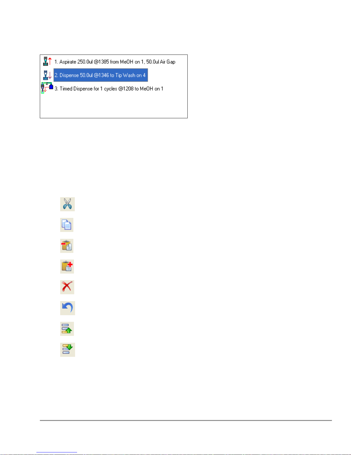
2.5 Program Steps Area
This area contains the steps of the current Quadra program. Each line represents a
single step in the Program. The icon on the left of each line represents the function
which is to be executed. This is followed by the Program Step Number, and a brief
description of the step.
Program steps can be manipulated by highlighting one or more lines in the program and
selecting one of the icons on the toolbar.
Cut the selected line(s)
Copy the selected line(s)
Paste the copied (or cut) lines before the current line.
Paste the copied (or cut) lines after the current line.
Delete the current line(s)
Undelete the most recently deleted line(s)
Move the selected line(s) UP in the Program
Move the selected line(s) DOWN in the Program
Program steps can be edited by double clicking on them, or by selecting the Edit →
“Edit Step” menu function.
Quadra 4 Operator Manual
39
Tomtec
Page 40
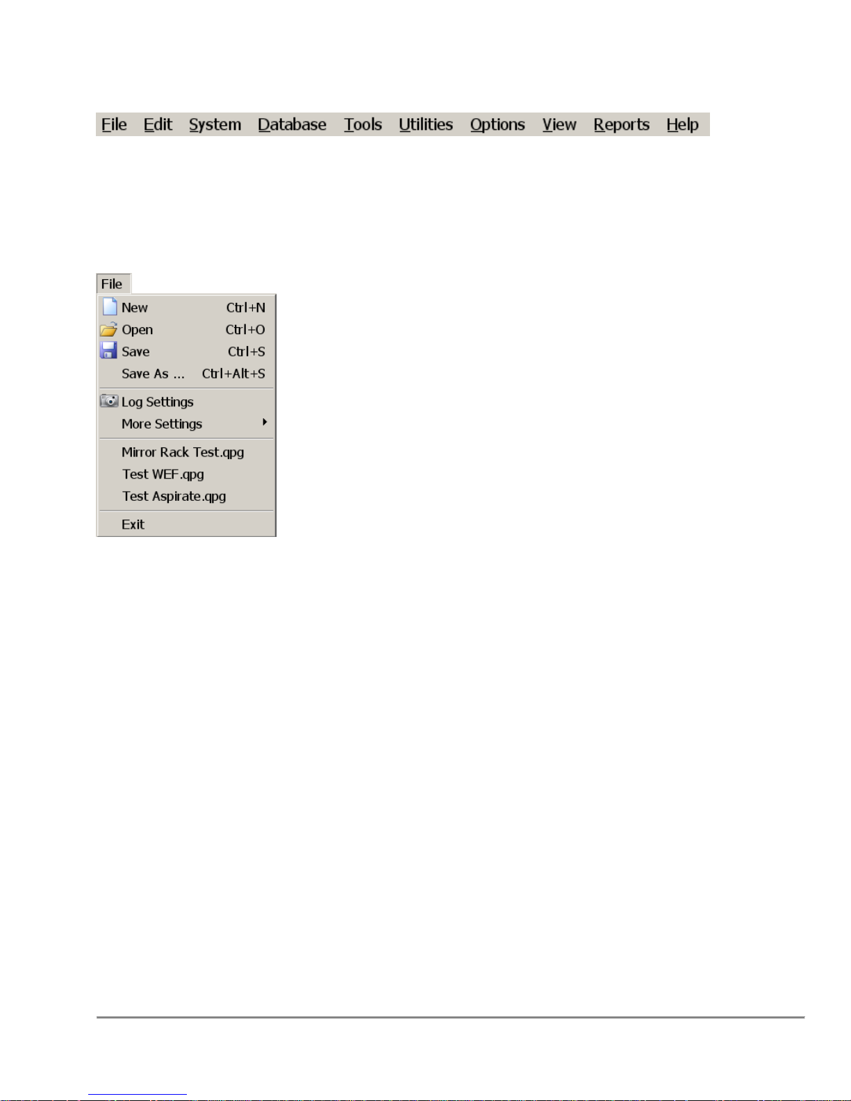
2.6 Menu Bar
The Quadra 4 Menu Bar (shown above) allows you to access many of the Quadra 4
functions. Each menu is described below.
2.6.1 File Menu
New - Clears the program window for new program entry.
Open - Opens an existing program.
Save, Save As - Saves any changes made to the program, and the "Save As" will allow
the program to be saved with a different name.
Log Settings – Refer to the Section “5.9.1 Logging Options” on page 108.
More Settings - Refer to the Section “5.9.2 Runtime Database Usage Options” on
page 109.
Recent Files - A list of the last used programs. Clicking on the entry will open the
program for you.
Exit - Exits the application.
Quadra 4 Operator Manual
40
Tomtec
Page 41
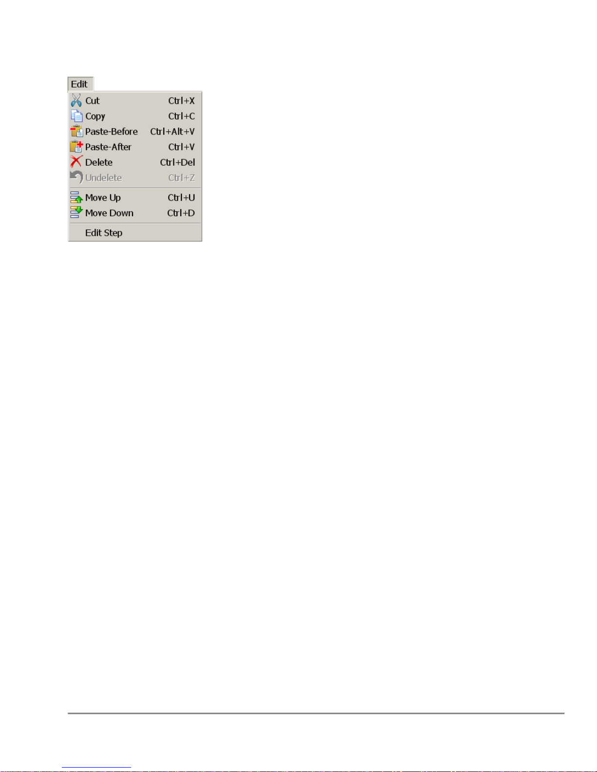
2.6.2 Edit Menu
Cut - Removes the selected line(s).
Copy - Copies the selected line(s) to the clipboard.
Paste-Before - Pastes the copied line(s) before the selected line.
Paste-After - Pastes the copied line(s) after the selected line.
Delete - Deletes the selected line(s).
Undelete - Undeletes the last line(s) deleted.
Move Up, Move Down - Moves the selected line(s) either up or down in the program.
Edit Step - The selected step's function dialog window will be displayed for parameter
changes.
Quadra 4 Operator Manual
41
Tomtec
Page 42
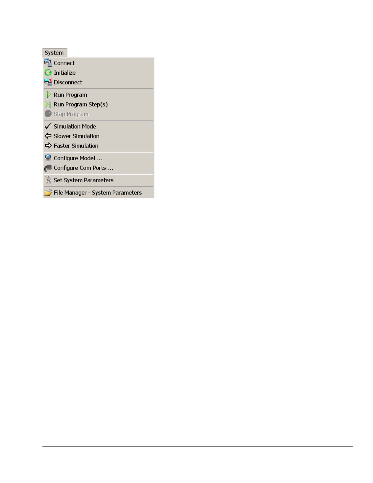
2.6.3 System Menu
Connect - Connects to the Quadra verifying and setting runtime parameters.
Initialize - Initializes the Quadra to a known state.
Disconnect - Disconnects from the Quadra.
Run Program, Run Program Step(s) - Runs the displayed program or runs selected
steps in the displayed program.
Stop Program - Stops/Aborts the program. note that the program may have to
complete the current action before aborting.
Simulation Mode - Simulation Mode is used to verify that the pump volumes are
correct.
Configure Model – Refer to the Section “5.4 Configure Model”on page 103.
Configure Com Ports – Refer to the Section “5.5 Configure Com Port” On Page 104
Set System Parameters - Refer to the Section “9.0 System Parameters” on page 132.
Quadra 4 Operator Manual
42
Tomtec
Page 43
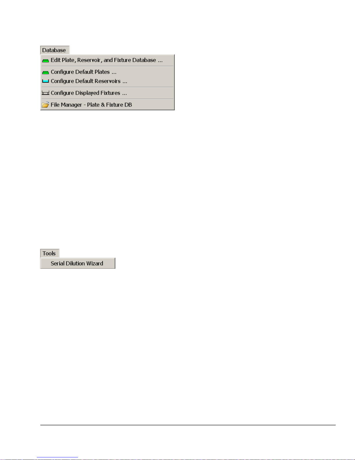
2.6.4 Database Menu
Edit Plate, Reservoir, and Fixture Database – Refer to Section “4.0 Database Editor”
on page 94.
Configure Default Plates
Configure Default Reservoirs - Refer to Section “5.3 Default Reservoirs” on page 102.
Configure Displayed Fixtures - Refer to Section “5.8 Displayed Fixtures” on page 106.
File Management – Plate & Fixture Databases - Refer to section “10.1 File
Management – Plate & Fixture Databases” On Page 143
2.6.5 Tools Menu
– Refer to Section “5.2 Default Plates” on Page 101.
Serial Dilution Wizard – Refer to Section “7.1 Tools Serial Dilution Wizard” on page
125.
Quadra 4 Operator Manual
43
Tomtec
Page 44
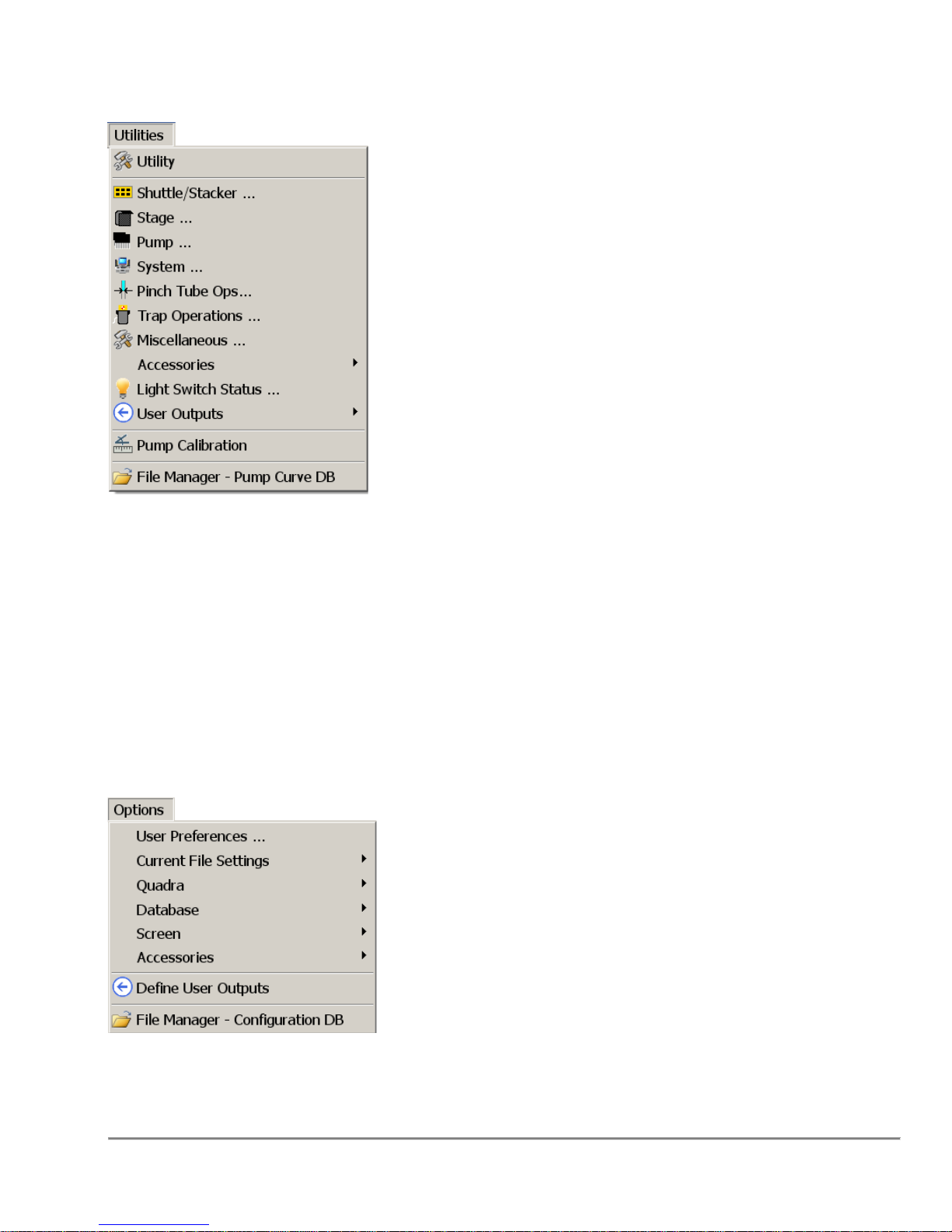
2.6.6 Utilities Menu
Most of these menu items open a specific Utility Dialog. These Utility Dialogs are
discussed in the Section “6.0 Utility” on page 111.
User Outputs – Refer to Section “5.6 Set User Defined Output Names” on Page 105.
Pump Calibration - Refer to Section “6.10 Pump Calibration Tables” on page 121.
File Manager – Pump Curve DB – Refer to Section “10.3 File Management – Curve
Database” on Page 146.
2.6.7 Options Menu
User Preferences – Refer to Section “5.1 User Preferences” on page 99.
Quadra 4 Operator Manual
44
Tomtec
Page 45
Current File Settings – This sub-menu shows options available elsewhere on the
menubar.
Database – This sub-menu shows some of the options available on the “Database”
Menu.
Screen - Saves the current screen size and position.
Define User Outputs – Refer to Section “5.6 Set User Defined Output Names” On
Page 105
File Manager – Configuration DB – Refer to Section “10.2 File Management –
Configuration Database” On Page 145
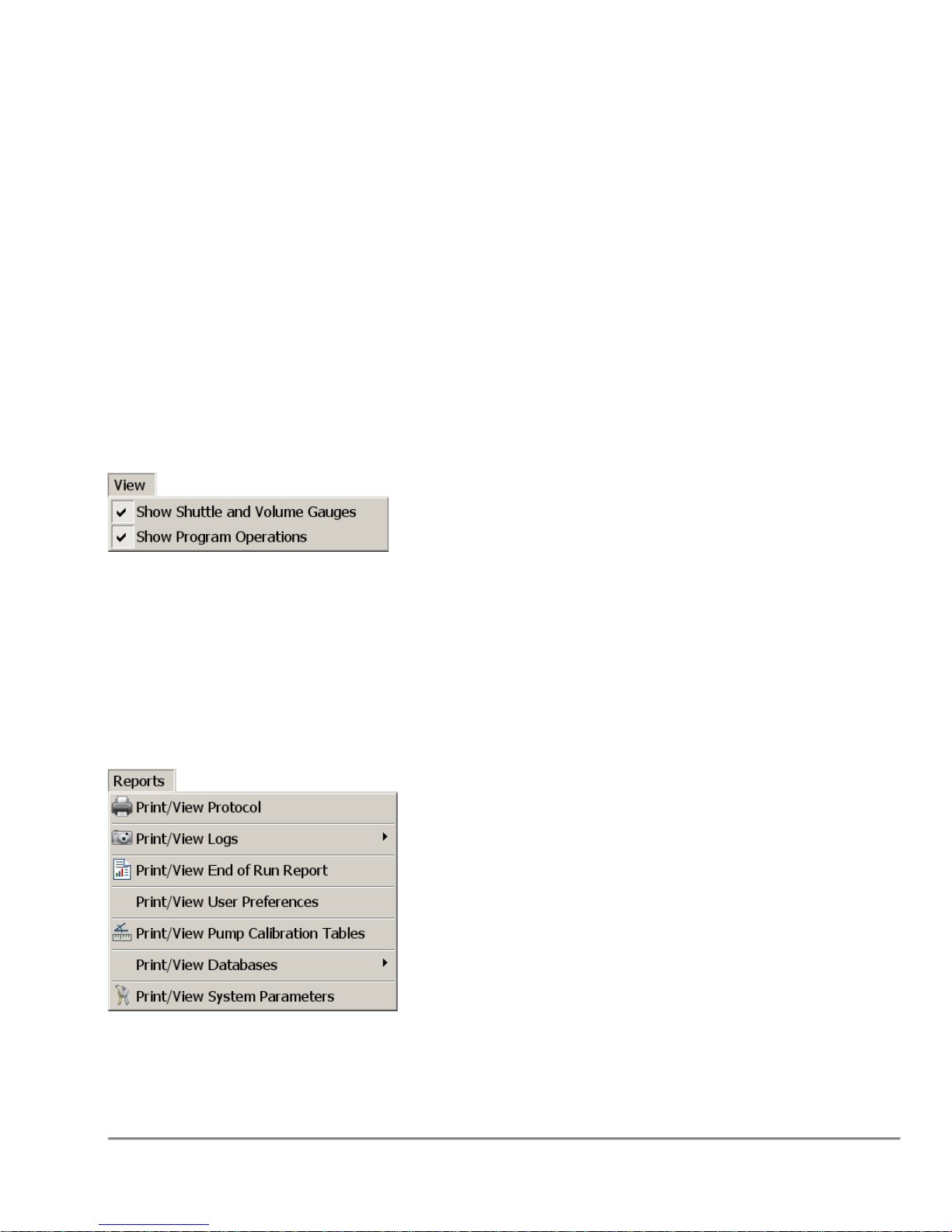
2.6.8 View Menu
Show Shuttle and Volume Gauges - When checked the top portion of the application
will be visible. The default is to show (checked).
Show Program Operations - When checked the Functions and Program will be visible.
The default is to show (checked).
2.6.9 Reports Menu
The "Reports" menu allows the user to view/print Programs, Logs, Databases, and
System Parameters.
Quadra 4 Operator Manual
45
Tomtec
Page 46
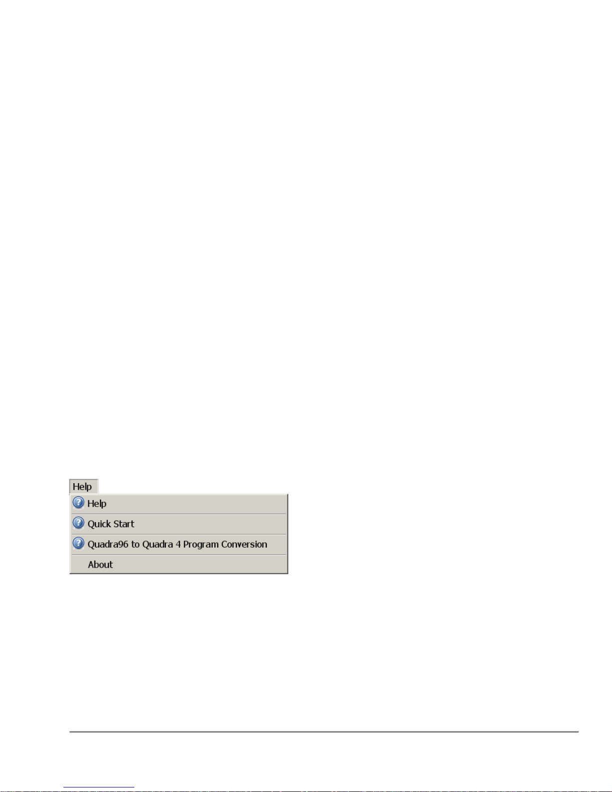
Print/View Protocol – Views the currently loaded protocol.
Print/View Logs – Views the Standard Log, and Barcode Logs.
Print/View End of Run Report - The "End of Run" report contains all information
needed to run the program. The Protocol with Sub Routines, Go To's, and Calibration
Tables, Run Time Log, Environmental Settings, and the System Parameters.
Print/View User Preferences – Views to current settings of all User Preferences.
Print/View Pump Calibration Tables – View the Pump Calibration tables.
Print/View Databases – View the Plate Database or Fixture Database.
Print/View System Parameters – Displays the current settings of all of the System
Parameters.
When viewing any of the above items, the following common controls are available:
Open File - The "Open File" allows the user to select a specific "End of Run Report" or
a System Parameter File. See File Manager for file descriptions.
Print To File - The "Print To File" saves the viewed report to an ascii text file.
Print - Prints the viewed report to either an attached printer or a network printer.
Printer Setup - The windows printer select/setup function is called.
2.6.10 Help Menu
Help - The "Help" menu brings up the Quadra's online help and product information.
The online help is the standard windows help engine.
Note: The online Help can be brought up at anytime by hitting the F1 key.
Quick Start - This invokes the Quadra 4's Quick Start Guide. Getting Started - Quick
Start Guide
Quadra 4 Operator Manual
46
Tomtec
Page 47
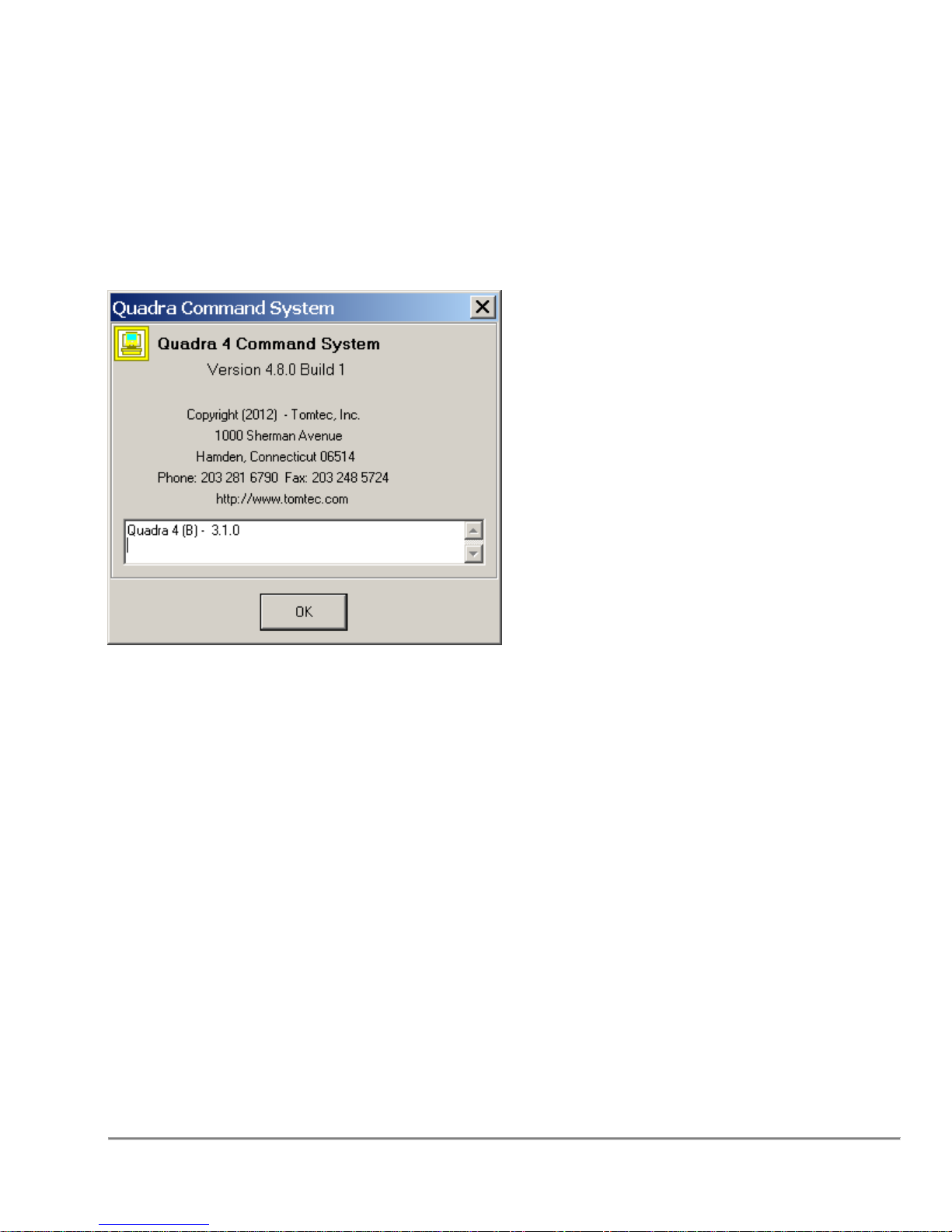
Quadra96 to Quadra 4 Program Conversion - This will guide you through the
procedure to convert a Quadra96 program to run on the Quadra 4.Quadra 96 to Quadra
4 Program Conversion
Tomtec FileSystem Watcher Service (21CFR Part 11 option) - This section will
appear if the optional software package has been installed and is running.
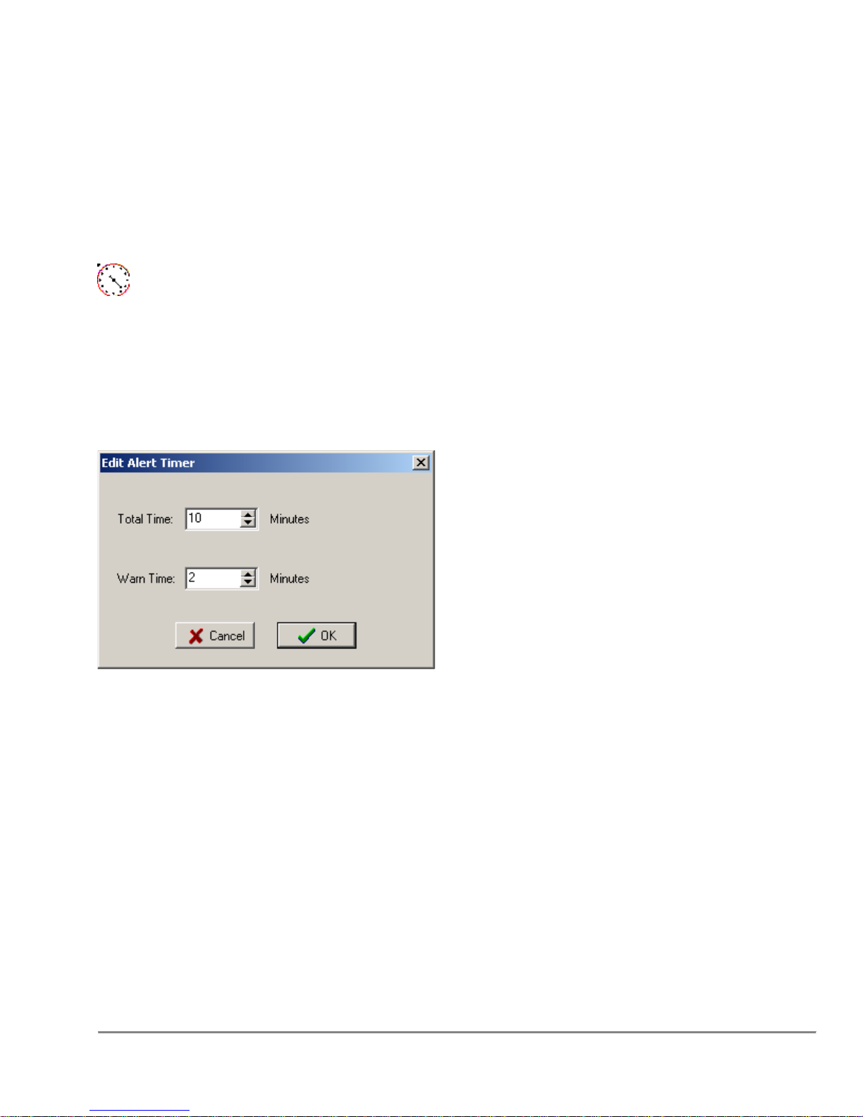
About – Displays information about the currently running Software and Hardware
versions, similar to this:
Note that the command system version and build number should be used whenever you
have to correspond with Tomtec.
Quadra 4 Operator Manual
47
Tomtec
Page 48
3.0 Program Operations
This section contains detailed information on all of the various program operations in
alphabetical order. Note: Based on the configuration of your Quadra, some of these
functions may not be available.
3.1 Alert Timer
The "Alert Timer" can be used to remind the operator of a task to be done.
Conditions
None
Remarks
Total Time
A minimum of one(1) minute to 1440 minutes(24 hours) can be programmed. If zero
time is issued, the current alert timer will be canceled.
Warn Time
Time remaining from the total time to issue a warning to the operator(0 to 10 minutes). If
zero(0) time is used, no warning will be issued.
The example above will alert the operator in 10 minutes, with warning issued with 2
minutes remaining.
When an alert is issued, the time will be posted on the shuttle image on the Main
Screen. This timer will count down, to show how much time is left before the Alert.
When the warning time is reached, the shuttle will turn RED, and the cancel alert button
will be displayed.
Quadra 4 Operator Manual
48
Tomtec
Page 49
When the time has expired the shuttle will flash.
Note that once the shuttle warns and alerts, the timer can be canceled by the cancel
button, or double clicking on the shuttle.
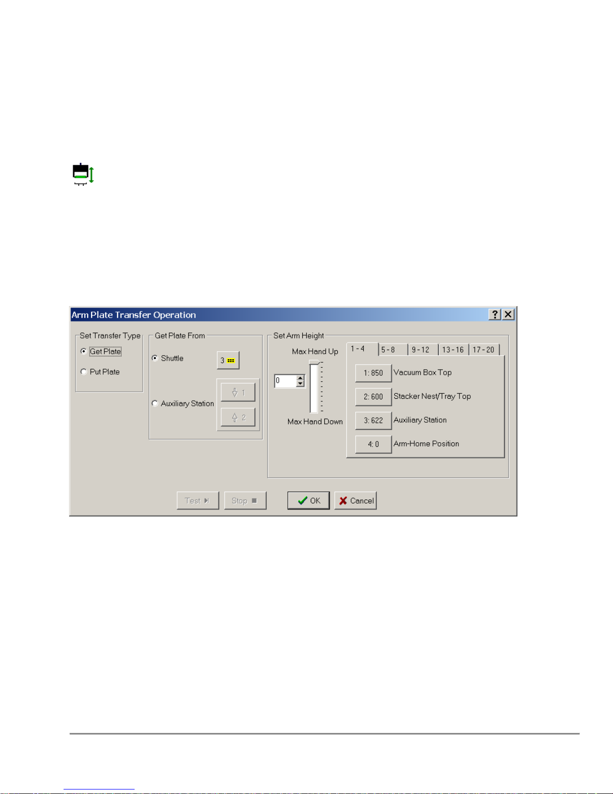
3.2 Arm Plate Transfer Operation
The arm plate transfer operation is used to get plates from and put plates to a stacker
nest, vacuum box, or auxiliary station.
Conditions
Requires a plate/reservoir nest Only shuttle positions 3 & 4 are valid for the Quadra 4
Remarks
Set Transfer Type
Indicates whether the hand is getting or putting the plate.
Get Plate From / Put Plate To
Indicates whether the plate is being transfer from/to the shuttle or auxiliary station.
Shuttle
Used to change the shuttle position that should move under the arm. The number on
the button indicates the currently selected position (see Select Shuttle Position ).
Quadra 4 Operator Manual
49
Tomtec
Page 50

Set Arm Height
Indicates the position to grab / release the plate. Preset positions are available
by clicking on the appropriate button. Preset buttons can be set under Options Accessories - Define Arm Positions (see Set Arm Position Names and Heights).
3.3 Aspirate Sample
To Aspirate is to pipette or draw from a designated plate or reservoir into the tips.
Conditions
To Aspirate, you will need to select a shuttle position that contains a plate or reservoir
capable fixture.
Remarks
Basic Settings
Aspirate Volume
Aspirate Volume is simply the amount of liquid (in µL) that is drawn into the tips.
This is the amount of liquid that you will want to Dispense in your plate(s).
Aspirate Speed
The Aspirate Speed is the rate at which the tips will pipette the liquid. This can be
a value between 1 and 4, 4 being the fastest. By default, 3 is automatically
selected.
Aspirate Height
This indicates whether the Aspirate height should be set to its default location
near the Bottom of the well, or if another value has been set.
Quadra 4 Operator Manual
50
Tomtec
Page 51

Advanced Settings
Air Gap Volume
The amount of air (in µL) that is aspirated in the tips before any liquid is
aspirated. This allows you to blowout any residue at the end of your dispense in
order to have the least amount of error when calculating the amount of liquid
actually dispensed into your plate.
The Air Gap is taken at the height set by the Clear Top Steps in your
plate database. The height of the blowout is set in the Dispense Dialog
when you insert a Dispense Step, and is NOT a result of the Clear Top Steps
value.
Note: Air Gap Volume becomes the Blow Out Volume when Dispense occurs.
Calibration Table
The Calibration Table drop down menu consists of user defined pump data for
the liquid type used. See documentation on distribution CD.
Additionally,refer to Section”3.37 Program Operations Common Options” on page 89
for information on other parameters used by this function.
Quadra 4 Operator Manual
51
Tomtec
Page 52
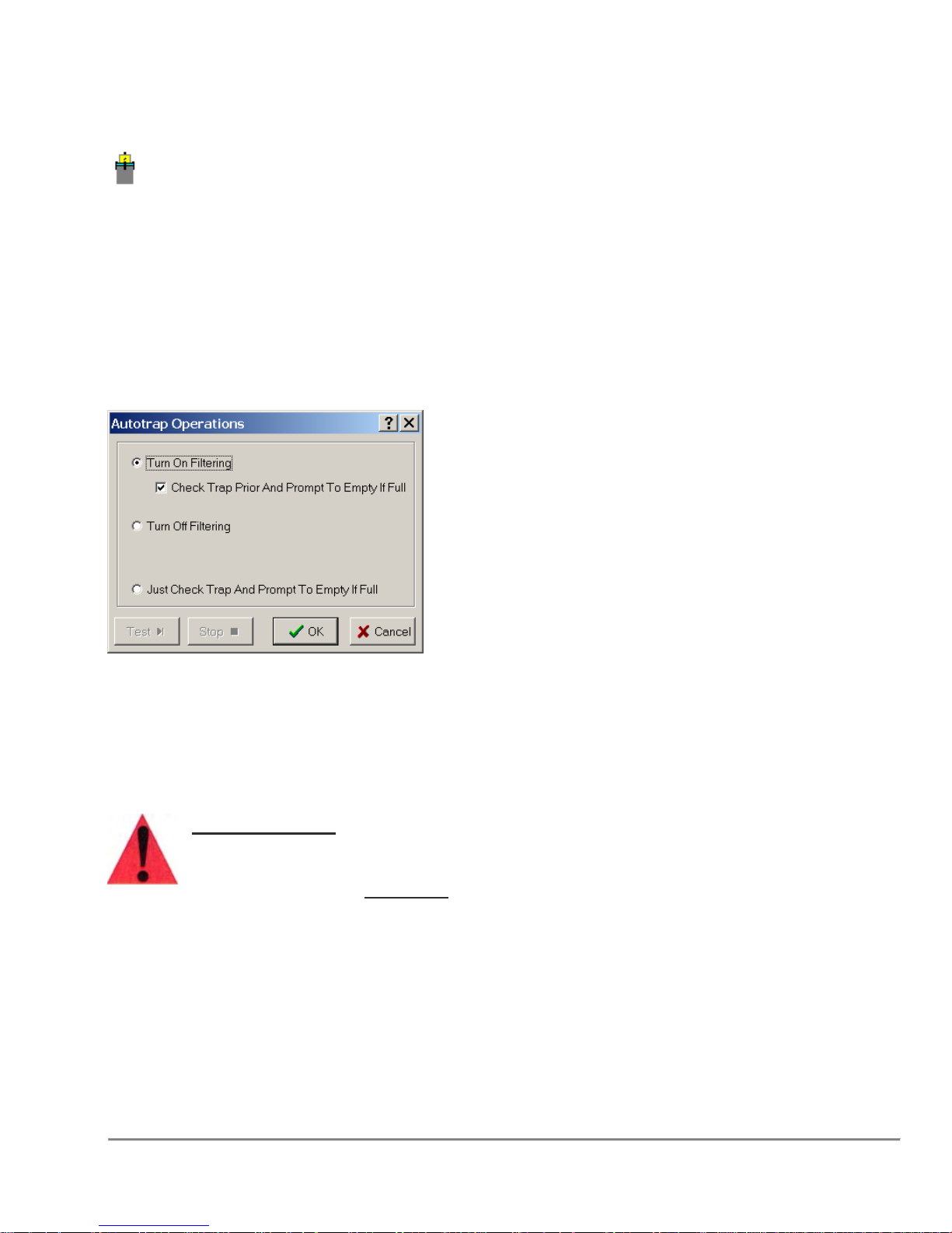
3.4 AutoTrap Operations
This operation provides control for the AutoTrap.
Conditions
None
Remarks
Turn On Filtering and Turn Off Filtering starts and stops plate filtering through a
vacuum box attached to the AutoTrap.
Check Trap and Prompt will perform a check of the liquid level in the trap. If it is full,
the program will pause and the user will be prompted to empty.
Important Note:
Powered accessories such as Vacuum Traps, Autotraps, and Shaker
Nests, should not be connected with the Quadra 4 powered on. Please
turn off AC
power
BEFORE
connecting these accessories.
Quadra 4 Operator Manual
52
Tomtec
Page 53
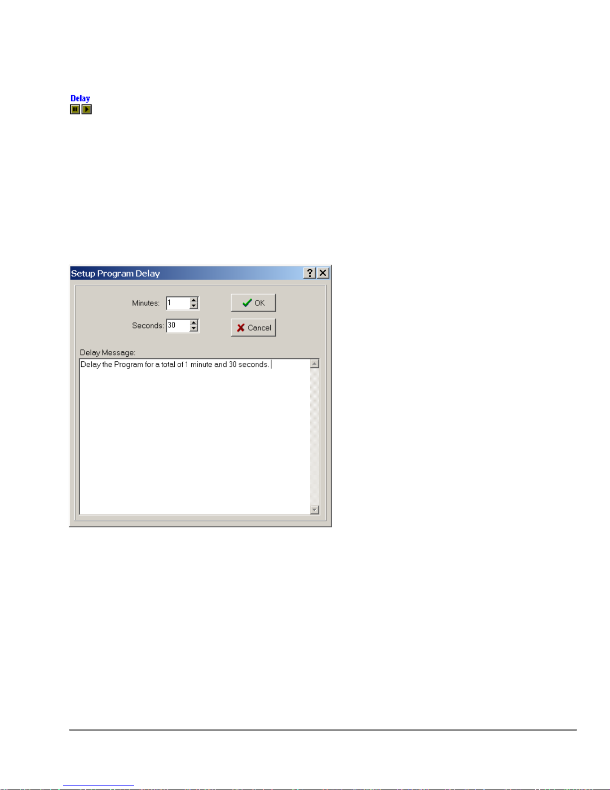
3.5 Delay Program
Pause the program for a specified period of time, designated in minutes and seconds,
without the need for user intervention.
Conditions
There are no requirements for this step to occur.
Remarks
Minutes
Designate the number of minutes the program is suppose to wait, in conjunction with
the number of seconds specified, before program continues.
Seconds
Designate the number of seconds the program is suppose to wait, in conjunction with
the number of minutes specified, before the program continues.
Quadra 4 Operator Manual
53
Tomtec
Page 54
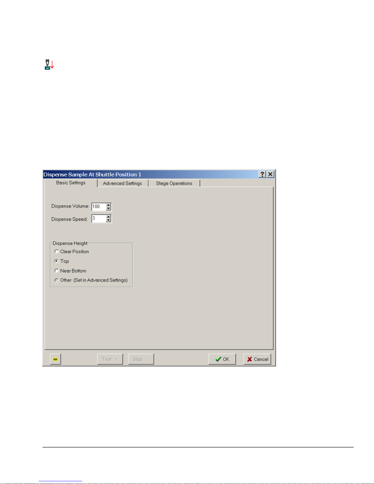
3.6 Dispense Sample
To Dispense is to pipette a liquid from the tips to a designated plate or reservoir.
Conditions
To Dispense, you will need to select a shuttle position. In order for the status
of the tip head to operate correctly, an Aspirate Step will have to be present before
a Dispense Step.
Remarks
Basic Settings
Dispense Volume
The amount of liquid (in µL) that is to be pipetted into the target plate or reservoir.
Quadra 4 Operator Manual
54
Tomtec
Page 55

Dispense Speed
The Dispense Speed is the rate at which the tips will pipette liquid. This can be a
value between 1 and 4, 4 being the fastest. By default, 3 is automatically
selected.
Dispense Height
Dispense Height is the height at which the tips will dispense from within the well.
This allows you to dispense at the appropriate height to wells without creating air
pockets within the wells.
Selecting “Clear Position”, “Top”, or “Near Bottom” will use the height values set
within the database for the plate being used. If a different value is required, this
can be set in the “Advanced Settings”.
Advanced Settings
Calibration Table
The Calibration Table drop down menu consists of user defined pump data for
the liquid type used. See documentation on distribution CD.
Blow Out Volume
Blow Out Volume is simply the amount of air (in µL) at the end of your Dispense
Step in order to flush the tips of all remaining liquid.
Blow Out Height
Blow Out Height is the height at which the tips will blow out the remaining
substance from within the well.
Touch Off
While Dispensing liquid into the plates, due to the surface tension at the tip
orifice, drops may form and remain on the tips when dispensing has concluded.
To accurately pipette the correct amount of liquid into the wells, these drops must
be captured. Using the ‘Touch Off’ is one method of capturing hanging
drops remaining on the tips. By setting the correct values within the Plate
Database, you can have the tips contact the side of the wells in order to release
the drops into the wells.
The Touch Off will occur at the height at which the Dispense or Blow Out has
ended. For example, if Liquid Following has been enabled, the Touch Off will
occur at the height at which the stage has come to a rest, otherwise it
will occur at the height specified by the ‘Dispense Height’ value.
Dip Tips
Dip Tips is another method of capturing hanging drops. Dip Tips is a
vertical Touch Off. What this function accomplishes is capturing drops held
on the tips by placing the tips in very close proximity to the liquid that has already
been dispensed into the wells.
Quadra 4 Operator Manual
55
Tomtec
Page 56
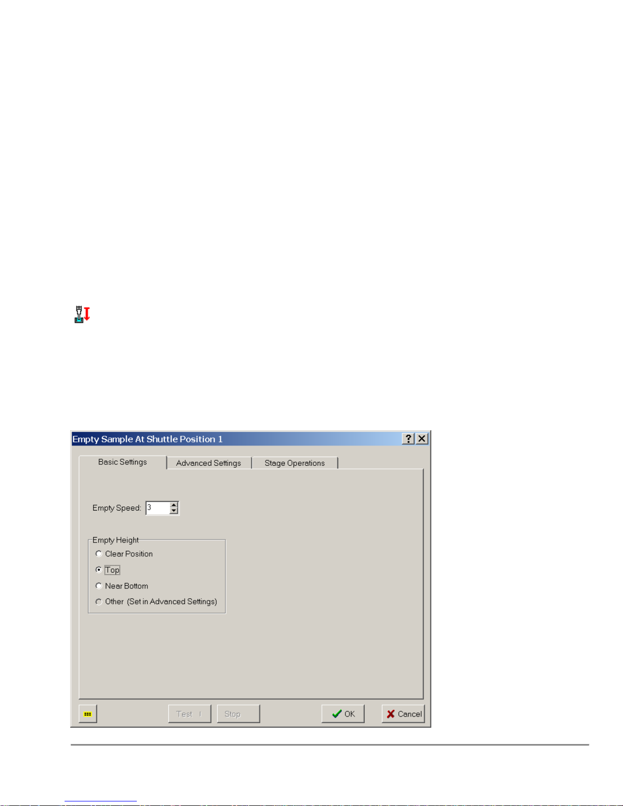
The ‘Dispense Tip Dip’ Value, by default, cannot exceed (be less than)
the Dispense Height. This is to prevent the Dip Tip function from never
reaching the liquid.
If Liquid Following is enabled, however, the restraint on the Dispense Tip Dip
value is lifted, due to the fact that the ending height after the Dispense Function
has been completed may be higher than the Dispense Height Value, or
the height at which the Dispense Function actually began. It is up to the user
from this point to estimate approximately how far within the well the liquid will
begin after the Dispense function has completed.
Additionally, refer to Section “3.37 Program Operations Common Options” on page 89
for information on other parameters used by this function.
3.7 Empty Sample
To dispense all liquid from tips completely.
Conditions
To Empty Sample, you will need to select a shuttle position that contains a plate or
reservoir capable fixture.
Remarks
Quadra 4 Operator Manual
56
Tomtec
Page 57

Basic Settings
Empty Speed
The Empty Speed is the rate at which the tips will pipette liquid. This can be a
value between 1 and 4, 4 being the fastest. By default, 3 is automatically
selected.
Empty Height
Empty Sample height is the height at which the tips will dispense liquid into the
well.
Selecting “Clear Position”, “Top”, or “Near Bottom” will use the height values set
within the database for the plate being used. If a different value is required, this
can be set in the “Advanced Settings”.
Advanced Settings
Touch Off
While Dispensing liquid into the plates, due to the surface tension at the tip
orifice, drops may form and remain on the tips when dispensing has concluded.
To accurately pipette the correct amount of liquid into the wells, these drops must
be captured. Using the ‘Touch Off’ is one method of capturing hanging
drops remaining on the tips. By setting the correct values within the Plate
Database,
you can have the tips contact the side of the wells in order to release the drops
into the wells.
The Touch Off will occur at the height at which the Dispense or Blow Out has
ended. For example, if Liquid Following has been enabled, the Touch Off will
occur at the height at which the stage has come to a rest, otherwise it
will occur at the height specified by the ‘Dispense Height’ value.
Dip Tips
Dip Tips is another method of capturing hanging drops. Dip Tips is a
vertical Touch Off. What this function accomplishes is capturing drops held
on the tips by placing the tips in very close proximity to the liquid that has already
been dispensed into the wells.
The ‘Dispense Tip Dip’ Value, by default, cannot exceed (be less than)
the Dispense Height. This is to prevent the Dip Tip function from never
reaching the liquid. If Liquid Following is enabled, however, the restraint on the
Dispense Tip Dip value is lifted, due to the fact that the ending height after the
Dispense Function has been completed may be higher than the Dispense
Height Value, or the height at which the Dispense Function actually began. It
is up to the user from this point to estimate approximately how far within the well
the liquid will begin after the Dispense function has completed.
Additionally, refer to Section “3.37 Program Operations Common Options” on page 89
for information on other parameters used by this function.
Quadra 4 Operator Manual
57
Tomtec
Page 58
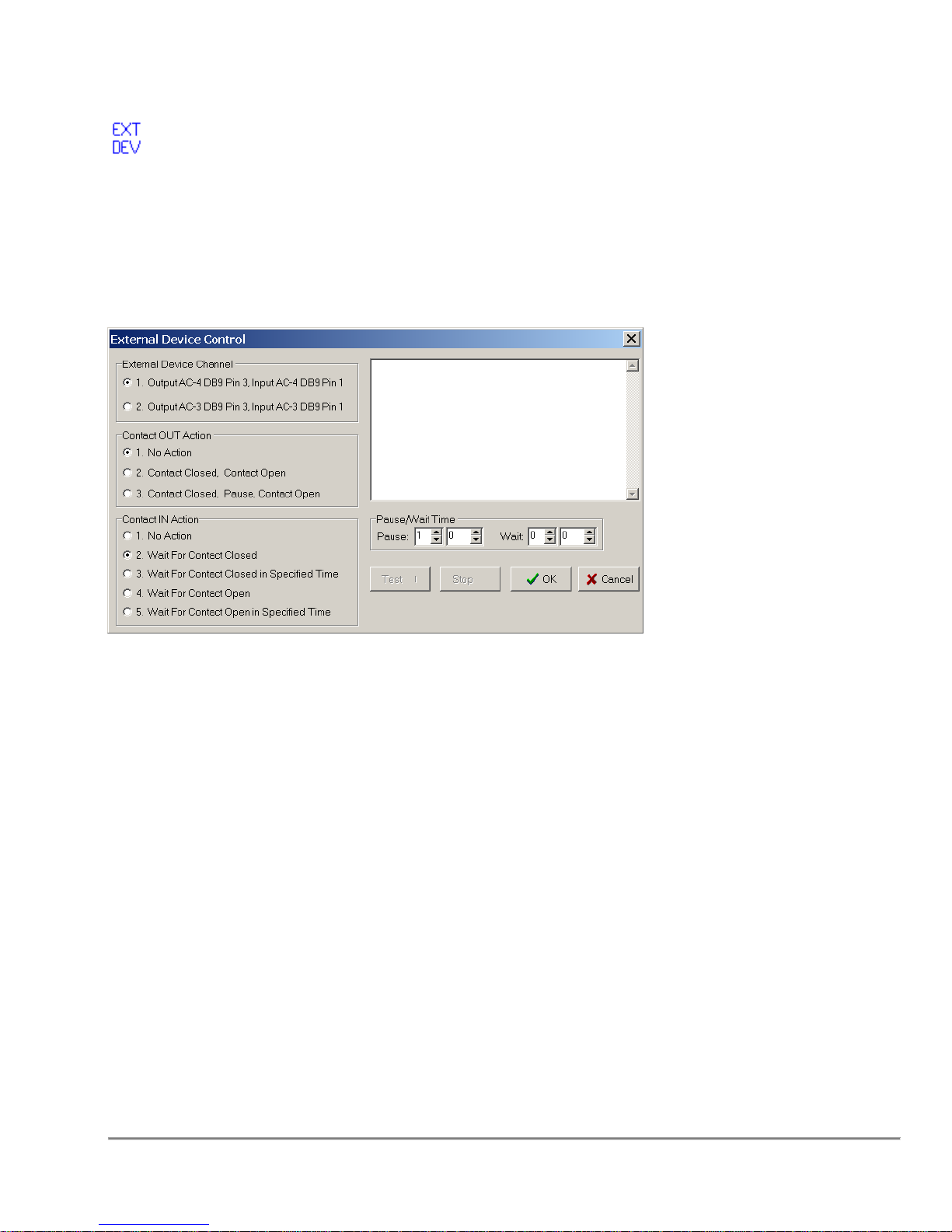
3.8 External Device
This function utilizes AC-3's & AC-4's I/O to control or monitor an external device.
Conditions
There are no requirements to run this step.
Remarks
External Device Channel
The Quadra 4 has two dedicated external control channels. Quadra 4 User
Defined Outputs
Contact OUT Action
The user can select to do nothing, No Action, toggle the contact, Contact Closed,
Contact Open, or toggle the contact with a timed pause, Contact Closed, Pause,
Contact Open.
Contact IN Action
The user can select to do nothing, No Action, wait for a contact to close, wait for
a specified time for the contact to close, wait for the contact to open, or wait for a
specified time for the contact to open.
Pause/Wait Time
Pause time is used for the Contact Out, Wait time for the Contact In. Both timers
have a 90 minute, 3600 second maximums.
A message can also be displayed if the Contact Out/Contact In times are greater
than 6 seconds.
.
Quadra 4 Operator Manual
58
Tomtec
Page 59
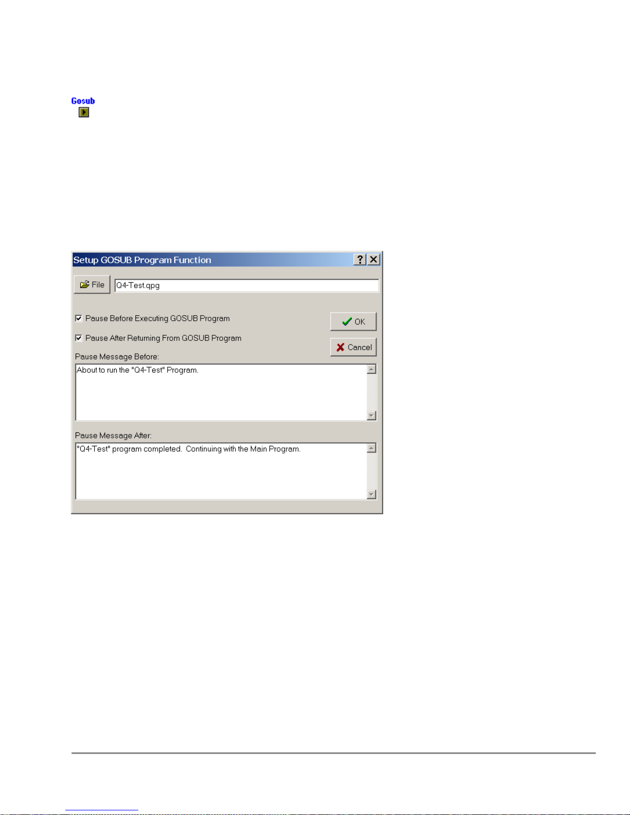
3.9 GOSUB Program
Calls a different program at that point, which will run from start to finish, and then return
to the original program, and finish the remaining steps
Conditions
There are no physical requirements to run this step.
Remarks
File Button
The File Button calls an Open File Dialog box, which allows the user to select another
program, and will automatically insert the full path name into the appropriate edit box.
Pause Before Executing GOSUB Program
By checking Pause, the program will stop and wait for user intervention when the
program reaches this step, but before it runs. A Text box will appear after the Pause
function is selected, giving the user an opportunity to generate a message to be
displayed when the program pauses.
Pause After Returning From GOSUB Program
By checking Pause, the program will stop and wait for user intervention when the
selected program completes but before the Main Program continues. A Text box will
appear after the Pause function is selected, giving the user an opportunity to generate a
message to be displayed when the program pauses
Quadra 4 Operator Manual
59
Tomtec
Page 60
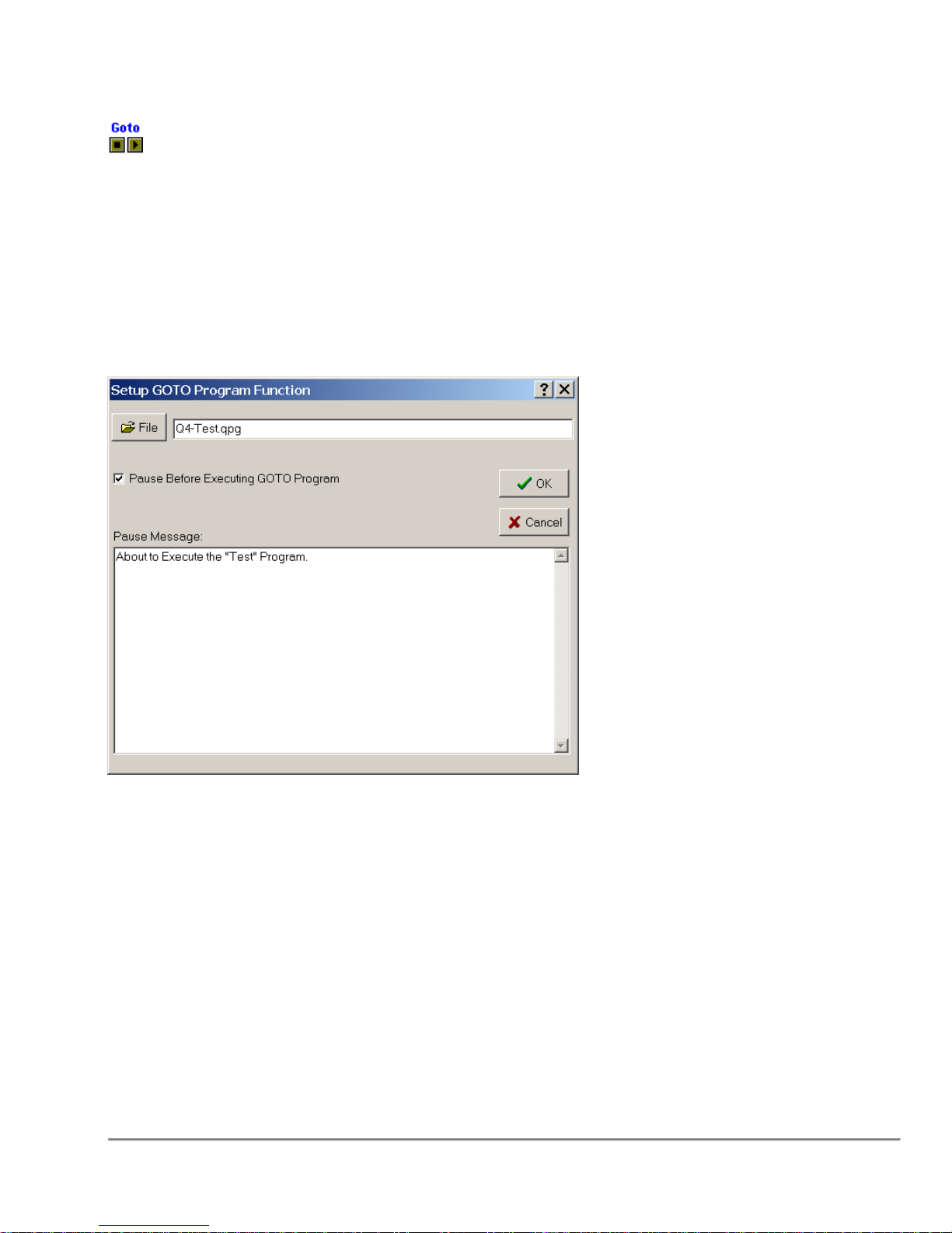
3.10 GOTO Program
Calls a different program, which it will run from start to finish, and then stop.
Conditions
There are no physical requirements for this step.
Remarks
File Button
The File Button calls the Open File Dialog box, which allows the user to select another
program, and will automatically insert the full path name into the appropriate edit box.
Pause Before Executing GOTO Program
By checking Pause, the program will stop and wait for user intervention when the
program reaches this step, but before it runs. A Text box will appear after the Pause
function is selected, giving the user an opportunity to generate a message to be
displayed when the program pauses.
Quadra 4 Operator Manual
60
Tomtec
Page 61
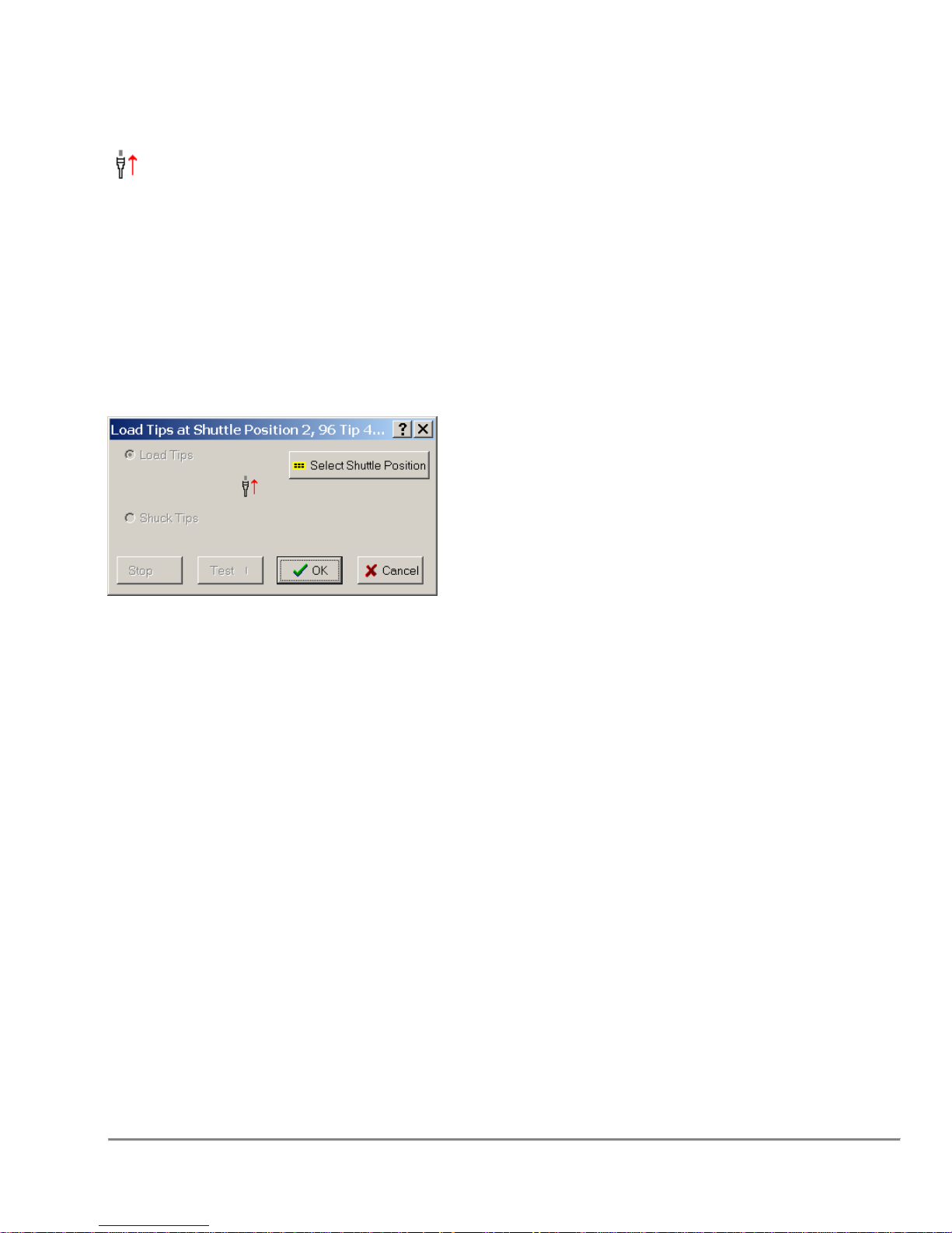
3.11 Load Tips
To Load Tips is to attach disposable tips to the tip pins, or attach a fixed tip assembly to
the tip head assembly.
Conditions
To Load Tips, select a shuttle position that has a tip capable fixture.
Remarks
Load Tips
Sets the function to load tips from the selected shuttle position.
Pre-Wet Tips (DSV Head Only)
Sets indicator to pre-wet tips on next Aspirate step. Pre-wet will not be
performed until start of Aspirate function. Indicator will persist between user
program runs. This options is only available for certain pumps.
The Load Tips function can also be used to Load an SPE Pressure block if there is an
SPE Block at the specified shuttle position. In this case “Load Tips” will be replaced by
“Load SPE”.
Note: On models equipped with the DMV head, the tip volume is set by the selected tip
fixture. That is if a 50ul tip fixture is selected, all liquid handling functions after the tip
load will set their maximum volume to 50ul. The firmware will set its maximum volume
to 50ul. This is done to prevent any pump range errors.
Quadra 4 Operator Manual
61
Tomtec
Page 62
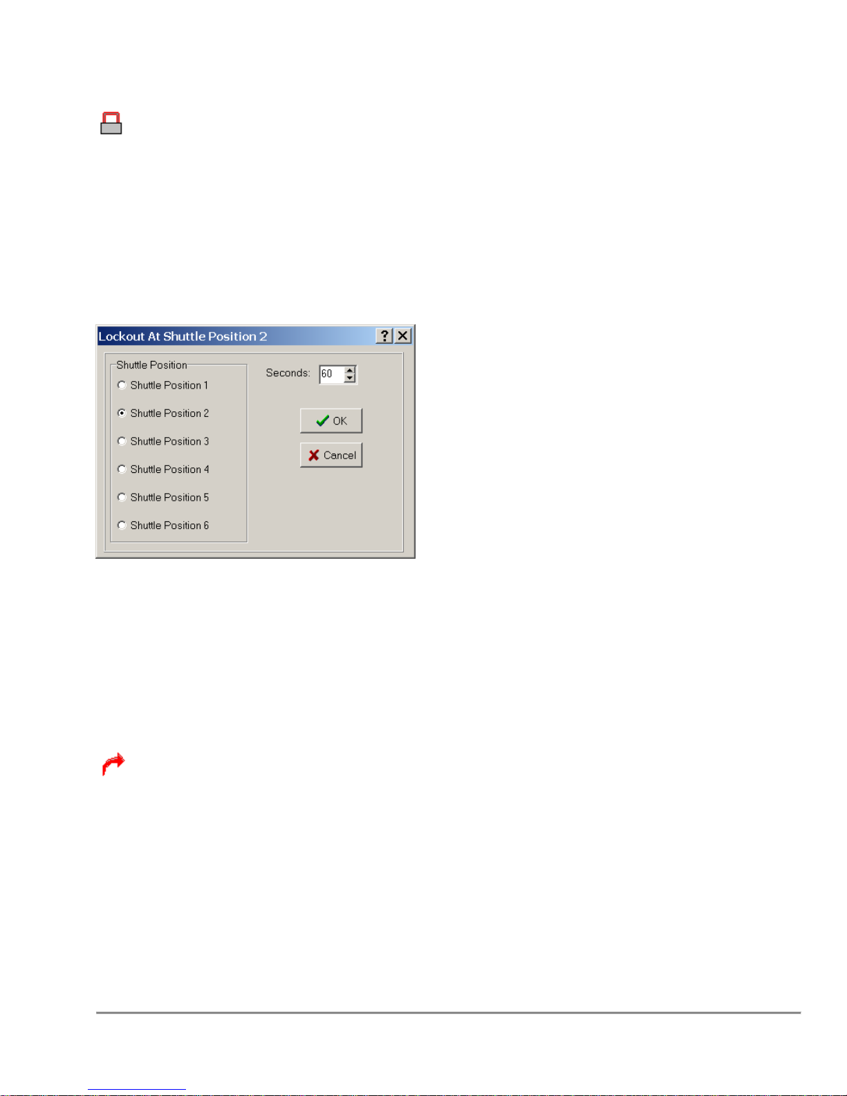
3.12 Lockout Shuttle Position
Lockout Shuttle Position will prevent any pipetting function from occurring at that
position for a specified period of time.
Conditions
There are no physical requirements for this function.
Remarks
Shuttle Position
Select the shuttle position number to lock.
Seconds
Designates the number of seconds to prevent operation on that position.
3.13 Loop
Enables the user to repeat a series of steps and allows the user the ability to perform
repetitive stacker functions.
Conditions
There are no requirements for this function.
Quadra 4 Operator Manual
62
Tomtec
Page 63
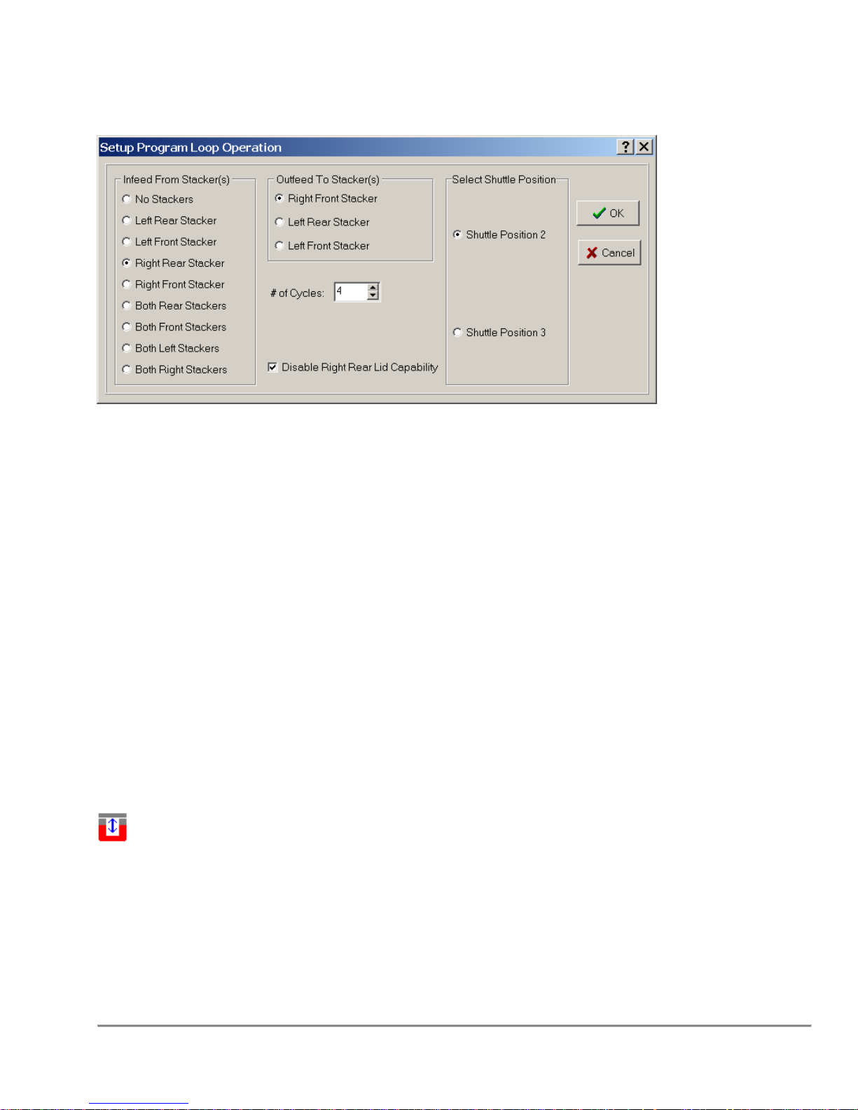
Remarks
Infeed From Stacker(s)
Selects stacker or stackers to infeed plates to the shuttle. For a simple Program loop,
set this value to “No Stackers”.
Outfeed To Stacker(s)
Selects stacker or stackers to outfeed plates from the shuttle.
Number Of Cycles
The number of cycles to run the enclosed steps.
Disable Lid Capability
Disable Lid Capability indicates that if the stacker supports lids than the plate
being processed does not have one. This is necessary for thin plates.
3.14 Magnetic Nest
A stacker accessible nest that can be fitted with a variety of magnet
configurations for 96 or 384 well plate processing of magnetic and paramagnetic
beads/particles. The magnetic surface or probes are moved by programming the
Quadra to deliver pressurized air to the nest bladder which raises the magnetic platform
Conditions
A Magnetic Nest has to be present on the selected shuttle position.
Quadra 4 Operator Manual
63
Tomtec
Page 64
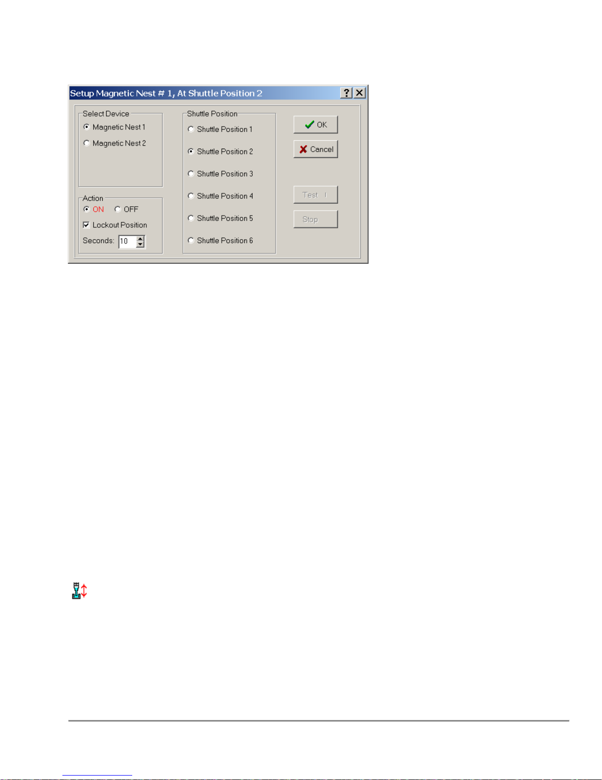
Remarks
Select Device
The Magnetic Nest can be connected to the Quadra in one of two places: Magnetic
Nest 1 is connected to the air terminal on the left side of the machine, while Magnetic
Nest 2 is connected to the right side of the machine.
Action
Turns the units On and Off.
Toggle Action
When selected, the value will appear in red to give quick visual identification of what this
function is to perform.
Lockout Position
Locks the position from use for the given amount of time, specified in seconds.
For more information, see "Lockout Shuttle Position."
Seconds
Number of seconds to lockout the shuttle position.
Shuttle Position
Click the appropriate radio button to select the shuttle position holding the Magnetic
Nest.
3.15 Mix Sample
Alternating aspirate and dispense steps to achieve a uniform suspension or
thorough mixing of chemicals, reagents, and/or buffers.
Conditions
To Mix, you will need to select a shuttle position that contains a plate or reservoir
capable fixture.
Quadra 4 Operator Manual
64
Tomtec
Page 65
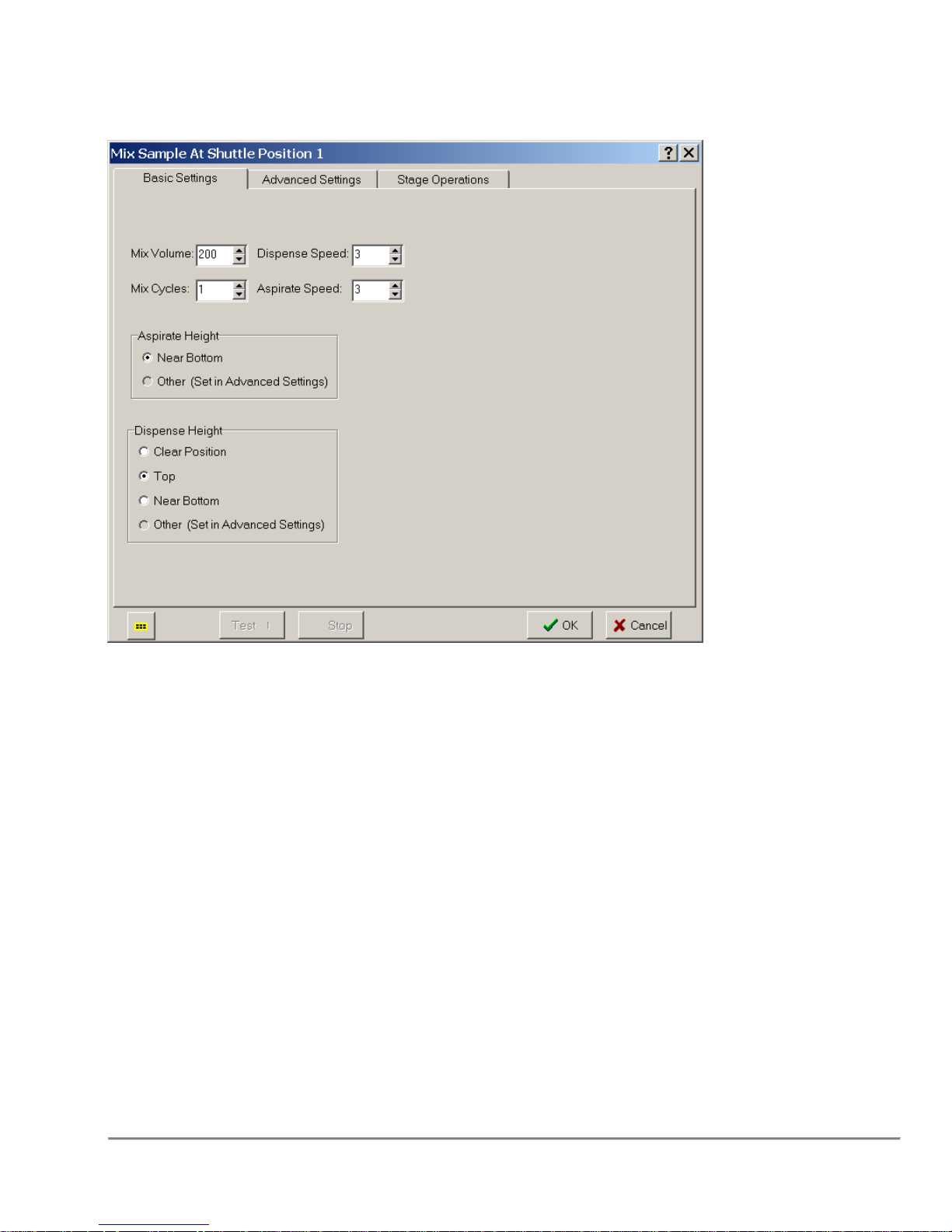
Remarks
Mix Cycles
Mix Cycles is the number of repetitions the mixing process will go through before
commencing this step.
Mix Volume
The Mix Volume is the amount of liquid (in µL) that is to be aspirated and
dispensed to the designated well for x number of cycles.
Air Gap/Blow Out
See Aspirate / Dispense Function.
Blow Out Height
See Dispense Function.
Touch Off
See Dispense Function.
Dip Tips
See Dispense Function.
Quadra 4 Operator Manual
65
Tomtec
Page 66
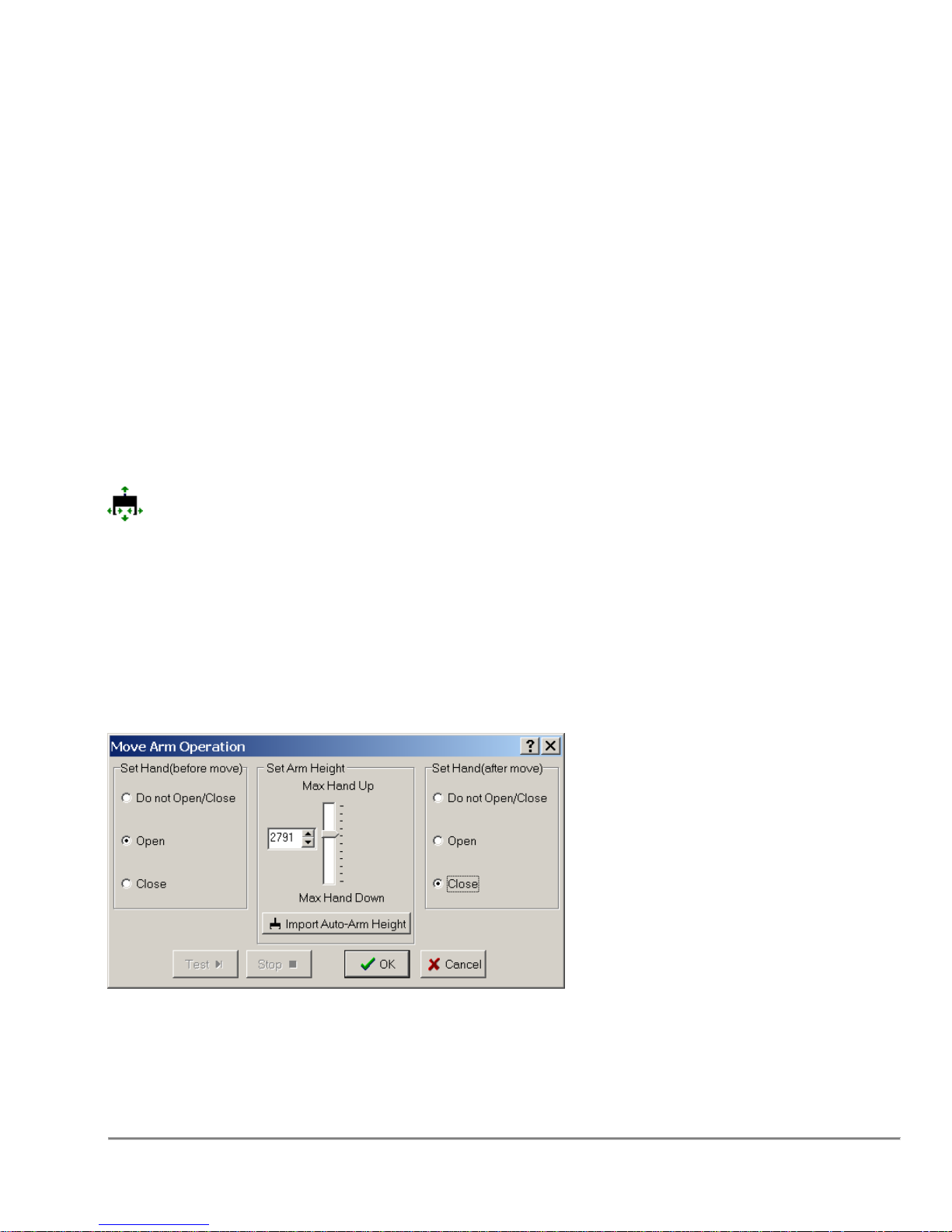
Aspirate Speed
See Aspirate Function.
Aspirate Height
See Aspirate Function.
Dispense Speed
See Dispense Function.
Dispense Height
See Dispense Function.
Additionally, refer to Section “3.37” Program Operations Common Options on page 89 for
information on other parameters used by this function.
3.16 Move Arm
The move arm operation is used to change the position of the device as well as open /
close the hand.
Conditions
None
Remarks
Set Hand (before move)
Indicates the state of the hand before and during the move.
Quadra 4 Operator Manual
66
Tomtec
Page 67
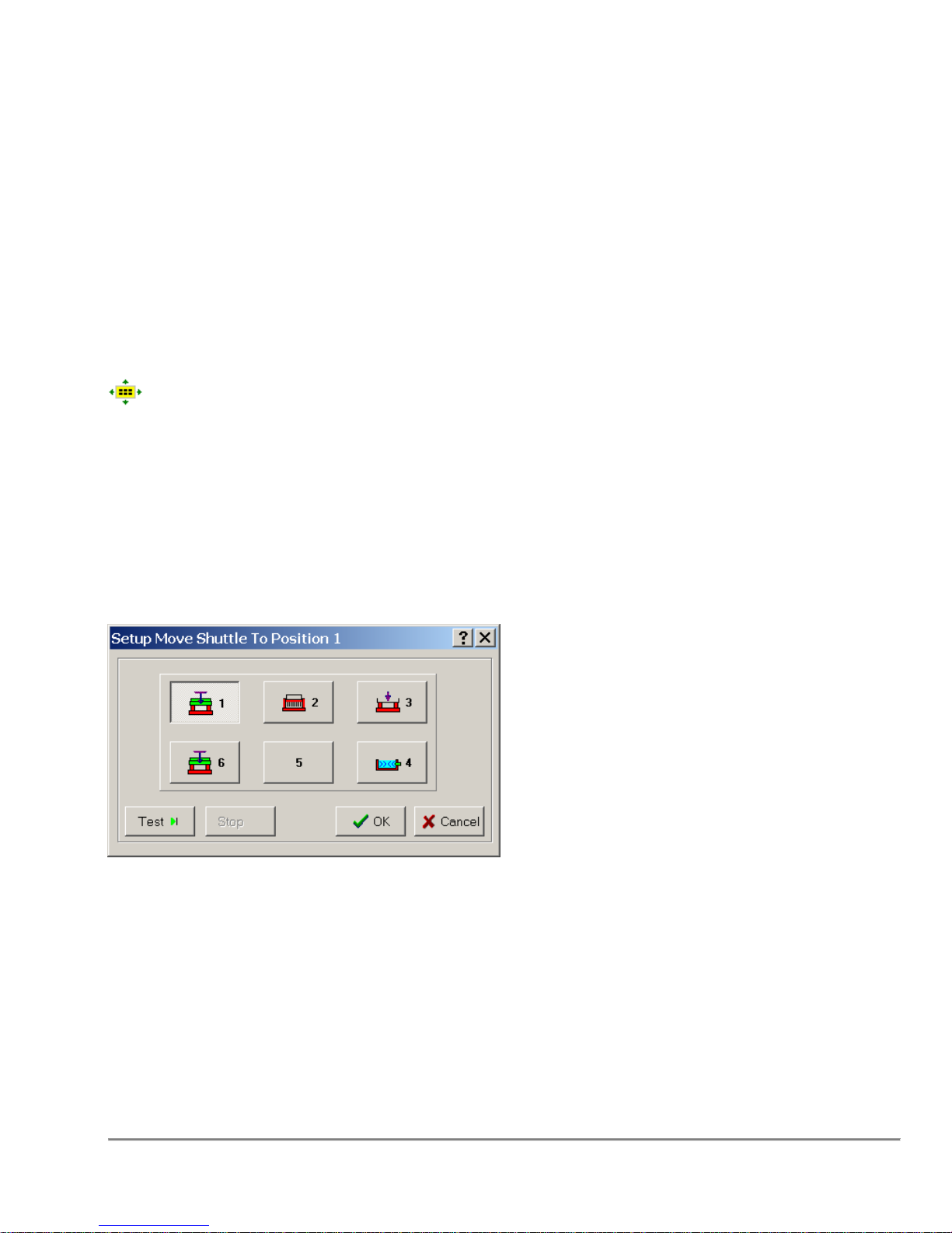
Set Arm Height
The absolute position for the arm to move to.
Import Auto-Arm Height
Fetches the user pre-defined arm heights.
Set Hand (after move)
Indicates the state of the hand after it moves.
3.17 Move Shuttle
Allows a simple move of the shuttle to any position.
Conditions
There are no physical requirements for this function.
Remarks
Shuttle Position
Select the shuttle position that will be moved. The position selected is positioned above
the stage.
Quadra 4 Operator Manual
67
Tomtec
Page 68
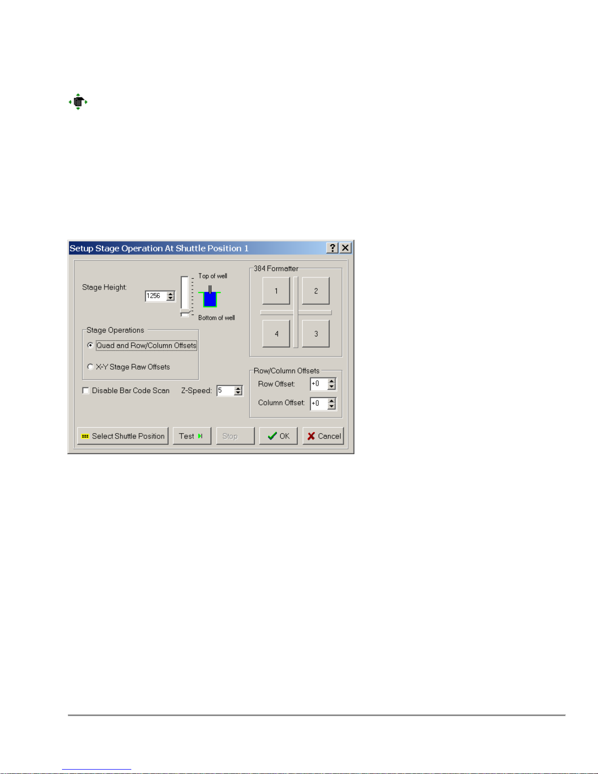
3.18 Move Stage
Moves the stage to the specified height and position.
Conditions
There are no requirements for this operation.
Remarks
Quadra 4 Operator Manual
68
Tomtec
Page 69
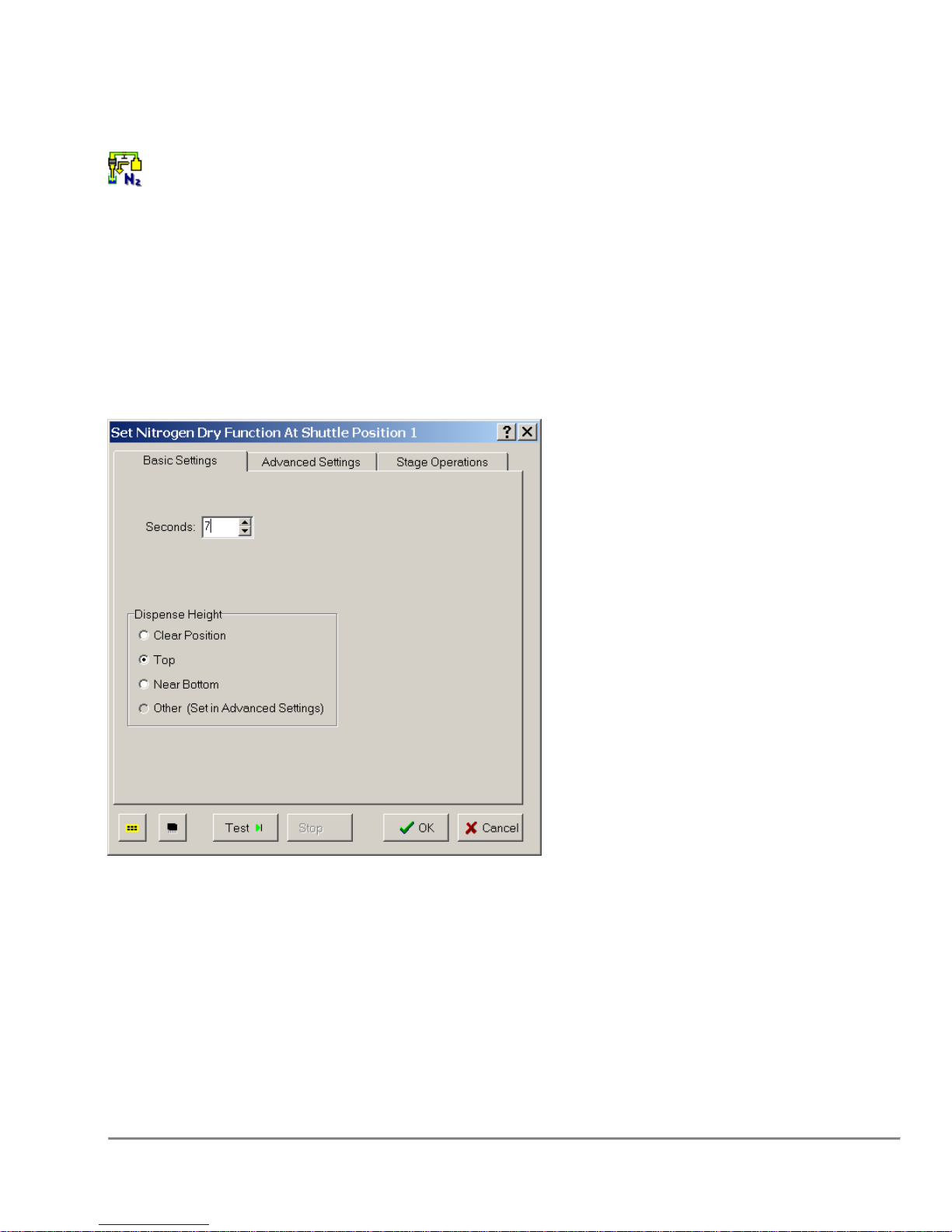
3.19 Nitrogen Dry
The Nitrogen Dry operation provides a means to blow nitrogen gas out the tips to
expedite sample drying.
Conditions
A 450µL backfill pump with the optional nitrogen gas valve installed is required.
Remarks
Seconds
indicates the amount of time for nitrogen gas to be blown out the tips.
Height
indicates the desired stage position to perform the operation.
Quadra 4 Operator Manual
69
Tomtec
Page 70
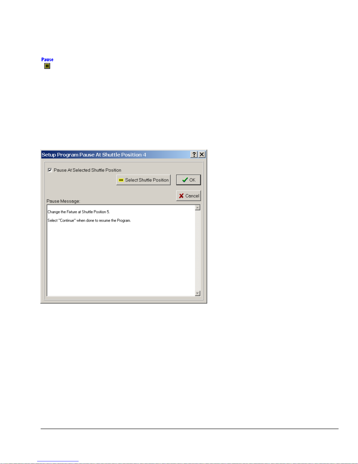
3.20 Pause
Stops the program and will not continue until the user intervenes.
Conditions
There are no physical requirements for this function.
Remarks
Shuttle Position
By selecting a shuttle position, the program pauses at the specified shuttle position and
waits for user intervention.
Message
In the Text Box below, the user has an opportunity to generate a message that
will appear on the screen when the system pauses.
Quadra 4 Operator Manual
70
Tomtec
Page 71
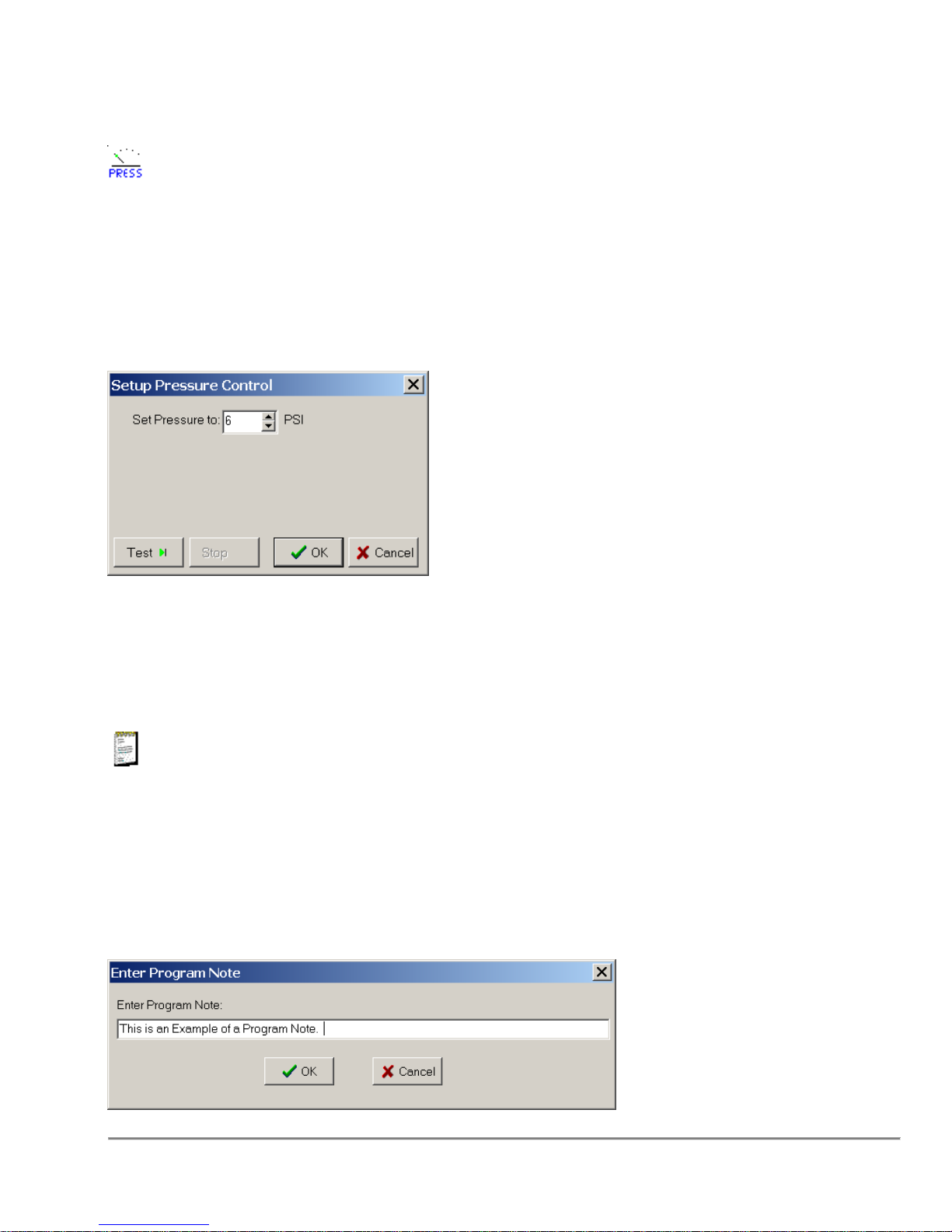
3.21 Pressure Control
This function is used to set the pressure.
Conditions
The controlled pressure regulator must be installed.
Remarks
Set Pressure
Sets the pressure regulator from 0 (off) to 15 PSI.
3.22 Program Note
This is a non-function. "Note" is a comment line added to the program for any reason.
Conditions
None
Remarks
Quadra 4 Operator Manual
71
Tomtec
Page 72
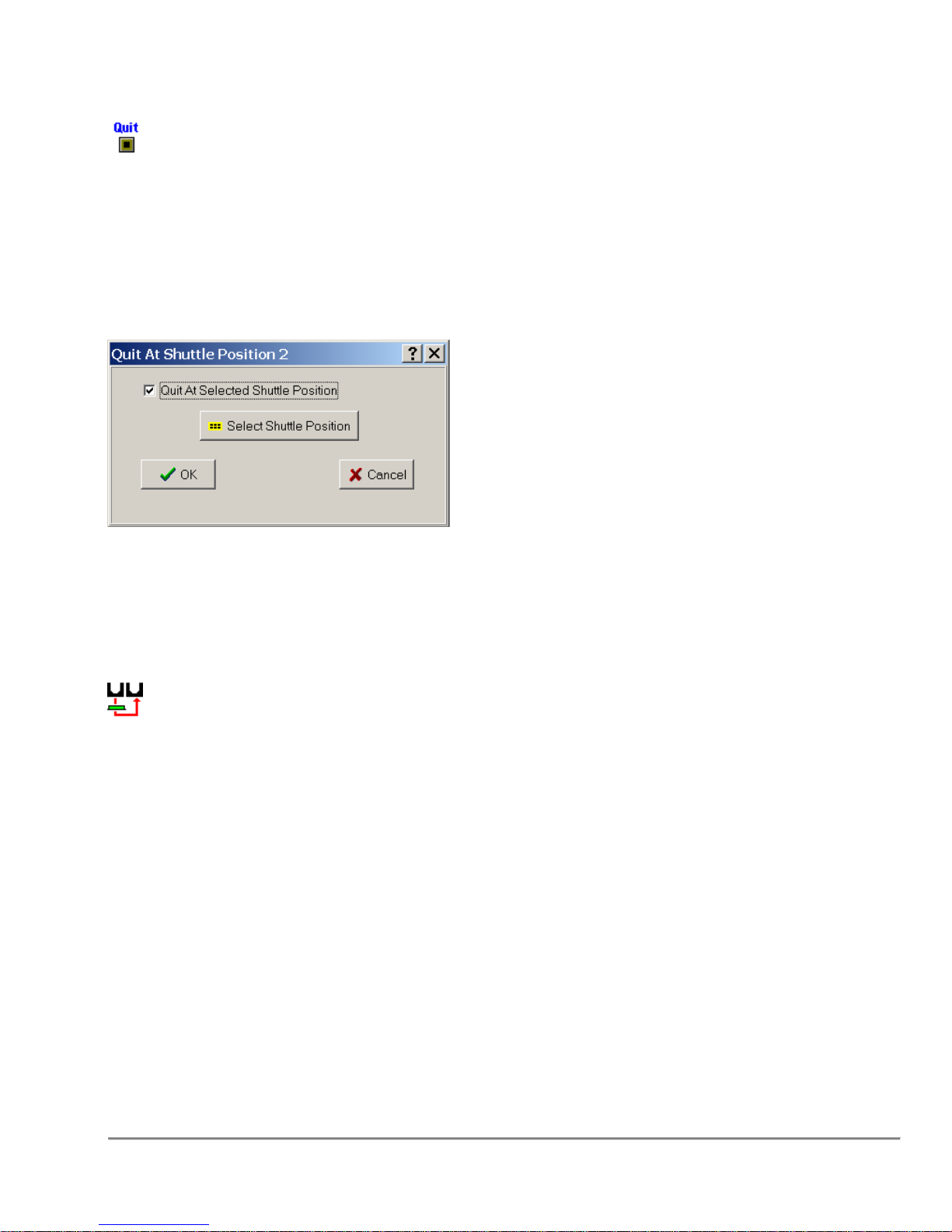
3.23 Quit
Stops the program and parks the shuttle at a specified position.
Conditions
There are no physical requirements for this function.
Remarks
Shuttle Position
Select the shuttle position you wish to stop the shuttle at the completion of the program.
3.24 Restack Plates
Restack Plates is the repeated Infeed of a plate from one stacker and Outfeed that plate
to another stacker.
Conditions
A plate capable fixture must be located on a shuttle position that has access to both the
source and destination stackers.
Remarks
Quadra 4 Operator Manual
72
Tomtec
Page 73
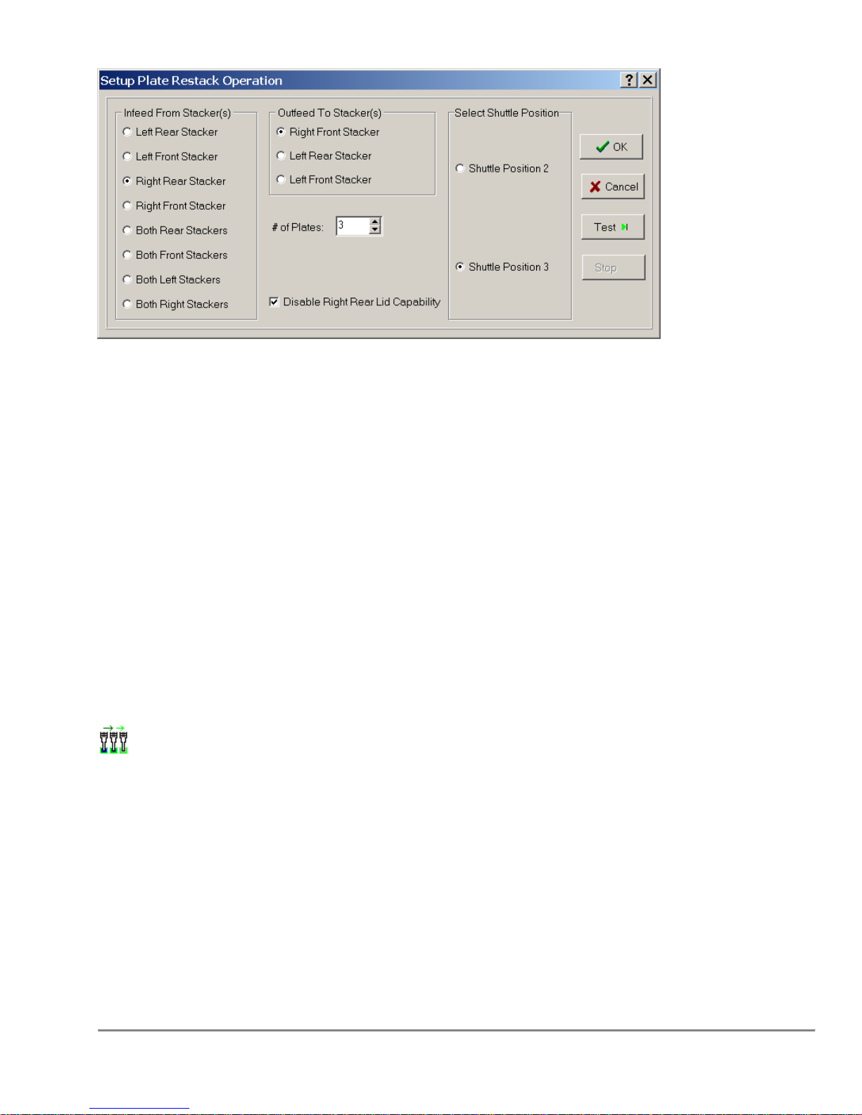
Infeed From Stacker(s)
Selects stacker or stackers to infeed plates to the shuttle.
Outfeed To Stacker(s)
Selects stacker or stackers to outfeed plates from the shuttle.
Number Of Plates
The number of plates to restack.
Disable Lid Capability
Disable Lid Capability indicates that if the stacker supports lids than the plate
being processed does not have one. This is necessary for thin plates.
3.25 Serial Dilution
A method of creating a numerical progression of concentrations along a series of
rows or columns by sequentially aspirating the same volume and transferring that
volume to the adjacent row or column a number of times.
Conditions
The Serial Dilution function requires a selected shuttle position.
Note: This function is only available when a removable tip pump is installed.
Quadra 4 Operator Manual
73
Tomtec
Page 74
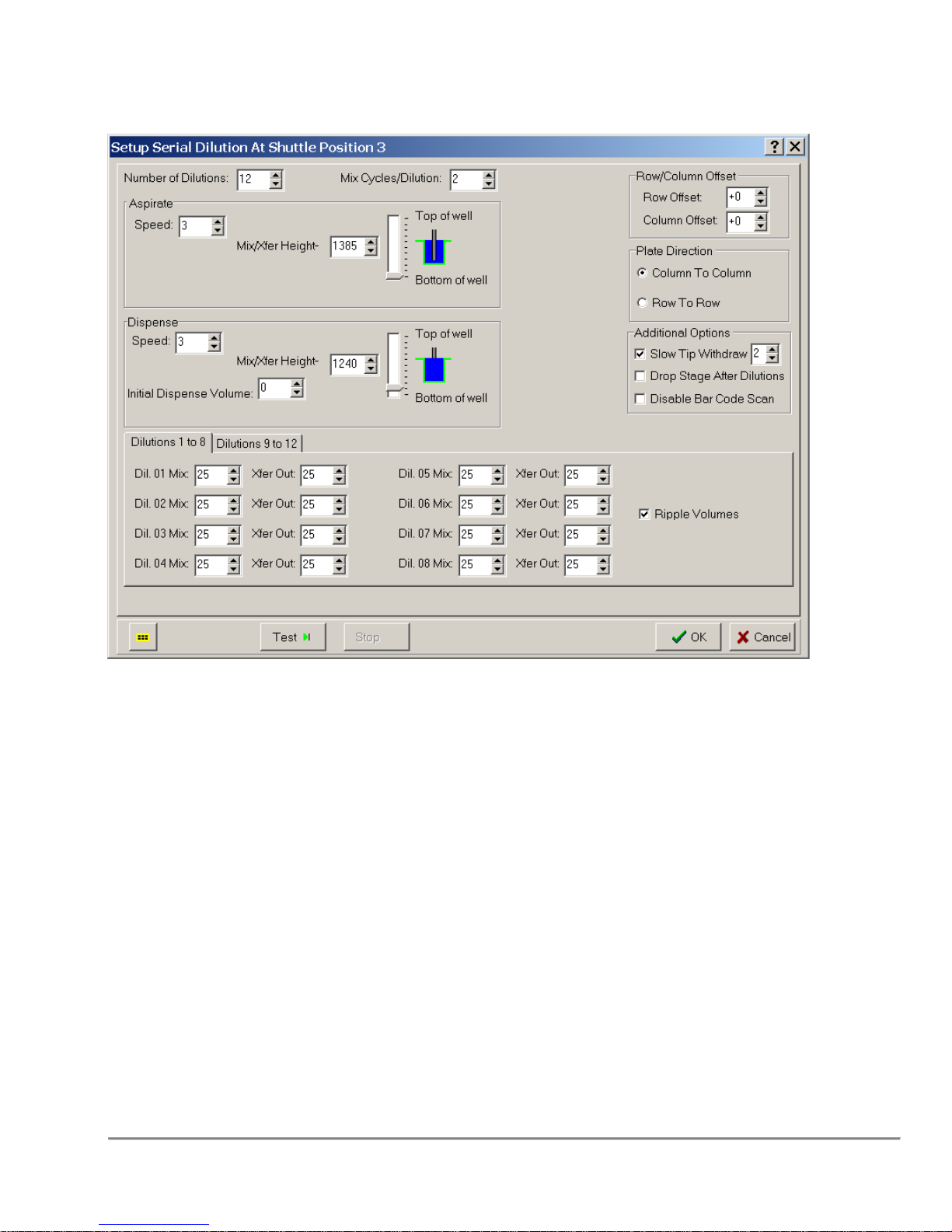
Remarks
Number of Dilutions
Depending on plate type and tip arrangement, the number of dilutions can range from 1
to 24.
Mix/Xfer Aspirate Height
Aspirate Height is the height at which the tips will aspirate from the well. This allows you
to aspirate from wells filled to a variable amount, without sucking in any air.
Mix/Xfer Dispense Height
Dispense Height is the height at which the tips will dispense into the well. This allows
you to dispense to wells filled to a variable amount, without creating air pockets within
the wells.
Initial Dispense Volume
The initial concentration pipetted from a sample plate.
Plate Direction
The direction in which the dilution is performed. This depends on the plate and
tip arrangement.
Quadra 4 Operator Manual
74
Tomtec
Page 75

Mix Cycles/Dilution
The number of mix cycles(0 to 99) per dilution. A zero(0) value will eliminate the mix
function.
Aspirate Speed
See Aspirate Speed in the Aspirate.
Dispense Speed
See Dispense Speed in the Dispense Function.
Row/Column Offset
The location for Dilution 1. All subsequent dilutions will follow left to right or top to
bottom of the plate, one row at a time. See Quad & Row/Column Offset in Stage
Operations for more details.
Ripple Volumes
This is a convenience when setting up the serial dilution to allow the same volume to
automatically be set for multiple successive dilutions. For example, if Ripple Volumes
is checked and I change Dil. 2 Mix volume, Dil. 3 Mix volume and down will
automatically be set to the same volume. Dil. 1 Mix Volume would be unaffected. Ripple
Volumes is a design time tool only. It has no bearing when the program is actually
running.
Dilution # Mix
The mix volume for each dilution performed.
Dilution # Xfer Out
The transfer volume from current dilution to the next. If a transfer out volume is specified
for the last dilution, that volume will be in the tips at the completion of the function.
3.26 Shaker Nest
A stacker accessible nest that has an electronic oscillating mechanism that can
be turned on and off programmatically in the Quadra. The oscillation amplitude is
controlled by a dial on the Shaker Nest.
Conditions
You must have a shaker nest on the specified shuttle position, properly connected to
the Quadra in order for this function to work.
Quadra 4 Operator Manual
75
Tomtec
Page 76
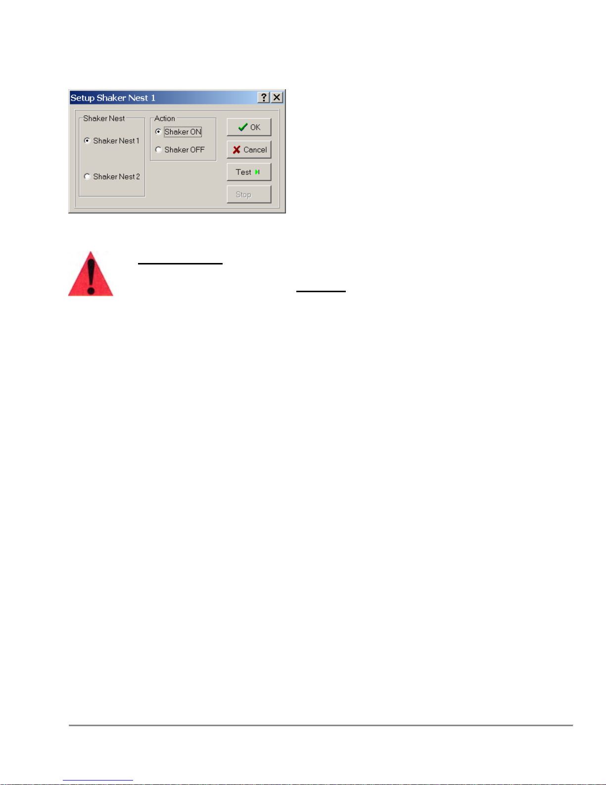
Remarks
Important Note: Powered accessories such as Vacuum Traps, Autotraps
and Shaker Nests, should not be connected with the Quadra 4 powered
on. Please turn off AC power BEFORE connecting these accessories.
Specify which shaker nest to control, and whether or not to switch the device on or off.
Quadra 4 Operator Manual
76
Tomtec
Page 77
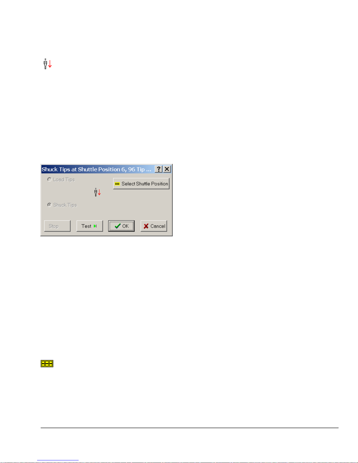
3.27 Shuck Tips
Shuck Tips removes disposable tips from the tip pins or removes fixed tip assembly
from the tip head.
Conditions
To Shuck Tips, select a shuttle position that has a tip capable fixture.
Remarks
Shuck Tips
Sets the function to shuck tips from the selected shuttle position.
Cycle Pinch Tubes
When checked, the pinch tube will open before the tips are shucked, and close after the
stage is lowered. This feature is available on pumps with pinch tubes.
The Shuck Tips function can also be used to unload an SPE Pressure block if there is
an SPE Block currently loaded. In this case the “Shuck Tips” verbiage will be replaced
by “UnLoad SPE”.
3.28 Shuttle Layout Change
Allows the user to pause the program that is running, and change the fixtures
and components loaded onto the shuttle.
Quadra 4 Operator Manual
77
Tomtec
Page 78
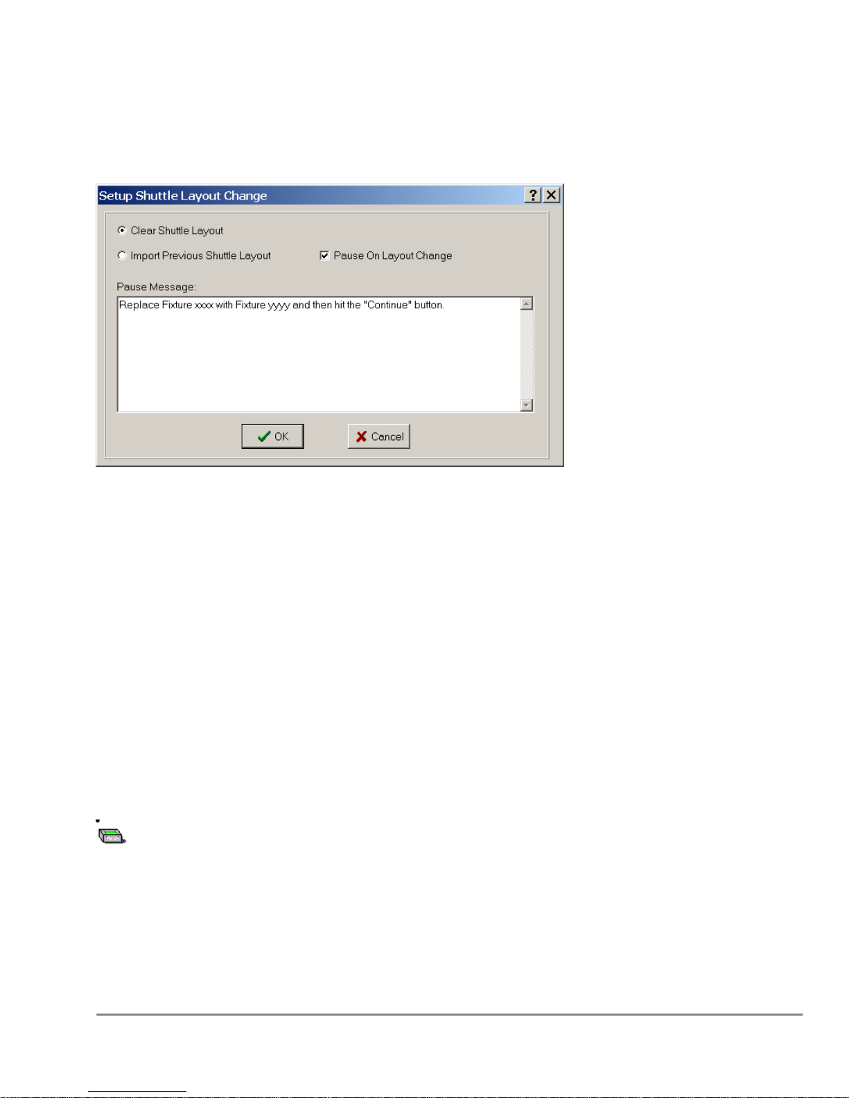
Conditions
There are no requirements for this function.
Remarks
Clear Shuttle Layout
Clear Shuttle Layout gives the user an empty shuttle to work with when changing the
fixtures and components.
Import Previous Shuttle Layout
Import Previous Shuttle Layout brings all of the hardware previously installed on the
shuttle, and allows the user to add/change the existing fixtures and components.
Pause On Layout Change
Pause On Layout Change will pause the running program, and post the message typed
into the Edit Box below. The user has an infinite amount of time to change the layout of
the shuttle. The program will not resume until the user clicks the OK Button.
3.29 SPE Pressure Vacuum Operation
The SPE Pressure/Vacuum function allows for both positive pressure and vacuum to be
applied to a filter plate.
Conditions
This function requires that the vacuum controlled mini-trap and the software controlled
pressure regulator options be installed.
Quadra 4 Operator Manual
78
Tomtec
Page 79
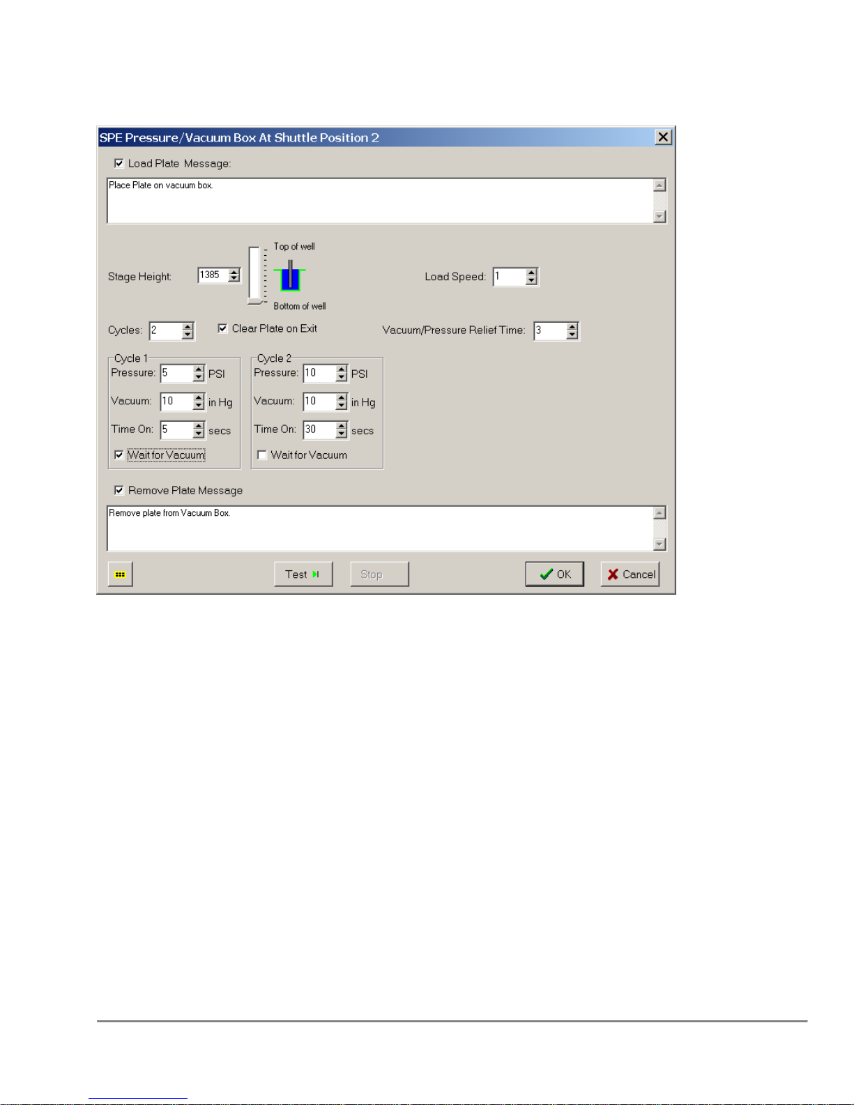
Remarks
Plate Load Message
Message to prompt the operator to prepare for this function.
Stage Height
Height to move the vacuum box/plate to the pump pressure fixture. Note that the stage
will force the vacuum box/plate into the pressure fixture, because of this the STAGE
SAFETY is bypassed.
Cycles
The function can do up to four pressure/vacuum cycles. The cycle can operate both
vacuum and pressure or either. To turn off either set the value to zero.
Clear Plate on Exit
When checked, a puff of air will be cycled to free the plate from the pump pressure
fixture.
Vacuum Pressure Relief Time
Time required to bleed off the vacuum/pressure to free the plate from the vacuum box.
Quadra 4 Operator Manual
79
Tomtec
Page 80
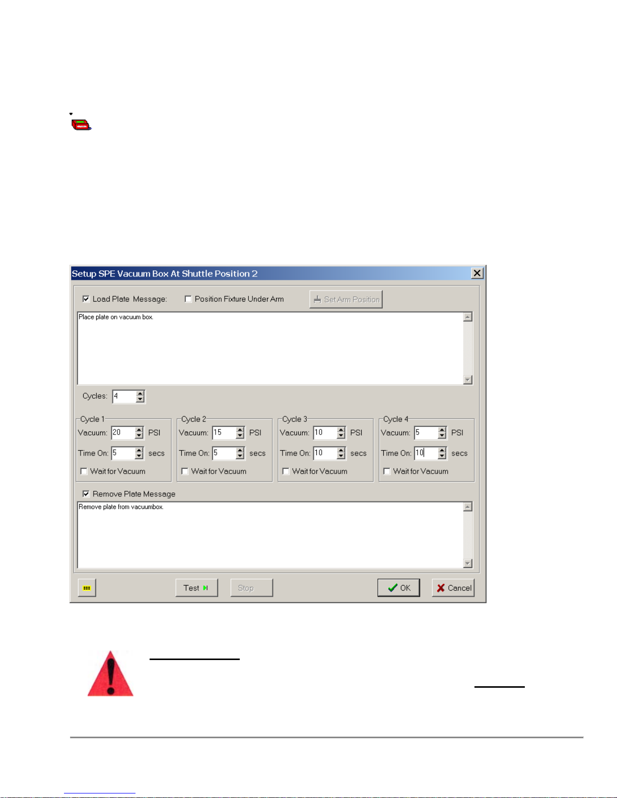
3.30 SPE Vacuum Box Operation
Program control for the SPE Vacuum box.
Conditions
The SPE Vacuum Box operation requires a vacuum box and a vacuum controlled MiniTrap.
Remarks
Important Note: Powered accessories such as Vacuum Traps,
Autotraps and Shaker Nests, should not be connected with the
Quadra 4 powered on. Please turn off AC power BEFORE
connecting these accessories.
Quadra 4 Operator Manual
80
Tomtec
Page 81
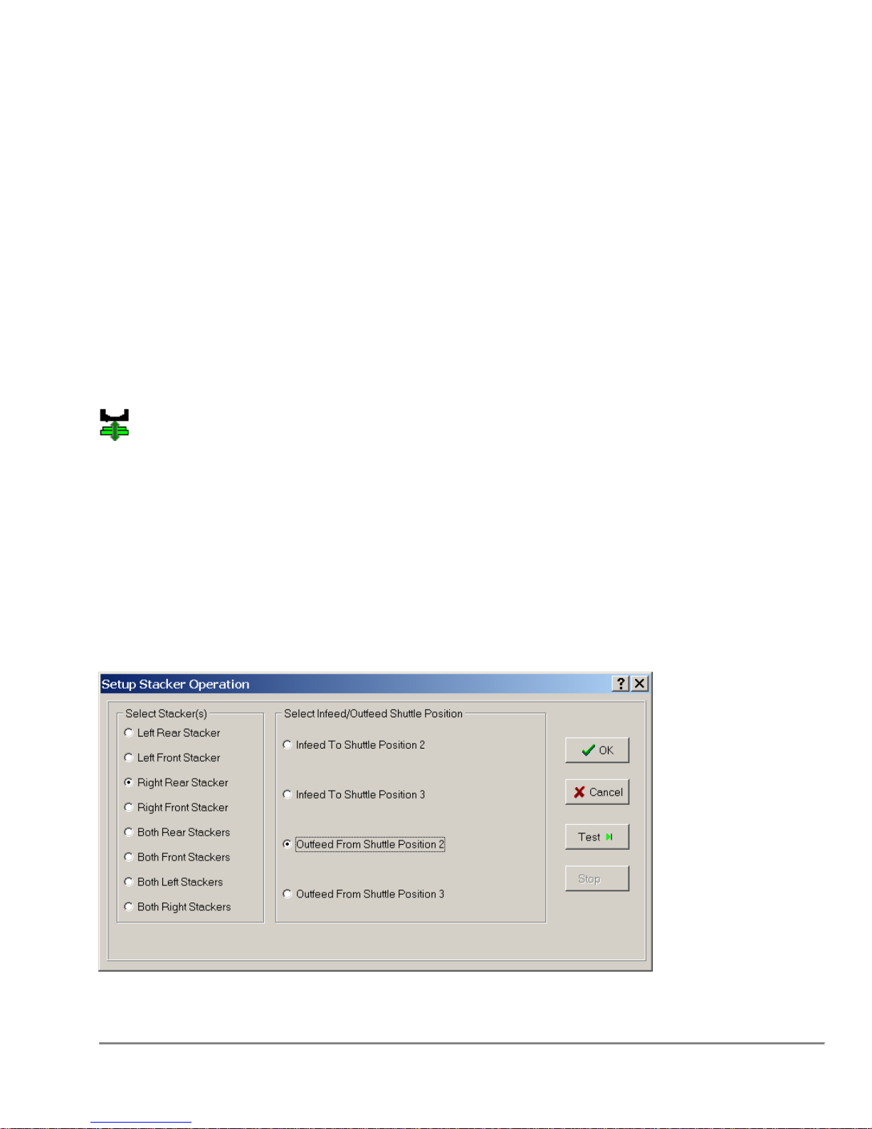
Load Plate Message
When checked, a custom message will be displayed to instruct the operator. If not
checked, a generic message will be displayed.
Cycles
The function can have up to four vacuum cycles. Each cycle will set the inches (0->25)
of vacuum to use and the duration. When the "Wait for Vacuum" box is checked, the
function will delay until the vacuum reaches the desired setting.
Remove Plate Message
When checked, a custom message will be displayed to instruct the operator. If not
checked, a generic message will be displayed.
Note: This operation requires that special hardware be installed.
3.31 Stacker Operations
The Stacker Operations Function allows the user to Infeed and Outfeed plates from the
stackers at various times throughout the length of the program.
Conditions
The Stacker Operations Function requires you to select a shuttle position that has a
plate capable fixture. The fixture also has to allow stacker related functions.
Remarks
Quadra 4 Operator Manual
81
Tomtec
Page 82
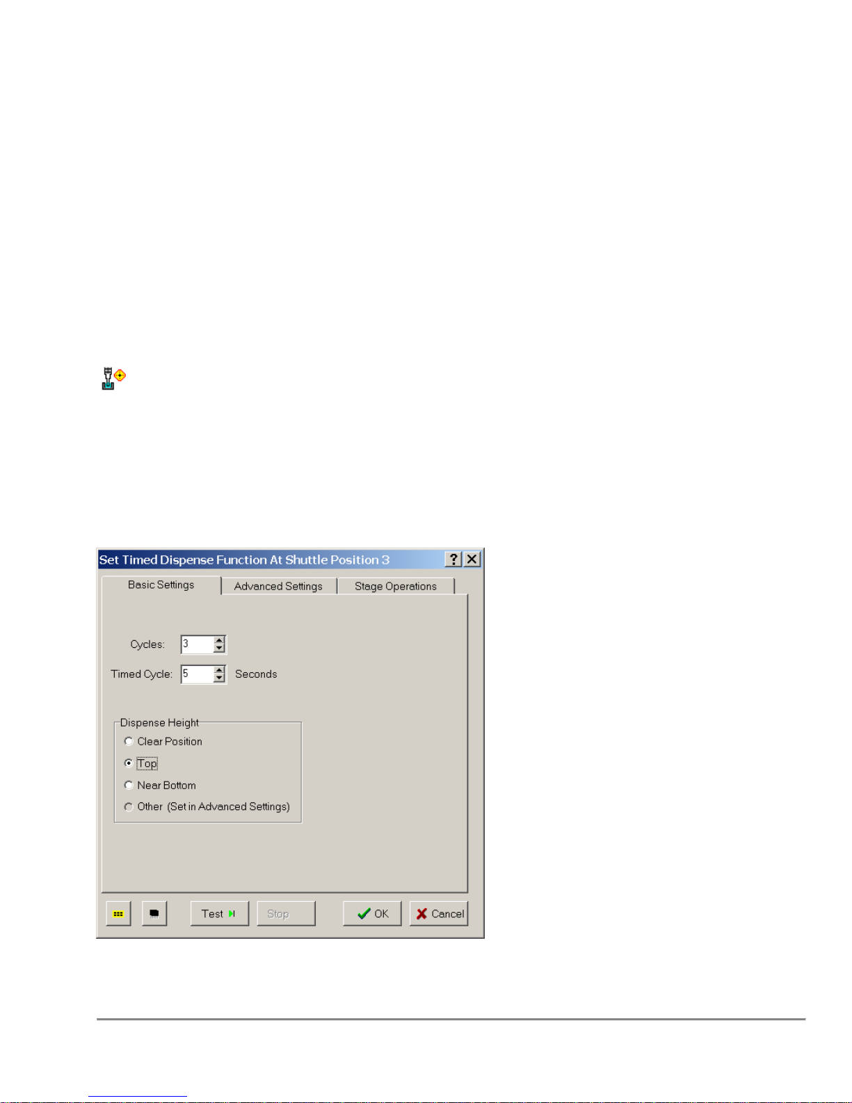
Select Stacker
Select the stacker you would like to Infeed from or Outfeed to.
Infeed or Outfeed Shuttle Position
Select you appropriate operation, whether you are bringing plates onto the shuttle
(Infeed), or returning them to their original, or different stacker (Outfeed).
Disable Lid Capability
Disable Lid Capability indicates that if the stacker supports lids than the plate
being processed does not have one. This is necessary for thin plates.
3.32 Target Method
The "Target Method" function is available for the 450ul Timed Dispense head and the
20/50/250ul DMV head.
The function is a tightly coupled Aspirate and Dispense of small volumes.
Remarks
Quadra 4 Operator Manual
82
Tomtec
Page 83

TARGET(SOURCE)
The "Target" volume. height, speed, etc. Set the "Source" plate volume. The operation
will pre-wet the tips, aspirate the default tip volume, and then dispense the delta to
achieve the target volume.
TARGET(DESTINATION)
The "Dispense" height, speed, timed dispense height, etc. Set the Destination" plate.
Generally all but 3ul is dispensed at the destination plate. The remainder is dispatched
by a timed dispense function. If the volume is less than 3ul, the dispense is skipped,
and the timed dispense will be done.
NOTES: TARGET METHOD PIPETTING
The target method takes advantage of the fact that higher positive pressures
may be developed within the tip on a dispense motion, compared to the low
negative pressures that are available for aspiration. The target method is only available
for pipetting volumes less than 50µL. If target method is selected on the source
characteristics of any template, it will automatically aspirate and dispense 30µL, first
to pre-wet the tip. Then it will aspirate a 50µL volume and automatically
dispense back to the target volume to be dispensed. For example, assume 10µL is
the desired target volume. 50µL is aspirated and 40µL is automatically dispensed back
to the source with the tip submerged in the source liquid.
If target injection is selected for the destination characteristics, then the following action
will occur if the delivery volume is less than 50µL. The dispense will automatically be
made at the top of the well (as determined by the database for the plate selected in the
deck layout. You must use the correct plate layout). All but 3µL of the tip volume will be
dispensed by piston displacement.
The final 3µL will be blown out using the time dispense function. The air pressure for the
time dispense function should be set at 3 psi.
The 3µL blow out volume was derived empirically. At 8µL, the fluid flow was not
fast enough to overcome the surface tension forces at the orifice and the dispensed
liquid may form a drop on the tip exterior. The small 3µL volume and 3 psi driving force,
accelerates the liquid fast enough to minimize or eliminate the clinging drops on the tip
exterior.
Quadra 4 Operator Manual
83
Tomtec
Page 84
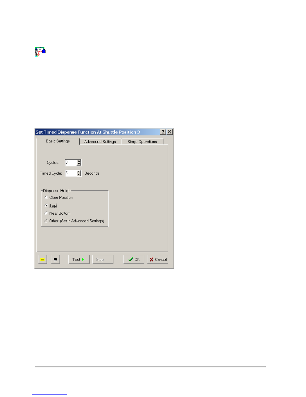
3.33 Timed Dispense
To deliver air or reagent from the Internal Air Reservoir
Conditions
To Time Dispense you will need to select a shuttle position with a plate
capable fixture.
Remarks
Cycles
The number of times the pinch tube clamp opens to deliver air.
Height
The height which the tips will deliver air to the well.
Note: Check air pressure to avoid high pressure dispenses that spill liquid (this
can be done from the Utility).
Quadra 4 Operator Manual
84
Tomtec
Page 85
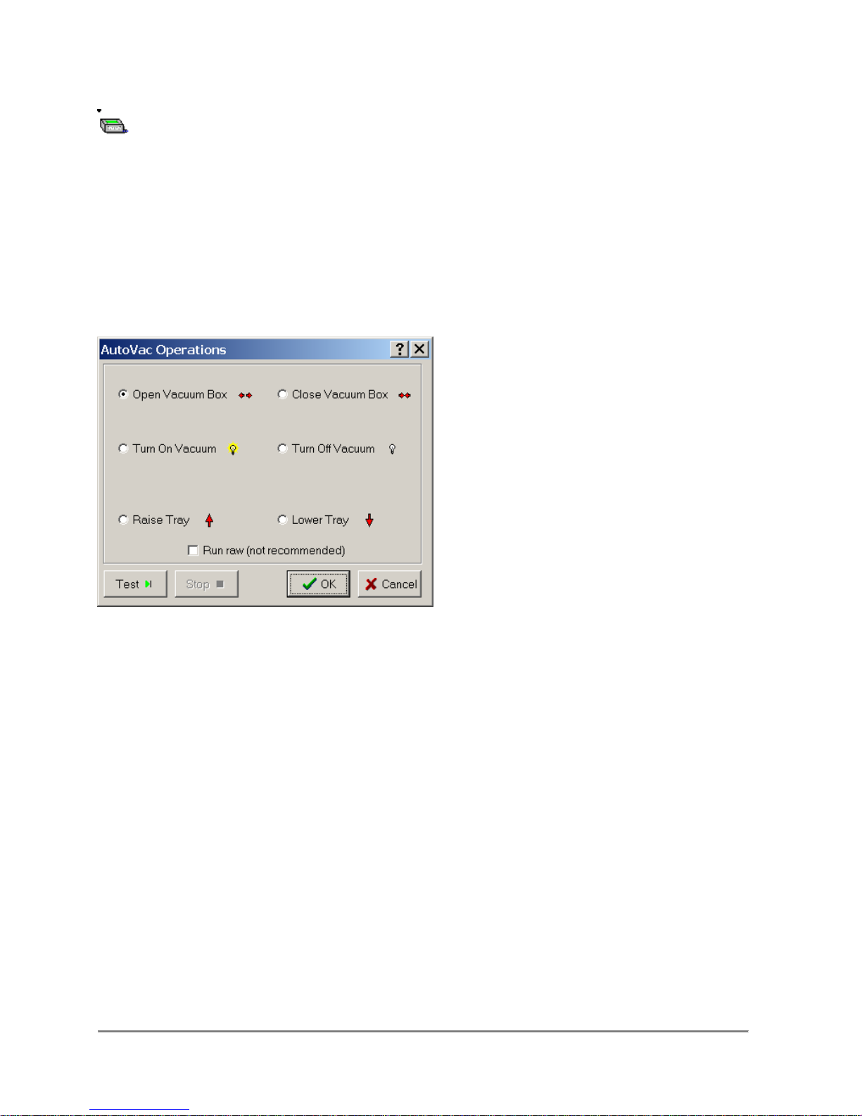
3.34 Vacuum Box Operation
The vacuum box operation is used to control the automated vacuum box.
Conditions
None
Remarks
Open Vacuum Box performs vacuum off, tray down, open box, and then tray
up. If Run Raw is checked then the box will just open.
Close Vacuum Box performs vacuum off, tray down, and then close box. If Run Raw is
checked then the box will just close.
Turn On Vacuum performs vacuum off and then raises or lowers the tray (as indicated
by the checkbox) before turning on the vacuum. If Run Raw is checked then the
vacuum will just turn on.
Turn Off Vacuum performs vacuum off and then raises or lowers the tray (as indicated
by the checkbox). If Run Raw is checked then the vacuum will just turn off.
Raise Tray performs vacuum off and then raises the tray. If Run Raw is checked then
the tray will just raise (Warning: It is not recommended to raise the tray while vacuum is
on).
Quadra 4 Operator Manual
85
Tomtec
Page 86
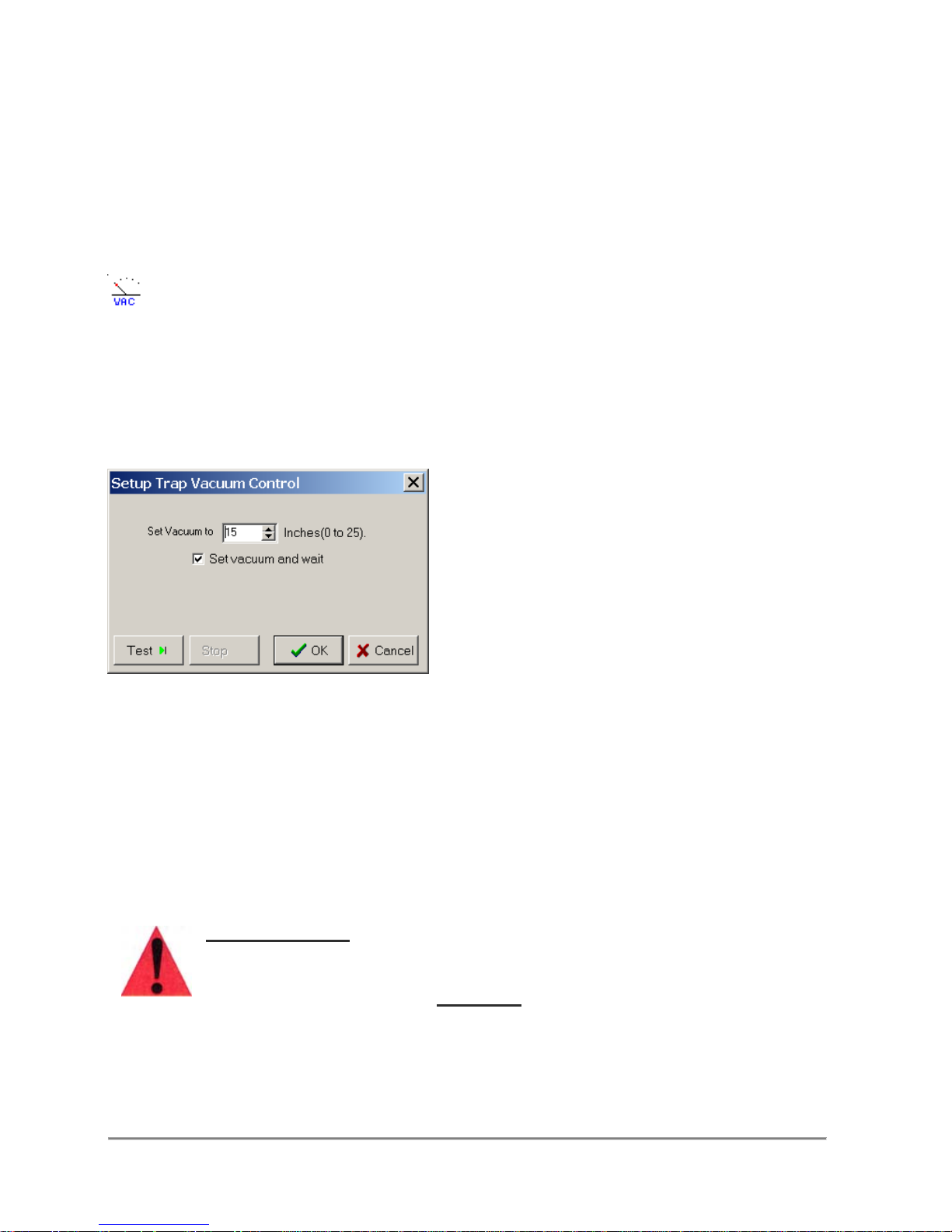
Lower Tray performs vacuum off and then lowers the tray. If Run Raw is checked then
the tray will just lower (Warning: It is not recommended to lower the tray while vacuum
is on).
Run Raw when check will circumvent implied action for the selected operation (not
recommended). See each operation for the effect of checking this option.
3.35 Vacuum Control
This function allows the user to set the trap vacuum.
Conditions
The software controlled Mini-Trap feature must be installed.
Remarks
Set Vacuum - Sets the desired vacuum to 0 to 25 inches of mercury. Note that a 0
setting turns the vacuum off.
Set Vacuum and Wait/No Wait - When the "wait" feature is selected, the program will
pause until the trap reaches the desired vacuum. This usually takes from 10 to 20
seconds, depending on the vacuum source. when the "No Wait" feature is selected, the
trap vacuum is set, but the program will not pause.
Important Note:
Powered accessories such as Vacuum Traps, Autotraps and Shaker
Nests, should not be connected with the Quadra 4 powered on.
Please turn off AC power
BEFORE
connecting these accessories.
Quadra 4 Operator Manual
86
Tomtec
Page 87
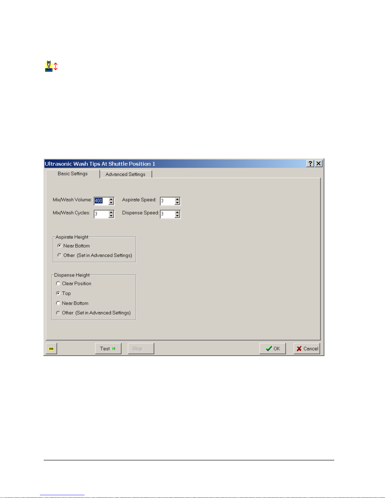
3.36 Wash
A series of alternating aspirate and dispense steps to cleanse the tips.
Conditions
This function requires Ultrasonic Wash to be on the specified shuttle position in order for
this function to operate properly.
Remarks
Blow Out Volume
See Dispense Function.
Blow Out Height
See Dispense Function.
Mix/Wash Volume
See Mix Function.
Quadra 4 Operator Manual
87
Tomtec
Page 88

Mix/Wash Cycles
See Mix Function.
Aspirate Speed
See Aspirate Function.
Aspirate Height
See Aspirate Function.
Dispense Speed
See Dispense Function.
Dispense Height
See Dispense Function.
Wash Delay Timers
Pre-wash time and post-wash time are used with flow wash. Pre-wash time is the
number of seconds to delay before pipetting after water flow has started. Post-wash
time is the number of seconds to delay before turning off the water flow after pipetting.
Dry/Rinse Tips
The Dry/Rinse Tips option allows the user to blow out an air gap at the end of the wash.
Timed Dispense
See Timed Dispense Function.
Drop Stage after Tip Wash
See Additional Options.
Quadra 4 Operator Manual
88
Tomtec
Page 89
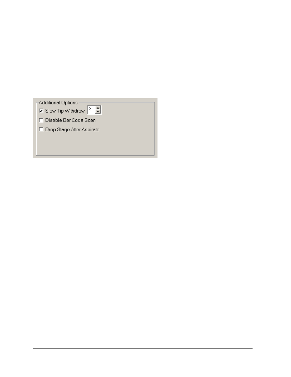
3.37 Program Operations Common Options
Several Functions above have the same Options. Instead of repeating the same
descriptions within each of the Functions, the Common Options are all discussed in this
section.
3.37.1 Additional Options
Slow Tip Withdraw
This options will extract the tip from the liquid at a slower speed to help reduce residual
liquid on the exterior of the tip. The tip withdraw speed can be set from 1 to 4, a speed
of 0 turns off the slow withdraw function.
Drop Stage After ...
This option brings the stage to a zero height after the function has concluded.
Disable Bar Code Scan
If the bar code scanner is enabled in the logging options section, this option allows the
user to disable reading the bar code for the current step.
Enable Liquid Following
Allows the user to minimize tip submersion during an aspirate or dispense function.
Once the initial aspirate or dispense height is programmed, the software automatically
adjusts the tip position in a well deeper or higher, respectively, as the liquid level in a
reservoir or micro-plates changes. This rate of adjustment is based on the Well Rate
parameters assigned in the micro-plate and reservoir database.
Quadra 4 Operator Manual
89
Tomtec
Page 90
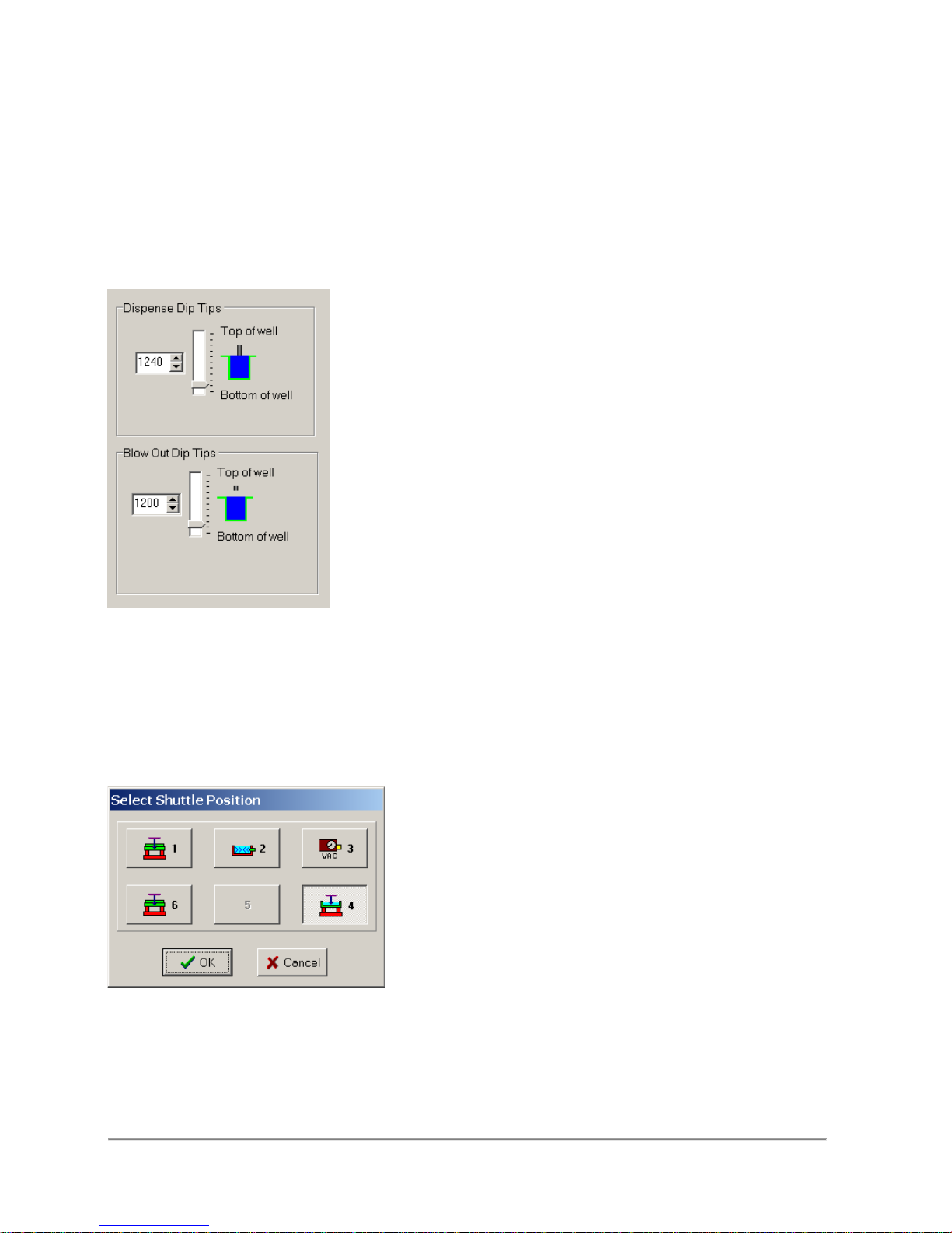
3.37.2 Dip Tips
The Dip Tips operation is available for the Dispense, Mix, and Empty Sample Functions.
Conditions
The operation is used to remove excess liquid from the tips after executing the function.
Remarks
The Dip Tip setting is a Delta from the Dispense/Blow Out/Empty height. For example if
the dispense height was set to 1000, the stage will move 19 steps to 1019 and then
back to 1000.
3.37.3 Select Shuttle Position
This function allows the user to change the shuttle position of a step without having to
recreate the step. Grayed positions are unavailable for the current function.
Quadra 4 Operator Manual
90
Tomtec
Page 91
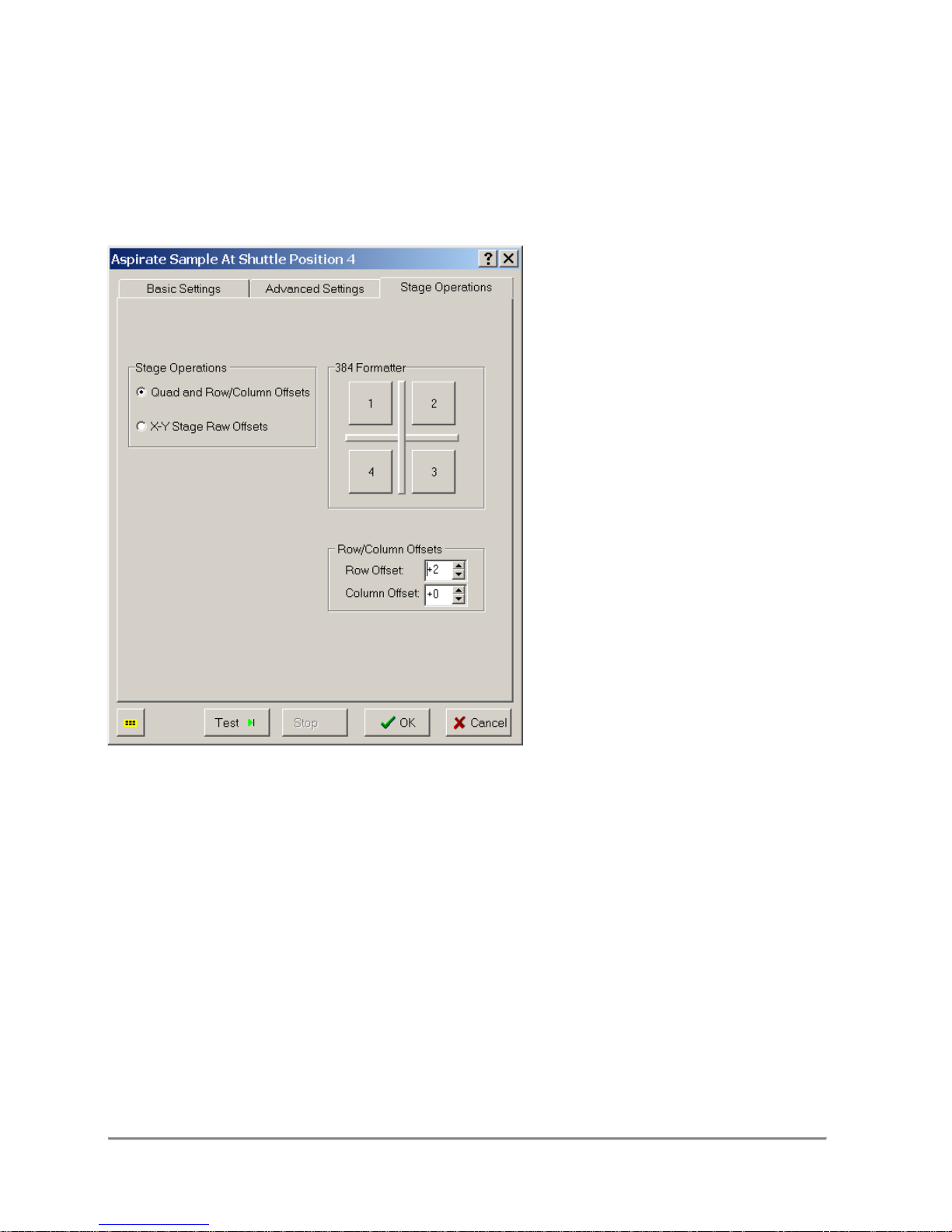
3.37.4 Stage Operations
You have two options to configure the stage for special plates. One is Quadrant
& Row/Column Offsets, and the other is X-Y Raw Stage Offsets. These functions
allow you to take a 96 tip head, and pipette to a 384-Well plate.
Quad & Row/Column Offsets
Note, since the Quadra 4 SPE does not have an indexing stage, the Stage Operations
selection is locked out.
Using the Quadrant Formatter feature, it is easy to take a standard 96 Tip head, and
format it to pipette from a 384-Well Plate.
Simply by selecting what particular quadrant you are aspirating from, the application can
locate the proper well.
Along with quadrant reformatting, you can also specify Row and Column Offsets.
What this function does is allow the user to move the plate along the X and Y axis
in order to line up the tips with another particular well. Offset values represent tip
position relative to standard labeling for plates with the same density of wells as tips.
Row Offset will position the tips one row up or down if the value is negative or positive
respectively. Column Offset will position the tips one column to the right or left if the
value is positive or negative respectively.
Quadra 4 Operator Manual
91
Tomtec
Page 92
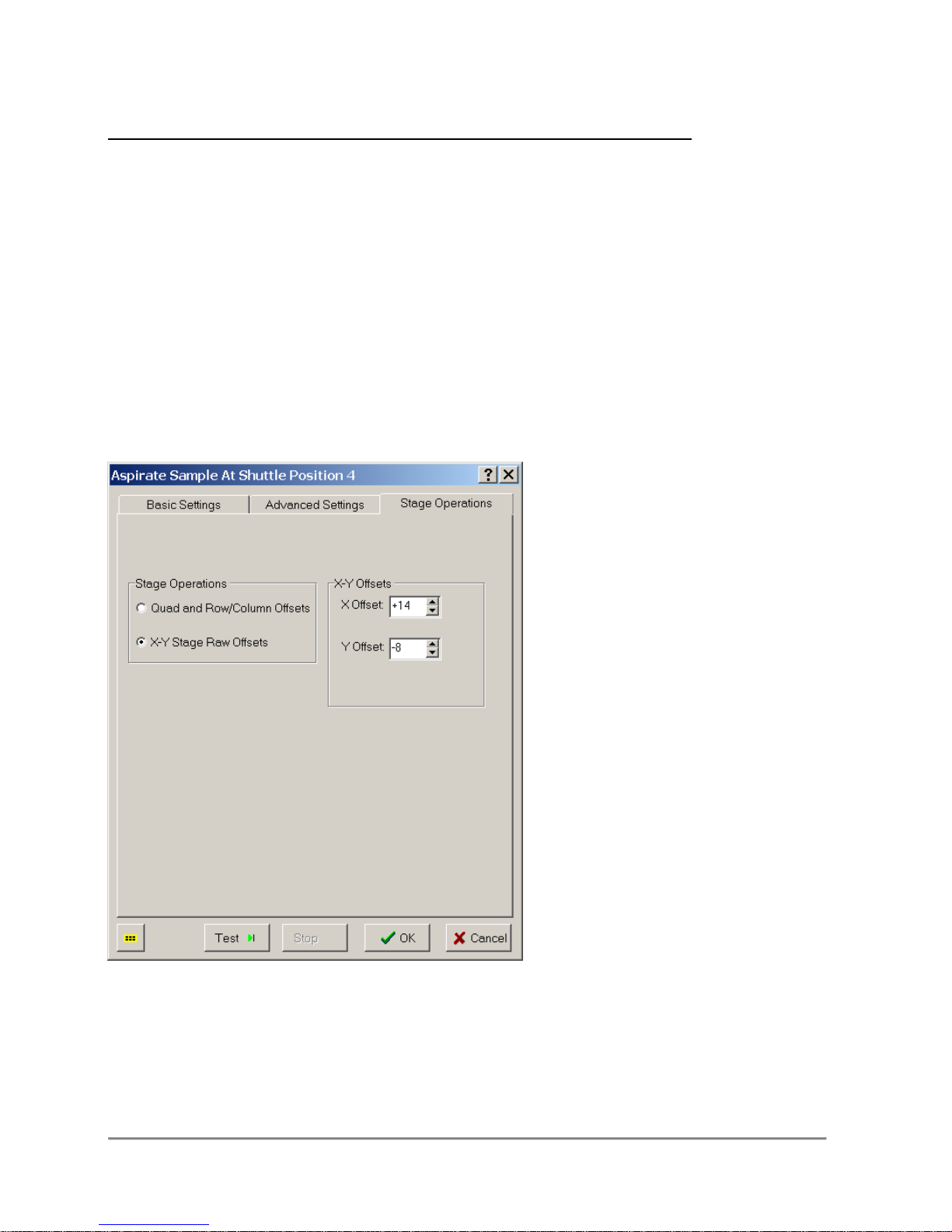
The following are a couple of examples that may help you understand this concept
more:
Assuming you have a 96 Well Plate, and one tip inserted into well E6...
1. If you want to pipette from Well E7, you would set your column offset to +1.
2. If you want to pipette from Well E5, you would set your column offset to -1.
3. If you want to pipette from Well D6, you would set your row offset to -1.
4. If you want to pipette from Well F6, you would set your row offset to +1.
5. If you want to pipette from Well F7, you would set your row offset to +1, and your
column offset to +1.
6. If you want to pipette from Well D5, you would set your row offset to -1, and your
column offset to -1.
When using higher density plates with a lower density tip head, such as a 384 well plate
and a 96 tip head , Quadrant Formatter and Row\Column Offsets must be used in
conjunction with each other to reach the desired well.
X-Y Stage Raw Offsets
Using the Raw setting allows the user to manually enter the number (of steps) that the
stage has to move in either direction in order to get at the well you need to. Values
represent tip movement in a Cartesian plane (although the stage actually moves.) In a
standard 96-Well plate, there are 577 steps between each well, and in a standard 384Well plate, there are 288 steps between each well. Here are some more examples:
Quadra 4 Operator Manual
92
Tomtec
Page 93

Assuming you have a 96 Well Plate, and one tip inserted into well E6...
1. If you want to pipette from Well E7, you would set your X Offset to +577.
2. If you want to pipette from Well F6, you would set your Y Offset to -577.
Assuming you have a 384 Well Plate, and one tip inserted into well C3...
1. If you want to pipette from Well C4, you would set your X Offset to +288.
2. If you want to pipette from Well D3, you would set your Y Offset to -288.
3.37.5 Touch Off
The side touch off is used to remove excess liquid from the tips.
Conditions
This option is selectable in the Dispense, Mix, and Empty Sample functions.
Remarks
The multi-point side touch off is available for full x-y indexing stages. The X touch off is
the standard single point movement. The XY, and XY -X -Y touch offs are 2 and 4 point
movements.
All touch off movements start from the center of the well to the offset and back to the
center for each point.
Quadra 4 Operator Manual
93
Tomtec
Page 94
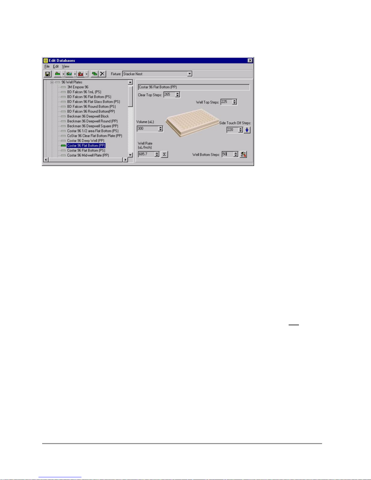
4.0 Database Editor
Getting Started with DBEditor
The Database Editor allows you to manipulate the values for specific plates and
fixtures easily and reliably. You can start the Database Editor by select the
Database Menu > Edit Plate, Reservoir, and Fixture Database.
The left side of this form displays a tree for Plates, Reservoirs, and Fixtures. Under
each primary branch, there is the first level of categories for each item. Plates are
separated by the number of wells, and Fixtures are separated by their basic
functionality.
When pipetting liquids, an important parameter is the location of the pipettor tip within
the well. This is accomplished with the use of the plate and reservoir database on all of
Tomtec’s Quadra’s.
When aspirating liquid, the tips should be near the bottom of the well, but not pinned.
When dispensing liquid, there are two basic choices. If it is desired to mix the
dispensed liquid with the contents of the well, then the dispense should be made at the
bottom of the well. Again, near the physical bottom, but not pinned. If a non contact
dispense is to be made, then the tips must be at the top of the well, but within the
confines of the top rim.
Tomtec’s Quadra design allows another important pipetting feature. It provides the
ability to blow low air pressure through the tip orifices. This is referred to as the “Timed
Dispense Function”. The low air pressure setting is controlled by a precision pressure
regulator. Normally, it is set from 0.5psi to 1.0psi. This surge of positive air pressure is
used to clear the residual that is retained within the tip orifice, due to capillary action. It
is of significant importance for pipetting accuracy at small volumes.
Quadra 4 Operator Manual
94
Tomtec
Page 95

The timed dispense function may also be used for true non-contact dispensing. For that
application, all but the last 3µL of a dispense volume is dispensed using piston
displacement. Then this last 3µL is cleared with the “Timed Dispense Function”. The
3µL slug of liquid normally has sufficient kinetic energy to clear the orifice without
leaving clinging drops.
Where should the “Timed Dispense Function” be made? Normally the tips should be
at the top of the well, but within the confines of top rim. However, if the well volume is
near the top, there is concern for splashing the well contents.
Tomtec’s software provides a third tip height in relation to the well. This is “Clear
Height”. This is defined when the tips are .060 inches above the top of the wells. This
height is used if the stage must index the plate under the tips, for serial dilution as an
example.
In summary, the Quadra software allows the user to set very specific tip heights.
However, this is too tedious and not required for normal use. It may be of value on a
specific protocol. For normal use, the Quadra database software provides 3 specific tip
locations for the specific plate or reservoir that has been selected. They are as follows.
Clear Height: The tips will clear the top of the plate by .060 inches.
Top of Well: The tips are located .060 inches below the top rim of the
well.
Bottom of the Well: The tips are .030 inches from touching the bottom of the
well.
4.1 The Menu Bar
The File Menu
The File Menu consists of two main functions: Importing records from another file, and
exiting the program.
From the File Menu you can Import Plates, Reservoirs, and Fixtures. When
selecting the appropriate category, a dialog box appears.
This Dialog box will allow you to import from database files stored in the Quadra 3 2.6.x
format (*.txt) and the new 3.0.x format (*.dat).
Upon selecting a file, the Import Window will appear. Please refer to the section on
Importing Plates and Fixtures for a detailed explanation of the importing process.
Quadra 4 Operator Manual
95
Tomtec
Page 96
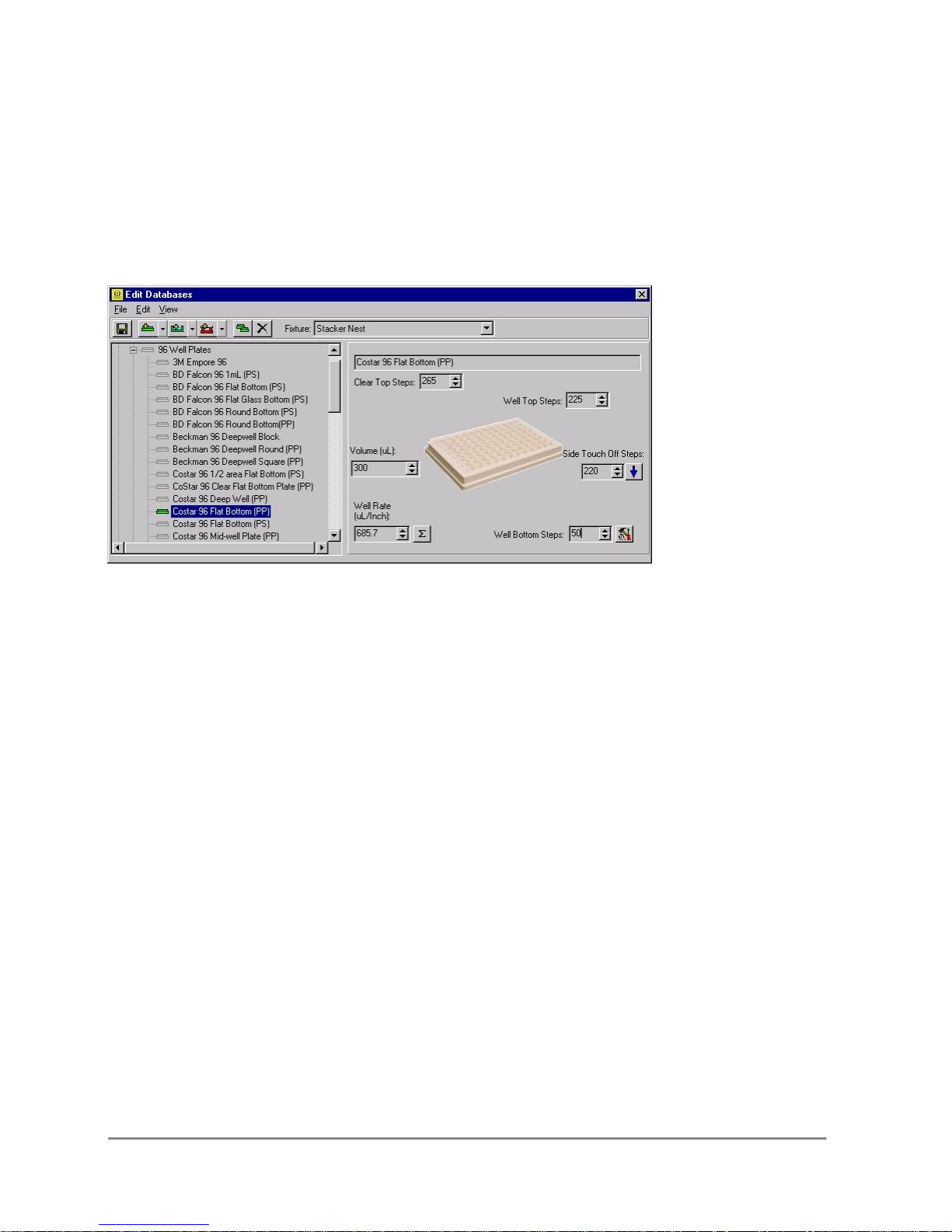
The Edit Menu
The Edit Menu allows you to add new records, Copy items, delete items, and also open
the Quadra Utility screen when required.
The View Menu
The View Menu gives you the option for customizing the view of the screen by
either including the small images next to their relative item, or negating them.
4.2 The Plate Panel
When setting the parameters for a plate or reservoir, the Plate Panel will appear on the
right hand side of the form. This form will allow the user to add/change the plate name,
Clear Steps, Top Steps, Bottom Steps, the Volume, the touch off steps, and also
calculate the well-rate, a feature that controls the liquid follow function.
Clear Top Steps
Clear Top Steps is the number of steps the stage has to travel beyond the fixture in
order to clear the plate/reservoir entirely for serial dilution or quadrant moves.
Top Steps
Top Steps is the number of steps the stage has to travel beyond the fixture in order to
set f the tips at the top of the plate.
Side Touch Off Steps
Side Touch Off Steps is the number of steps the stage indexes in the horizontal
direction, in order for the side of the tips to touch the side of the well.
Bottom Steps
Bottom Steps is the number of steps the stage has to travel beyond the fixture
in order for the tips to touch the bottom of the wells. (Not necessarily the bottom
of the plate or reservoir.)
Quadra 4 Operator Manual
96
Tomtec
Page 97
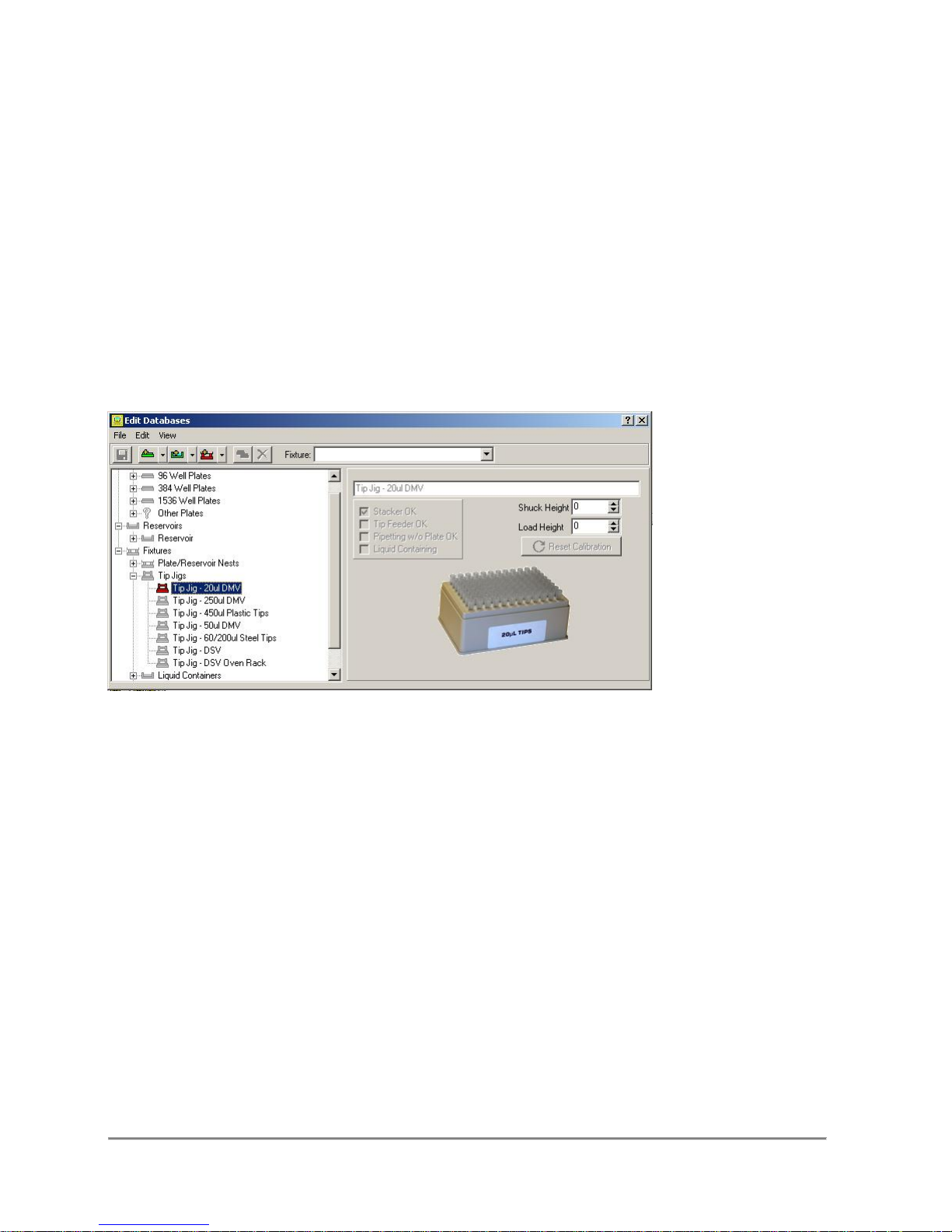
Volume
Volume is the amount of liquid (in µL for plates and mL for reservoirs) that a single well
or reservoir can hold.
Well Rate
Once Top Steps, Bottom Steps, and Volume are entered, it is possible to estimate the
well rate by clicking on the button next to the field. This field is user editable, and it is
advised that you test, and calibrate the well rate manually. The application will only
provide an estimate.
4.3 The Fixture Panel
Fixtures are easier than plates to calibrate because there is only one setting,
the Calibration Height. This is, by definition, the height at which the tips meet the
fixture, without pinning the fixture to the stage.
There are several fixtures, preinstalled into the software, that are not usereditable. The only attribute the user may edit is the calibration height. Any new
fixtures, or custom fixtures are user editable, and must specify whether or not they can
operate with a Quadra Stacker, whether or not they can operate with a Tip Feeder, and
whether they can be pipette from/to.
Tip jigs are fixtures that require no user intervention. All tip jigs have a load height of
zero. If any value is inserted into this field, it will override the load height set in the
system parameters function. The same is true for the shuck height.
After setting the Load Height, if you are unsatisfied with the result, you may
click the Reset Calibration button to return to the original value, only before you
save. The application will prompt you to save any changes when you switch records, or
close the application.
Quadra 4 Operator Manual
97
Tomtec
Page 98

A new category has been added, called, "Liquid Containers." These are fixtures
that contain calibration heights as well as top steps so when programming a
function, the dialog can properly represent tip position inside the container.
4.4 The Touch Off Panel
The Touch Off Panel is a special feature that facilitates the accurate depicting of the
value for the Side Touch Off Step control.
The process is as follows:
1. Open up the Quadra Utility, and position the tips in the center of the designated well,
with the tips just barely inside the well.
2. Close the Quadra Utility.
3. Enter the number of steps for Side Touch Off.
4. Click Test Touch Off to move the tips.
5. The tips will hold position until the user clicks yes or no to accept the value.
6. Click No and Repeat steps 4-6 until value is accurate.
7. Click yes to accept the value and populate the Side Touch Off Steps field.
4.5 Importing Plates-Reservoirs-Fixtures
Importing Plates/Fixtures is Quick and Easy. Simply click on the File Menu and
select Import Plates/Reservoirs/Fixtures.
Navigate to the proper folder and click Open to open that particular file.
A dialog box will automatically appear. The items on the left are those records
that are available in the selected file, and the items on the right are those you wish
to import. Click on the Add and Remove buttons to carry records from one side to
another.
When you are finished selecting those items you wish to import, click on the Import
button to finalize the procedure.
Quadra 4 Operator Manual
98
Tomtec
Page 99
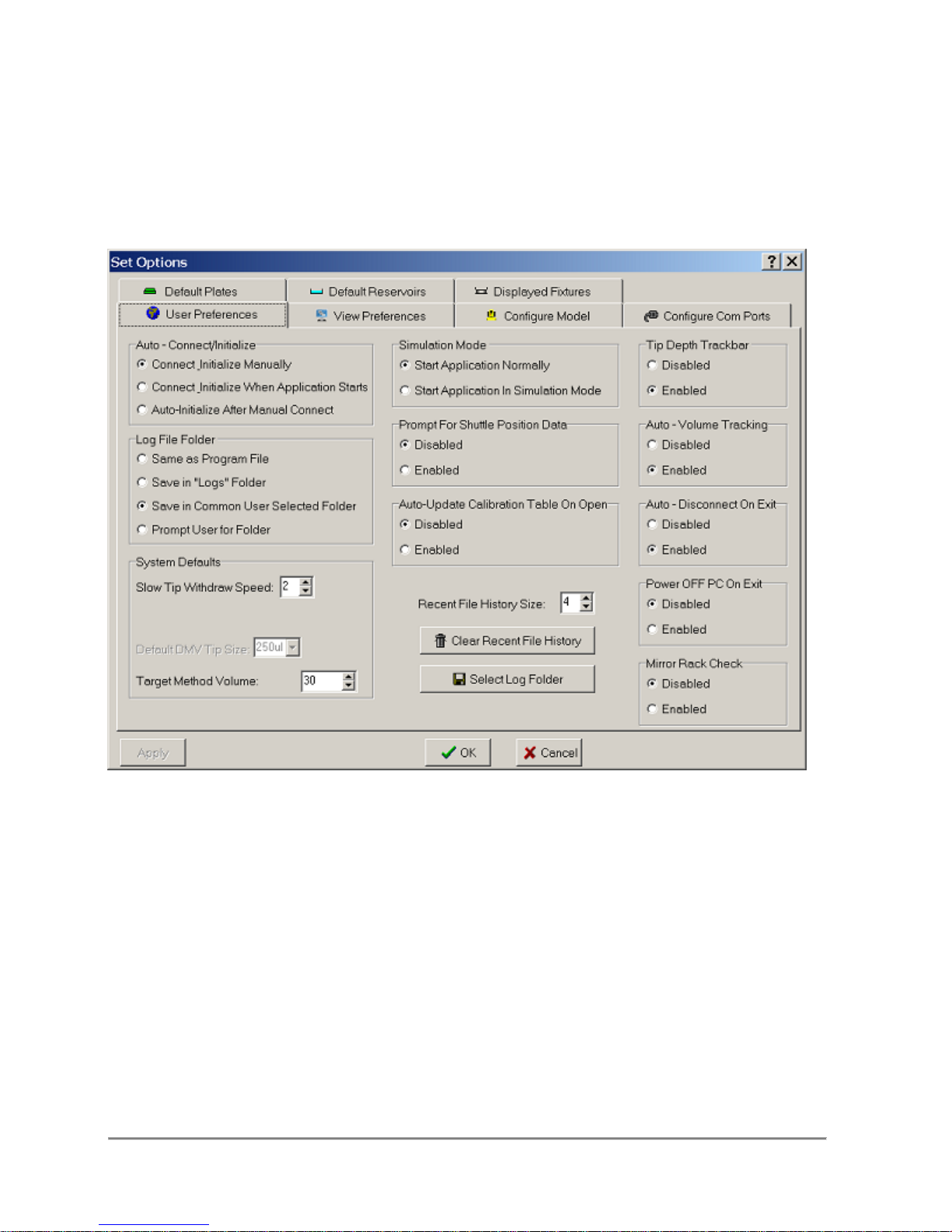
5.0 Options
5.1 User Preferences
Auto - Connect/Initialize
The operator can set the application to:
1. Manually connect and Initialize the Quadra
2. Connect to and then initialize the Quadra when the application starts.
3. Auto-Initialize the Quadra after connecting.
Auto - Disconnect On Exit
When disabled, the operator has to use the "Disconnect" tool bar or menu item to
shut down the Quadra. When enabled, the application will automatically call the
"Disconnect" function when the application is exited.
Quadra 4 Operator Manual
99
Tomtec
Page 100

Simulation Mode
The application can be set to either run as simulation on the screen only or run on the
Quadra.
Prompt For Shuttle Position Data
When disabled, the operator has to "right" click on the shuttle position to add any
additional data about the position. If enabled, the operator will be prompted for
additional data every time there is a change.
Log File Directory
Designates where the log files are created and saved.
Recent File History Size
Sets the number(0 - 4) of program files to save to the recent file history list.
Tip Depth Trackbar
When enabled, a track bar is displayed between the edit box and the tip in well graphic
for editing stage heights. This provides an additional tool for scrolling quickly through
the stage heights. Without the track bar, scrolling can be accomplished by directly
scrolling the tip in the well or using the up/down buttons in the edit box.
System Defaults
The default slow tip withdraw speed, 1 to 4, for all functions that have this option. Note
that a speed of 0(zero) will turn off this option.
When checked, the default mode for shucking tips on pinch tube equipped pumps will
be to open the pinch tubes before shucking, and closing after. If the "DMV" head is
selected, the default tip volume can be set to 20, 50, or 250 µL. If the "Target Method"
function is checked, the default target volume can be set.
Auto-Pinch Tubes Open On Disconnect
This option is enabled by default every time a pinch tube equipped head is selected.
When enabled it will open the pinch tubes after a ten second count down:
The operator has the option to abort the operation anytime during the countdown.
When this option is disabled, the operator will be prompted to open the pinch tubes.
Quadra 4 Operator Manual
100
Tomtec
 Loading...