

Page 1
Page 2
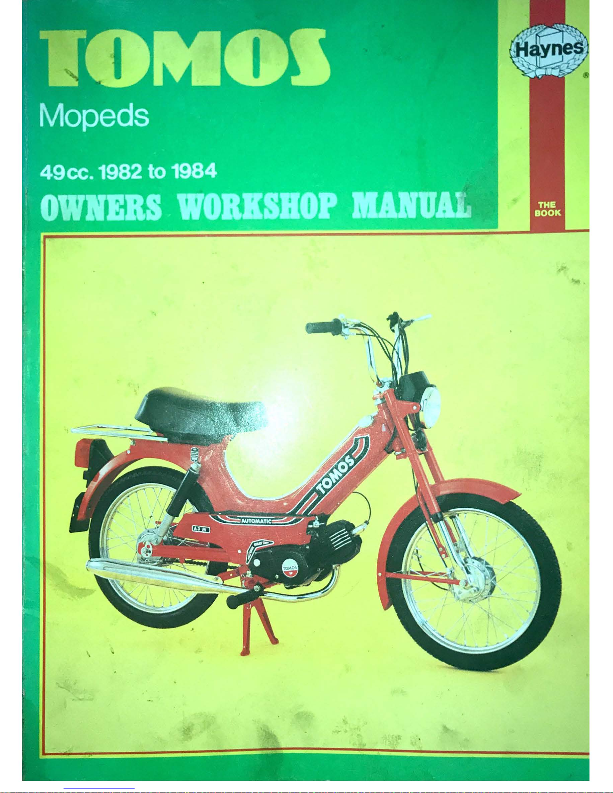
Tomos
Mopeds
Owners
Workshop
Manual
Pete
Shoemark
Models
covered
A3K. 49cc. Introduced
November
1982
A3M. 49
cc.
Introduced
August
1984
A3MS. 49cc. Introduced
July
1984
A3ML.
49cc. Introduced
July
1984
ISBN 1 85010
062
4
© Haynes Publishing Group
1984
All rights
rnerwd
. No
put
of this
book
may
be
reproduced
or
transmitted
in
any
form
or
by
any
means, electronic
or
mechanical. i
ncluding
photocopying,
recording
or
by
any information
sto..-ge
or
retriewil
system
, wi
thout
permission
in
writing
from
the
copyr
ight
holder
.
Printed
in
England
HAYNES PUBLISHING GROUP
SPARKFORD
YEOVIL
SOMERSET BA22 7JJ ENGLAND
HAYNES PUBLICATIONS
INC
861 LAWRENCE
DRIVE
NEWBURY
PARK
CALIFORNIA
91320 USA
Britlall lib••rv Ce1el09uinv in
Publicelion
D•t•
St.o..mA P
ete
Tomas
lnO!l<'ds
owners
WOO.shoP manual,
I M
ope<l
s - ll1aln
1en
• nce and repaii - Tomos moued
1. nu.
529 2e· 12 T
l45
3 T6
ISBN
1-85010--062~
Page 3
Our thanks are
due
to
Dwek
International
Limited
. the
UK
importer and di
stributor
of
the
Tomos
range. and in
particular
to
Stewart
C Bronstein
of
the
above
company
who
arranged the
loan
of
the machine used in
the
woritshop
project. provided
the
technical
information on
the
models
covered
by
the
manual
and checked the
About this manual
conten
ts
of
the
manual
for
technical
accuracy.
The
Avon
Rubber
Company
supplied information
on
tyre careanc
fitting
. and
NGK
Spark
Plugs
(UK)
Ltd
provided
informat
ion
on
plug
maint
enance a
nd
electrode
conditions
.
Page 4
Contents
Page
Acknowledgements
2
About
this
manual
2
Introduction
to
the Tomos mopeds
6
Model
dimensions
and
weights
6
Ordering spare parts 7
Safety
first
I 8
Tools and
working
facilities 9
Choosing and
fitting
accessories
12
Fault diagnosis
14
Routine maintenance
21
Chapter 1 Engine and transmission
26
Chapter 2 Fuel system and lubrication
49
Chapter 3
Ignition
system
54
Chapter 4 Frame and suspension
59
Chapter 5
Wheels
, brakes and tyres
68
Chapter 6 Electrical system
75
Wiring
diagrams
79
Conversion
factors
81
Index
82
Page 5
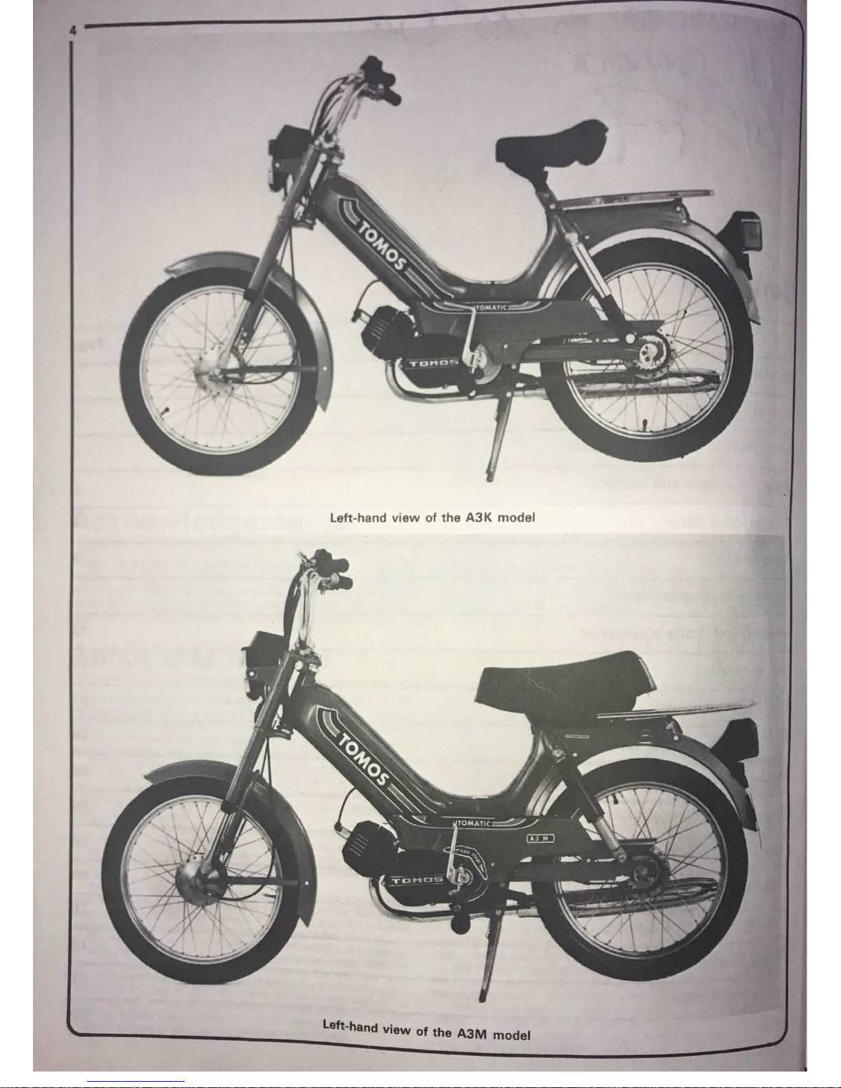
Left-hand
view
of
the
A3K
model
Left-hand
view
of
the
A3M
model
Page 6
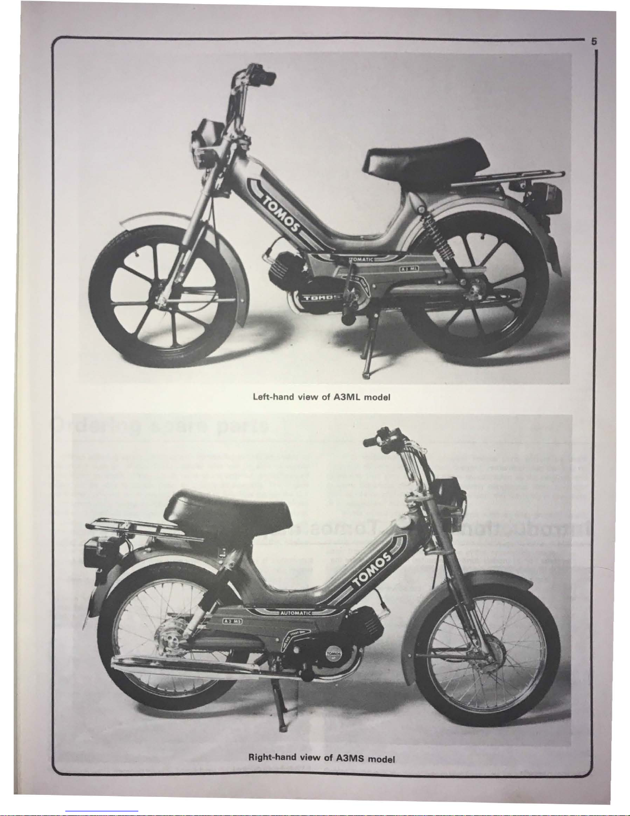
~-------------------------------------------------------------·
Left-hand
view
of
A3ML
model
Right-hand
view
of
A3MS
model
Page 7

Introduction
to
the
Tomos mopeds
The three
Tomos
models currently imported
into
the
UK
share the
same basic chassis and engin
e/
transmission unit.
with
variations in
equipment and accessory
fitments
.
The base
model
of
the range is the
A3K. It
is powered
by
a single-
cylin
der air-cooled
two
-stroke engine driving through a
two
-speed
auto
mat
ic transmission.
The engine/transmission unit is mounted
in
a semi-monocoque
spine frame. fabricated from steel pressings and incorporating the fuel
tank. Fro
nt
suspension is
by
undamped telescop
ic
forks,
whilst
rear
suspension is provided
by a swinging
arm
controlled by coil-spring
suspension
unit
s.
Front and rear
wheels
are
of
the
wire
-spoked type with c
hromium
·
plated steel
rims and
tubed
tyr
es. If·
The
A3MS
Is largely
similar, but
Is distinguished
by
8
~
eel
contained turn signal system, a larger seat and a plated
tubu~
ar
1
5
has
luggage rack. The
A3ML
model Is similar
to
the MS.
1
~
b
lack
redesigned rear suspensi
on
units
with
e>Cposed
springs
and
ma
cast alloy wheels.
_IVl_o
__
d_e_l_d_im
__
e_n_s_io_n_s
__
a_n_d
__
-w_e_i~g~h_t_s
______________
__
Overall
length
.................................................................................... .
1
640
mm
(64
.6 in)
Wheelbase
.......
...
....
...
..................
................
.............................
....
...... .
1080
mm
(42.6 in)
Dry
weight
.....
....
........................
....................
...
.............
...
.................
. .
44
kg
(97
lbs)
Carrying
capacity
.......
...
...................
...
..........
......
........
....................
.. .
1 12.6 kg
(248
lbs)
Page 8
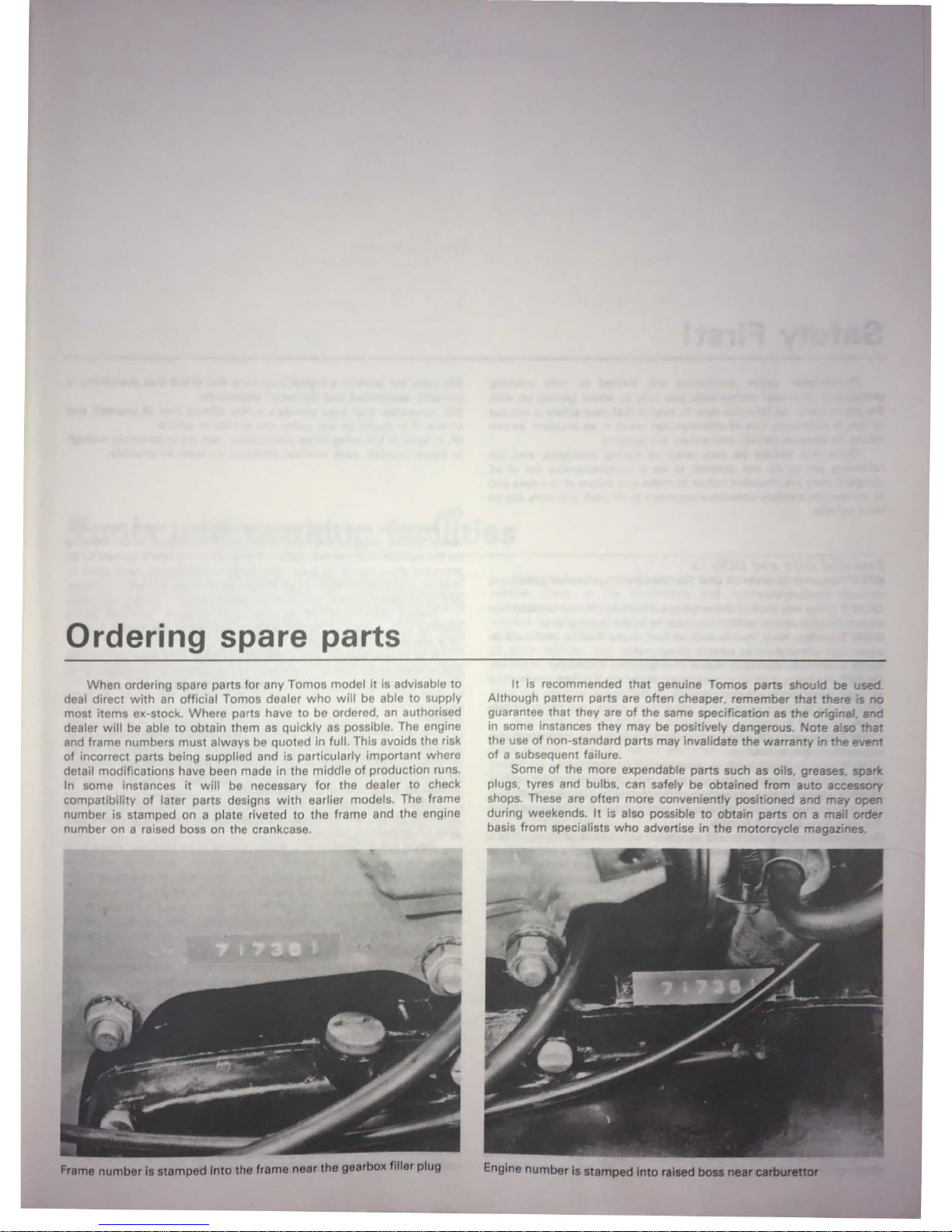
Ordering spare parts
When ordering spare parts for
any
Tomos model
it
is advisable to
deal direct
with
an official Tomos dealer
who
will be able to supply
most items ex-stock. Where parts have to be ordered, an authorised
dealer
will
be able to obtain them
as
quickly
as
possible. The engine
and frame numbers must always be quoted in full. This avoids the risk
of
incorrect parts being supplied and is particularly important where
detail modifications have been made in the middle
of
production runs.
In some instances
it
will be necessary for the dealer to check
compatibility
of
later parts designs
with
earlier models. The frame
number is stamped
on
a plate riveted to the frame and the engine
number on a raised boss on the crankcase
Freme number la
stamped
Into
the
frame
near
the
gearbox filler plug
It
is recommended
that
genuine Tomos parts should
be
used
Although pattern parts are often cheaper, remember
that
there is no
guarantee that they are
of
the same specification as the orig·nal, and
in some instances they
may
be positively dangerous
Note
also
that
the use
of
non-standard parts
may
invalidate the warranty
in
the
event
of
a subsequent failure.
Some
of
the more expendable parts such as oils, greases, spark
plugs, tyres and bulbs, can safely be obtained from auto accessory
shops. These are often more conveniently positioned and may apen
during weekends.
It
is also possible
to
obtain parts
on a mail
order
basis from specialists
who
advertise in the
moto
rcycle magazines.
Page 9

,,
.
Safety First I
r.
, I " .. ' " '
"'''
" "
fl
«I
I h -
"".
" ' " l
lltlll
t 11
ltl
•• ,,,
Wt
l 1~.t11u
"'" 1111 '"''
" ' 1 11111hu••ll•
lh "''" m..
lo "'"'"
'
untt
lll\)
11
11 with
Ill
11 h
It'
ll11l\ll
11
11
1111.tt
l
htt
1
111111
h i
110111
111111
V•l•ll
anl• II( 11
11•
)1 11111
111
11•1..
n\Ott\ Ill • 1
11
1 I\ tlf
11
11
11111111
1
1111 '"""
"
h1
nll
'" ,
ltfn11
1 n• 1
n11
f
fltf\tl
"' \>! lo t\,tl t f!flti
ftl
nl
tt1
n11f11ly
Ill I
111111111
1
1\"'" "'"
"'"
\
II
i;11
""
wny• 111 h 1
1\
1lt1l l 1 c lt
ft
1111
1
n11tl
tll•r
''
""'~'"'
II
'
"""
'' ,,,, "'''
Ill
Ct1t1d ,
,,
It•
fl
I '
'"'
llfltlu
1111h
1t1
ll
•t tll
nil
(111
1
II
••
m Ill
lt
11n11.tntl
1 lllho
tt
h i
'"
"~"
yt111
nw111t1
11
1
11
111
rl•
~ •
n111
f
hl !
Hit
,Jul U
II
11,.
lnl\
I
1llllh
ft)\111
lljlf
llt1n1
h l
ol
nit Wtlt
l\
y11111rttty11
111
1111
I 1\111
""l\11
I
f,
t,ttmtf1tl UOs
""''
OON
' 1 s
DON 'T
1'11<1111
111
" ' 11
1111
11
1111
11111
11
v•H• "'" """'
11 ''"'', ""'"" r1
11ll
l1 l11111lv
h l 1
1\
'0ttt
'' ,.1,t11111
\'
Oii
DON'T ll••l!lt
n11v
"""
or
111
11
ri1111l
1111 "-'""'
"'
'"
""'
""
'" wlt
l11
1" 1
111111
•~•
'"
'" 111
1111 tl\11
1 It I•
~
11ll
t.
l
t111llv
,
u11I
ltl nvoltl
1111111
111
11
Y''"
DON'T
~111h111
1
tml1•
llq11lct
111
11
h
"
~
1111
11
hrnlo.•
t
rt.oltl
111
11111lh11111•i l1y
n
ou
th
O•
nllt1w thttm h i 10
111nl11
1111
yo111
~t.,1
11
DON'T """'"
l
11n
ko 11111
1111
t111~t
It
Is lr1
j11il111111
1t1
l11
1nl
1h
DON'T
;illuw ""Y 81)
1it
u
ll
ur
1110:111ri
to 1111110111 1i11
11111 fl
11u• wltJ•J II
1111
ltA11Jht 11w
11v
holu10 '
u11111011c
8llfJ~
11
11
II
DON'T U
IM!
111
lltt l
11y
11J11
11110111
01 uthc1
tu11I
~
whir h
111rty 1111a11rl1,n11!lu
111ju1y
DON'T
11t1otnp
t tu illt
11
heovv c
u111pu11
1111t wh
ich
11 11
1y IJu b11y1111t1 yo"'
"IJ"llllltv
yot 11ul11
t1111
o
DON'T
1u
' h to
ll11l
1h n
lob
, 01
t11k
11
u11votlllutl t1hu
11
c11111
DON 'T o
ll
uw hllrltun
or
01111110111 111
ur
n1uu11d
1111 u1111tt1111uuct
v11hl
clo.
DON'T
lr1fh1tw
o tyro tu
11
IJ'Oll&uro
obuvo thu rocu
111111
011do
tl
111uxl111u111
.
Aoort hum o
vo11110
11t1l
ny 1hu cnrcnso
1111d
whuol rlrn, In uxtromo
cu11u
11
tho tv•
11
moy lllow o
rr
lorclllly,
DO 0
11
t1u
ru thot th u
n111
chl
110
11 11upp
urt
od
11o
cur o
ly
ut ull tlrnu11. Th
l8
1
11
u
i-..
lnllv
lmpo
1tont
when
tho mnchlnu
11
bluckud
up
tu old whool
or
I
11>.
111
111
ovol,
DO Ink@
1110 when
11ttom1>tlng
to 1lockon o 11tubbu1n
nut
01
bolt.
It
11
ueno111lly
l>otte• to
J)ull
0
11
11 llP!lt1t101, ruthor thon pu11
h, so
lhot
If
11llJ)
1J•Uil
OC
011
you
foll
owoy
hum
tho
rr1ochl1111
rothor
thon
on
to
It.
DO
w
o11
1 ovo 01otootlon when u1l
ng
powor toul
11
such
oa
drill i t1ndor
berr
h
ytlnd111
etc. ' '
DO
u110
11
b111t
lor c1
110n
1 on yu
u1
h1111d1 p1l
or to undortoklng dirty Jobi
It will 01oto t your 1kln lrom lnluotl
on
01 wnll
0
11
moklng
tho
dirt
entlor
to 10
111
ovw 1tftn1wo1d1:
but
m11k
o
11
uro
yuur
horidt1
r n't I f
11
ll1motv
11
o o t
DO
kl!iip
l
ooH
clothing lcuff1, tlo otol
1111d
long holr woll out f
th
of
muvl
11u
rnochonlool uorta.
0
0
way
DO romovo
rl11y
8, w1l1twotch oto,
bol
oro working
011
the
v .
hi 1.
01111o
clollv
thn
oloc
t1l
col 1y1tnm.
0
c o -
DO
kMp vour
work oroo tidy - It
lt1
only t
oo
0111y
to
loll
ov
1
1 1
loll
1v1110
orou11d
.
0
11rt
c
111
DO
ntcor
c18o ooutlo
11.wl11111 cum111oul11y 01Jrlr1•
-•• for r
1 i: "
cm1ov11
or
l11111t1llntl
on.
1111ur
·o tht1t
tho
t111111lo11
I"
n11pll
11d
011d 101
0111
11
d
In
11
00
1111oll
otl
monn
or,
u11lny
11ultoblo toul11
which procludo
tht1
POlll!lblll
of
tho
"ruing o8unnlnu vlolontly. ty
DO
yot
110111001111
to ohook 11orludl
oollv thnt
1111
In
woll, whon workln
11luno
011
tho vehhJllJ
, g
U()
1
llll'(
•J
'll
w•H
~
IJI
11
1•11111,
111
ti•J'
fll'lll',lj
lirl•I r,ll
lJ•)-
lll"J
YIV
, ,11,,
1
,
1ly 11
t1d•H11t1l11d
11
11•1
rl
ul1111r1•1•
I 1tfl'ltWttr•Jt
fl
f,
00
trlflllfllllltfl 111
111
y11
111
V•llil•,lt1'
«i
lilfftily
lflf1J•,l1t 111
111
I~
I
n
l'
N>;.-1
oll1•1t•
II
111
tl•
111li1
•Jll
tttly
Jl'I
Ill, lj•1I lll
JIJl,l/iJ
ll,1
i,tl~'At.
"''
If
'. 1
11
•
rJ'"
' ,,, l
11
ll•
1wl11u
1li•
111
•1
tJ1111,1
1111l•1
r111
,
vou "'"
1111
19,
1
1
,
.,._.~
" ' l
11j11111
yt1111••1l
l ... ,
.,.,, 111<1tll•
,nl l
llf•Jril
l•m
""
f$/i')
f}
.H
V,.,.,•
I+
,
,~,
r 1"'
lt•1
1111
1111
l1•
JJ 111
1111
1l
11J1m 11 11
11 11•11111
1 (
1,1•Jtjl1lln.,
) I•
h#J
"i
~"''l';
~
N•JV'
JI
rlJ•
lll~•t
,
111
l111v11
1111y
~lrt
d
•11
111
1~•1d
fl
llm
'I
1'
tf'IUnd ,
rf~
l
l'/
" r
•HI
11
111 V•J
ltl,,l1J 11
111 11111
rlt1
~
d1J•
H1
11111 •Jtld
lfl'lllj
11
'f)1Jf1o1,j>WJ
11
(;
•1l•11,1rlt.
11I r1l1•11I
1,l11.ul1, l
1y
rw•i 1n1,1:1l
c;1nfT1•
,,11•
•
/)f)Uf'.UN
.J
u '11i/
·"1
't
•1v•1
11
tiv 1111111•
, •1l•i•.
1rl1
,lrv 1
111111
11p
In y11
1Jr
ll•>
dy und.,, t'Arlb'
l/J'
~,-1~
1,1
111 i(j11lt11 lf<
Jll•
ll
Vflf/')11
1, Wlil
1,
h
ltl
!l
1,1Jnf1
n,,tJ
§f);Ji;,t
l•
nlrji
(
i;
l',l
f,+,.
/\l
w11y•1 tflr1r,•1n11111, 1
1111
1 IJ<1ll•JJ
Y 1
1:
irth
(
f,Jrt)Ur\11
)
Ufl
.& !.'!'/•
W•11l-,l1111
•)
II
!Illy
JJltl
I •11 I h•1 fu•
JI
fiYIJl•;m,
1,t
nd
rltrtfjr
rl~
~r/J
I
ill
'I
1t1 " l
11J1 •111t1lt111 01
•1~lt111JNI
II I /
11
1r,11
1111111
111
tl•
1d 110:
11
o
f111;
!Jl!tlnyul1hor
of
a typt
.vJ'.lM.1.-.
~1
1111
11
rt11
tf •ilt
11,1
tl1
,al llrcrri
Ir;
~•iJJI
l1111 11
Jy In th.,
ij!H391'
or
w0ft1):;-,;,
I'
1
t
h111111 N•1v
•11
try tu •111ln
11u
l11
t. '' f
u•1
I m 111.,ctr1
c1I
11,,1
vA
Nl'
K
Fumus
Co
rt11
ln l•rnH
1t1
:m1 h1
1Jhl
y toirl
r.
!lnrJ c
11n quicklv
cau~
uw rt>"
..<;;.,
11
ur10 1111t1 •1v
•m d•J!lth If lntwl•J
rl
10
any
m1tont.
P1Jtr
ol lg1v.krtl
¥"7
//
c1Jrn1J
n 1
1110 thlr1 r.1
1t•111
ury, 0
11
rJ
o th•J V
!lfJOIJr§ from
~ruin
yA-
1i:,
ac
11
0 trlchlo1oothyl•1n"
/\11
v d rol
nlno
or po uring
of
well
vCila
r
./~
uhouhJ
h•1
tlo
no
In
11
W!lll von tll1
J11
id
aroa
.
Whori uolnlJ c
l11a11ln1J
flu
ldlJ and w l
v6ntl
,
rlJad
tM
im!l1.o~J
curi1lullv. Novirr u
110
motorioln from unmarlu.td
co
ntain11r1
-
rhl:Y
r-~
I
ylvo o
ff
pol11unou1i v11puur11.
G'
Novor run
tho
unglno
of a mot
or
vehiclB In
an
encio~
Jf)Y.);
•
111 II
gurnyo. E•
h11u111
fum
o11 contain carbon
m
~
,,,t
"TJ:
otctrom•Jlv
pol1011ou11; If
you
nood
to
run
the
engine
. alw
av10<J
to';:
opo
n olr or ot loo1 t
havo tho roar
of the vehicle out
.;d'l
tnlJ
W(J('r
f/
~
If
vou
aro
fortunato ono
ugh
to
have the u
te
of
an
I
~~~
novor
drain
or pour
petr
ol, and n
ever run
the
engine
.
wniJe
~
.-r.J
11 t1tandlng
ovor
It;
tho
fumo1.
boin
g h
11avier than
air, will
CJ1(Y/.f
In
the
pit
with
po111lblv lethal r111
ult1.
Mains
electrfclty
.,,
..
¢
Whon
u1l
ng
11n
olectrlc
power too
l, ln..,ection
li
ght
:c;ott~
work
s from
tho
m11ln
1. 11lway1 ensure
that
the
app
liance
trfY
e
aJtt,.d
c
onnect11d
to
Ill
plug
and
that. wher11
nece15ary. it is
~oot
and
141
'
(groundodl. Do not u10 1uch
applian
ces
In
damp condiflonJ .
"
-wi
~~
b
·
~ ~
·
ewor11
of creating a 1p
11rk
or applvl
ng
e11
ce11ive
heat
in
fuol or fuol
vap
our.
Ignition
HT
voltage .
parU
iJ
A
1111vore
el11ctrlc shock can
r111ult from
tou
ching
~rt.a·~
(lllllli<i9
tho
Ignition 1y11om, 1u
ch
111 th11
HT
lead
s.
when
the
eng~!
;,,wJa:P'
or bolng c
rankod
, p
ortlcul11rly
If components are
damP or
ed
1
M !ff
1
•
do
foctl
v11. Whore ""
oloctronlc Ignition 1y!ltem 1•
fitt
'
vo
lt8gt
11 much
hlgh11r
ond could
prove
fatal.
Page 10
Tools
and
working
facilities
The first pri
ority
when
undert3king maintenance
or
repa
ir
work
of
any sort
on a motorcycle
is
to
have a clean. dry,
well
-lit
work
ing area.
Wo
rk carried
out
in
peace and
quiet
in
the
well
-ordered atmosph e
re
of
a good
workshop
will
give
more
satisfac
tion
and much
better
results
than can usually
be
achieved in
poor
working
conditions. A good
workshop
must
have a clean
flat
workbench
or
a solidly constructed
table
of convenient
working
height
. The
workb
ench
or
table sho
uld
be
equipped wi
th
a vice
which
has a jaw
openi
ng
of
at
least 4 in (
100
mm). A set
of
jaw
covers
should
be
made
from
soft
metal such as
aluminium
alloy
or
copper. or
from
wood
. These covers will minim
ise
the
marking
or
damaging
of
soft
or
delicate
components
whi
ch
may
be
clamped in
the
vice. Some clean, dry, storage space
will
be required
for
tools, lubricants and
dismantled components. It
will
be
necessary
during a major
overhaul
to
lay
out
engine/gearbox components
for
examination and
to
keep
them
where
they
will
remain undisturbed
for
as long as is necessary.
To
this
end
it
is recommended
that
a supply
of
metal
or
plastic containers
of
suitable size is collected. A supply
of
clean.
lint
-free, rags
for
cleaning purposes and some newspapers,
other
rags,
or
paper
towels
for
mopping
up
spillages should also be
ke
pt. If
working
on
a hard concrete
floor
note
that
both
the
floor
and
one's knees can
be
protected
from
oil spillages and
wear
by
cutting
open a large cardboard
box
and spreading
it
flat
on
the
floo
r under the
machine
or
workbench. This
also
helps
to
provide some
warmth
in
wi
nter
and
to
prevent
the
loss
of
nuts
, washers, and
other
tiny
components
which
have a tendency
to
disappear
when
dropped on
anything
other
than a perfectly
clean,
flat
, surface.
Unfortunately, such
working
conditions
are
not
always available
to
the home mechanic.
When
working
in
poor
conditions
it
is essential
to
take extra ti
me
and care
to
ensure
that
the
components
being
worked
on are
kept
scrupulously clean
and
to
ensure
that
no
components
or
tools are lost
or
damaged.
A
selection
of
good
tools
is a fundamental requirement
for
anyone
cont
e
mplating
the maintenance and repair
of a motor
vehicle. For
the
own
er
who
does
not
possess
any, their
purchase
will
prove a
considerable expense,
offsetting
some
of
the
savings made by
doing
-
it
-yourself.
However
, provided
that
the
tools
purchased are
of
good
quality,
they
will
last
for
many
years and prove an extremely
worthwhile
investment
.
To help
the
average
owner
to
decide
which
tools
are
neede~
to
carry
out
the
various tasks
detailed
in
this
manual,
we
have compiled
three lists
of
tools under
the
following
headings:
Maintenance
and
minor
repair, Repair
and
overhaul, and Specialized. The
newcomer
to
practical mechanics shou ld start
off
with
the simpler
jobs
around the
vehicle. Then, as his confidence and experience
grow
. he can
undertake more
difficult
tasks, buying extra tools as and
when they are
needed.
In
this
way
, a
Maintenanca
and minor
repair
tool
kit can be
built-up
into
a Repair
and
overhaul
tool
kit
over a considerable period
of
time
without
any
major
cash outlays. The experienced
home
me
chanic
will
have a
too
l kit good e
nough
for
most
repa
ir
and overhaul
procedures and
will
add
tools
from the
specialized category
when
he
feels the expense is justified
by
the
amount
of
use these
tools
will
be
put to.
It
is
obv
iously
not
possible
to
cover
the
subject
of
tools
fully
here.
For those
who
wish
to
learn more
about
tools and
their
use
the
re is a
book
ent
itl
ed
How
to
Choose
and
Use
Car Tools availabl e
from
the
publis
hers
of
this
manual.
Although
, as
its
title
implies,
this
publi
cation
is directed at car
owners. the
information
given is equally applicable
to
mo
torcycle owners.
It
also provides
an
introduction
to
basic
workshop
practice
whi
ch
will
be
of
int
erest
to a home
mechanic worki
ng
on
any
type
of
motor
vehicle.
As
a general rule.
it
is
bett
er
to
buy
the
more
expensive, good
quality
tool
s. Given reasonable use,
such
tools
will
last
for
a very long
time
, whereas
the
cheaper,
poor
quality,
item
will
wear
out
faster and
need
to
be renewed
more
often, thus
nullifying
the
orig
inal saving.
There
is
also
the
risk
of a poor
quality
tool
breaking
while
in use.
causing
personal injury
or
expensive damage
to the
component
being
worked
on.
It
should be
noted, however, that
many
car
accessory
shops and
the
large
department
stores sell
tools
of
reasonable quality
at
competitive
prices. The best example
of
this
is found
with socket
sets,
where
a mediu
m-priced
socket set wi
ll
be
quite
adequate for the
home owner
and
yet
prove less expensi
ve
than a selecti
on
of
individual
sockets and accessories.
This
is because individual pieces are usually
only available
from
expensive,
top
quality
. ranges and
whilst they are
undeniably good, it should be remembered
that
they
are intended
for
professional use.
The basis
of
any
toolk
it is a
set
of
spanners.
While
open-ended
spanners w i
th
the
ir
slim
jaws.
are useful
for worki
ng
on
awkwa
rdly-
positioned
nuts, ring
spanners have advantages
in
that
they
grip the
nut
far
more
positively. There is less risk
of
the
spanner slippi
ng
off the
nut
and
damaging it,
for
this
reason alone ring spanners are
to
be
~referred
.
Ideally,
the
home
mechanic
should acquire a set
of
each.
but
if
expense rules this
out
a set
of combination
spanners (open-ended
at
one end and
with a ring
of
the
same
size at
the other) will provide a
good
compromise. Another
item
which
is
so
useful
it
should be
Page 11

10
Tools
and
wortting
facilities
considered an essential
requ
irement
f~
an
~e
mecha
c is a set
of
soc;ket soanners
These
a
re
ava~able
m _a van
ety
of
d
ri
e size
It
Is
ecommended
th
at
the
f-i
nch
dm
<e
type
is
purchased to
beg
m
th
as
1
linough bul er and
mor
e e
x:pe
nsive than the !
-inc
h
type
,
the
larger
:i
ze
rs far
moie
common and will accept. a greater variety
of
torque
wrenchel
e~en:sion
pi
eces a
od
soclt
et size
s. The
socket
set
should
compnlloC
sockets of sizes
between 8 and
24
~m
.
a re ersible ratch
et
d
. an extension bar
of
about 10 i
nch
es m length. a spark plug
mre. _
_.
I I
'.
0
socket wi
th
a rubber inse
rt
. a
•ou a un
versa
JOm
t. ther
attachments
can
be
added
to
the set
at
a l
ater
date
.
Maintenance
and
minor
repair
tool
kit
Sf!f
of
spannf!
rS
8 -
24
mm
Sf!t
of
sockets
and
attachments
Spark
plug
spanner wi
th
rubber insert
-
10
. 1 2. or
14
mm
as appropn'ate
Adjustab
le spanner
c-spanner/pin
spanner
Toroue wrench (
same
size dri
ve
as
sockets
}
Set
of
scre
wdrivttrs (flat
blade}
Set of scrtt
wdrivttrs
(c
ross-head}
Se
t of
All
en lceys 4 -
10
mm
Im
pact scre
wdr
iver
and
bits
B
all pein hammttr - 2
lb
Hacksaw (junior}
Self-l
ocki
ng plittrs -
Mole gri
ps
or vice grips
Pliers - c
ombination
Pliers - nttedle nose
Wirt! brush (
small
}
S
oft-br
istlttd brush
Tyre
pum
p
Tyre
prtt
ss
ure gaugtt
Tyre
tread
depth
gauge
O
il
can
F
in
e emery
cloth
Funn
el (medium
size)
Drip
tr
ay
Set of feeler gauges
Strobe timi
ng light
Continuity tester
(dry
battery
and
bulb)
Solderi
ng iron
and
solder
Wi
re
stripper
or
craft
knife
PVC insulating tape
As
sortment
of
split
pins. nut
s.
bolts. and washers
Repair
and
overhaul
toolkit
The tools in this list are virtually essential for anyone undertaking
major repairs
to
a motorcycle and are additional
to
the tools listed
above. Concerning
Tone
driver
bits. Tone screw
s are enc
ount
ered on
some of the more modern machines where their use is res
tri
cted
to
fastening certain components inside the engine/gearbox
unit. It
is
therefore recommended
that
if
Tone
bits cannot be borr
owed
from
a
local
dealer. they are purchased individually as
the
need arises. They
are not in regular use
in
the
motor trade and
will therefore on
ly
be
:t\1!>;1-,.h
ln
:n
..,_
....
....
: ... 1
:-• •--
• - •
Will!
brush fla
rge
J
Soft ·re
brush
(similar to thos
e used for
cleaning
sued
e
shoes}
S
hee
r of
pla
te glass
Hac
ksaw
(/11rgtt}
Valve
grinding tool
Valve g
rind
ing compound (coarse a
nd fine}
St
ud
extract
or
set
(E-Z
out}
Specialized
tools
Th
is
is
not
a list
of
the
tools
mode
by
the ma chine's manufactu
rer
to
carry o
ut
a specific task on a
limit
ed range
of
models. Occasional
references are
ma
de
to such tools in the text
of
this manual ond. In
general. an alternative met
hod
of carrying o
ut
the task w
itho
ut
tho
manufacturer's t
oo
l is given where possible. Tho tools me
nti
oned In
th
is list are those
whi
ch ero
not
used regularly and are oxpenslvo to
buy
in view of their infrequ e
nt use. Wh
ere this
is
the case it may
be
possible
to
hire or bor
row
the tools
against a deposit from a local
dea ler
or
tool hire shop. An alternative is for a group of friends
or
a
motor
cycle club to join in the purchase.
Piston ri
ng
comp
ressor
U111versal
beari
ng pull
er
Cylinder bore h
oning attachment (for
elecrric
drill)
M
icror
net
er
set
Vernier calipers
Dial gauge set
Cylinder
co
mpression gau
ge
Vacuum
gauge set
Mulrimeter
Dw
ell merer/racho
met
er
Care
and
maintenance
of
tools
Whatever the quali
ty
of the tools
pur
chased, they
will
last much
longer if cared for.
Th
is means in practice ensuring
that a too
l Is used
for its
in
tended purpose:
for
example screwdrivers should
not
be used
as
a substitut
e for a centre
pun
ch.
or
as
chisels. Always remove dirt or
grease and any metal partic
les but
remember
that a light
film
of oil will
preve
nt rusting if the tool
s are infrequently used. The common tools
can be kept together in a large box
or
tray
but the mo
re
delicate. and
more expensive,
items
shou ld be stored separately where they
cann
ot
be damaged. When a
tool
is damaged or
worn
out
, be sure to renew
it
immediately.
It
is false eco
nomy
to continue
to use a
worn
spanner
or
scre
wdr
iver
whi
ch may sl
ip
and cause expensive damage to the
component be
ing wo
rked on.
Fastening
systems
Fastener
s.
basica
lly
, are
nut
s, bol
ts
and screws used
to
hold two
or
more p
art
s together. There are a
few thi
ngs
to
keep in mind when
working
with
fasteners.
Almost
all
of
them
use a locking
device of
som
e type;
eithe
r a lock was
her
. lock
nut
, locking
tab
or thread
adhesive. All
th
readed fasteners should be clean. straight. have
un
dama
ged threads and
undama
ged co rners on the hexagon h
ead
Page 12
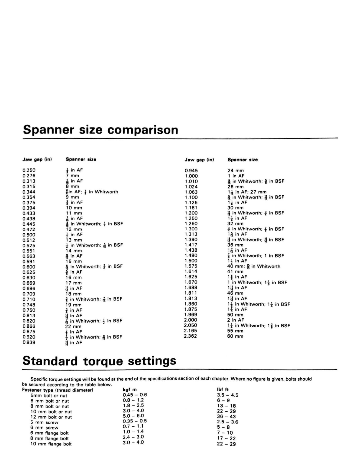
Spanner
size comparison
Jew
gap
(in)
0.
250
0.
276
0.
313
0.
315
0.
344
0.
354
0.
375
0.
394
0.
433
0.
438
0.
445
0.
472
0.
500
0.
512
0.
525
0.551
0.
563
0.591
0.
600
0.625
0.
630
0.
669
0.
686
0.
709
0.
710
0.
748
0.
750
0.
813
0.
820
0.
866
0.
875
0.
920
0.
938
Spenner
eize
t in AF
7
mm
i\
in
AF
8
mm
}lin
AF; t in
Whitworth
9
mm
i In AF
10
mm
11
mm
4
in
AF
.\
in
Whitworth
; t in BSF
12
mm
tin
AF
13
mm
t in
Whitworth
:
t\
in BSF
14
mm
i\
in AF
15
mm
i in
Whitworth
: i in BSF
i in AF
16
mm
17
mm
ij
in AF
18
mm
i
in
Whitworth
: 4 in BSF
i9
mm
tin
AF
Ii in AF
4 in
Whitworth
; t
in
BSF
22
mm
tin
AF
t in
Whitworth
; i\ in BSF
II
in AF
Standard
torque
settings
Jaw
gap
(in)
0.
945
1.
000
1.
010
1.
024
1.
063
1.100
1.
125
1 .181
1.
200
1.250
i .
260
1.
300
i .
3i3
i .
390
1.
417
1.
438
i .
480
1.
500
i .
575
i .
6i4
i .
625
1.670
1.688
i .8
ii
i .
813
i .
860
1.875
i .
969
2.
000
2.
050
2.i65
2.
362
Spanner
elze
24
mm
1 in AF
A in
Whitworth
; i In BSF
26
mm
1~
in AF;
27
mm
A in
Whitworth
;
ij
in BSF
1-f
in
AF
30
mm
ij
in
Whitworth
; t
in
BSF
lt
in AF
32
mm
t in
Whitworth
; i in BSF
11\
in
AF
Ji
in Whi
tworth
;
II
in BSF
36
mm
i4 in AF
t in
Whitworth
; i in BSF
1t
in AF
40
mm
: Ii
in
Whitworth
4i
mm
it
in AF
i in
Whitworth; it
in
BSF
1ij in AF
46
mm
i!j
in
AF
it
in
Whitworth; if
in
BSF
it
in
AF
50
mm
2 in AF
ii
in
Whitworth; ii
in
BSF
55
mm
60
mm
Specific torque settings
will
be found at
the
end
of
the specifications section
of
each chapter. Where
no
figure is given.
bolts
should
be
secured according
to
the
table
below
.
Fastener
type
(thread diameter)
5mm
bolt
or
nut
6
mm
bolt
or
nut
8
mm
bolt
or
nut
10
mm
bolt
or
nut
12
mm
bolt
or
nut
5
mm
screw
6
mm
screw
6
mm
flange
bolt
8
mm
flange
bolt
1 0
mm
flange
bolt
kgf
m
0.
45
- 0.6
0.8
- 1.2
1.8 -2.5
3.0 - 4.0
5.0
- 6.0
0
.3
5 - 0.5
0.7
-
i.
i
i .0 - i .4
2.4 - 3.0
3.0
- 4.0
lbf
ft
3.5 -
4.5
6 - 9
i3 -i0
22 -29
36 -43
2.5 - 3.6
5 - 8
7 -
io
i7 -22
22
-
29
Page 13
r
,~
Choosing and fitting accessories
The range
of
accessories available
to
the
modern
motorcyclist
is
almost as varied and
bewildering
11
the
range
of
motorcycles
. This
Sectio
n is intended
to
help
the
owner
in
choosing
the
correct
equlpment for his needs
and
to
avoid some
of
the
mistakes
made
by
many riders
when
adding accessories
to
their
machines. It
will be
evident that
the
Section can
only
cover the subject
in
the
most
general
terms and so
It
is
recommended that
the
owner
. havi
ng
decided
that
he wants
to
fit.
for
example. a luggage rack
or
carrier. seeks t
he
adv
ice
of several local deelers end
the
owners
of
similar
machin
es. This
will
gi
ve
a good idea
of
what
makes
of
carrier are easily available . a
nd
at
what price. Talking
to
other
owners
will
give
some
insight
into
the
drawbacks or
good
points
of
any one make. A
walk
round
the
motorcycles
in
car
parks
or
outside a dealer
will
often
reveal the same
sort
of
information.
The first priority
when
choosing accessories is
to
assess exactly
what
one needs.
It is, for example, pointless
to
buy a large
heavy-duty
carrier
which
is designed
to
take
the
weight
of
fully laden panniers and
topbox when all you need
is
a place
to
strap
on
a set
of
waterproofs
and a lunchbox when
going
to
work.
Many
accessory manufacturers
have ranges
of
equipment
to
cater for the individual needs
of
different
riders and
this
point
should
be
borne
in
mind
when
looking
through
a
dealer's catalogues. Having decided exactly
what
is
required and the
use
to
which
the accessories are
going
to
be
put.
the
owner
will
need
a
few
hints
on
what
to
look
for
when
making
the
final choice. To
this
encl
the Section
is
now
sub-divided
to
cover
the
more
popular
accessories
fitted. Note
that
it
is
in
no
way
a customizing
guide, but
merely seeks
to
outline
the
practical considerations
to
be taken
into
account
when
adding aftermarket equipment
to a motorcy
cle.
Fairings
and
windscreens
A fairing
is
possibly
the
single.
most
expensive, aftermarket
item
to
be fitted
to
any motorcycle and, therefore, requires
the
most
thought before purchase. Fairings can be divided
into
two
main
groups: front fork mounted handlebar fairings and
winds
creens, and
frame mounted fairings.
The first group, the
front
fork
mounted fairings, are
becoming
far
more popular than was once the case, as they offer several advantages
over
the
second group. Front fork mounted fairings generally are much
easier and quicker
t?
fit,
involve less modification
to
the motorcycle,
do
not
as a rule restrict the steering lock,
permit a wider
selection
of
handlebar styles
to
be used, and
offer
adequate protection
for
much
less money than the frame mounted type. They are also
lighter
can be
swapped easily
~etween
different motorcycles, and are availa0ble
in
a
much greater variety
of
styles. Their main disadvantages are
that
they
do
not
offer
as much weather protection .as
the
frame
mounted
types,
rarely offer any storage space, and,
1f
poorly fitted
or
naturally
incompatible, can have an adverse effect
on
the stability
of
the
motorcycle.
The second group,
the
frame mounted fairings, are secured
so
rigidly
to
the
main
frame
of
the
motorcycle that they can offer
8
substantial
amount
of
protection
to
motorcycle and rider
in
the
event
of
a crash. They
~ffer
a.lmost
comp~ete
protectlo~
from
the
weather
and,
if
double-skinned
in
construction, can provide a great deal
of
useful storage space. The
'?~ling
of. peace, quiet and complete
relaxation encountered
when
riding behind a good full fairing has
to
be
experienced
to
be believed. For this reason full fairings are considered
essential
by
most
to
·
11
uring motorcyclists and by many people
who
ride
: year
roun~
.
The main. disadvantages
of
this type are that fitting can
ake a
long
time. often
involving removal
or
modification
of
standard
motor
cycle components, they restrict the steering
lo.ck
and they can
add
up
to
about
40
lb
to
the weight
of
the machine They do
not
usually affect the stability
of
the machine
to
any great
e~ent
once the
front tyre pressure and suspension have been adi·usted t
f
. o compensate
or
the
e~tra
w?1ght, but can be affected
by
sidewinds.
The.
f1~st
thing
to
look
!?r
when
purchasing a fairing is the quality
of
the fittings. A
good
famng
will
have strong, substantial brackets
c.onstructed from heavy-gauge tubing; the brackets must be shaped
to
fit the frame
or
forks evenly so that the minimum
of
stress is imposed
on the assembly
when
it
is bolted
down
. The brackets should
be
properly painted
or
finished - a nylon coating being the favourite
of
the
better manufacturers - the nuts and
bolts
provided should
be
of
the
same thread a
nd
size standard as
is
used
on
the
motorcycle and
be
properly plated. Look also
for
shakeproof locking nuts or locking
washers
to
ensure
that
everything remains securely tightened down.
The fairing shell
is
generally made from one
of
two
materials:
fibreglass
or
ABS
plastic. Both have their advantages
and
disadvantages,
but
the
main
consideration
for
the owner is that
fibreglass
is
much easier
to
repair
in
the
event
of
damage occurring
to
the fairing.
Whiche
ver material
is
used, check that
it
is properly
finished inside as
well
as out,
that
the
edges are protected by
beading
and that
the
fairing shell
is
insulated from vibration by the
use
of
rubber
grommets
at
all
mounting
points
. Also be careful
to
check
that
the windscreen is retained
by
plastic
bolts
which
will
snap
on
impact
so that
the
windscreen
will
break
away
and
not
cause personal i
njury
in
the event
of
an
accident.
Having purchased your fairing
or
windscreen, read the
manufac
-
tur
er's
fitting
instructions very carefully and check that you
have
all
the
necessary brackets and
fittings
. Ensure
that
the
mounting brackets
are
located correctly and
bolted
down
securely.
Note
that
some
manufac
-
turers use hose clamps
to
retain
the
mounting brackets;
these
should
be
dis
carded as
they
are convenient
to
use
but
not
strong
enough
for
the task. Stronger clamps should
be
substituted; car
exhaust
pipe
clamps
of
suitable size
would
be
a good alternative.
Ensure
that
the
front
forks can turn
through
the
full steering lock available wit
hou
t
fouling
the
fairing.
With
many
types
of
frame-mounted fairing the
handlebars
will
have
to
be
altered
or
a different type fitted
and
the
steering lock
will
be restricted
by
stops provided
with
the
fittings
.
A
l~
check
that
the
fairing does
not
foul
the
front
wheel
or
mudguard
.
in
any steering position
under
full
fork
compression. Re-route
anv
cabl~s
.
brake pipes
or
electri~I
wiring
which
may
snag
on
the fairin.g
and
ta
~
great
care
to
protect
all electrical connections, using insulating tape.
the
manufacturer's instructions are
followed
carefully
at
every
stage
"
1
.
0
be
h t
hydrau
1c
serious problems should
be
encountered. Remem r t . 8 d
and
pipes
that
have been
dis
connected
must
be
carefully .re-
t1ghten
e
the
hydraulic system purged
of
air
bubbles
by
bleeding.
k.
a
Two
things
will
become immediately apparent when .
ta
~n~he
motorcycle
on
the
road
for
the
first
time
with
a fairing - the
ftrs~
/:;nd
tendency
to
underestimate
the
road speed because
of
the
lack
.1 ne
pressure
on
the
body. This
must
be very carefully watched unti
~ng
has
grown
accustomed
to
riding behind
the
fairing. The
second 1 t>ut
is the alarming increase
in
engine noise
which
is an
u~fortu
nate
and
in
evitable by-product
of
fitting
any
type
of
fairing
or w1.
ndscreen.ases
is
caused
by
normal engine noise being reflected. and in
some
c
amplified,
by
the
flat
surface
of
the
fairing.
Page 14

Choosing
and
fitting
accessori•
13
Luggage racks
or
carriers
Carriers are possibly
the
commonest item
to
be
fitted
to
modem
motorcycles. They vary enonnousty
in
size. carrying capacity, and
durability.
When
selecting a carrier. always loolt for one which Is made
specifically
for
your machine and
which
is
bolted
on
with
as
few
separate brackets as poasible. The universal-type carrier,
with
it.a
man
of
brackets and adaptor pieces.
will
generally prove
too
weak
to
be
of
any real use. A good carrier should
bolt
to
the main frame . generally
using the
two
suspension
unit
top
mountings and a mudguaro
mounting
bolt
as attachment points. and have
its
luggage platform as
low
and
as
far forward as possible
to
minimise the effect
of
any load
on
the machine's stability. Look for good
quality
, heavy gauge tubing.
good
welding and good finish. Also ensure that the carrier does
not
prevent opening
of
the seat. sidepanels
or
tail compartment. as
appropriate. When using
a carrier.
be
very careful
not
to
overload it.
Excessive
weight
placed so high and so far
to
the rear
of
any
motorcycle
will
have an advenie effect
on
the machine·s steering and
stability.
Luggage
Motorcycle luggage can
be
grouped under
two
headings: soft and
hard. Both types are available
in
many
sizes and styles and have
advantages and disadvantages
in
use.
Soft luggage is
now
becoming very popular because
of
its lower
cost and its
versatility.
Whether
in
the
form
of
tankbags, panniers.
or
strap-on bags. soft luggage requires in general no brackets and no
modification
to
the motorcycle. Equipment can be swapped easily
from one motorcycle
to
another and can be
fitted
and removed in
seconds.
Awkwardly
shaped loads can easily be carried. The disadvan-
tages
of
soft luggage are
that
the contents cannot be secure against
the
casual
thief
. very
little
protection
is afforded in the event
of
a crash.
and
waterproofing is generally
poor
. Also.
In
the case
of
panniers.
carrying capacity is restricted
to
approximately 1 O lb. although this
amount
will
vary considerably depending on the manufacturer·s
recommendation.
When
purchasing soft luggage. look for good quality
material. generally vinyl
or
nylon,
with
strong. well-stitched
attachment points.
It
is always useful
to
have separate pockets.
especially
on tank bags,
for
items
which
will
be needed on the journey.
When purchasing a tank
bag, look
for
one which has a separate.
well-
padded, base. This
will
protect
the tank·s paintwork and permit easy
access
to
the
filler
cap
at
petrol stations.
Hard
luggage is confined
to
two
types: panniers, and top boxes
or
tail trunks.
Most
hard luggage manufacturers produce matching sets
of
these items.
the
basis
of
which
is generally
that
manufacturer's own
heavy-duty
luggage rack. Variations on this theme occur in the form
of
separate frames for the
better
quality panniers. fixed
or
quicklydetachable luggage, and in size and carrying capacity. Hard luggage
offers a reasonable degree
of
security against
theft
and good
protection against
weather
and accident damage. Carrying capacity is
greater than
that
of
soft
luggage, around 1 5 -
20
lb
in the case
of
panniers, although top boxes should never
be
loaded
as
much as their
apparent capacity
might
imply
. A
top
box should
only
be used for
lightweight items. because one
that
is heavily laden can have a serious
effect on the
stability
of
the
machine. When purchasing hard luggage
look
for the same good points as mentioned
under
fairings and
windscreens.
ie
good
quality
mounting
brackets and
fittings
, and
well-
finished fibreglass
or
ABS
plastic cases. Again as
with
fairings, always
purchase luggage made specifically
for
your motorcycle, using as
few
separate brackets as possible,
to
ensure
that
everything remains
securely bolted
in
place.
When
fitting
hard luggage. be careful
to
check
that the rear suspension and brake operation
will
not
be impaired in
any
way and remember
that
many pannier
kits
require re-siting
of
the
indicators. Remember
also
that
a non-standard exhaust system may
make fitting
extremely difficult.
Handlebars
The occupation
of
fitting
alternative types
of
handlebar is
extremely popular
with
modern motorcyclists,
whose
motives
may
vary
from the purely practical. wishing
to
improve the
comfort
of
their
machines.
to
the purely aesthetic, where form Is
more
important than
function. Whatever the reason, there are several considerations
to
be
borne in
mind
when changing
the
handlebars
of
your machine.
If
fitting
lower bars check carefully
that
the
switches and cables
do
not
foul the
Petrol
tank
on full lock and
that
the surplus length
of
cable. brake pipe,
and
electrical
wiring
are smoothly and
tidily
disposed of. Avoid
tight
kinks In cable or brak.e pipes which
will
produce
stiff
cont1ols
or
the
pnimature and disastrous failure
of
an
overstrened
component.
If
necessary. remove the petrol tank and re-route the cable from the
engln gearbox
unit
upwaros. ensuri
ng
smooth gentle curves are
produced.
In
extreme cases.
it
will
be
neceuary
to
purchase a shorter
brake pipe
to
overcome this problem.
In
the c11e
of
higher handlebars
than standard
it
will
almost certainly be
necesury
to
purchase
extended cables and brake pipes. Fortunately.
many
standard
motorcy
-
cles
have a custom version which
will
be equipped
with
higher
handlebars and . therefore. factory-
built
extended components
will
be
available from your local dealer.
It
Is
not
usually necessary
to
extend
electrical
wiring
, as switch clusters may be used on several different
motorcycles. some being custom
versions. This point should be borne
in
mind however
when
fitting extremely high
or
wide handlebars.
When fitting different
types
of
handlebar. ensure that the
mounting
clamps are correctly tightened
to
the manufacturer
's
speci -
fications and
that
cables and
wiring
.
111
previously mentioned. have
smooth easy runs and
do
not
snag
on
any part
of
the
motorcycle
throughout the full steering lock. Ensure that the fluid level
In
the
front
brake master cylinder remains level
to
avoid any chance
of
air
entering
the
hy
draulic system. Also check
that
the
cabl111
are adjusted correctly
and that all handlebar controls operate correctly and can
be
easily
reached when riding.
Electrical equipment
The vast range
of
electrical equipment available
to
motorcyclists
is
so large and so diverse that
only the
most
general outline
can
be
given
here. Electrical accessories very from electric ignition
kits
fitted
to
replace contact breaker points.
to
additional lighting
at
the
front
and
rear. more
powerful horns. various instruments and gauges. clocks.
anti-theft systems. heated clothing.
CB
radios, radio-cassette players.
and intercom systems.
to
name
but a few
of
the more
popular
items
of
equipment.
As
will
be evident. it
would
require a separate manual
to
cover
this
subject alone and
this
section is therefore restricted
to
outlining a few
basic rules which m·Jst be borne
in
mind
when
fitting
electrical
equipment. The first consideration is
whether
your
machine's electrical
system has enough reserve capacity
to
cope
with
the
added
demand
of
the accessories you wish
to
fit
. The motorcycle·s manufacturer
or
importer should be able
to
furnish
this
sort
of
information
and
may
also
be
able
to
offer advice on uprating
the
electrical system. Failing this.
a good dealer
or
the accessory manufacturer may be able
to
help.
In
some cases. more powerful generator components
may
be
available.
perhaps from another
motorcycle
in
the
manufacturer's range. The
second consideration is the
legal requirements
in
force
in
your area.
The
local police may be prepared
to
help
with
this
point
. In the
UK
for
example. there are strict regulations governing the position and use
of
auxiliary riding lamps and
fog
lamps.
When
fitting
electrical equipment always disconnect
the
battery
first
to
prevent the risk
of
a short-circuit, and
be
careful
to
ensure
that
all connections are properly made and
that
they are
waterproof
.
Remember
that
many
electrical accessories are designed primarily
for
use in cars and
that
they cannot easily withstand the ellposure
to
vibration and
to
the
weather. Delicate components
must
be rubber-
mounted
to
insulate them from vibration, and sealed carefully
to
prevent the entry
of
rainwater and dirt. Be careful
to
follow
exactly the
accessory manufacturer's instructions
in
conjunction
with
the
wiring
diagram
at
the
back
of
this manual.
Accessories - general
Accessories
fitted
to
your motorcycle
will
rapidly deteriorate
if
not
cared
for
. Regular washing and polishing
will
maintain
the
finish and
will
provide an
opportunity
to
check
that
all mounting
bolts
and nuts
are securely fastened. Any signs
of
chafing
or
wear
should
be
watched
for. and the cause cured as soon as possible before serious damage
occurs.
As a general rule.
do
not
expect the re-sale value
of
your
motorcycle
to
increase
by
an amount proportional
to
the amount
of
money and effort
put
into
fitting
accessories.
It
is
usually the case
that
an
absolutely standard motorcycle
will
sell more easily
at a better
price
than one
t~at
has been modified.
If
you are
in
the habit
of
exchanging
your
~ach1.ne
for
another
at
frequent intervals. this
factor
should
be
borne
'"
mind
to
avoid loss
of
money.
Page 15
Fault diagnosis
In
t 1
oduet
lon
Engine does
not
start
when
tumed
over
No
hJel
flow
to
c&rt>u
et10f
Fuel
not
ra.ching
cy11~r
_
··-------
Eng
ine
flooding
-----~-------
No
spa!1( at
plug
------····-
W
eak
5011'\
at plug. -····--
·-··-·--------
Compression
low
.......
·····-···---
·--·
_____
--·--
Engine stalls afrer starting
2
3
•
5
6
7
General causes ....
..
.. . ..........
.
. ...
-····--
·---···--···-·-·····
8
Poor
running
at
idle
and
low
speed
Weak
spark
at
plug
or
errat
ic
flri
ng
.... .
....
-··········-····················. 9
Fue air m
hc
ture
incorrect ........
........
.................................... -............ 1 O
Compr
ession
low
........
..................................................................... ....... 1 1
Acceleration
poor
General causes ................................................ ..... ....................
.......
........ 12
Poor
running
or
lack
of
power
at
high
speeds
Weak
spark
at
plug
or
erratic
firing ..........
........................................
...
13
FueVair
mixture
incorrect ...............................
...
.....................................
14
Compre.ssion
low
...... ...
.. . ..
... .... . .
.. ... ... .................
....
.. ..
.. ..
.. ........
...
.........
...
. 1 5
Knocking
or
pinking
General causes .................. ......
....................... ........
...
..........
...
...
.............
..
1 6
Overheating
F
iri
ng
incorrect ............................................................... · ·
··
·· ....
····
··
..
·· ·
.. ····
FueVair mixture incorrect ...................................................................... .
lubrication
inadequate ..........................................................................
..
Miscellaneous causes ............................................................................. .
1
Introduction
17
18
19
20
This Section provides an easy reference-guide
to
the more
common ailments
tliat
are likely
to
afflict
your
machine. Obviously, the
opportunities are almost limitless for
faults
to
occur
as a result
of
obscure failures. and
to
try
and cover all eventualities
would
require a
book. Indeed. a number have been
written
on
the
subject.
Successful fault diagnosis
is
not
a mysterious 'black art"
but
the
application
of a little
knowledge combined
with
a systematic and
logical approach
to
the problem . Approach any fault diagnosis
by
first
accurately identifying
the
symptom and then checking through
the
list
of
possibile causes, starting
with
the simplest
or
most
obvious and
progressing in stages
to
the
most complex. Take nothing
for
granted,
but
above all apply liberal quantities
of
common sense.
The main symptom
of
a fault
is
given in the
text
as a majo
r
heading below which are listed, as Sections headings,
the
various
systems or areas which may contain the fault. Details
of
each possible
cause for a fault and the remedial action
to
be taken are given, in brief,
in the paragraphs below each Section heading . Further information
should be sought in the relevant Chapter.
Engine does
not
start when turned over
2
No
fuel
flow
to
carburettor
• Fuel tank
empty
or level too
low
. Check
that
the tap Is turned
to
·
on·
or
'Reserve' position
as
required.
If
In doubt. remove the fuel feed
Abnormal
engine noise
Knocking
01
pinli.lng ................................................................................
21
Piston slap
01
rattling
from
cylinder ..................................................
..
22
Other noises ..... . ...........
..
....
.......
...................
....
....
..............
................... 23
Abnormal
transmission noise
Transmission noise ..........................................
........................................ 24
Exhaust smokes excessively
Wh
it blue smoke (caused by
oil
burningl ...
....
.................
...
..............
25
Black
smo
ke
(caused
by
over-rich mixture) .................................... .
..
26
P?or . han<!ling ,
o_r
road holding
Directional instab1hty ...............................................................................
27
Steering bins to le
ft
or
right
......
...................
.........................................
28
Handlebar vibrates or oscillates ............................................................
29
Poor fro
nt
fork performance ..................................... .............................
30
Front
fork judder when braking
...
....................................
....
.................
31
Poor rear suspension performance
....................................................... 32
Abnormal
frame
and
suspension noise
Fr
ont
end noise
...
............
...
......................................................................
33
Rear suspension noise .............................................. .............................. 34
Brake problems
Brakes are spongy
or
ineffective ........................................
....
........
......
35
Brake drag ...........
...
...................................................................................
36
Brake lever or pedal pulsates
in
operation ........
....
.............................
37
Drum brake noise ............................................
......................................... 38
Brake induced fork judder .................................................................
.....
39
Electrical problems
Circuit failure .....................................................................................
........
40
Bulbs
blowing
repeatedly .......................................................................
41
pipe
at
the carburettor end and check
that
fuel runs from pipe
when
the tap
is
turned on.
e Tank filler cap
vent
obstructed. This can prevent fuel from
flowing
into
the carbur
ettor
float
bowl
bcause air
cannot
enter the fuel
tank
to
replace it. The problem
is
more likely
to
appear when the
machine is
being ridden. Check
by
listening close
to
the
filler
cap and
releasing
it.
A hissing noise indicates
that
a blockage
is
present. Remove th.e
~a
p
and clear the
vent
hole
with
wire
or
by
using an air line from
the
insid
e
of
the
cap
. .
•
Fu
el tap
or
filter
blocked. Blockage may be
due
to acc
umulation
°1
rust
or
paint flakes
from
the tank's inner surface
or
of
foreign
matte
r
from
contaminated
fuel. Remove
the
tap and clean
it
and
the
filter.
look
also
for
water
droplets
in
the fuel. .
1
• Fuel line blocked. Blockage
of
the
fuel line is more
likely_
to
resu
1
from a kink
in
the
line rather than the accumulation
of
debris.
3
Fuel
not
reaching
cylinder
Page 16
feuh
diagnosis
16
fuel tank
by~pas
smg
the
filter
system
or
to
gumming
up
as de
bed
in paragraph 1. Water droplets in the fuel
al~
ieu aod
pa
ssages. The carburettor should
be
d1sman
ed
f
Of
cl
an.ng
e Fuel level t
oo
low
. The fuel level
tn
the float cham
bet' is
COfl
rol'
ed
by
float height. The fuel level
may
i
nereau
with
wea1
or
dam
ege but
w
ill
never reduce. thus a l
ow
fue
l level i1 an inherent
rath r th
an
develop
in
g condition. Checll
the
flo
at
hei
ght. renewing
the float
or
needle if required.
e Oil b
locuge
in
fue
l system
or carb
ure
llor (pe
tro
il
lub11cated
engines
only
).
May ari
se when
the
machine has been
par\ed
for long
periods
and
the
re&iduel
petr
ol
has
evaporated To rectrfy, dlsmantle
and clean the carbure
ll
or and tap. flush the
tanlo:
and fill
with
fresh
petroil
mh1ed
in the
correct proportions. Th is probl
em
can be avoi
ded
by
running the float
bowl
dry
before the machine is stored for l
ong
periods. Do not
attempt
to
use fuel which has bec
ome
sta
le
4 Engine
nooding
e Float valve needle worn
or
stuck
open
A piece
of
rust
or other
debris can prevent
co
rrect seating of th e needle against the valve seat
thereby
permitting
an uncont
rolled flow
of
fuel Similarly, a worn
needle or needle seal
will
prevent
valve closure . Dismantle the
carburettor
flo
at
bowl
for
cleaning and.
if
necessary, renewal
of
the
wo
rn
components.
I Fuel level
too hig
h. The fuel level is c
ontroll
ed
by
the float hei
ght
which
may
increase due to wear of the float needle. pivot pin or
oper
at
ing tang. Check the float he ight, and
malo:e
any necessary
ad
justments. A leaking
float
will cau
se
an increase in fuel level. and
thus should be renewed.
e
Blo
cked air
filter
. A badly r
estric
ted air filter w
ill
cause floodi ng
Che
ck the filter and clean or renew as required A collapsed inlet hose
will have a si
milar effect.
5
No
spark
at
plug
• Engine
stop switch off.
• Spark plug di
rty, oi
led or 'whiskered'. Because the
induct
ion
mixture
of a two-stroke
engine
is inclined to be
of
a rather
oily
nature
it
is
comparatively easy
to foul the
plug
electrodes. especially where
there have been repeated
att
empts
to
start
the engin
e.
A machine
used
for short journeys
will
be
more
prone to foul ing because the
engine may never reach full
operating temper
ature. and the deposits
will not burn
off
. On rare occasions a change
of
plug grade may be
required
but
the
advice
of a dealer
should be so
ught befo
re making
such
a change. 'Whiskering ' is a
comparatively
rare occurrence
on
modern machines
but
may
be
encountered
wher
e pre-mixed
petro
l
and
oil (petroil) lubrication is
employed. An
electr
ode deposit in the
form
of
a barely visible
filament
across
the
plug
electrodes can sh
ort
circuit the plug and prevent
its
sparking. On all
two-stroke
machines
it
is a sound precaution
to
carry a
new
spare spark
plug
for
substitution
in
the event
of
fouling
problems
.
• Spark plug failure. Clean
the
spark
plug
thoroughly
and reset
the
electrode gap. Refer
to
the
spark
plug
section and
the
colour condition
guide in Chapter 3.
If
the
spark
plug
shorts
internally
or
has sustained
visible damage
to
the
electrodes.
core
or
ceramic
insulator
it
should
be
renewed. On rare occasions a
plug
that
appears
to
spark vigorously
will fail
to
do
so
when
refitted
to
the
engine
and subjected
to
the
compression pressure in
the
cylinder
.
• Spark plug cap
or
high
tension
(HT) lead
faulty
. Check
condition
and security. Replace
if
deterioration
is
evident. Most
spark plugs
have
an
internal resistor designed
to
inhibit
electrical interference
with
radio
and
television sets.
On
rare occasions
the
resi
stor
may
break
down
.
thus preventing sparking.
If
this
is
suspected,
fit a new
cap as a
precaution.
• Spark plug cap loose. Check
that
the
spark
plug
cap
fits
securely
over the
plug
and,
where
fitted, the
screwed
terminal
on
the
plug
end
is
secure.
• Shorting due
to
moisture. Certain
parts
of
the
ignition
system are
susceptible
to
shorting
when
the
machine
is
ridden
or
parked
in
wet
weather. Check particularly
the
area
from
the
spark
plug
cap back
to
the ignition coil. A
water
dispersant spray
may
be
used
to
dry
out
waterlogged
components
. Recurrence
of
the
problem can be
Prevented
by
using an
ignition
sealant spray
after
drying
out
and
cleaning.
•
St
OP
s rch
shorlod. Mav
be
caused by w
ater
corrosion
or w
~,'
ater dispersant
and
con
racr clean i
ng
sprnys moy be
used
If thl fa; s
to
overcom the
probl
em
dlsmantling ond visual fnspocrlo
1'
of
I 10
sv r
ch
s
wi
ll
be
required
e
Sh
orting
or
open circ
uit
in wiring. Fail
ure
In o
ny
wire con n ctl
ng
any
of
rh
Ignition components w
ill
cause I
gnition m111fu11ct
i<>
n Chock
also that a
ll connectio
ns are clean.
drv
11nd tight.
e
Ign
iti
on coil
failure. Chec
lt the
coll
, reforring to Chop tor 3.
e
Caoacitor (condenser) failure. Tho capa
cito
r may bo chocked
mo
t
eas
ily by
substi
tution with
a repla
ceme
nt Item
. Blackonod conta
ct
brooller
points indi
cate capacitor mal
function but this
moy not olw
oys
occur
e Contact breaker
points
pitted. burned
or clo
sed up. Ch
eck tho
co
nta
ct breaker poi
nts
. referri
ng
to
Chapter
3. Check also that tho
low
tension leads ot the cont
act breaker
are
secure
and
not
shorting out.
8
Weak
spark
et
plug
e Feeble spark
ing
at the
plug
may
be
caused
by
~ny
of the
fa~lt
s
ment
ioned in the pre ce
ding
Section
other
than
those it
ems
in
tho
first
three paragraphs. C
heck
first
the
contact
breaker
assembly
and tho
spark pl
ug
. these
being the
most likely
culpr
its.
7
Compression
low
e Spark
plug
loose. This
will
be
self-evident
on
inspection.
and
may
bo accompanied
by
a hissing noise
when
the
eng
ine
is
turned
over
.
Remove rho plug
and
check
that
the
threads
in
the
cylinder
head
are
not damaged. Check also
that
the
plug
sealing
washer
is
in
good
c
ondi
tion.
• Cylinder head
joint
leaking.
This
condition
is oft
en
accompanied
by a high
pit
ched squeak from
around
the
cylinder
head
and
oil
loss
.
and
may
be caused
by
insufficiently
tightened
cylinder
head
fasteners
,
a
wa
rped cylinder head
or
mechanical
damage
to
the
head
surface
.
Re
-tor
queing
the
fasteners
to
the
correct
specification
may
seal
the
leak
in
some instances
but
if
damage
has
occurred this
course
of
action
will provide, at
best,
only a temporary
cure
.
• L
ow
crankcase c
ompression. This
can
be
caused
by
worn
main
bearings and seals and
will
upset
the
incoming
fuel/air
mixture
. A
good
seal in these areas
is
essenti
al
on
any
two-stroke
engine
.
• Pisto n rings st
ic
king
or
broken. Sticking
of
the
piston
rings
may
be
caused
by
seizure
due
to
lack
of
lubrication
or
overheating
as a result
of poo
r carburati
on
or incorrect
fuel
type. Gumming
of
the
rings
may
result from
lack
of use.
or carbon
deposits
in
the
ring
grooves. Broken
rings res
ult
from
over
-revving,
over-heating
or
general
wear
. In eith
er
case a
top
-end overhaul
will
be
required
.
Engine
stalls
after
starting
8
General
causes
•
Ignition
malfunction
. See
Section
9.
Weak
spark
at plug
.
• Carburettor
incorrectly
adjusted. Maladjustment
of
the
idle
speed
may
cause
the
engine
to
stop
immediately
after
starting. See
Chapter
2.
• Fuel
contamination
. Check
for filter
blockage
by
debris
or
water
which
reduces.
but
does
not
completely
stop, fuel
flow, or
blockage
of
the
slow
speed ci
rcuit
in
the
carburettor
by
the
same
agents.
If
water
is present
it
can
often
be
seen as
droplets
in
the
bottom
of
the
float
bow
l. Clean
the
filter
and,
where
water
is
in
evi
dence, drain and flush
the fuel tank
and
float
bowl.
• I
ntake
air
leak. Check
for
security
of
the
carburettor mounting.
Check also
that
the
carburettor
top
is
secure
.
• Air
filter
blocked
or
omitted
. A
blocked
filter
will
cause
an
over
-
rich
mixture; the
omission
of a filter
will
cause an excessively w eak
mi
xture.
Both
conditions
will
have a detrimental
effect
on
car
buration
.
Clean
or
r~new
the
filter
as necessary.
• Fuel fil l
er
cap
air
vent
blocked. Usually
caused
by
dirt
or
water
.
Clean
the
vent
orifice
.
~
Choked
exhaust
system
. Caused
by
excessive
carbon
build-up
in
t e system.
particularly· around
the
silencer
baffles.
In
many
cases
~hfese
c~n
be
detached
for
cleaning. Refer
to
Chapter 2 for
further
m ormat1on.
Page 17
,
.
16
•
~
.e
caroo-i ..... ...,...,
..,
fa
~''?
w
6eca-bon<se
e-
"Vne
en
::eU<
..
e
oi
anw
"1l
ion
On
pr
he
eni;
~
-
from
"
.ed
erv1J or
~h
systems
Cieck It oil
T..ed
\he
re(Om
~
fl
~
Poor running
.r
idle
•nd
low
IPHd
• Soar\ ol
ug
tou
~
a
ty
or
incon
ec adjusted.
5" SKtioo
•
or
t e-
io
0-~
e-r
3
•
SOM\
olug
cap
or
"'¢
tension l!d ahorting.
Otedt
the
condition
ol
both
hese 1 erru
~
!\at
they
i re In
llQIXl
cond
lion
ind
dry
<>Cl
11
the U P II 11\ed
OOfTKUy
• *
olu
g
type
incorr
ect
F-
1t
olu
g of
correct
type
a
nd
he1t
range
H g
en
'"
Specif t
ions
In
certain
cood
tion
s a
olu
g
of hotter
0t
colde
r
type
may
be
requit
ed for nor-ma!
running
•
Con
act
bru
81
pomts
oo
ed burned
or
closed-iJp Check
the
coniac
bf-aa
er
a"4tmbty referr'ng
to
C apter 3.
•
lgn
tJOn •
ming
inconect
Che the
ignitJOO
timing
statically and
dynamic
al e
nsuT1
ng
tha he advance is f
unctioning
corre
ctly
.
•
Faulty
ignition
COil
Partial failure
of
the
coil
internal insulation will
d m1
n1$h
t • performance of the cotl.
No
repair is
O<>Mib
le. 1 n
ew
compon
ent
must
be
fitted
• Faul
ty
capacitor (con
denser)
A. fail
ure
of
the capacitor w
ill
cause
bl.a
eni
ng
of the
contact
bfea
lr.
er ooint faces and will all
ow excessive
spa
•
no
at
the poi
nt
A faul
ty
capacitor may best be checked
by
su
bstitut
ion of a sennc
e11b
le repl acement item.
• Def
ect
ive flywheel gene
rator
Igniti
on source. Refer
to
Chapter 3
or
further
det
ails
on
test procedures.
10
Fuel/air
mixture
inco"ect
• Intake a
ir
leak. Chec
k carburettor
mount
ings and air cleaner
for
security. Ensure
that
carbur
ettor
top
is ti
ght
.
• Air d
ea
ner clogged or omitted . Clean
or
fit air cleaner element as
n
ec
essary.
•
F-u
el level
too
high
or too low
. Check the float height. renewing float
or needle
if
required. See Secti
on 3 or
4.
• Fuel tank air vent obstructed. Obstruct ions usually caused
by dirt
or
water. Clean vent orifice.
11
Compression
low
• S
ee Section
7.
Acceleration poor
12
Genenil
causes
• All items as
for
previous Section.
• Choked
ai~
filter. Failure
to
keep the air
filter
element
clean ·
11
allow the build-up
of
di
rt
with
proportional loss
of
performance w;n
~
xt~m
e
cases
of
neglect acceleration
will
suffer. ·
holced_
exhaust system. This can result
from
failure
to
r
~n':
rv':~~~ti~:
~~~~'!':i
fr~:kthe
r silencer
b~ffles
at
the
pre:c~:~
noticeably sluggish. Refer
to
Ch~p~u;e
f
w1lfl
make_
the
machine
d
eca
rbonisation.
er
or
urther
information
on
• Excessive carbon build-
up
in
the en ine Th"
to
decarbonise the engine at the
spe
iflg d . . is can result
from
failure
o
il
consumption. On pump-fed
~
ie
interval
or
through excessive
.
engines check
pum
d"
pre-mix (petroil) systems check
that
.1 . . . P a 1ustment.
On
ratio.
01
•s
mixed
in
the recommended
• .
~gnition
timing incorrect. Check the
w1th1n
the prescribed range ens
"h
contact breaker gap and
set
If
unng t at
the
• ·t· • .
the contact
br
eaker assembl . .
•gm
•on
t1m1ng
is
correct
h Y
•s
worn
1t
may
• ·
t e gap and timing settings
to
coin
"d
P~ove
•mP<>Ssible
to
get
• Ignition
timing incorre
ct
Check
~ ~·
n~~essnating
renewal.
Chapter 3. Where no p;ovision
tfoe
ignd1~1on
timing
as descri
bed
in
, . . . . . r a
IUSfmPnt
e v :
.........
•
Meehl
• I
resistance
.
Checil
thlt
the br1kes
are
nor
binding
On
StM
!l macn·
ne.s
n particol
tr
note
that
the Increased rolli
ng resistance
ca
used
by
under-infl
1ted
tyres
may Impede
acceler1tlon
.
Poor running
°'
leek
of
pow.,
et
high spetlds
13
WNk
spertt
at
plug
°'
err•tic
firing
•
411
i
tems
11
for
S.ctlon
9.
• HT lead insulati
on fail
ure.
Insulation
failure
of
the
HT
lead
and
spark
plu
g t
ip
due
to
old
age
or
dam1ge
can cause
shorting
when
the
engi
ne
Is dri
ven
h1rd
. Thi1
condition
may
be
less
noticeable. or
not
no
ticeable
II
all
et
lower
engine
apeed1.
14
Fuet/air
ml111Ure
lnco"ect
e All i
tems
as
for
Section
10.
with
the
exception
of
items
relative
e
J11cl
usively
to
low
speed
running
.
e
Ma
in
jet
blocked
. Debris
from
contaminated
fuel, or
from
the fuel
tank. and
water
in
the
fuel
can
block
the
main
jet. Clean
the
fuel filter,
the
float
bowl
area. and
if
water
is
present, flush
and
refill
the
fuel
tank.
e
Main
jet
is
the
wrong
size.
The
standard
carburettor
Jetting is for
sea level
atmospheric
pressure.
For
high
altitudes,
usually
above
5000
ft. a smaller
main
jet
will
be
required.
e A.ir bleed holes bl
ocked. Dismantle
carburettor
and
use
compressed
air
to
blow
out
all
air
passages
.
•
Reduced fuel
flow
. A
reduction
in
the
maximum
fuel
flow
from the
fuel tank
to
the
carburettor
will
cause
fuel
starvation, proport
ionate to
the engine
speed. Check
for
blockages
through
debris
or
a kinked fuel
line.
15
Compression
low
• See
Section
7.
Knocking
or
pinking
16
General
causes
• C
arbon
build-up
in
combustion
chamber. After
high
mileages
have
been covered
large accumulations
of
carbon
may
occur.
This may
glow
red
hot
and
c
~use
premature ignition
of
the
fueVair
mixture
, in
advanc
e
of
n~rma
l
firing
by
the
spark
plug. Cylinder
head
removal will
be
required
to
allow
inspection
and
cleaning
e F 1 · .
in
ue
inco~rect
_.
A
low
grade
fuel, or
one
of
poor
quality
may result
c
o~p~ession
induced
detonation
of
the
fuel
resulting
in
knocki
ng
and
pinking
noises
. Old
fuel
can
cause
similar
problems
A too
highly
leaded
fuel
will
red d . . · .
f
. .
uce
etonat1on
but
will
accelerate
deposi
t
ormat1on
in
the
comb
t" h
. . .
us
ion c amber
and
may
lead
to
early
pre
·
1gmt1
on
as
described
in
item
1
•s
.
i~k
plug
heat
range
incorrect.
Uncontrolled
pre-igniti
on
can
~s:;.J
~m
~he
use
of
a
spa~
plug
the
heat
range
of
which
is
too
hot.
ea
m_•xture. Overheating
of
the
engine
due
to
a weak mixture
can
result
in
p _. · • .
.
re
ignition
occurring
where
it
would
not
occur w
hen
~e~in~
temperature
wa~
within
normal
limits.
Maladjustment. blocked
1
0
passages
and
air
leaks
can
cause
this
condition
.
Overheating
17
Firing
inco"ect
ee~s~pa:rk:;:--:p:lu~g~f:o~u~led"":""'"~d-f::---.~~~~~~~~~~--=----
•
Spark
plu
: e
ective
or
maladjusted.
See
Section 5.
that
the
corrgectyt
pel
incorre~
.
Refer
to
the
Specifications
and
e
n~
0 11n tvn a.
•n
i:--~
Page 18
hult
d
•onoeJ•
18
Fu•
air m l(ture
l
ncorr~
e M
in
j
el wron
g
lll
l
Qll o
ph rlc
con
<J111on
1 F 0 1
ama
ll
r rnotn I I
111
uu
• Ah ftllOI
b1d
lv r.11 d 01 om111
t
hll
II
1\
1 I II\
place
nd
fltt
•d
ur ly
e Induct
on
olr I Ch cl\
th
u
rit
of
ti
carbur
ll
Ot
m~ntl
t11,1
Chock al
so
th 1 th c1rbu1 1101
toP
11
uro
e
Fu
I I vol t
oo
low
S
e Fuol tnnk
11
11
r c
op
nh d
CIMr blot
l..
g
19
Lubr
lcetlo
n l
nadequete
e P
1101/
oll
111
xtu10 lncorro t.
Th11
pr
ponlon
of o
il
m
1
,od
with th
petrol
In
tho
111nk
Is c
riti
1tl
11
th
e ttngine Is
to
oerform
co11ectly
T
00
httlc
oil will
lo11vo
tho re i
pro
ati
ng
p1tr11
end
beiuings
pooily
lubricated
and
ovorh 11tlng
will
o vr .
In
ei.11em c11se
th engm w
ill
seize
. Co nv rsoly, t
oo much
oil will
elfe
t vely
d•
plec
11
similar
amount of
petrol.
Though thl doe1
not often cnu
so
over
hoatmg
In
p111
ctlco
1t
Is po Sibl e
thnt
tho res
ultant wo11
1\ ml1<turo
may
c11u
0
overheotlng. It
will
lno
vitobly
cou o
11
los
ot Power
1100
1
, c
0
si
vo
oKhnust
smok
•
e Tronsmission
oil
low
or
worn out Chock th lcvol , gulorly
onc
t
investigate ony loss
of
oil. II tho oil lovol dr
op
with
no s1yn
ol
•to
rnol
leakage It Is likely
that tho c
ronksholt
rnoln boorlno
oil
Orll oro w orn,
allowing tronsrnission
oil
to
bo d1ow
n 1
1110 th
o crn
nlo.cMu
dwinu
induction.
20
Miscellaneous
causes
e
Eng
ine
fins clogg
ed. A
build
uµ of
mun
in lho
yli
ndor h
on<!
111111
cylinder barrel
cooling
fins
will
docroaso lho cooling copr1bi
lit
ios ot tho
fins. Clean
the
fins
as required.
Abnormal
engine
noise
21
Knocking
or
pinking
•
See
Section 1 6.
22
Piston
slap
or
rattling
from
cylinder
• Cylinder bore/piston clearance excessive. Resulting fr
om wea
r.
or
partial seizure. This
condi
tion
can
often
be
heard as a
high
, rapid
tappi
ng
noise when
the
engine
is
under
little
or
no
load. particularly
when
power
is
just
beginning
to
be applied. Reboring to the next
correct oversize should
be
carried
out
and a
new
oversize piston
fitt
ed.
• Connecting rod
bent
. This
can
be caused
by
over
-revving. trying to
start a very badly flooded
engine
(resulting in a hydraulic lock in the
cy
linder)
or
by
earlier mechanical failure.
Attempts
at straightening a
bent connecting rod
from a high
performance engine are
not
rec-
ommended. Careful
inspection
of
the
crankshaft should be mode
before renewing
the
damaged
connecting rod.
• Gudgeon pin, piston
bo
ss bore
or
small-end
beari
ng
wear
or
seizure. Excess clearance
or
partial seizure
between
normal
moving
parts
of
these items
can
cause
continuous
or
intermittent
tapping
noises. Rapid wear
or
seizure
Is
caused by lubrica
tion
starvation.
• Piston rings
worn
, broken
or
sticking. Renew
the
rings after
ca
reful inspection
of
the piston and bore.
23
Other
noises
• Big-end bearing wear. A pronounced knock
from
within
the
crankcase
which
worsens
rapidly
is
ind
icative
of
big-end beorlng
failure
as
a result
of
extreme normal wear or
lubrication failure.
Remedial ac
ti
on In
the
form
of a bottom
end
overhaul shou
ld
be token;
continuing
to
run the engine
will
lead
to
further damage Including the
Possibility
of
connecting rod breakage.
•
•
ll
nd111
111111
11
lolnl
le11ld11g
. Thi! 110
1!1
0 111011 O
fh
Jn
ll1t8
111
lnt11<I with
• I
long head
lo
nt la
11 high
pit
h111I
8{f11Mklnu.
11ltl1011u11
1111y
1
1th111
n~I
tent w
lh
g u rntlng for
11d
out
11ndor
J)lll
li8l
rrll
1111111
n
t1
1111tll
c
1111
111
o
mi
eml1111d. L1111k1111t1
11 of111n
11c
omp1111l11d
hv
{}II
e Pll{I from
11roum1
th11 m11
tlng jol
n1
Of
I
mm
11111
yllnrlor 1
11'
rul
h
kl1n{1
flo
w11
bolts 1
md
n11t1. li'111k11011 101
111
11 horn ln11
11rn
111
111
11r
unhen
hg
hten
ng
of the ayllnrt
er
h1u1tl
fn11011or
8,
or
tr
om
rnnctn111
m ch
n1c11I
falluro Retlghtilnlno
to
thn
cor
rillll
tn1(J110
llouro will
, f
it
best
only
prov1cle
tt1mpor11ry cur11
.
• e
,11
11s
t syst
11m
l11nk11gt1
Popping
or
or
11C
kllnu In thn oxhtltllll
"V"lflln
pnrtl
11torty
when
II o
ao
urs
with thi!
"''(lino
on
lho
OviHrnn,
inc
ll
c 1
11
pcor
joint
ellh11r
at 1he ayllru
lor
pnn
or 111
thn
11-h1111111
pl
J}
llonc r
co
nno
ctlon. Fallurt1 of
tht1
011
sknt
or
· l
on11onoH
ol
tho
lornp
~hou
ld
ho lookocl tor.
Abnormal
tranam/Hlon
noise
24
Tren1ml11lon
nolH
• Soaring
01
bushos
worn
or
domnyed. R11now
lhn
&ffec
tod compo
·
no11t
s
• Goor pinions
worn
or chipped
. Ronow
tho
ooor
pinions
.
• Motal c
hips jnmmod
In
00111
teeth
.This 0
110
occur whon
plo
coo of
rn
otol lrom onv lnllod c
ompono111
aro plc
kod
up
by o rno1hln11
pinion.
Tho condition
will
lood 10 ropld boorl
no
woor
or
early
oeor
lnlluro
.
•
Eng
ino/tronsmisslon
oil
lovel
too
low .
Top
up
lmmocJl111o
ly
to
provont dornogo lo goorbox ond
onolnc
.
• Chain snagging on coses
or
cyclo
parts
. A
bodly worn choln
or
OM
that is oxcossivoly looso m
oy
11nog
or smock ogolnst odlncon l
co
mp
ononl s.
Exhaust
smokes
excessively
25
White/blue
smoke
(caused
by
oil
burning)
• Piston rings
worn
or
broken. Breakago
or
weer
of
eny ring,
but
particularly
tho
oil control ring,
will
allow
engine oil pest tho piston Into
the combustion chamber. Examine
and
renew,
where
necessary,
tho
cylind
er
barrel and piston.
• Cylinder cracked,
worn
or
scored. These conditions
may
be cousod
by
overheating, lack
of
lubrication.
component
failure
or
edvancod
normal
wear
. The cylinder barrel should be renewed and,
If nec11111nry,
a
new
piston
fitted
.
• PetroVoil ratio incorrect. Ensure
that
oil
11
mixed
with
the
potrol
In
the correct
ratio
. The
manufacturer
's recommendation must bo
adhered
to
if
excessive smoking
or
under
-lubrication is to
bo
avoided.
• Crankshaft main bearing
oll
seals
worn. Wear
In
the
main
booring
oil
seals.
often
In
conjunction
with
weer
In
the
beorings thomsolvo11.
can
allow
transmission
oil
to
find
Its
way
Into
the
crankcoso ond
thence
to
the
combustion
chamber. This condition Is
often
lndlc111od
by
a mysterious
drop
In the transmission oil lovel
with
no
sign
of
ox1ornol
leakage.
• Accumu
lat
ed
oll
deposits
In oxhaust system.
II
the machlno Is
usod for short journeys
only
It Is possible for
the
oll
roslduo In tho
exhaust gases to condense In
the
relatively cool sllencor.
If
tho
machine is then taken
for
a longer run In
hot
woathor
. the ac
cumulot
od
oil
will burn
off
producing
ominous
smoke
from
tho exhaust.
26
Black
smoke
(ceused
by
over-rich
mixture)
•
Air
filter
olemont
clogged. Clean
or
renow the olomont.
Page 19
18
Poor
h•ndlmg
o'
ro•dholding
27
• ring
1\
0 11 t>-a
ung
•<lN•l
m
oo
1'(1t11
T 1 w1
\f
H rolling
Of
""
.,..
no
11
~<w:I•
Re 1tJ
1u
11
1h<ll
~·
•
no•
• l"""llO
11d l)"•
nno
w ain
oi
d1m1g.cl
Com1
1
.a
1
u11mt n1 of
t b
lntlQ
w'tll l)<OVI lmPO&t;b49 to •
9'1•
11
WHr
01 d m
•Qe
..
occurr
od
lnc:on 1
!!Ml h11no1tno
will
OGc.ur lnci
udUlQ 1 •tlQ
0r
w
•1v1n
(I
111
k>w
r.oeed
11\d
poor dir11
c11on11
wntrol 111 l
0t1e
tl!lrrn1n11111 1(1
"'
w I
ft
t
II
ring h
11d
~
1111ng
ihould
b•
d 1m1ntf
lf(l
l
0t
n
~
1101'
11
!"1
r n"'1v
11
r9flu11e0 w
hr1c.1111
on
1hou
ld
el"'
h•
urrlt<
I ou1
• 6
111r1ng
ril
e. I p1
1111d
or den1
Cl
Impa
ct
d11m1ge c.11u111d
r>•rh11i:
,.
by
an
1oc1d nl or r c
lln(I
over
11 pol h
ole c•n c1uM ln<Jenuitlon
ol
the
t>o
111ng
uw
lly
In
ono
poahlon
1 h
i•
1hou
ld
b• note
d u
no1<.hlMu
w n
th
hllndl
b11r1 ar11 lurnod ReMw
and lul
}rlUl
l!i
1116
btt1tr1nu1
•
S1
ring 1t11m
bon1 1 h
la will
oc.cur
only
II
1h11
m11 hln11
la
5Ub1
tod
to a hi
gh lmpa1.t 1uch
111
hltllng
11 c.u
rb
or a 001 hol'i I h!J
low
r vok
111om 11h
ould be
runewo
cl.
do
not
1111ernot
10 a1111
lght11n
1he
11111m
• Fron
t 01
re111
lyre me11
ur11
1 t
oo
low
• F
ron
t or
roar
tyre
w o
rn Generlll
ln11!lbollly, hi
gh 11n•J•
HI wOl)IJlts!I
and
s opp1ng
ovo
r w hole
llno
a l
ncJ
1ca111s
thnt
tyru rono
wol
may
t11s
requ1
rod
Ty
r
Induced
problem
a,
In
11o
me mo
chlnts/tyr11 c
omlllr1111
r)rlff
,
can
occ
ur
even
when tho
tyro
In ciuo
1oon
11
hy
no
mean
~
f
ully
worn
•
Swinging
orm
beorong
11
worn
Dllfocul
ll!l
ll
In ho
ld1n11
tin•:.
p1r1o
cul
arly
when cornering
or
when
ch1
rnglng pow111
B
11trlno~
1
ncJ
lco
tris
w ear
on lhe 1w1ng1ng
orm
boorlngs The 11
wongong
arrn 11hould ho
r
emoved from
tho moc
h1no ond tho b11arlng
11 ren
•sw•Jd
•
Swinging
arm flexing.
Tho
B
ympt om~
glv1
1n
In
the
pr1Jc;•idl
no
p
arag
rap
h w
ill
also occ
ur
ii
tho swingi
ng
arm fork
llox1J6
hMlly
Thill
can
be caused
by stru
ctural
weakne
ss
as a res
ult
of corr
o'11on.
foti(ju•
i
01
impact
damage. or
because
the
rear
whe
el 11p111dle
Is sla
ck
•
Wheel
bearings
worn
. R
enew
the
worn
bearings
•
Loose wheel spokes. The
spokes s
hould
ho rlght!ln'ld
r:v!lnly
ro
mainta
in
tension
and
trueness
of
the
rim
.
e
Ty
res
unsuitable
for
machine
. No t
all
ava
ila
ble
tyrns will suit
tho
c
haracteristics of
the
frame
and
suspension
. i
ndeed
. eom c
tyro
s or
tyre
combinati
ons
may
cause
a
transformation
in 1hc
handlino
ch
aracter
istics. If
handling
problems
occu
r immediately
alter chanoing
to a new
tyre
type
or
make. revert
to
the
original
tyre
s
to
see
wheth
or
an
improvement can be
noted. In
some
instances
a c
hange
to
what
are, in fact, s
uitable
tyres
may
give rise
to
handling
defi
cio
nces.
In this
case a
thorough check
shou
ld
be
made
of
all
frame and su11pension
items whic
h affect
stability
.
28
s
...
ring
bi••
to
left
or
right
• Rear
wheel
out
of
alignment. Caused
by
uneven
adjustmenl
of
chain
ten1ioner adju
ste
r•
allowing
the
wheel
to
b9
111kew
In
the
fork
end
s. A
bent
rear
wheel
1plndle will
alao
misalign
the
wheel
in the
sw i
nging
arm
.
•
Whe
els o
ut
of a.lignment. Thia
can
be caused
by
l
mpa
c1
damage
to
the
fram
e. 1wlng1
ng
arm. wheel aplndlet
or
front
forks. Although
o
ccas
ionally a result
of
mat
erial
failure
or
corro1lon
It
11
usually
111
a
res
ult
of a craeh.
29
Handlebar
vlbretH
or
oscllletH
•
Tyro
11
badly
positioned
on
the
wheel
rims
. A
moulded
line
on each
....
f •
1,1•
,, l
lf'""'"'
' I
••
1t
ll··~
, •
,,_,
.,.,
,10
1
••
·•1/1 I'•' fl"' ,
,,
,,
t.Qf
••
llt
1
;r
I
'
~
I
1.-
1 II " • lfll
Ii
•I
*'
' I
111
1 •
ll1~1f.,
'' I
ll1111f
,, ',I r.
~
ltt9
t
ir
11.>t
tJ'
I
1tl
""
1 l
,11
l
lllll•'l
'll'l
fll
( f1l / l '111•
e
y.,1
, ' 1110 ,,,.,.,,,,..,
11~
1
l"l
lf11'1J'••I
l!1*f•••
I ti - fJlr
•1•~
1
1
,1
l•H.•
rrf
t
tf
•• ' .
..
,, .,. ,
ft "'"'
,,
.
.,
• 1.., ,,, ,,,
rm
ll
t1r10•
w
111t1
I """"' fl,., 11-.•rff •
e
WI""
' J• ,
,.,
1 11
•1111 I 1111
11 a 11"
111
•
e
11
...
rlr
r,
•I
'••ll
liltfl•
""
•111.;
r
Il
l
111l
jr1
•l'lt
l / 1
l,fl•ll•1f1 ''
rr '"•
..
...
. r' ,
,,
, .
..
,
11
1r1,111
,,
....
tr
• ,
,,
,,•It
.,,, ,,,,,
,.,,,
....
l•ll
l•ll ' ' "' "
fh'
, ,
..
, •
fl
ot
•lj•
rtl
II
e 11
01
f1 •
• lJJll'ffiO
f
(1I
~
Ult1lf1IJI
..
111 I
U!t!fl'll
il ' ' " ' ' " r11
1l
ll 1111•1 t,•,
IJ6
lt11l1f.
1:.
11111
ln
10 leg•
wh
1i11
f •pl
ntJI
tr111tf1Jllll
•ll• l
tl
•llfnt
ill
lJ
<il111fl
1,
1tl
1 f1f• 111
'
"~
al 1 01fli) Ii i 11•4 11 r 1Jlel1
111i.
I
ht'i
l11i,_ "'' 1
111111INiJ
(J'llfl
•Ill.Ii
Illa ll
tll l•,t
,
4
ltvl •
1lf}4lfll)f)O
l lllJHl•I
1111
f,1111•,~
ll(Jhl'll•"'
'
l•
t;/,1t
\lt11f11
JI
/
l'J
J1f'l I r,
ti•
1111
..
,.
fll<)l!!r "''
IJ
I 1
mr
1fl1""'''"
''"
m1l11a
• r nylnot ffli1HOlllllJ lif1lll
IOO"I
l l
tjhl'i
tl
11
11
l
811l
•IJl'!•4
•
Wf!li~ h'JI~
prlf!Oil
l'rt~t
f!•lil
18
l11fl(l
o14
11
1
tll'I
1 1
11~
11µ1
fl!J'
rilii
ulrtng
In
11 ''" " " "'' •
flr
lrlU ''""
l"J
llCJ!h, w 11
1fl
•A.tll111
11111
11f1J
llllf/IJ
11"°
T
h"'
"1
11f
111
1i1
11 "''"
01u1r1r
,"'
"'~"'"
'""
1or~
'''"" 1
m1
1.,,
1i,,.~'""
·
11w1
,,
'" 1
1th.11111
t
.,,
1 IQ
rm
il'1
lll
111•lur.11 fllli
Iii
r111tf
"ll'lnd'i
(I
l1111c,11
h
r,
f
11111
l•,1~
r
11rw1 r
h11•
1h•1
fur~
u.,•,
mtsr1
1
A111l!1w11I
r
1I
r
h11•11t1ny
11u111
111
lr
lei
lh
•1
"'
''~
11111.,lllf triry
l,lJ•ll~
'l
f1f
111,1111!1
• ll<1
nt 1
111
nr)olr1111
or
f.l)trfltflfrl
"t11111,l
1l1111
11
!foth 1,1,1;<lll
lum1 w lJ
IJ"
111'""
c;tlt
t'l
t;r
t'll•1<1'.
•1t
1lny
ol
rh" lmt-l'i(lli,
llflll 111
1111 lid .11J111..41(l
•llilt
1;
1111
1.1111ftfl .,1
11.
i..1110
f)
f 1ti" fur
"'
In
m1., 1
1011 tlon
111
Ii
ml
l<l
lurm
1.om11W1,1
w lll "
""
"'' Mlc.tl11n
'''
thli
101~
lh'ir!Jt
l!/
lnt.-r
'lli
llln
q 1
h11 tlr
n11 ti>'
•uftP••n-l
un
ro ~•
J~
1•
1
tt111
r.1
rn
1111
11rltfll'in
11111rl
11urfll(,'I. 011
rrt
f
ur~
•
1rt
nr,hlo
rn1
11huultl
t.1i 1111•rnr
llfd
IO
ltn
mli
tllli
V;ly
11fl
(,1'Uli'I
lh~y IMlii,1~
tho! IHl
pfH
. I
rl
flmf1~1·
1
tir1
11
l)f,1,
111r;;11
,
llrtrl
th•1r11
111
8
d11nq1;r
lhlft
lh#
fo~1
will fall with
rllri.111
111111
11
1,1111!1's(lo1'1rlt,'i
!i
31
Frmit
fl)rk
Judder
when
br•klng
IH•
•It<>
8!tet1on
341
• W••·" l1•1rw•; •
1n
'"'
'
frn~
r..
ronr.hl
•,11
11
11111
1 tht1 l
mk
ffJQ\.
R,;n11,.111
t
rA
th•1 rrll•i•.l•sll 1,
umprm1sr11r1 111
r1Jqulrt11l
,
•
lt1r.~
M•1rirl
no lt•1rirl b<srsrlnu
11
flt, a
cJju11t th!i
1li;11r1ng11
,
•
Wri
rp•irl
tmi~o
rll1.r.
or
drurn.
II lrr•squl111 braking 11
ctl
on
occu
r•
for'•
1wl<l•11 r.rs11 h•: 1nd11c.•;
ll
111
what
rtr•i
nor
mally
116rv1Gll
11IJl
!.i
lor
tu. R
!ir11;1
,
thr: •l'1rM11j•1d
tir:i
k1i 1,1Jffl(J
1Jn
•sll
llj
,
32
Poor
rear 1uapenalon
performan
ces
•
W11r
1~
rfj;_ir •ipr1ng11.
If
thr, -iuF.pcn11lon
unit apring
11
fatly
u!J
lhliV will
nrnmmr,
1
:1t.IJ'l'iiv1,
1111r.hlnu
of 1hc mach
ine
and
ror.Juefi
thi; g1ouoo
cl
r,1Jnsn1
,•1 whr
:n corn1srl
rou
.
• S
w1n111
no
arrn
fl
r,~ln
11
or b•s
arino
w orn. S
•:!.i Scct
lon1
27
and
213
Abnormal
frame
and
suspsn•lon
noise
33
Front
end
noise
•
Sp
rino
weak or broken. Makc
11
a clic
king
or acraping
111>1
1rid
• St•:
cri
ng
head bea
ring
s 1
0086
or
damaged. Clickl
when
bfakitlg
Che
ck.
adju11t or
ropl
ace.
•
Fork stanchi
on
bent. Go
od p
o111l
bility
If machine hH
b!;e
n
dropped
. R
epair
or
repla
ce
tub
e.
34
RHr
1u1pen1ion
nolH
•
Deloctiva
rear
1u1pen11ion
unit
with
Internal damag
e. Renew t
he
au11ponalon
units
a1
a
pair
.
Brake
p'obl•m•
3&
Brakes
ere
spongy
or
Ineffective -drum
brekff
•
Brake cable
detor1oratlon.
Dam11ge
to
the ou111r cat
ile
111
Page 20
F
eult dlegnoalt
19
stretchi
ng
or
being tra
pped will
g· e a
soongy
le I to
tile
br
a
The
cable shou
ld
be re
newed
. A cabfe
wh
leh has be
com
e corroo d ue
to
old
age
or
neglect
of lubrication
wi
U partia
ft
y s I
ce
ma
ng
operation
very
heavy. Lubricati
on
al
this
stage
may over
com
e the probt
em
but
the
fitting
of a
new
cable Is recomme
nded.
e Worn brake
linings
Dete
rmi
ne
tinin
g we
ar
u ng the
e11tem11l
brake wear
indicator
on
the
btake
backplate
or
b rem
ovi
ng
the
wheel
and
withdraw
ing
the
brak
e bac plate R"n
ew
the ahoellini
ng
units
11
a pair
if
the
lining
s are w
orn
bel
ow
the reco
mmended limit
e
Worn
brake
camsh11f1.
Wea1 between the camsha
ft
and
the
bearing surface will reduce brak.e feel and reduce operating efficiency
Renewal
of
one
or
both items will
be r
equired
to rect i
fy the fau
lt.
e
Worn
brake
cam
and
shoe ends R
enew the w
orn
comoonen
ts.
e Lini
ngs contaminated
with
dust
or
grea e.
Any
accYmulatlons
of
dust should be cleaned fr
om the bralle assembly and
drum using a
petrol dampened
cloth. Do
not
blow
or
brush
off
the
dust
because It
is asbestos based and
thu
s ha1mful if inhaled Ligh t contamination
from grease can
be
remove d from the surface
of
the brake
lin
ings
using a solvent;
att
emp
ts
at remov
ing
heavi
er con
taminati
on
are
leu
likely
to
be
successful because some of
the
lubricant w i
ll
have been
absorbed
by
the
lining
mat
erial
which will
severely reduce
the
braki
ng
performance.
36
Br•k•
dreg -drum
brakes
e Incorrect adjus
tment
. Re-adfust
the
brake operating mechanism.
e Drum
warped
or
ova
l. This can result f
rom overheating
or
impact
or uneven tension
of the
wheel
spokes. The condit
ion
is difficult to
correct. although
if
slight
ovali
ty
only occurs. skimmi
ng the surface of
the brake
drum
can provide
a cure. Thi s is
work
for a specialist
engineer. Renewal
of
the c
omplete wheel
hub
i~
normally the
only
sat
isf
actory
solution
.
e Weak brake shoe re
turn
springs. Thi s
will
prevent the brake
linin
g/
shoe
units
from
pulling
away from the
drum
surface once the
brake is released. The
springs
should be renewed.
e Brake
camshaft
, lever
pivot
or
cab
le
poorly
lub
ricated. Failure to
attend
to
regular
lubr
ication
of
these areas
will inc
rease ope rating
resistance
which. wh
en com
pounded. may
cause tardy operation and
poor release
movement
.
37
Brake
lever
or
pedal
pulsates
in
operation
• Drums
warped
or
oval. This can result
from
overheating
or
impac
t
or uneven spoke tensi
on
. This
condition
is
difficult
to correct. although
if
slight ovality only
occurs
skimming
the
surface of the
drum
can
provide a cure. This
is
work
for
a specialist engineer. Renewal of the
hub is normally
the
only
satisfactory sol
uti
on.
31
Orum
bt•k•
nolae
• Or\lm warped
01
ovel. Thia c1n c
au111 Intermitte
nt rubbing
of
th
e
brali.e llnlng1
1g111n11
the
drum
.
See
th
o precedi
ng
Section.
• Brak e llnlng1 gl
1tod
Th
l1 co
ndition,
usu11llv 11
cco
mpan
led
by
heavy lini
ng
dull
cont11mlnat
lon, often
ln<lucH brake
squul.
The
surface of the llnlng1
m•v
be
roughened usi
ng
glau
-paper or a
One
me
31
lr•k•
Induced
fork
judder
• Wom fro
nt
fork 1
t11n
chlon1 and legs,
or
worn
or
badly
adjusted
steering head bearing1. These condi
tions
, c
omb
ined
with
uneven
or
pulsating braking
11
deacribed In Section
37 will
Ind
uce
more
or
leaa
judder
when
the
br11k11
are applied. dependent on the degree
of
wear
and
poor
brake
ope
ration.
Attention
1hould
be given
to
both
areas
of
ma
lfunction. See the relevant Sectlona.
E/11etrlc•I
problems
40
Circuit
f•llure
• Cable failure. Refer
to the machine'•
wiring
diagram
and
check
the
circ
uit for
contin
uity
. Open circuits are a
result
of
loose
or
corroded
connections. either at
terminals
or in-line connectors,
or
because
of
broken
wires. Occasio nally, the core
of a wire
will
break
without there
being any apparent damage
to
the
outer
plast
ic
cover
.
•
Switc
h failure. All sw
itches may
be
checked
for
continuity
in each
s
wit
ch posi
tion. after
referring
to
the
switch
position
boxes
incorporated in the w
ir
ing
diagram
for
the
machine. Switch
failure
may
be a result
of
mechanical breakage, corrosi
on
or
water
.
41
Bulba
blowing
repeatedly
• Vibrati
on
failure. This is
often
an
inherent
fault
related
to
the
natural
vib
ration characteristics
of
the
engine
and
frame
and
is,
thus
,
diff
icult to resolve .
Modifications
of
the
lamp
mounting, to
change the
damp
ing characteristics. may
help
.
• In
term
itt
ent
earth. Repeated failure
of
one
bulb, particular
ly
where
the
bulb
is fed
directly
from
the
generator, indicates
that a poor
earth
exists somewhere in the circuit. Check
that a good
contact
is available
at eac h earthing
point
in the circuit.
Page 21
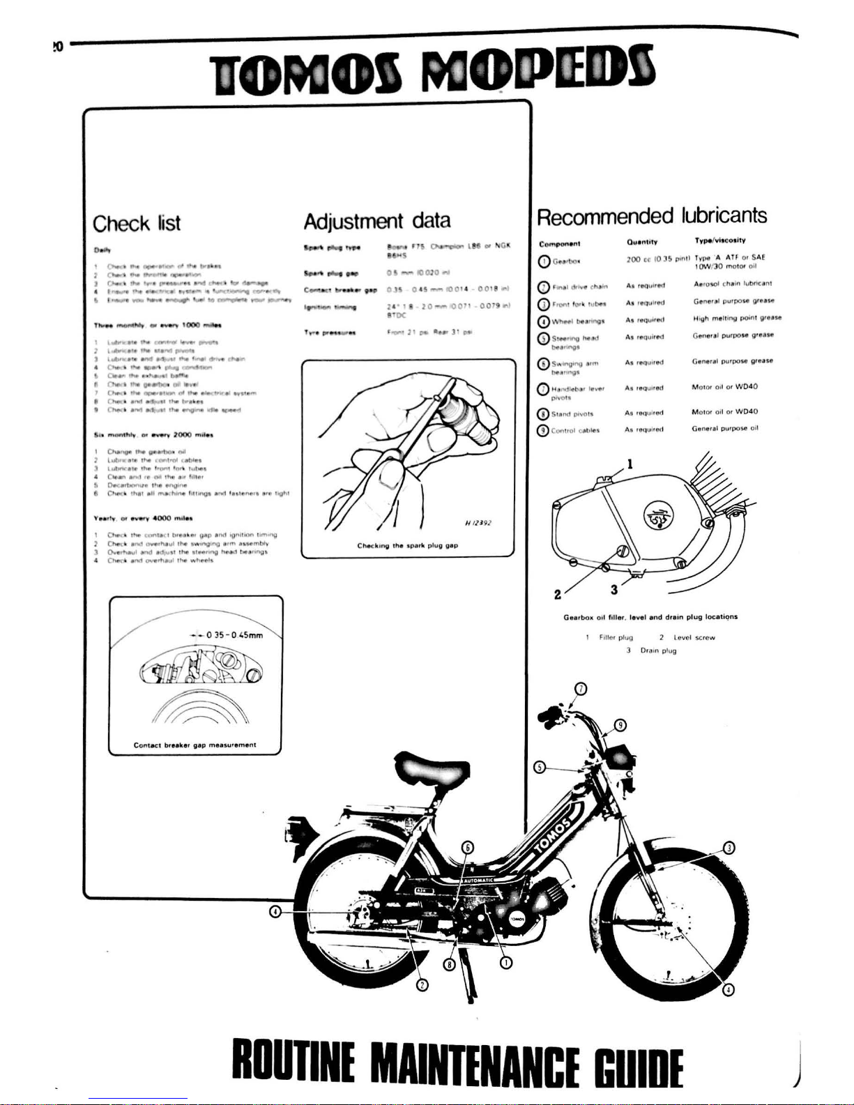
Check
list
l
....,_l...,~
.........
.
._........-
...
.._
,.
__
l...,.
•.
.,
,~
.......
l.,Vft
... ,
,...,
......
.,.
~
, ........... .,.,....,
..
.....
....
tNlf'I
4 , ....., ,
...,.
... ~ ...
~.,..,..
c
...
,.
,..,...
,_..,
"'-'.
·~
w-..
_.
,,,..,
'
.._.,...
......
...
J (
.....
~
r'Wt
•• , .....
f'IA
,._
• 1>tC e
"1
'
c
Not
.
•N'I
r1 " '""'
....
. . ,
(
Not
•
•<wt
._'1
.,
,.._
.........
II/
..,
..
.,,.....
~
..
the
...
'"' • ""
l
wt;
W
•tri
ft~
I
tlif\t't
• I
•IMil
\ut"'1(attt"""
1
,,,..1
, ,
tu~-t
C-
111.,..
.,,
1
ft
tM
th4t
•"
f1IH
11
Ott<•~_,,.._.~
..
CNw
lt
th•I 1tW
mt'
•
hll\tl
l
•tttngl
a
""1
lultt
n*ll •'"
h(lt\I
0.... •
IN
,,_,
,. , I l>rt"•lt.11t
Q"P
a
nd
topl~~t.ort l1t'1•~
()wi.<:• r'W1
~·~"'4
,.,,.
IWl~·no
••
rn
H.H
tnbt\'
0.,,.-,"""
I
•""°
.c.i
l'U
• I thfll tlH
f"'Q h11ta
;1 hee11ng•
It
~
°'""
..
mev1
ttw
-.
h.t>
i"la
--035-045mm
Adjustment
data
_,.
__
-_.l
., i.G
g
t.
-
()
QJO""'
2'
1110-t<>on
OO
! r
1
1·oc
'
!'0""!'!
11C*
tt
...
l ' •
C
h.ckmv
tha
tper
k
pl
ug
gap
Recommended
lubricants
Compon~
t
Ouentit'
r,
pelvi•
co1
lty
0 Gu
,bo
•
200
ct
10
Jb
po
n1l
Tvpe A A
lf
or SAE
IOW
IJO molar
oU
0 ,
""''
di
-v
• t
hl
lf'I
A
.J
rtt(luU"'
Aaro'-0' ch1
1n lut>ncent
(D
rrori
1
'°'
'
h.ibe~
AJ •
•au!rtd
Gennr1I
purpoH
oreate
0 \.\-'hftl
be1
nng
1
At teQ
v••MI
U'Qh
mtll
ll'
'O
J>Ot'll greue
<D
St"""V
h.,.
d
AJ
lttQUlted
Ge
ner
t l
purpe>se
grease
be•"''9•
@ s"'
""'tio0
•"''
AJ
1.au
ued
Gentr•I
purpoH
grnH
~"''''tV
·
(!)
H•r~tl
eb•
t
lttver
As
1euuued
M
OIC
)f 011
or
W04
0
()1¥01•
@ S
ttt
ndDt'IO
IS
A
.!
1ec1u11ed
Mo lor Otl
Of
W04
0
©
Cc>f'
t10I C
f't
>I• •
At roc1ul10'1
G1rne1al
pu1
pc>se 011
Gearbo•
011
filler, level
and
drem
plug locetiqns
Filler plug
Level screw
Oram
plug
RDUTINI
MAINTINANCE
GUIDI
j
Page 22
Routine
maintenance
Periodic routine maintenance is a continuous process which
should commence
immediately
the machine is used. The object is to
maintain all adjustments and
to
diagnose and
rectify
minor
defects
before
they
develop
into
more
extensive. and
oflen
more expensive.
problems.
It
follows
that
if
the
machine is maintained properly,
it
will
both
run and perform
with
optimum
efficiency.
and
be less prone to
unexpected breakdowns. Regular inspection
of
the
machine
will
show
up any parts
which
are wearing. and
with a little
experience.
it
is
possible to obtain
the
maximum
life
from
any
one component,
renewing
it
when
it
becomes
so
worn
that
it
is liable to fail.
Regular cleaning can be considered as
important
as
mechanical
maintenance. This
will
ensure
that
all
the
cycle parts are inspected
regularly and are kept free
from
accumulations
of
road
dirt
and grime.
Cleaning is especially
important
during
the
winter
months
. despite
its appearance
of
being a thankless task
which
very soon seems
pointless. On the contrary,
it
is during these
months
that the
paintwork,
chromium
plating, and
the
alloy casings suffer the ravages
of abrasive
grit
. rain and road salt. A couple
of
hours spent
weekly
on
cleaning the machine
will
maintain its appearance and value, and
highlight small points. like chipped paint, before
they
become a serious
problem.
The various maintenance tasks are descr
ib
ed under
the
ir respective mileage and calendar headings. and are accompanied by diagrams
and
photographs where pertinent.
It should be noted
that
the
intervals
between
each maintenance
task serve only
as
a guide.
As
the
machine
gets
older. or
if
it is used
under particularly arduous conditions,
it
is advisable
to
reduce the
period
between
each check.
For ease
of
reference
most
service operations are described
in
detail under
the
relevant
heading. However, if
further
~eneral
inf_or-
mation is required,
this
can be found under
the
pertinent Section
heading and Chapter
in
the
main
text. . •
Although
no
special tools are required
for
rout1~e
mamtena~ce
,
a
good selection
of
general
workshop
tools
is
esse~t1al:
Included
in
the
tools
must
be a range
of
metric
ring
or
combination
spanners, a
selection
of
crosshead screwdrivers, and
two
pairs
of
circlip pliers, one
external opening and the
other
internal opening.
Additiona
lly.
owing
to
the extreme tightness
of
most
casing screws on Japanese machines,
an
impact screwdriver, together
with
a choice
of
large
or
small cross-
head screw bits, is absolutely indispensable. This
is
particularly so
if
the engine has
not
been dismantled since leaving the factory.
_,,..--'
Cleaning
the
machine
Keeping
the
motor
cycle clean should be considered as an
important part
of the routine maintenance,
to
be
carried
out
whenever
the need arises. A machine cleaned regularly
will
not
only
succumb
l
~!iS
speedily
to
the
inevitable corrosion
of
external surfaces. and hence
maintain
its mark
et value,
but
will
be far more approachable when the
time comes
for
maintenance
or
service
work
. Furthermore. loo
se
or
failing components are more readily spotted
when
not
partially
obscured
by
a mantle
of
road grime and oil.
Surface
dirt
should be removed using a sponge and warm, soapy
water
; the
latter
being applied copiously
to
remove the particles of
grit
which
might
otherwise
cause damage
to
the
paintwork
and polished
surfaces.
Oil and grease
is
removed
most
easily
by
the
application
of
a
cleaning solvent such as 'Gunk'
or
'Jizer
".
The solvent should be
applied when
the
parts are still
dry
and worked
in
with
a sti
ff
brush.
Large
quantities
of
water
should be used when rinsing
off
, taking care
that
water
does
not
enter
the carburettors.
air
cleaners or electrics.
If
desired a polish such
as
Solvol Autosol can be applied
to
the
aluminium alloy parts to restore
the
original lustre. This does not apply
in
instances.
much
favoured
by
Japanese manufacturers. where the
components are lacquered. Application
of
a wax polish
to
the cycle
parts and a
good
chrome cleaner
to
the
chrome parts
will
also give a
good finish .
Always
wipe
the machine
down
if
used in the w et. and
~ake
sure the chain is
well
oiled. There is less chance
of
water
getting
m~o
control cables
if
they
are regularly lubricated .
which
will
prevent
stiffness
of
action
.
Page 23
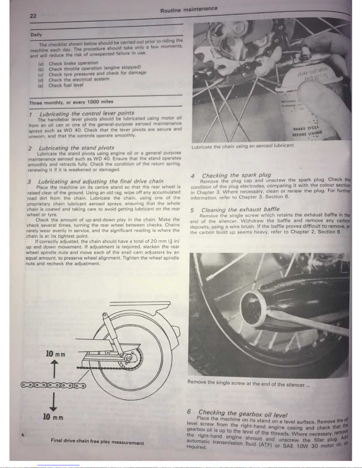
Rout1nemall1181181IC9
n.
cheddisC
lhowr1
below
should
be
carried
out
poor
to
rid
ng
the
m8Chine
NCh
day
The
procedure
should
take
only
a
few
moments
end
wiU
reduce
the
risk
at
~ed
fa
re
fn
use
(aJ
Check
brake operauon
bJ
Check throttle operation eng e
stopped
(cl Chee\
tyre
pressures and ch for
damage
d Check the e ectrlcal
1JY51em
(el
Check
f11
fevel
ThrM
monthly,
or
every
1000
miles
1
lubricating
the
control
lever
points
The handlebar lever
plvot
should be lubricated
us
ng
motor
oil
from an o I can or one
of
the g nerel-purposc aerosol
ma
ntenance
sprays
such
es
WO
40
Ch
c that the lever
pivots
are secure
and
unworn.
and
that
the
control operate
moothly
2
lubricating
the
stand
pivots
Lubncat tho stand pivots using engine
oil
or
a general purpose
melntenanc aerosol such as
WO
40
Ensure that the stand operates
smoothly
and
retracts fully Check the condition
of
the return spring
r newing
11
if
11
11
weakened
or
damaged
3
lubricating
and
adjusting the final drive chain
Place the machine on
its
centre stand so
that
the rear wheel
is
raised clear
of
the ground. Using
an
old rag.
wipe
off
any accumulated
road
dirt
from
the chain Lubricate tho chain, using one
of
the
proprietary chain lubricant aerosol sprays. ensuring that the whole
chain is coated and taking care
10 avoid getting lubricant on the rear
wheel or tyre.
Check
the
amount
of up·and
down
play in
the
chain. Make the
check several times, turning the rear wheel between checks Chains
rarely
wear
evenly in service , and the significant reading is where the
chain is at
its
tightest point.
If
correctly adjusted, the chain should have a
total
of
20
mm
(f in)
up and
down
movement.
If
adjustment is required. slacken the rear
wheel spindle nuts and move each
of
the snail cam adjusters by an
equal amount,
to
preserve wheel alignment. Tighten the wheel spindle
nuts and recheck the adjustment.
IO
mm
T /
~
l
10
mm
Final
drive
chain free
play
measurement
Lubricate
the
chain using an aerosol
lubricant
4 Checking
the
spark
plug
Remove
the
plug
cap
and
unscrew
the spark
plug. Check t
condition
of
tho
plug
electrodes.
compari
ng
it
with
the
colour
sectl
in Chupter
3.
Where
necessary, clean or
renew
the
plug.
For furth
information, refer
to
Chapter 3 Section
6.
5 Cleaning
the
exhaust
baff
le
Remove
the
single
screw
which
retai
ns
the
exhaust
baffle
in
end
of
the
silencer. Withdraw
the
baffle
and
remove
any
ca
deposits, using a
wire
brush
If
the
baffle
proves
difficult
to
remove,
the carbon
build
up
seems
heavy,
refer
to
Chapter
2,
Section
8.
R
emo
ve the
single
screw
at
the
end
of
th
·1
e
s1
encer
...
6
Checking
the
gearbox
oil
level
Place
the
machine 0 't
level
screw
from
the
.
~1 ~stand
on a level
surface.
Re
gearbox
oil
is
up
to
ther;g
tj
and
engine
casing
and
chtCk
the
right-hand
engin
ev~
of
the
threads.
Where
nece
automatic
transmissio~
~
~~ud(
and
unscrew
the
tiller
required.
ui
ATF)
or
SAE
10W
30
Page 24
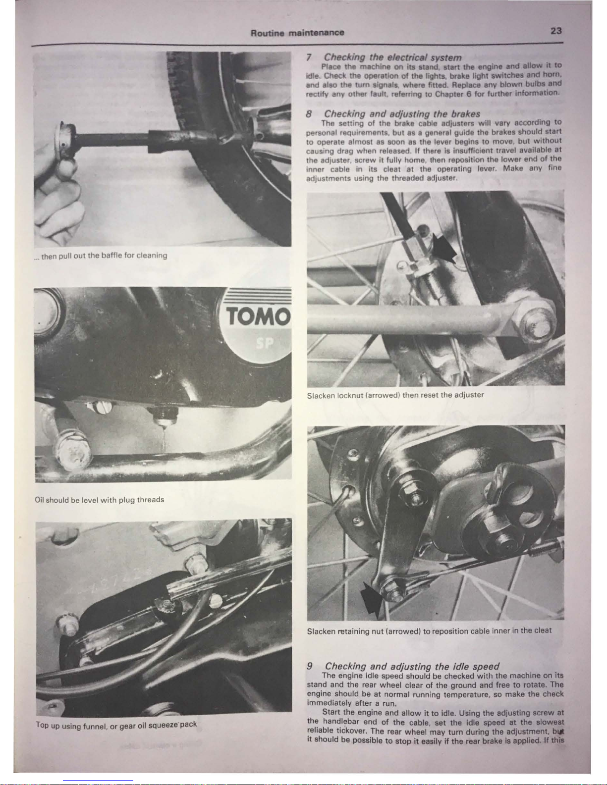
• then pull
out
the baffle
for
cleaning
Oil
should be level
with
plug threads
Top up using funnel.
or
gear oil squeeze pack
•
7 Ch«lcing
the
eltlctricel
system
Pl•ce
the
m11chlne
on
Its
stand.
atwt
the
engine
end
dow
•
ID
idle
Outck
the
oper•tlon
of
the
lights. breke
light
awltchee
end
ham.
eod elso the
tum
slgnels where fitted Replece
any
blown
bu._
end
rectify anv
other
feult. referring to Chepter 8 for further
lnformedan
8 Checl<ing
snd
adjusting the brakes
The setting
of
the brake ceble edju1ters
will
very according
to
personal requirements ,
but
as e general guide
the
brakas ahould
start
to
operate almost
as
soon
as
the lever begins
to
move, but
without
causing drag
when
released
If
there
11
Insufficient travel aveilable et
the adjuster, screw
it
fully home, then reposition the
lower
end
of
the
inner cable in
its
cleat at the operating lever. Make any fine
adjustments using the threaded adjuster.
Slacken locknut (arrowed) then reset the adjuster
Slacken retaining
nut
(arrowed)
to
reposition cable inner in
the
cleat
9 Checking
and
adjusting the idle speed
The engine idle speed should be checked
with
the
machine
on
lta
stand and the rear wheel clear
of
the ground and free
to
rotate. The
engine should be
at
normal runn ing temperature, so make
the
check
immediately after a run.
Start
the
engine and
allow
it
to
Idle. Using
the
adjuatlng screw et
th~
han~lebar
end
of
the cable, set
the
Idle
speed
at
the
llowell
~ehable
t1ckover. The rear wheel may
tum
during
the
ed)ustrnent,
It
should be possible
to
stop
it
easily
If
the
rear brake
Is
applied. M
Page 25
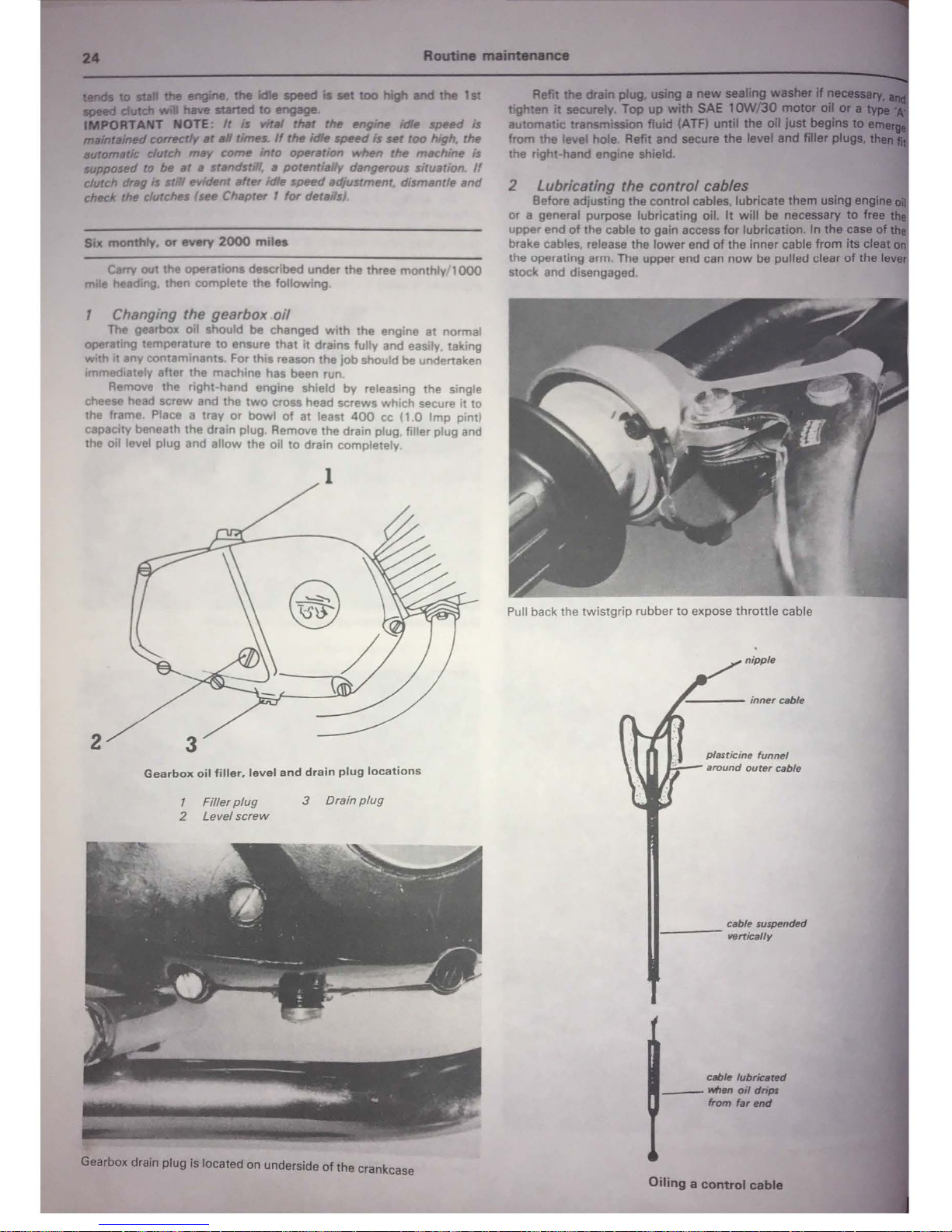
Routlne
.........
•11:e
....
tD
....
the
engine
the
Ille
speed
19
...
too
high
and
the 1
S1
......
dutch
wll
have 9taf'ted
IO
engege
IMPORTANT NOTE:
It
Is
wr.t
m.t
the
enfl""'
idle
~
Is
,,,.,,,alned
corrKt/r
.,
a#
ttmn.
If
the
Idle speed ls
set
too
high. the
MllOmatic clutch
may
come
mto
~11tton
when
the
machine ls
wpposed
to
be
at
a standst
'/,
• potentially dangerous
slru11t1on
If
clutch drag s
stfll
evi<Mnt
llfter
Idle
sf)ttd
adjustment. dismantle
and
check
the
dutches (see
Chapter
1
for
det1111&}
Six
monthly.
or
every
2000
mrlu
Carry out the operations descnbed under the three monthly
1000
m e head ng then complete the following
Changing the gearbox
oil
The gearbox oil should
be
changed
with
the eng ne
at
normal
operat
ng
temperature
to
ensure that
it
drains fully and eas ly, taking
with
t any contamln:ints. For this reason the
job
should be undertaken
1mmed1atcly after
tho
machine has been run
Remove
the
right hand engine shield
by
releasing the single
cheese head
screw
and the
two
cross head screws which secure
it
to
the frame Place o tray
or
bowl
of
at least
400
cc (1.0
Imp
pintl
capacity beneath the drain
plug
Remove the drain plug filler plug and
the oil level plug and
allow
the
oil
to
drain completely.
2
Gearbox
oil
filler.
level
and
drain
plug
locations
1
Filler
plug
3
Drain
plug
2
Level
screw
Gearbox drain
plug
is located on underside
of
the crankcase
Refit the
chin
plug. Ullng a
new
l88llng
...._If
tighten
it
securaty. Top
up
with
SAE
1C:JN/30
mo&arol
automatic transmission fluid
CA
TFJ
untU
the
oll
just
begJn9'
from
the
level hole. Refit and secure
the
level
end
fller
the right-hand engine shield.
2 Lubricating the control cables
Before adjusting the control cables. lubricate
them
using
or
a general purpose lubricating oil.
It
will
be
necessary
to
free
upper end
of
the cable
to
gain access
for
lubrication. In the case
of
brake cables. release the
lower
end
of
the
inner
cable
from
Its
cleat
the operating arm. The upper end can
now
be
pulled clear
of
the
I
stock and disengaged
Pull back the
twistgrip
rubber
to
expose
throttle
cable
cable suspended
•----
vertically
cablfl
lubriur.d
-
""".,,
oil
dripl
from
far
Md
Oiling a
control
cable
Page 26
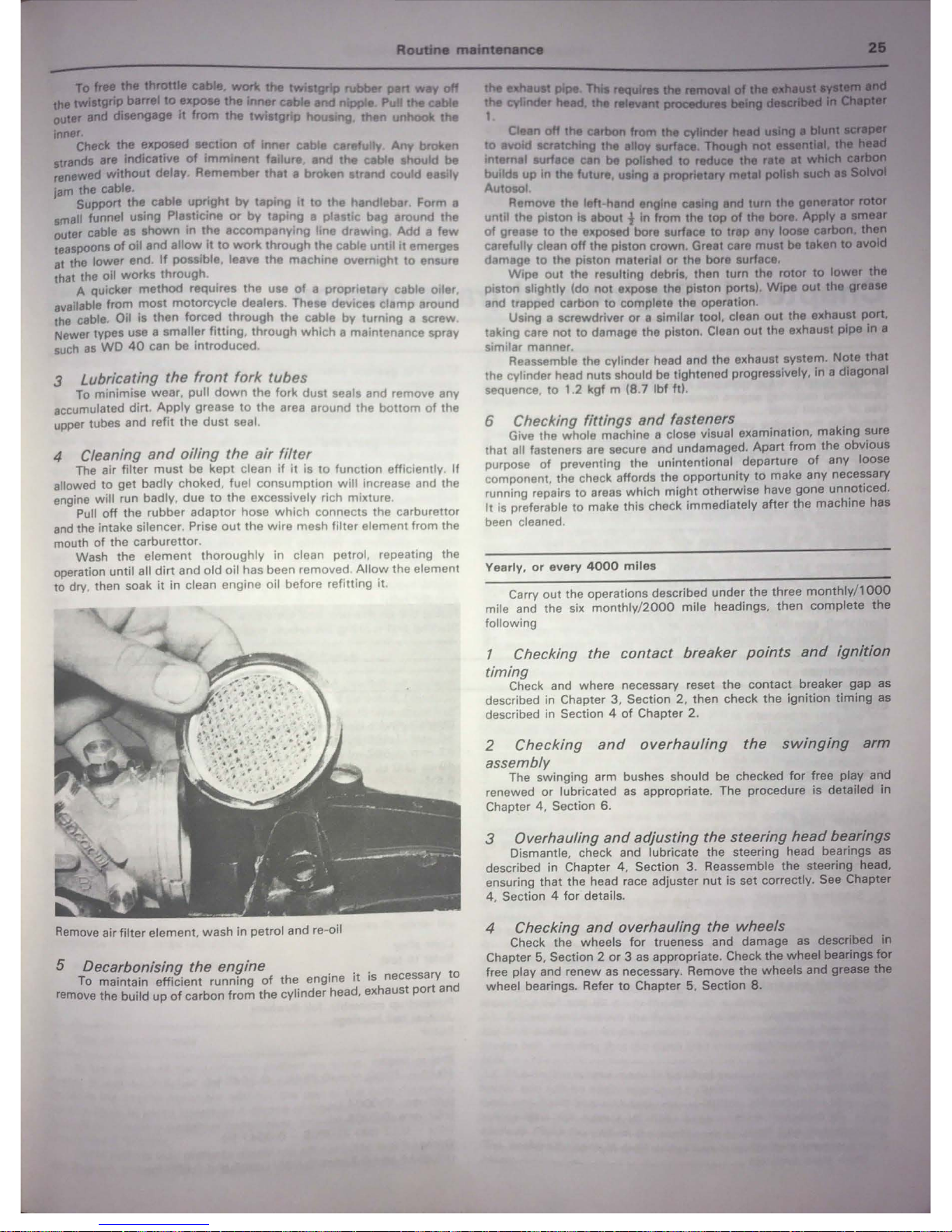
To
free thtl throttle
cmle.
wort
the
twiatgrip
rubber
pen
way
on
the (Wlatgrlp barrel
to
8xpoM
the
inner
cable
end
nipple
Pu the cable
outer
1111(1
diMngage h from
the
twistgrip
hou
ng then unhook the
1nner
Cheek
the exposed section
of
Inner cable carefu
ly
Any
broken
.irande are Indicative
of
Imminent
fa lure and
the
cable ahou d be
renewed
without
delay Remember
that
a broken atrand cou d easi
ly
jam the cable.
Support the cable
upright
by
taping
It
to
the handlebar Form a
small funnel using Plasticine
or
by
tap
ng o plastic bag orou
nd the
outer cable as ahown In
the
accompanying
lino
draw
ing
Add a
few
teaspoons
of
oil
and
allow
It
to
work
through
the cable
until
It
emerg s
at
the lower end
If
possible. leave tho machine overnight to ensure
that the oil
works
through.
A quicker method requ ires the use
of
o proprietorv cable oiler.
available from
most
motorcy
cle dealers. These deVtce cla
mp
around
the cable. Oil is then forced through
th
e cable by turning a screw.
Newer types use a smaller
fitting
. through wh
ich
a maintenance spray
such
as
WO
40
can be introduced
3 Lubricating the
front
fork
tubes
To minimise wea r pull
dow
n the fork dust seals and remove any
accumulated dirt. Apply
gr
ease to
the area
around the
bottom
of
the
upper tubes and re
fit
the dust seal.
4 Cleaning
and
oiling
the
air
filter
The air filter
must
be kept clean
if
it
is
to
function efficiently.
If
allowed
to
get
badly choked, fuel consumption
will
increase
<1nd
the
engine will run badly, due to t
he
excessively rich mixture.
Pull
off
the rubber adaptor hose
which
connects the carburettor
and
the intake silencer. Prise
out the
wire
mesh filter element from the
mouth of the carbure
ttor
.
Wash the e
lement thoroughly in clean petrol. repeating the
operation until all
dirt
and old oil has been removed A
llow
the element
to dry, then soak
it
in clean engine oil before refitting
it
Remove
air filter element, wash
in
petrol and re-oil
5 Decarbonising the engine . . . t
To maintain efficient running
of
the
engine
1t
1s
necessary
0
remove the build
up
of
carbon
from
the cylinder head. exhaust port and
O.en
off
the carbon
from
the
cyllnder held
Ullnl
•
to
~d
sc:ratchlng
the
elloy
turfece
Though not
1111111111.
Internal aurfece can
be
polished
to
reduce
the
rwte
at
which
builds
up
In
the
future, using a proprietary
metal
polleh
auah
• 8otilf
Autosol
Remove the left-hand engine casing end
tum
the generator ratOr
unti
l the piston Is about t In from the
top
of
the
bore Apply •
llMlf
of
grease
to
the
exposed bore surface
to
trap any
loote
cerbon
then
carefully clean
off
the piston crown . Gre1t care must
be
taken
to
avoid
d mago
to
the piston material or the bore surface.
Wipe
out
the resulting debris, than turn the rotor
to
lower
the
piston slightly (do
not
expose the piston ports)
Wipe out
the
gre1H
and trapped carbon
to
complete the operation.
Usi
ng
a screwdriver
or
a similar tool, clean
out
the exhaust port,
taking care not
to
damage the piston. Clean
out
the exhaust pipe
In
a
similar manner.
Reassemble the cylinder head and the exhaust system. Note
that
the cylinder head nuts should be tightened progressively,
in
a diagonal
sequence to 1.2 kgf m (8.7
lbf
ft).
6 Checking fittings
and
fasteners . . .
Give the whole machine a close visual examination, making sure
that all fast
en
ers are secure and undamaged. Apart from
the
obvious
purpose of
pr
eventing the unintentional departure
of
any
loose
component. the check affords the opportunity
to
make any necel'.5ary
running repairs
to
areas which
might
otherwise have gone
un~ot1ced.
It
is preferable to make this check immediately after the machine has
been cleaned.
Yearly.
or
every
4000
miles
Ca
rry out the operations described under
the
three
monthly/1000
mi
le
and the six monthly/
2000
mile headings, then complete the
following
1 Checking the
contact
breaker
points
and
ignition
timing
Ch
eck and where necessary reset
the
contact breaker gap as
described in Chapter 3, Section 2, then check
the
ignition
timing
as
de
sc
ribed in Section 4
of
Chapter 2.
2
Checking
and
overhauling
the
swinging
arm
assembly
The swinging arm bushes should be checked
for
free play and
renewed
or
lubricated as appropriate. The procedure is detailed
in
Chapter 4. Section 6.
3 Overhauling
and
adjusting the steering
head
bearings
Dismantle, check and lubricate the steering head bearings as
described in Chapter 4. Section 3. Reassemble the steering head.
ensuring
that
the head race adjuster
nut
is set correctly. See Chapter
4, Section 4
for
details.
4 Checking
and
overhauling the wheels
Check
the
wheels
for
trueness and damage as described In
Chapter 5, Section
2
or
3 as appropriate. Check the wheel bearings for
free play and renew as necessary. Remove the wheels and grease
the
wheel bearings. Refer
to
Chapter 5, Section
8.
Page 27

Chapter 1
Engine and transmission
Content.
General dellCfipti
on
. ... ...•.
...
.. • ...
. .
------··
Operations with t
he
engi
ne
unit
in t
he frame
····-·-·-·-·--·
Open11
ion1 requ
iri
ng engine removal
UICI
of
soeclal 1
0011
.•••.....••..•
R
emoving the
eng
ine unlt f
rom
the
frame
D
asm11ntltng the
engine/
gearbo• unit . preliminaries
..
Dism&ntltng t
he
engine/
geerbo•
unit removin
g t
he
cylinder head
b11n
el
and
pis
ton
. . ................................... .
D
i5man
tli
ng the
engine/ge11
rbox uni
t. remov
ing
the flywheel
gen
ra
tor assembly
.. ..
........................... .......
..
D1sman
tltng t
he englne/
gearbo)( unit·
remov
ing
the transmission
co
mpo
nents ........................................................................................ .
D
ismantling
the
engine/gearbox unit : separati
ng
the crankcase
1
2
3
4
5
6
7
8
9
halves ...................... ................
....
....................................................
...
....... 1 O
E.umination 11
nd
renovation: general .................................................. 1 1
Cylinder head· uamlnation and renovation ....................................... 12
Cylinder barrel: examination and renovation ...................................... 13
Piston and rings
: exa
minat
ion and renovation ..................................
14
Cranks
haft
asse
mbly
: exa
minat
ion and renovation .......................... 15
Sm
all-e
nd
bus
h: examination· and renovation ................................... 16
Specifications
Engine
Typ
e .....................................
.......................................
............
....
...
...
.........
.. .
Bor
e ..........................
...
............................
...
..............
.................................
..
.
Stroke
............................................................................
.......
.................
......
.
Dis
placement
..........................................................
................................
...
.
Compression ratio ..........
....
....................................................................... .
Power
output
.........................................................................................
....
.
Cylinder head
Type .....................................................
...
.....................................................
.
Cylinder barrel
Type .......................................................................................
....
.................
. .
Standard diameter ...........
..
....................................................................... .
Piston
Type
·················································
·····
···
·······················
···
···············
·······
···
··
Diameter
....
...........................................................................
.......
.............
..
.
Crankshaft assembly
~~~
·b·~·~·
;1~~~
··:.·.·.·::
.·
.·:
.
·.·:.
·:::
:
.·.·.·
.
·::::.·
.
·:::.
·
:.·.·.·::.·.·::.·.·:::.·.·:.·.·.·.·::.·.-.·.
·
.·::
.-.
·
.·.·.·.·.·.
·
:.·.·.·
.
·:.·.·
.·.
·.·:.·.·.
·
.·:.·:.·.·.-.
~~~~ln:n~e~:~~~~
·:···
·
················
·
············
·
·············
·
········
·
··
··
···········
· ·
······
·
·····
6~~~~~
·
~;
·::::::::::::::
:
::::
:::::::
:
:::
:
:::::::::::::::::::··········
·
·············
·
········
·
········
·
·
Maximum
crankshaft runout: .................
....
...................... .
At
main
bearing journal ...................................
....
............................ .
At
mainshaft ends
·············································
·············
·············
···
···
·
Crankshaft end float
.................................................................................
.
Adjustment
method
......................
....
...... .
Shim
sizes available ······
············································
......
...
...
...............
...
......
...
.........................................
..
Main and gearbox bearings and
oll
seals: examinat
ion
and
re
novation ..
.......................................................
.......
.........
...
...................... 17
Crankca
se
castings: exemlnatlon
and
renovation .........................
....
18
Centrifugal c
lut
ch asse
mbly: dismantling
. overhaul
and
reesse
mbly
.......................
.......................................................................... 19
Tran
smissio
n gears and roll
er clut
ch:
dismantling. ove
rhaul and
reassembly
..
.................................
....
..........................................................
20
Klckstart mechanism: examinat
ion
and
renovati
on
........................
..
21
Engine reasse
mbly
: general ........
..................................................
.......
..
22
Engine reasse
mbly
: refi
tting
the
main
bearings
and
oil
seals
and checki
ng
crankshaft end
float
....................................................... 23
Engine reasse
mbly: joining
the
crankcase
hal
ves ....................
........
. 24
Engine reassembly: re
fitt
ing the transmission shafts and
centrifugal c
lut
ches ....................
...
...........................................................
25
Engine reasse
mbly
: r
efitti
ng the
flywh
eel
generator
asse
mbly
......
26
Engine reasse
mbly: refitting the
pis
ton. cylinder
barrel and
cylind er head ............................
..
............................................................... 27
Fill
ing
the engine
unit
into
the
frame
....
.............................................
28
Starti
ng
and running the
rebuilt
engine
..............................................
29
Single cylinder air-cooled
two-stroke
38
mm ( 1.
496
in)
43
mm
( 1.
692
in)
49
cc (3.0 cu in)
8.5:1
2
hp
~
5500
rpm
Light
alloy
Cast iron
38
.01 -38.
02
mm
(1.4964 -1.4968
in)
Light
alloy
Refer
to
text
Pressed-up
assembly, full flyw
heel
Journal ball
beari
ngs
Roller
Bronze
bush
10
.01 -10.
02
mm
(0.3941
- 0.
3945
in)
0.01
mm
(0.0004
in)
0.
02
mm
(0.0008
in)
0.
02 -0.12
mm
(0.
0008
- 0.
004
7
in)
shims
0.1, 0.
15
and
0.2
mm
(0.004
. 0 .
006
and
0.
008
in)
Page 28

Chapter 1 Engine
end
tr•namlHlon
27
Prlm•rv
tr1n1ml11lon
Typo
Aot
o ·
111t
......
2nd
St
nr
tor oorir
Clutch ond float
Thrust wosh ra ov
II
bl
Shoo to drurn cl arnncn
secondary
tran1ml11ion
Typo
........
............................................
....
....................
Choln
si
ze .
·········
..............................
······························
Torque
wrench
aetting1
component•
..........
...
..........................
...
.......................
............................
...
.........
...
.................
...
..
Clutch rotalnlng
nut
Tronsrnl slon covor screw
Cylinder hood nut ......
Generotor rotor n
ut
.........................
.....
......................
...
...
Qener•I
de1criptlon
The
Tornos
mopod
s e
mpl
oy
o single cylinder air-
coo
led
two~stroke
engine built In
u
~it
with
th
outomotlc tw
o-speod transmission . The
engine
Is
of
tho piston ported
typ
o. u I
ng
a cast Iron cylinder barr
el
in
conjunction
with a light
olloy
cyli
nder
hood, tho folnt between the two
effected
by
ground soollng locos.
The crankshaft is o
pr
osso
rl
up
nsso
mbly aupportcd
on a fournal
ball
main booring at ooch o
nd
. A rollor
big
end is
fltt
od.
whilst
tho small
end bearing
Is
of the bron10 bush
typ
o.
A
two
-speed
primory
tronsrnlssion
system is
fitted
and
Is
controlled
by two centrlfugol clutches. Those operate sequentially 10
ensure that the machine
moves
otf s
moo
thly
as the
throttle
is opened.
As
the mac
hine gath
ers spood tho second, higher ratio. overrides 1st
gear
to
give better
economy. On
steep gradients
the
machine
will
revert
to
1st ge ar as the engine speed falls.
2
Operations
with
the
engine
unit
in
the
frame
The
items
listed
bel
ow
can
be remov
ed and overhauled
without
removing the engine un
it
from the
frame. It
should be
noted, however
,
that engine removal is a rela
tiv
ely easy task and should take about half
an
hour
or
less. In view
of
this
it
is recommended
that
where
a number
of operations are
to
be
undertaken. th
e engine should be removed
to
gain better access and
more
com
fortable working conditions
.
a)
Cylinder head. barrel and
piston
b)
Centrifugal c
lut
ches and transmission gears
c)
Kickstart mechanism
d)
Flywheel genera
tor
assembly
3
Operations
requiring
engine
removal
To gain access
to
the
following
components
It
will
be necessary
to
r~move
the engine
from
the
fram
e,
remove
the
flywheel generator.
k1ckstart
mechanism and
the
transmission
components
to
allow
the
crankcase halves
to
be separated.
a)
Crankshaft assembly
bl
Main
bearings
c) Transmission bearings
4 Uae
of
special
tools
In the course
of
the
workshop
project
on
which
this
manual Is
based
it
was established
that
it
is possible
to
strip and reassemble
most
of
the engine assembly
without
the
use
of
the
manufacturer's
service tools.
In
some instances a degree
of
Ingenuity
will
be required
to
hold
or
remove a
particular component
, and details
will
be
found
In
the relevant Sec
tion
.
Some
own
ers may
prefer
to
obtain
the
official
tools
, and these
c~n
be
ordered through
Tomos
dealers.
Whilst
the
tools are primarily
A
11tom1tlc
1....,
0 llOfl!ld
Oetl
r drlvo
tw
n Cflntr
lfug I ChJtch
I
4 3 3 I I 1 / x
74
TJ
2 4
02
t (20 JI 4
11
0 4
65
t {"
...
71 tJ
0 1 3 0
mm
10004 0012
lnJ
0 3 and 0 6
mm
1
0012
1nd O
020
lr1J
0 4
mm
(0
0167
lnl
approc
Ch1ln
i
11
4 In,
90
llnlla
kgf
m
2.5
t.O
1.2
J.O
lbf
ft
18
.0
7.2
8.7
21
.7
Intended for professional use. many can
be
used
to
advantage
at
homn.
6
Removing
the
engine
unit
from
the
frame
Pl
ace the machine securely
on
Its
centre
stand
leaving
adequate
working space on
both
sides. Place a
bowl
or
drain
tray
beneath
the
transmission drain plug.
which can
then
be
removed and
the
oil
allowed to drain. Note
that
the transmlSBion casing
holds
about
200
cc
11
Imp
pint). Leave the oil
to
drain
whilst
continuing
the
dismantling
sequence. remembering to refit
the
drain
plug
before
the
engine
is
lift
ed
out
of the frame
to
avoid
spilling
any residual oil.
2
Wh
ile the oil Is draining, remove
the
two
side
covers
. Each
is
retained
to
the frame
by
two
self-tapping
screws
on
the
upper
edge
and a single larg e cheese-headed
screw
at
the
side. Remove
the
single
bo
lt
whi
ch secures each footrest and
lift
them
away
.
J Slacken
the
nut
which
retains
the
kickstart
lever
cotter
pin. leaving
the nut flush
with
the
end
of
the
thread.
Using a soft
faced
mallet
or
a hardwood block and a
hammer, drive
the
cotter
pin
out.
Remove
the
nut and displace the
pin
to
free
the
kickstart
lever. Lift
away
the
spacer
followed
by
the
kicks
tart
return spring and
its
two
end
caps
.
4
Slacken and remove
the
three
screws
which
retain
the
engine
left-
hand cover, then
lift
it
away. Note
that
if
It
Is
intended
to
separate
the
crankcase halves
It
is advantageous
to
slacken
the
gearbox
sprocket
nut
at
this
stage. Straighten
the
locking
tab,
then hold
the
sprocket
by
applying the rear brake whi
lst
the
nut
is
slackened
by
one
or
two
turns
.
5 Turn
the
rear wheel
until
the
final
drive
chain
joining
link
is
a~cessible.
Using pliers, displace
end
remove
the
spring
clip,
disengage
the
ends
of
the
chain and
remove
it.
6
Slacken
the
two
screws
which
retain
the
cable channel
to
the
underside
of
the
tank. The
channel
has
keyhole-shaped
slots
and can
be
slid
to
one side and
lifted
clear.
7 Unscrew
the
knurled
carburettor
top
and
pull
out
the
throttle
valve
assembly.
It
can
be
left
attached
to
the
throttle
cable and lodged clear
of
the
engine.
8 Disconnect
the
leads
from
the
flywheel
generator
at
the
Lucar
connec
tors. Note
that
the
engine
earth
lead
will
remain attached
but
will
be freed
when
the
engine
mounting
bolts
are removed .
9
Unscrew
the
union
bolt
which
retains
the
fuel pipe
to
the
carburettor. Disengage
the
pipe and
refit
the
bolt
and sealing washers
for
safe keeping.
1
0 Remove
the
two
exhaust pipe
nuts
and
the
single silencer
mounting
nut
and
lift
away
the
exhaust system.
11
Slacken and remove
the
three
engine
mounting
bolt
nuts,
holding
the
bolt
heads
to
prevent
rotation.
Displace and remove all
but
the
centre bolt, ensuring
that
the
earth lead
terminal
is freed
from
the
front
bolt
.
12
The engine is
now
ready
to
be
lifted
away
from
the
frame. It
is
not
h~avy
and
will
be
easily managed
by
one
person.
Support
the
engine
wit~
one hand and
withdraw
the
remaining
bolt. Lower
the
engine
,
notrng
that
the
rubber
air
filter
hose
will
pull
clear
of
the
intake
~i~en~er
.
Pla~e
the
unit
on
the
workbench
to
await
further
dismantling
.
e rntake silencer
will
drop
as
the
unit
Is
removed
and
may
be
lifted
away
.
Page 29

f teppmg screws
5
2b
and
by
a single cheese heeded scrow
at the side
5.6 Slacken retaining screws and disengage channel
5. 7
Un
screw carburettor
top
and
withdraw
the
throttle
valve
assembly
5.8 Disconnect the generator wiring at the Lucar connectors
Page 30

,,,,,,--
-
Chapter
1
Engine
end
tr•nsmlalon
29
I
Ofernentllng
the
englne
/ g11tbo11
unit
·
~•llmlneri"
8
.,
10
11
,
11riy
(11smnntl ng
wo1k Is undet111ken. the
ex_tetn11
1 aurfRces
the!
unit ah
ould
bt1 thoroughly
clun11d
11nd
degt
11ted Th 1 will
of
11111
the co111nmlr111tlo11
of
the
onglnt lnt
em1111, 11nd will
111ao
meke
~=r•dng
8
lot
081101 8nd cl
Hne
1 A hi
gh flu h
p0l
nt
solvent. 1uch
111
81
"
11
1
11
(ke•o•on
el
cen be u
1ed
, 01
better
11111. e proprie
tary engine
P eosor
11uch
H Gunk.
U111
old
palntbtvehea 11nd too
thb1v1he1
to
:0:,~
tho solvent Into tlH1
v11rlou1
19ce1111 of the engine
c1t11ing1
. Teke
lo
.,.-elude
11otven
t or
water
Ir- om tho t1fectr
ic11I co
mpanent
1 end
co
re!
u
11
,11,1 nnd ox_h8ltlt pans. The VIM!
of
petrol
lg111ofl
ne)
111
e chutnl
ng
,nl!fli
urf1
shou
ld
be
1tvo
lded
, beceuee
the
v11pour
11 ex_ploslve
end cen
mi t
ox
ic
11
usnd In
11 conflnnd
1p11
ce.
2
- Whlln
cle11
n end
dry, 11rr11nge the
unit
on
the
workb
enc
h, leavi
ng
a
auitnble cl
o11r
11r11e
for working.
Gethor e 111
loc1ion of s
mell cont
11lners
snd
p11111t
ic
begs
110
that
Pllt1!!
can
be
grouped together In en eeslly
ldo
ntlfleble
mann
er.
Some
popor
end 8 po
n should
be oo
hend
10
permit notes to be
modo end
lnbol
s e
ttached where nec
ess11ry
. A
supply of cl
on
n regs is el
10 required.
3
9
11
fore commencing wor
k. r
end
through the
1tppropri111e
section
so
th
et some
idi!•
of
the nece1"ary procedure cnn
be
goinod. Whon
remo Ing
the
v11rlou.1
engine
c:o
moonents
It should
be
notud
th
It
groot
force 1 seldom reoulred,
unleu
specl
f14td. In
mt1ny coses. o
co
mp0nent
s r luc
tan
ce 10 be
romoved
Is indicative
of
on lncorroct
1ooro11
ch or r
ooiovat method. II
In
11ny
doubt
, re-check wi
th th
o IU•I.
7
Dl1m1ntling
the
engln1
/geerboJ1
unit: r•movlng
th•
cylinder
hHd.
ban•I
end
pleton
1 This operation can
be
cnrrlod
out
with
the eng
lno
unit
In or
out
of
th
e fr
nme. II
the engine
11
Insta
lled
In the frame It will first
bo
nec
euary
to
remove
the
e111h11u11
1y11em
by
releasi ng
the two
e111
hnus1
part
flenge
nuts
and the 1lngle silencer
mounting nut
. In
olthor
caso,
release
th
e cnrbure
ttor
by
removing
the
two
flange
bolts and
lilt
It
cloor
of
the
b11rrel
.
2 Slncken evenly and progre111lvely
the
four
cylinder
head
nuts
,
turning
eoch ono
by
about t
turn
until
pre11ure has
been
reloasod from
th
e head. Run the
nuts
off.
then
lift
the
cylinder
head
away
from
tho
holding
studs
.
3
Th
e head will no
rm11lly
come
away
quite
easily.
but
If
corrosion
has occurred
between
It
and
the
holding
11uds.
spray
the
area
liberally
Fig. 1.1
Cylinder, pl1ton
and
crankcase
assembly
1 Crank.case halves
2
Left-hand
cover
3
Right-hand
cover
4
Stud
- 4
off
5 Crank.case gask.et
6 Cover gask.et
7
Dowel
pin
8
Oil
level
screw
9 Sealing washer
10
Oilfiller
plug
11
Sealing washer
12
Screw -17
off
13
Screw
14
Engine
mounting
bolt
15
Spring
washer
16
Washer
1
7 Cylinder
barrel
18
Cylinder
head
19
Cylinder base gask.et
20
Spark.
plug
21
Washer - 4
off
22
Nut
- 4
off
23
Piston
24
Piston
rings
25
Gudgeon
pin
26
Circlip - 2
off
27
Engine
mounting
nut
28
Wiring
grommet
29
Stud
- 2
off
Page 31

...
WD
4001 • .._
nwln
..
aence
woeol
If
nece.-y
lep
eround
N
....
ol
dw
hMd
whh e llOft
f8C8
meht
IO
etelst
In
MP818tlng
the
......
On
no
eocount
etternpt
IO
le¥9f
betwffn
the
heed
end
bafTel
r.c.:
dw
llght
~heed
Cffting
la
brint•
and H
frl
I red
4
Cl-*
lhet
the
l)itlton
la
11
the
top
of
the
bot•
If
necesurv
the
~
~n
be rotated
by
tumlng
the
generator rotor
Ult
the barrel
by
mout
an
lnd1
and
peel
eom•
d111n
rag
nto
th•
cram.ca
mouth
and around the
connect
ng rod
Th
1 precaut
on
wl I
pr
nt
any d brl1
from
entering the
cr1nlca
The barrel can
now
be I
It
d awav.
8U1JPOrt
ng
the
pi1ton
11
It
emerges
6
Ullng
rel p
pl
111
relea on
of t gudg
on
pin
clrcl
ps
The
pin
can now
be
removed
by
push ng
It
through from
th
oppos
t a de
If
the
pin
proves stubborn
warm
the
piston
by
wrapp
ng It n r g
eoaked n
very
hot
wat
r. Th 1 wl I ellpand
th
a loy and r I a
lta
grip
on the p n Place
the
gudgeon
pin
end
clrcl~
I d
th
p ton and
place
It
to
one
de
8 D
lamantling
the
engine/gearbox
unit: removing
the
flywheel
generator
auembly
N
ote:
If
th
centrifugal clutch Is
to
be
remov d
It
may
bD
necessary
to
have
the
g11nerator
rotor
in place as o
method
of
holdmg the
cr11nli.shaft
Refat
to
Section 9
for
details
Th flywheel g n rotor comPon
nts
mav
be
removed
with
th
cngln
in
or
out
of the frame
If
It hos
not
alreodv bnen
1emn11ed
It
will
be
nee ssary
to
drsmantl
th
klckstort m chanl m and romovo tho
left
hand outor covor. The procedure I
desc11bcd
In Section 5.
paragraphs 3 and 4.
2 Tha flywheel rotor
is
mounted
on
the tapered end
of
the
crankshaft. located
by
a small pin and retained
by
a single nut. When
romoving thn retaining nut
1t
will be necessary to prevent the rotor
from turning In tho absence
of
the correct holding tool (part number
732
2021 an alternative method
must
be
devised.
3
If
the cylinder head. barrel and piston
ha11e
been removed. the
crankshaft, and thus the rotor, can
be
immobilised
by
passing a
smooth round bar through the connecting rod small end
eve and
resting
the
ends on wooden blocks placed against the crankcase
mouth. The arrangement is shown in photograph
26.2c
. Another
Possible
method
is
to
use a strap wrench around the outer face
of
the
rotor.
4 Once the rotor
nut
has been removed. the rotor can
be
drawn
off
the tapered crankshaft end. The best method
by
far
is
to
use the
correct puller and this can be ordered through Tomos dealers
as
part
number
700.334.
Note
that
although there
is
sufficient clearance
to
use a legged puller, there
is
serious risk
of
damage
to
the rotor and
stator comPonents. For this reason the correct tool
must
be considered
essential.
5 Screw the puller
into
the
thread provided in the rotor boss. then
tighten the cen t
re
bolt
to
apply pressure
to
the crankshaft end.
Do
not
overtighten the centre bolt;
try
tapping the end sharply
to
jar
the
rotor
free.
If
necessary, tighten the centre
bolt
further then tap the end
again, until
it
comes free.
6
With
the rot
or
removed, attention can be turned
to
the stator.
Before this
is
removed note that
it
is advisable to mark the position
of
the stator in relation to the crankcase
by
scribing a line across
both
are~~·
This
~ill
allow
the ignition
timi
ng
to
be reset
to
its
original
p
os1t1on
during reassembl
y.
Slacken and remove the three retaining
screws and
lift
the st
ator
assem
bly
away.
9
Dismantling
the
engine/gearbox
unit: removing
the
trans
-
miuion
components
Final
drive
sprocket
.1
Not
e.
that this
operation is b
est
carried out
with
.
installed
'"
the frame because this
allows the s k
tb
he engine
f
h
d
. . proc
et
to e held
by
way
o t e nve chain and rear brake
whi
lst the s k · ·
Is
slackened (s.ee Section 5, paragraph 41. proc
et
reta ining
nut
2
If
the
engine has been removed and the
nut
h
slackened, a sprocket holding
tool
, Part Number
732
°lo~o
.
t
vet .been
from
the
manufacturer. In the absence
of
the
offici~I
·
~
available
drive chain around
the
sprocket and lock
it
b
too • loop
the
through
the
chain finks as
shown
in
photo~r~=~I~~
~dscrewdrlver
~et
In
position
, straighten the
tab
washer
and . . Hold
the
U81ng
I
30
mm
box
or
ring
spanner.
remove
the
nut
Centrtfupl
alutah
•••mbfy
3
If
the
engine
11
111N
In
the
frame drain
lhl
Remove
the
MVen
chffM
heeded
ICt9WI
which
,...,,.
die
outer cover and
lift
It
away
Note
that
the
tranarnlallon
have 1hlm wa1her1
which
m•v
11 k to
the
lmilda
of
the
are
to
reta n
theH
on
the r respect ve
lhah
anca
4 Flatten the
tab
wisher
to
allow
the
clutch
c.ntN
nut
removed
It
will be
necenary
to
prevent
the
clutch
from
turning•
nut
11
slackened using the holding
tool
732
202
referred
to
one
of
the methods deacrlbed
below
5
II
the cylinder head and barrel have been removed
PHI
•
round metal bar through the connecting rod 1m1ll end eye, au
Its onda
on
small wooden bloclur placed
on
the crankcate m
Alternatrv ly, use o
strap
wrench around the generator
rotor'•
o
foce
Wrth
tho clutch hold socurely, alacken and remove the
nut U1lng
a standard I ggod puller,
draw
tho clutch assembly
off
the
cr1nklha
h
end and ploc It
to
on
sldo.
Lift
off
tho clutch
thrull
washer and keep
h
with
thp clutch
Input
and
output
shafts
and
connecting chain
6
Th
Input and
output
shafts ere connoctecJ
by
an endless prim
chain and thus
must
bo removed as o pair. Once the centrifugal clu
assembly ha been
withdrawn
. the
two
shafts can be
lifted
out
of
casing and placed to one sldo. Remove tho thrust washer from the f
of
the Internal
output
shaft gear and place
it
over the end
of
the
ah
9.~
Remove
the
transmiss
ion s
hafts an
d di
se
ngage them
Prtmary chain
Page 32

-
ChaPter
1 Engine
•nd
transmission
31
W
Dismantling
the
engine/gearbox
unit: aeperetlng
c,..nkcase
halves
the
T""
It
should be
noted
that
the
crankcase
halves
can
be
after
the
engine unit
has
been
removed
and
th
see oar111·ed· only
· 1·
'
ed
pre 1mrn
ary
dismantltng
o~era
rons
~arrr
out
as
described
in
Sections
6
10
9
2
Using
~n
rmp~ct
dnver
, slac
ken
and
remove
the
cheese-head~
screws whrch
retain
the
crankcase
halves. It will
be
found
1
..
h
· f ·
r1
· h
fi
"
11
t e
main bearrngs are a at y
t1g t 11
over
the
crankshaft
end
d
consequently a
method
of
separating
the
casing halves
m~~t
a~
devised.
3
The
manufactur~r
_
produces
a special
tool
, Part
Number
736.88
8
•
for this
purpo~e
but
rt
1s
assumed
that
few
owners
will
have access
10
it.
The
following
method
was
adopted
during
the
workshop
pro
· t
and
works
well
provided
that
reasonable
care
is
taken
to
a'e~d
damage.
If
in
doubt
It
would
be
best
to
have
the
cases
s
eparat~o~Y
a Tomos dealer.
4 Arrange
the
assembl~
with
the
right-hand
side
uppermost
. usi
ng
wooden blocks
to
hold
1t
level.
Run
the
nut
onto
the
end
of
the
projecting crankshaft
end
to
protect
it.
Assemble
a large
two
-legged
puller over
the
crankshaft
end. hooking
the
legs
over
the projecting
crankcase
flanges. Place
slips
of
wood betwe
en
the pull
er
leg
s and the
crankcase
to
protect
the
latter
.
5 Tighten
the
puller
gradually
to
eKert pressure on
the
crankshaft
taking care
not
to
overtight
en it.
With
the
pull
er
load
ed as described'
tap the end
of
the
puller
bolt
to
Jar
the crankshaft out
of the bearing'
Repeat
this
sequence
unt
il
the
cas
ing
halv
es are separated. The same
method can be used
to
displa
ce
the crankshaft
from the left-hand
casing half (see
photograph)
.
6 The
internal
output
shah gear can
be
llft
ed
out
of tho loft-hand
casing half.
If
the
various bea
rings ar
e to be removed. they can be
driven out.
using a large socket. The bearing
boss area should first be
heated
to
e>1pand
the
alloy
using
a rag soaked
in
near boiling w ater.
The
use
of a blowlamp
or
an
oven
for
this
purpo
se is
not recommended
unless the
owner
has
eKperience
of
this
method
because of the risk of
distortion
if
the
heat
is
applied uneve
nly
or
in
e>1cess
.
10.5 Use a legged
puller
to
press
out
the
crankshaft
11
Examination
and
renovation:
general
1
d
·
it
for
wear
Before e>1amlning
the
parts
of
the
dismantle
engine
un
U •
it is essential
that
they
should
be
cleaned
thoroughly.
se
~
Petrol/paraffin miK
or a high
flash-point
solvent
to
ren:io~e
all
tr:~e~n~
old oil and sludge
which
may
have
accumulated
wrthm
the
~
·
Wh
.
al
fire
precautions
ere
petrol is
included
In
the
cleamng
agent
.
nor~
a
well-ventilated
should be taken and
cleaning
should
be
carried
out
n
place. . f
2 k
or
other
srgns o
Examine
the
crankcase
castings
for
crac
s
cialist
repair.
gamage.
~f
a crack is
discovered.
it
will
requlr~
at~~e
eKtent
of
wear
.
h
E~amrne
carefully each
part
to
determ~
Specifications
section
c
eck1ng
with
the
tolerance
figures
listed
In t e
of
th~
s
Chapter or in the main tut.
If
there Is any
doubt
about
the
~~tl
on
of a partl.c11lar companent.
play
safe and
renew
.
se a
clean. hot
free
rag.
for cleaning
and
drying
the vari
ous
components..
5 V ' I
. a
no
us nstruments for measuri
ng
weer are requi
red
, Inc
lud
ing
11
vem
ier gau
ge
or
external micrometer and a set
of
standard feeler
gauges. Also an l
ntemal
and an external micrometer
will
be required
to
:.'~ck
wear
limits. Add
itionally, although
not
absolutely necessary, a
•a
gauge and
mounting
bracket
11
Invaluable for accurate
me11sure
-
ment
of
end float. and pley between components
of
very l
ow
diameter
bores.
where
a micrometer cannot reach. After some
e>1per
lenco has
been
ga
ined. the state
of
wear
of
many components can bo
determin
ed
visually
or
by feel and thus a decision
on
the
ir suitability
for
c
ontinued
service can be made
without
resorting
to
direct
measureme
nt
.
6
In
the absence
of
the
correct measuring Instruments. some
of
which may prove
proh
ibitively expensive
for
occasional
home
use. tako
the
suspect component
or
assembly
to
a Tomo1 dealer
who
will
have
the equi
pment
and
e11pertise
to
assess
its
condition.
12
Cylinder
heed: examination
end
renovation
Remove all traces
of
carbon
from
the
cylinder head. using a
blunt-
en
decl
scraper. Finish by polishing
with
metal
polish.
to
give a smooth
.
shiny s
urf
ace. This
will
aid gas
flow
and
will
also prevent carbon
from
adher
ing
so fi
rmly
In the future.
2
Ch
eck th e conditi
on
of
the
thread in
the
spark
plug hole.
If
the
thread is worn
or
stretched as
the
result
of
overtightening
the
plug.
it
can be reclaimed by a 'Hellcoll' thread insert.
Most
dealers have
the
means of providing this cheap
but
effective repair.
3 Lay
th
e cylinder head
on
a sheet
of
plate
glass
to
check
for
distortion. Aluminium alloy cylinder heads
will distort
very
eeasil;y.
especially if
th
e cyl inder head
bolts
are
tightened
down
unevenly.
If
the
amo
unt
of dist
ortion is only slight.
it
is
permissible
to
rub
the
head
down
until
it
is flat
once
again
by
wrapping
a sheet
of
very
fine
emery
cloth around the plate glass sheet
and
rubbing
with a rotary
motion.
4
If
the cylinder head is
distorted
badly,
it
is advisable
to
fit a new
replacement.
Although
the head
joint
can be restored
by
skimming
.
this
will
raise
the
compression
ratio
of
the
engine and
may
adversely
affect performance.
13
Cylinder
barrel:
examination
and
renovation
EKam
ine
the
bore surface
for
wear
or
damage
.
If
scoring
or
other
serious damage is discovered.
it
will
be
necessary
to
have
the
cylinder
bored oversize and a
new
oversize
piston
fitted. This
work
should
be
entrusted
to
a Tomos dealer
who
will
have
the
necessary parts and
machining
facilities.
2 Normal
wear
over
many
miles
will
cause a small ridge
to
form
near
the
top
of
the
bore,
marking
the
extent
of
piston travel.
It
is possible.
with
practice,
to
determine
whether
the
bore
is
serviceable.
but
if
in
doubt
seek
the
advice
of a Tomos
dealer.
J
If
measuring
equipment
is
available.
note
that
the
maKimum
permissible
bore
ovality
Is 0.
006
mm
(0.0002
in) and
the
ma>1imum
allowable
bore
taper
is
0.006
mm
(0.0002
In).
4
Where
a bore
is
to
be
reused
in
conjunction
with a new
piston
or
new
rings.
it
Is possible
that
the
wear
ridge.
if
excessive.
will
fracture
the
new
top
ring. A
Tomos
dealer
will
be able
to
advise
on
this
point
if
there is
some
uncertainty. Generally speaking.
the
best approach is
to
rebore,
but
it
may
be possible
to
have
the
ridge machined
away
by
a local engine reconditioner.
5
To
ensure
that
the
new
rings
bed
in
correctly,
it
is
important
to
remove
the
surface glaze. preferably
by
honing.
If
necessary.
this
process can be approKimated
at
home
by
careful use
of
fine abrasive
paper. Rub
the
bore surface
with a rotary
motion
until
the
surface
is
lightly
scratched along
its
length
and
remember
to
clean
off
all traces
of
abrasive
prior
to
reassembly.
14
Piston
and
rings:
examination
and
renovation
If
e>1amination
of
the
bore
surface
has
Indicated
the
need
for
reboring,
this
Section
can
be
ignored. since a
new
piston
will
be
Page 33

'2
C~pter
1 Engine and transmission
It
lh
d p
ould
be
""
to
move
n their
groo
e • t
hough
the _,.. N
n1
fr ' ro11
11ng
in use b
small
pins. These
slop lhe
ro1n
bee
"ng
cau
ght
n 1he
ports
If
the
rin
gs
are trapped
th
1 m
a,
be
du
to
bunlng
of the pi
ston mater
ial cau ed
• •e Of b'
gumming
due
to acc
umulated
o I resi
due
.
•tnQ
uld
be
removed
to
allow
the
grooves
to
be
cleaned
and it are Is tak n
th
is
can
be
accomplished
by
e
1ng
th nr g
tmd ltghtly
with
the
thumbs
and
lihing the ring
1 A
~at
r n et
hod
In 1
ew
of
the
brittle
nature
of
the
rings is to use
thr9e
l m
l~
I
111p_ uch
Ill
old
feeler gauges. as
shown
in
tho
M-<-nn
,nanymg line
drnwlng This
method
ls
a useful
woy
of treeing
ri g
Trtlrn
care to ensure 1hat
rings are marked to
indicate
t
oi
upper surfa
nd
1he correct
poslllon
on 1he piston This can bo
t>',
~
r I
ng them
· I .. and
··1r·
using
11
splrl1-basod felt pen
6
C;m~rull~
le n o
ul
lhe
ring
grooves
before
refitting the pist
on
riog_
"' I
figures
11re
11v11ilab
le to indica te
1he
allowable ring to
g
Yt~
cle
nr, n e.
but
as
o
rough
guide the
maximum
clonrance
on
n
1I
Jr
on9iMs
is
ilbout
0
05
mm
(0.002
In).
If
greatly
in
oxcoss of this,
r
en
ew the P•-t
on
Gild r
ings
ns an nssembly.
If the pist
on
is
to
be
reused, clean
otf
any accumulated carbon
fron
tt l'O\ n usi
ng s blunt
scraper. and
111k
ing care
not
to
dig into
th
e piston
m teriat.
If
desired. a
mo111I
polish can be used 10 give a
bright fin
ish This '
ill redu
ce subseq
uenl
carbon build-up
.
15
Crankshaft
assembly: examination
and
renovation
1 The crankshaft
is
unlikely
to
require
attention
unless as a resull
of
serious
mechanical
damage
or after a very high mileage has been
CO\-ered. The
com
ponent
most
likely
to
wear
is
the big-end bearing.
especially
where
lubrication has been inadequate. A
damag
ed big-end
bea
ri
ng w
ill
not
normally
go
unnoticed. emitting
a c
har
acteristic
clicking
or
knocking noise
and
causing vibration
which
may be
felt
through
the
frame
when
the machine is ridden.
2 The
big-end
bearing
should be examined
for
radial play
by
grasping
the
con
necting rod
and
attempting
to
move it
up
and
down
in relati
on
to
the
flywheels. Any
detectable
movement
in
this
direction
is indicative
of a badly worn
big
-end bearing,
and a new
cranksha
ft
assembly
will
be
required.
Note
that
a small
amount
of
end
float
is
normal. and care should
be
taken
not
to
confuse
this
with
the
radial
play
described above.
3
ti
there is reason
to
suspect
the
crankshaft has been
distorted. ils
ali
gnment
can
be
checked
by
placing
it
between
centres
and
checking
for
run-
out
as
shown
in
Fig. 1.5. The
maximum
permissible
out-of-
round figures are
0.
01
mm
(0.
004
in)
at
points 2
and
3, and 0.
02
mm
(0.
0008
in) at
points
1 and 4.
In
view
of
the
need
for
specialist
equipment. professional help
will
be
required
for
this
check.
16
Small-end
bush:
examination
and
renovation
1
.
sm~ll
end
b~sh
wear
is
char11cterised
by
a metallic
rattle
when
the
engine
is
ru~
.
If
in
need
o~
renewal.
the
old
bush can be
drawn
out
of
the connecttng rod eye using the special tool, Part
Number
708.253.
or
a.
drawbolt
arrangement as shown
in
the
accompanying
lin
~ng
.
e
2
Draw
the
new
bus~
into
po~ition
,
then ream
it
to
1O.O1
_ 1 0.
02
mm
(0.
394
1
~
0.3945
1.nl. Once mstall.ed, drill
two
lubricating holes
to
con:espond
with
those
in
the connecting rod eye.
In
most
cases
it
is
easier
to
take
the
crankshaft assembly (or the complete engine ·
the cylinder head. barrel and piston)
to
a Tomos dealer
for
a
new"'~:~~
to
be
fitted
and reamed.
0 38
(1.
496
1n
)
Fig
. 1.2
Piston
wear
check
measurement
points
...
··
..
.
Fig
. 1.3
Method
of
removing
gummed
piston
rings
5
Fig.
1.4
Crankshaft
1 Crankshaft
2
Small-end
bush
3
Main
bearing - 2
off
4
Oil
seal - 2 off
5 Thrust washer
....
Page 34

1
2
3 4
t/
Fig.
1.5
Checking
crankshaft
run-out
- see
text
2
3
6
. ·. . . .
..
. .. . . ·. :
··.
1
4
5
"·
.
...
Fig.
1.8
Drawbolt
arrangement
for
removing
the
small-end
bush
1 Extractor
bolt
2 Bush
3 Rubber washer
4 Tube
5 Washer
6
Nut
17
Main and
gearbox
bearings
and
oil
seals :
examination
and
renovation
l T
ft
in their housings and
he
various bearings are an interference
1
h t each one in
may
be
checked for
wear
whilst
in position.
w_as
·n outhem
by
hand.
~ean
Petrol. then check for play and
wear
by
spi~~a~
but any radlal
small
amount
of
side-to-side
movement
is
no •
play or roughness is indicative
of
the need
for
renewal.
2 To remove the bearings. heat the casing around
the
bearing. using
n
ea
r boiling water. taking care
to
avoid scalding. Support the boss area
well. then drive out the bearing using a large socket. The
new
bearing
c
an
be fitted in a similar manner. taking care
that
the bearing enters
its bore squarely and fully .
3
The
oil seals must be renewed together
with
the bearings. and
it
is
good practice
to
renew them as a precautionary measure whenever
the engine is overhauled. Take care
to
avoid damaging the seals during
fitting. and remember
to
lubricate the seal
lip
with
grease prior
to
reassembly.
1 7. 1 Check the bearings for wear and renew
if
required
Page 35

Clo•
1
...............
I 1'111
11
Cu
'1
11
1111
:wa
••
Ill
rdan
_...
•••••dol•
19
Centrlfug•I clu
tch
HHmb
ly· d11manthng,
o\l•rh•ul •nd
,
..
n•mbly
t
Th
c ntrlfugal clutch control tho
ou1oma11c
clutch operation
when
moV1ng
off
from r
lit
and tho change botwoon
low
anrl high gear.
If
thoy ho bocome rratlc
In
op
ration they should ho
di
mantled and
checkod as de
cnbcd bolow
2 R
mov
the clrclrp b
twl'on
th
two
gears on tho inner face
of
the
assembly end parate
th
clutch hubs from the drum The
two
du
tches are dismantltJd In a similar manner,
but
should be dealt with
scparat
fy
to
avoid interchanging parti;.
3 Using a screwdriver, hft the spring band over one
of
the ·ears'
of
the guide strips and remove it. Note the position
of
the guide strips,
they ere
amm
ged so that they overlap each other and must be refitted
in
the sa
me
manner. Remove the strips and place them
to
one side. To
free
the
indi
vidual shoes from the hub press out the pivot pins and
lift
the shoes
away
.
4 Examine the
fr
iction surface of each shoe.
If
they are badly worn
they
should be renewed as a set.
No
precise wear limits are available,
but
the p
ivo
t end
of
each shoe will be relatively unworn and
will
thus
grve a
g
ood indicat
ion of the exte
nt
of wear
If
the whole clutch
assembly
appears worn
or
is sloppy in operation.
it
shou
ld
be renewed
as a unit.
5
If clut
ch slippi
ng
has been noted and the shoes appear relative
ly
unworn. renew the spring band as a precautionary measure. N
ote
that
the
outer
clutch (clutch
I) controls the initial movement from
rest
whilst the
inner
clutch (clutch II) is responsible f
or
the change
to the
higher gear
If
either operation occurs
lat
e,
renew the spring band
concerned.
6 The clutch drum unit incorporates a small roller
clutch
whi
ch is
designed
to
allow
drive in one direction only.
If
this is damaged
or
suspect,
it
is recommended that a Tomos dealer should be consulted.
This is because a press
will
be needed
to
remove and
fit
the
roller
clutch. For owners
with
access to a press, note
that
the roller clutch
must be
fitted
with
the marked face innermost.
If
this is
not don
e,
the
clutch
will
operate in reverse.
7 When reassembling the cl
ut
ches,
it
is far easier
if
the assembly
tool
, Pa
rt
Number 731.
798
, is
ava
ilabl
e.
When assembling c
lut
ch I,
clamp
the support h
alf
of
the tool in a vice
with
the
projecting lug
downwards. Place the clutch hub over
the support,
not omitti
ng
the
thrust washer, fit the shoes a
nd
position the guide str
ips
so that they
overlap and
hold
each
oth
er in place. Using the handle pa
rt
of the tool,
flt
the spring band, ensuri
ng that the
join
is
fitt
ed
at
the ce
ntr
e of o
ne
of
the shoes.
8
When
dealing
wit~
clutch
II
the procedure is s
imilar, but
note
that
the
support should be inverted
and
the
lug
engaged
in
one of the gaps
between the shoes.
Use the handle secti
on
to
fit
the
spring band as
described above.
9
In
the
absence
of
the
correct
tool
it
Is possible
(though
not
easy)
to
auemble
the
shoes, guide strips
and
spring bands
by
hand.
With
an
19.3a
Work
the
spring
band
over
the
guide
strip 'Mrl
Page 36

19
Jb
Uft
oot
the
guide
strips, noting
relative
posit
ion
s
Fig.
1. 7 Centrifugal
clutch
1
Bush
2
Clutch
drum
3
Roller
clutch
4 Thrust
washer
5
Shoe
- 6
off
6
7
8
Boss
Pivot
pin
- 6
off
Tab
washer
9
Nut
10
Clutch
bearing
11
Retainer
12
Guide
strips
- 6
off
13
Spring
band
14 Boss
15
Circlip
2
H/b.q_7b
19.Jc
Press
out
the
pivot
pins
to
free shoes
from
boss
7-#
Page 37

20
y, • ..,...r:ain
ews ..tet
,.,..,
dll1dl
dismending.
~
9ltd
111w1mbfy
20
.1 b Lever
off
the 2nd gear pinion using screwdrivers
- -. .
20.2b ... disengage spring end and lift
off
the
sprocket and
II
· ro
er
cage
20.4a
Place r
oll
ers in
pos
iti
on
...
Page 38

20 G II
al
vo
g r h
nrin11'
1
110
worn or d1irnegotl, ronnw the aloove
11r
os an
11s11ombly
Fig.
1.8
Tran1mi11lon gears
and
roller
clutch
1
Input
shaft
2 Woodruff key
3 Bearing
4 Circlip
5 Chain sprocket
6
Input
shaft 1st gear pinion
7 Roller
(8
off)
8 Wire spring
9 Spring retaining plate
10
Rivet 4
off
11
Tab washer
12
Nut
13 Thrust washer
14 Bearing
15
Input
shaft
2nd
gear pinion
16
Output shaft sleeve gear
1
7 Sleeve gear bearing
18 Final drive sprocket
19
Tab
washer
20
Nut
21 Distance piece
22
Oil seal
23
Roller cage
Page 39

38
Ch8pW
1 Engine
end
transmission
21
Klc:btart
med\enism: eamination
and
renowtion
E.u
mtne
it.
ratche
t t
tt
fOf
59'S
of
n>uJdng
off. 1
common
cav.te
of
pping • t
1rt
rit
dte
ts.
If
damaged.
renew
the
r1tchet
bfoclt
1:nd •
Ito
the
outDvt
&haft
~
Qe•
11'1d
tile
sprodlet
if
t.he
corr
~
ee i
re
da:m~
01edl
ttuit
the
fricti
oo
d ip grips
t.he
ratc:N! blocl!;
irmty
Note tf\11
tt>e rat
chet
blodt
must
be
poslt
iooed
f
f'IC1
oao cGo
~
away
from
the
IJ)f'Odet.
22
Engine
,...
...
mbly:
general
~
1 Before reassembly
of
the
engine/ge
-
~
various
component
parts
should
be
clea~:x
Unit
is
Co
a sheet
of
clean
paper
, close
to
the
work!
thorough!
fllrne
~
2 Make sure
all
traces
of
old
gaskets h ng
area
. Y a
r\d
DI~
the
mating
surfaces are
clean
and
unda ave
been
re
·
taken
when
removing
old
gasket
compo
mdaged. Gre81rn
°"eti
a
~
un not to d
care
!I... t
arnage
the
..._
.i
q•
5 8
<BT({
(c)
3
~6)
~~
1
Output
shaft
2
Needle
roller
bearing
3 Needle
rol/tu
bearing
4 Thrust washer
5
Spacer
6 Sleeve
7
Kickstart
lever
8 Ki
ckstart
lever rubber
Fig. 1 .9
Kicks•-"
...
•ssembl
9
Y
and
output
shaft
Nut
10
Washer
11
Bush
1
2
Cotter
pin
13
Spring
14
Detent
Pin
15
Spacer
16
End
cap - 2
off
1 7
Return
spring
1
8
Sprocket
19
Primary
chain
20
Friction
clip
21
Ratchet
block
2
2
Outer
plate
2
3
Spacer
24
Nut
~
16
25
Spring
washer
26
Screw
27
Screw
28
Sleeve
29
Spacer
30
Spacer
31
Shim
Page 40

c....,_,~
~
8nd
11tr:n••=•••-
..._
gesket
compoonds
can
be
90ftenect
~..,ch
as
methylated
spirit.
acetone
or
celluio..,"*tg •
SUitable
d
..,tvent
requ
red
will
depend
on
the
type
f
thinners.
The
f'lfl'
~
of
the
non-harden"ng
type
can
:,
<:omc>ounct
Wed
~
~-wtre
bnsSh
of
the
type
used
tor clearnng
~
usmg a
~~
amount
of
scrubbing
can
ta
e plaoe
wi
shoes.
A
cor-'"'"-tf,e
mating
surfaces.
Some d fficulty
may
be
thout
fear
of
:=:::nemptmg
to
remove
old
ga
ets
of
the
self-vu1C:~ntered
of
which
ls
becoming
widepsmad
partlculart
ng
tvPe.
:;!i
':'-gaskets
The
gas
et
should
be
pared
from
t~:~~~inder
head
dtl!I
1
sea
pel
or a small
ch
el ~ th a finely
hone<1
d ng surface
~
resort
to
scraping
with a sharp
instrumen
t unl:ssge.
Do
no
Gittler together all
the
nee
ssary
tools
and
have ava
~ry
.
3
ed
with
clean
engine
011
Ma
e sure
that
all
new
gft_._8 e an
°~
1
Cl:'I
nd
1-
II I
~ets
and oil
-~
•~
to
ha h. a
so a rep
a~cm
nt
pans
required
Nothing
is
more
!nJStrll!ng than
1
a
n:
to
stop
1~
the m ddlc
of
e reassembly sequence
beC-luse 1 ta
gas
et
or
rep
acement
has
been
overfooke<I A
gtnenl rule
each
moving
engine
component
should
be
hrb·. s
8
rtiorOUQh
as
It
is
fitted
into
position
ncated
" t e sure.
that
the
reas..;embly area is
dean
and
that
there
is
~ate
v.'Or
mg space. Refer
to
tho
torque
and
clearanrft
·
M
1
..
....., settings
"f!el'f\1!T thev are given.
any
o.
the
small
bolts
are
eas
1y
sheared
if
(!l'e(l-ghtened
Atwa~s
uo::e
the
cor~ect
size screwdnver
bit
for
the
24
1 Place the cran shalt in po<:•tion In the left·hand casing
half
cross.:tiead
scr&\\S
an~
ne~er
an
ordinary
screwdriver
or
punch
If
the
e'.st
og
scre\\S
shoVI.
e\1dence
of
maltreatment
in
the
past.
at
15
adl
,51b)e
to
renew
them
as a complete
set
It
is strongly
(!COOUTlended
that
if
renc\\al
of
the
screws
is
required a set
of
Allen
~sis
purchased
instead
Allen
screw
sets
are available through
::iost
good accessory
retailers
and
are
an
inc
..
pensive
but
thorough!
.
l.
J y
pract
ca
1mprm.ement
to
most
apanese machines.
23 Engine
reassembly: refitting
the
main
bearings
and
oil
seals
1nd checking
crankshaft
end
float
If
the crankshaft
main
bearings
are
to
be
renewed.
warm
the
bearing
bosses
then
tap
the
bearings
into
position
using a large socket
as
a
drift.
Ensure
that
the
bearings
enter
their
bores squarely and seat
fJ .
2 ote that
if
the
main
bearings
crankshaft
or
the
crankcases have
been
renewed. it
will
be
necessal)
to
check
the
crankshaft endfloat.
Th's
requires
the
crankshaft
assembl\
to
be installed and the
cran
cases
assembled as
described n Section
24
noting
that
it
will
s~ffice
to secure
the
cases
with
the
three
screws adjacent
to
the
crankshaft.
3 Arrange a dial
gauge
against
the
end
of
the
crankshaft and note
the
total endfloat
present
If
this
exceeds
the
permitted
clearance
of
0 02 - 0.12
mm
(0.008 -0.004 7 'n)
fit
the
necessary shims behind
the
main bearings. These are available
from
Tomos
dealers
in
0.1
0.15
arid
0.2
mm
(0.004
0.006
and O 008
inl
sizes.
4
Once
the
endfloat
has
been
checked
and
adjusted.
the
crankshaft
oii
seals
can be
fitted.
These
should
be
renewed
as a
matter
of
c~urse
each
time the
engine
is
dismantled.
Lubricate
the
seal
lip
s w
ath
a
sme
ar of grease
prior
to
installation.
The
left-hand
seal must be fitt?d
With
its spring side
facing
inwards
whilst
the
right-hand seal has its
· · large
S?rmg
side outwards. Press
the
seals
home
carefully us
ing
a
SOck.et as
a drift.
24
Engine
reassembly: jo
ini
ng
the
crankcase
halves
1 Pl rkbench supporting it
ace
the l
eft
-hand
crankcase
half
on
the
'!"
0
.
~kshaft
.
Place
:'
WOoden bloc
ks to leave
room
for
the proiec
ting
c~a
th
t the big
e crankshaft end
thro
ugh
the
main
beari
ng and
turn
it
50
:tal
strip
~nd
bea
ring is
opposite the crankcase mout
h.
Plac~ a ~otograph.
Th~n
the
flywhee
ls as shown
in the
a
c.c
om~an~~~
:s
it
is fitted.
2
IS
Will
prevent
any risk
of
the cranksh
aft
being
distod
nd
use
this
to
~lace
a
length
of
tubing over the
c~
ankshaft
e~
~Uy
and
that
it
tu
the
crankshaft
home
. Check
that
1t has seat u h
its
bearing.
Pu':·
~
·
Fit
the
output
shaft
sleeve
gear
~=':.!ve
gear
needle
rol~ng
•t fully
home
. Pl
ace
the shim
washer
on
t
3
bearing.
I
wer
the
rtght-hand
era
Place
a
new
gasket
over
the
joi
nt
face. then
~Ing.
tap
the
casing
ha~
half
into
position.
Using
the
l~n~th
of
tuws.
tightening
them
flven
down
until
it
seats
fully.
Fit
the
retaining
sere
ly and progressively.
24.2a Support flywheels
with
met
al strip (arro
wed
) as sh
own
. Use
tubing
to
drive crankshaft home
24.2b
Lower
the
sleeve
gear
into
its
bearing .••
Page 41

24
3
b Use tubing
as
a drift to close joint
25
Engine reassembly·
refitting
the
transmission
shafts
and
centrifugal clutches
1 Assemble the input and output shafts, joining them
with
the
endless primary chain. Lower the assembly into the casing, ensuring
that the kickstart friction clip lo
ca
tes between the
two
raised
Jugs
forward
of
the output shaft bore.
2 Place the washer and the sintered bush over the end
of
the
crankshaft. then slide the
ce
ntrifugal clutch drum complete
with
the
Inner clutch into place. Check that
it
meshes correctly with the input
shaft gears . Place the shims over the !!haft end, then
fit
the outer
clutch into the drum.
3 Fit the plain washer, tab washer and the retaining nut. Hold the
crankshaft to prevent rotation,
th~n
tighten the retaining
nut
to 2.5 kgf
m (
18.0
lbf
ft) Send
up
the lockrng tab to secure the nut.
4 Check that the clearance between the clutch drum and the shoes
is
approximately 0.4
mm
(0.0157
in).
The end float
of
the clutch d
should also
be
checked.
~his
should be .from 0.1 0.3 mm
(O.O~~m
0.
012
in) and may
be
adiusted
by
altering the thickness
of
the shim
washer between the outer clutch and the drum. Shim washers
available in
o
..
3 and 0.5
mm
(0.012 and 0.
020
in) thicknesses. are
5
Fit the shims
to
the end
of
the Input and output shafts
Pl
new
gasket on the
joint
f~ce
,
then offer up the outer cover.
Chec~~~a~
it
has seated fully, then
fit
and tighten the retaining screws.
24
3a Lower casing
into
position
25
.1 a Loop
the
primary
chain
around
the
transmlssk>f'I
Page 42

-----
--------
---__,..
r
-~
1
~
If
2
s.
1b
...
and
lower the
assembly
int
o the casi
ng
recess
2
5.2b
Check
that
the
shim
is
in
place
between
the
drum
and
outer
clutch
...
25
.2a Fit the wash
er and sintered bush
over
the
crankshaft
end
25.2c
...
then
fit
the
assembly
over
the
crankshaft
end
'
'
l
I
I
Page 43

I
I
l !
2 5.
Sa
Place the shim over the end
of
the
output
shaft
...
25
.Sc Place a n
ew
cover gasket
in
position
...
Page 44

Chapter
1 Engine
and
transmission
.
43
~embly
:
refitting
the
flywheel
generator
aasembly
f11g111e
re
___________________
_:.
26
bl . h .
enerator stator assem Y rnto t e casing recess. routing
1
fit .
the
~rough
the slot
at
the
top
of the casing. A
lign
the
scribe
ttie
~innQ
t during removal. then
tighten
the
retain
ing
screws.
Note
:
made
· · · h
ffi
·
1118
~s.
the
ignition
t1mrng
wit
su
1c1ent
accuracy
to
allow
the
lhi
S
will
sebt
run when reassembly
is
complete. It
is
import
ant
to
· e
to
e · · • h k d
,
og1n
the ignition
t1mrng
ts
c ec e as soon as possible. Refer
to
re
that
.
,osu
3
for details.
Chapter
the generator rotor,
making
sure
that
it
engages over the
2 . .
otte~:~n
the crankshaft end. Fit
t~e
washer
and
the reta ining nut.
drl'llflll
P h crankshaft
to
prevent
1t
from
turning
as
the
nut
is
tiofdillll
I e
tightened.
2
6.1b
Align
the earlier made reference marks then tighten
the
retaining
screws '
26.2b
- -
..
. then fit the washer and retaining
nut
26
. 1 a Offer
up
the stator
asse
mbly, pus
hing
the
wiring
grommet
into
its recess
26.2a
Pla
ce
the rotor over the cranksh
aft
end ...
26.2c Lock the crankshaft and ti
ht
h . .
g en t e
retaini
ng
nut
Page 45

C"8Pt8' 1 Engine
and
trensmisalon
-
Set
the a1nklhaft
it
toe>
deed
centre and
pa0-li.
the
crankC!'se
mouth
with
dun
reg o catch
•11Y
ccid
nta
dropped
clr.chps
Lubricate
the
sma
end
bush
"'
th
eng
ne
oi
Offer
up
the piston.
noting
that
the
1rrow
mark
on
the
crown
must
fee rorward Push the
gudgeon
pin
through
the
gma
end
bush
warming
the
piston
1f
necle
rv
to
eue
fittlng
2 Reta
gudgeon
pin u
ng
new
circlips Ensure that the circlips
teat
fu n t r groove•
and
that they ere curel
In
position
3 P tion
the
piston r s so
that
th
ends
co
nclde with
the
location
ra
R move t rag from the crankcase
mouth
end lubricate
t e piston and
cy1
nd
bor
with
eng
ne oil Place a
new
cylinder base
g
Ml
n po
uon
4
Ott
r
up
the
barr I I
ed
ng
th
nngs
Into
tho tapered lead-in
as
the
P
on
ent rs the
bor
On
the
nngs
ar well inside
the
bore. push
th
barrel down against
th
ga
ct
5 Plaoe
th
cyhnd r h
ad
ov r
th
hold ng
studs
ht
the washers and
run
th
nuts
onto
th
studs Tighten the cy1inder head nuts evenly and
progr
1voly
in
a diagonal
Gequencc
to avoid warpage
The
final
torqu
ftgur
I 3 0
kgf m 121
7 lbl ft)
f
2 7 1 b
dOffer
up
the
piston ensuring that the arrow
ma
k f
orwar
..
r aces
2 7 .
4a
Offer
up
the cylinder
ba
I .
rre
• using a new b
ase
gasket
Page 46

Chapter 1 Engine and tran . .
sm1ss1on
nd
tighten the retaining
nuts
in the sequence indicated
21.4c
...
a
28
fitti
ng
the engine
unit
into
the
frame
1
Lodge
the
plastic intake silencer inside
the
lower
frame
member
.
Uthe
carburettor
was removed. refit
it
to
the cylinder barrel stub. using
1
new
gasket
on
the mounting flange. Fit
the
air filte
r gauze
into
the
end
of the
carburettor and check
that
the
black
rubb
er intake hose is
in
pl
ace
on
the
intake silencer stub. Place the engine
mounting
bolts
wi
th
in
easy
reach
of
the frame.
2
Lift
the
engine unit into position and hold
it
in place
with
the
two
upper
mounting
bolts.
Work
the
intake hose over
the
end
of
the
carburettor.
Fit
the remaining bo
lts. not
ing
that
they
should be pushed
through
from
the left-hand side and
that
the
lower bolt
also reta ins the
centre
stand
return spring anchor
plate
.
3
Fit
the
moun
ting bolt
nuts
and washers
and
tighten
them
securely.
U
si
ng pliers. refit the centre stand return spring. Slide
the
carburettor
thrott
le
valve
into the body,
fitting
the
knurled
top
hand-
tight
only
.
Reconnect the
generator
wiring
at
the
connectors
on
the left
-hand side
of
the
machine.
4
Reconnect
the fuel feed pipe. using
new
sealing washers
on
the
ban
jo
union.
Fit
the spark
plug
cap.
Refit
the
channel section
below
the
~e
l
tank
, noting that the
HT
lead is routed
up
and
through the slot in
rts left-hand
side.
5
Assemble
the exhaust system using a
new
exhaust
port
gasket.
Once
the
two front and single rear
mounting
nuts
have been fitted
~sely,
tighten them securely, starting from
the
front.
Pl
ace
the
distance piece and final drive sprocket over the splined
~d
~f
the
sleeve
gear.
then
fit
the
tab
washer
and retaining
nut
. Loop
s
·de nal drive
chain
around
the
sprocket and
refit
the
joining link and
1
e
Plate
Ft th · d f ·
the
dir : 1 e spring clip,
noting
that
its
closed en
must
ace
in
7
ection of chain travel.
On
ce
the
ch
· h · · ·
'th
t
he
a
in
as
been refitted
it
can
be
used
in
con1unct1on
w1
rear
brake
t h
Id
· · · t 's
secur
d o o the drive sprocket
whilst
its
retaining nu 1
8
Ref
.
~ghten
the nut firmly
then
lock
it
by bending over the tab.
e
erring
to
Ch
' h
ssa
ry
adjust
the
. . . apter 3
for
details. check and w ere nece.
l
eft.hand
ignition timing.
When
this
has been set correctly. refit
the
9 A outer cover.
ssemb
le
th
k' k
f'tf
g
thern
ov
e
1c
start return spring and
its
two
end caps, 1
in
lllaking
er
the
shaft end. Place
the
kickstart lever over
the
shaft end,
the
con:~r~
that the return spring
end
engages. Turn the lever until
the
kicks
ttn
can
be
inserted. Tap the pin
into
place, then check
that
and
nut
an
rt
ope
rates normally.
If
all is well. refit
the
cotter
pin washer
10
Check d secure
the latter.
the
level
,that the transmission oil drain
plug
is secure and
remo~e
transrnis ~ ug.
Add about
200
cc
It
Imp
pint)
of
a Type A automatic
When
th!1~~
!luid
(ATF)
or
SAE 1 OW
30
motor
oil. The level is
c~rrect
l
evel
Plug 1 Just
begins
to
emerge
from
the level
plug
hole. Refit the
11
R •
h
e~~
h
s
Ou
ld
be
~footrests
on
their
frame projections. noting
that
t . ey
~vers. Ma~
set upwards. Refit
the
right-hand and left-hand
en~~ne
35
been
f e a final check around
the
machine
to
ensure
that
not
ing
orgo
tten.
28
. 1 a F
it
the intake silencer into t
he
bottom
of
the
frame
28
.1 b
If
the carburettor
was
removed,
refit
it
to
the
intake
flange
-
J..>
28.2a Lift the engine
into
pos
ition
and
refit
the
mo
t' b
1
un
mg o ts
.
..
.
....
45
I "
Page 47

28
2b
Do
not
omit
the
oMh I
ad
tag
under the head
of
the upper
mountmg
bolt
•.
28.5
The
silencer is retained
by
a single
nut
28
·
6
C Fit the tab washer and retaining
nut
Page 48

k
the
sprocket
with
the final drive chain and tighten the
2s.6d
LOC
reta
ioi
l19
out
28
.8
Once
the
timing has been checked. refit
the
outer cover
28
.7 Secure the nut by bending over
the
locking
tab
28.9 Fit the kickstart return spring and end caps
fng
that they should
be
offset upwards
28.
11 Fit
the
footrests.
no
1
Page 49

--
···
----------------------~
ChaSJU' 1 Engine
end
trensmission
rl for •
few
mom.nll
to al
low
the
St
•:n
the
~
us,.ng
the
norm
al cotd
start
1 m
ay
be
oeceuary
to
perHvere
fot a
while -
do
1 lhtore s
Ao
sign ~ fe
during
the
fim
few
attempts.
ne
f to
stFt.
~
th
at
the
sp.eril
plu
g electrodes
not
boeoom
e l
outed
by
excns
oOl
11
sed
during
assembly
If
this
fails
e e
0<1
m.
the
Hl
oonoection
. wui
ng
connections
Dl)ly
, u:wng
~
fault
d~
Se
ction
'°'
guid ance .
.
..
3
When
the
eng
ine does
start. run
it fairly
51
the
first
few minutes
it
will
probab
ly smoke
~wly
for
a
ifi
h·
oil
is
burnt
off
. There is
no
cause
for
alarm lllewha1
as
11
~
~
••
subside. Check
around
the
engine
for
leaks
or
b.I
th
~
srrio~
8
8
1'fr
t,
run the engine within a
confined
space.
owing
gaSke
.,,.
t:
4
St
op
the
engine
and
lea
ve
it
to
stand
for a f .
lt
D:
.
th
e transmissi
on
oil level. Check
tha
t the brake
ew
rninutes.
lh
system
function
normally
before
taking the ms.
~~rottle
a
lld
ent' ,
S Duri
ng
the
flrst
few
hundred
miles
treat
tha
c i
ne
on the
elt
~:·
• • · e mach·
ro~
new
. The various
new
or
disturbed
parts
will
ne d
1
ne
as
if.
properly.
requ
iring a
gentle
throttle
hand. Not e a
chan
ce
t q
°"
·
eng
ine is
rather
vulnerable
during
the first
fee
tha.t
any
lw
0
lit
~
·
It · th
· · w
miles
0.1~.
pathetic use
may
resu m e
engme
s seizing · a
nd
·
6 Keep a careful eye
on
all fasteners.
tight~n
i
n
~n r,
loose. Check
the cylinder
head
nut
torque
settin ~ any Yihieh
~
·
miles have
been
covered
and
at
the
same time
re~d
.
afte
r
a
botJ1 Ir
whi
ch
may
have
settled
in
use.
Just
a
ny
ton-
~
Page 50

chapter 2
Fuel system and lubrication
~
·7~:~:e,S:i~~i~~
~j~~
-~i
~~
·:
::::::
::
::::::::::::·
.:::::::
:
:::::::::::::::::::::::::::::::::::::
~
F
:i
pipe: examination and
;.e~ewal
.......
..
........................................... 3
Ca
rbU
rettor: removal and re 1tting .......................................... .............. 4
Sp1Cifie8tlons
Fuel
tank capacity
Main
supply .....
...... · · ·
···
· · ·
··
· ·
·· · ··
· · · · · · · · · · · · · · · · · · · · · · · · · · · · · · · · ·
··
· · · · ·
··
· · · ·
··
· · ·· ·
··
···
· ·
···
··
· ·
Reserve
supply .......................
................................................................... .
Clfburettor
Si
ze
.............................................................................................................. .
Main
jet ............................
...
......................................................................
..
Air
filter
Type .....
.....
................................................................................................... .
Engine
lubrication
Type
.............................................................................. .............................
..
.
Mi
xture
ratio ....
.....
....................................................................................
..
Oil
type ....................................................................................................... .
Transmission
lubrication
Oil
grade
............
...
.......
............................................................................... .
Quant
ity
.........
.........................
.......................................................
...........
.. .
G111eni1
description
fr
The
fuel
system comprises a
petrol
tank
incorporated
in
the main
arne
· • •
th
f1o
spine
. from
which
the
petroVoil
mixture
is
fed
by
gravity
to
e
th
at
chamber
of
the
carburettor
. Fuel
flow
is
controlled
by
a
r
~sition
fuel tap,
providing
Off. On
and
Reserve settings. .
ca
s1 in
ca~urettor
is
of
conventional
design. the
float
chamber
being
lll<>peo
uni~
With the
main
body. In
common
with
most
Eur~pean
main · designs
it
is
a very
simple
instrument.
having
only
a single.
vaive'
/
8
1
~
·
Additional control
is
provided
by
the
cable-operated
throttle
•.
1
8
Ide). No
throttle
needle
or
needle
1'et
is
fitted
. d
"'r
ent
· . . ·1 I regnate
gauze
Iii enng the engine passes
through a simple
0
1
-
mp
. .
1
le
1 ter ele . . d
st
and
1s
eas1
Y
c
aned
.rnent.
This
removes
any airborne u . h a
Pl
astic
· to maintain efficiency.
Air
is
ducted
to
the
filter
throug
intake
·
1
·
The..
.
St
encer housed
in
the
main
frame
section. . d on the
en..
•uel
cont . f 'I Th'
is
depos1te
-
..,,ine
int
ains a
small
proportion o 01
. 1s.
.
'thout
the
e~nse
ernals
during use
providing
engine
lubncat1on
w~
Tomos
rn
Od
and
c
1
• • .
1
mp
Certain
d
r"
els. not
1
ornp
ex1ty
of
a separate
01
pu
· b . ation system
i
ven
Off
thernP<>rted
into
the UK.
employ a pump
lu
nc
generator
rotor
unit.
Carburettor:
dism1ntli~g
.
eumln1tlon
end
reeuembly ...
....... ·········
Carburettor:
adjustment ...
..
........
...........................................................
..
Air filt er: removel end cle1ning ....................
...................................
....
..
Exhaust system: maintenance ..........
......
............
....
.............................. .
4.0 litres (7.
04
Imp
pints)
0.5 litre
(0.88
Imp
pint)
12
mm
(0.47
in)
46
Oil-impregnated gauze
Premixed
two-stroke
oil
in
fuel
2%
(50:
1)
Self-mixing
two-stroke
oil
6
6
7
8
Type 'A' automatic transmission
fluid
(ATF)
or
SAE 1
OW/30
motor
oil
200
cc (0.35
Imp
Pint)
A one-piece
welded
steel exhaust
system
is
fitted,
and
this
incorporates a detachable baffle
to
allow
the
removal
of
carbon
accumulations.
2 Fuel
tank
end
tap
cleaning
1
As
has been mentioned,
the
fuel
tank
ls
an
integral
part
of
the
frame. and thus
cannot
be removed
for
cleaning.
If
it
Is
necessary
to
flush the tank. as a result
of
contaminated
fuel
for
example.
proceed
as
follows.
2 Set the
fuel
tap
lever
to
the
'Off
position
. Remove
the
banjo
union
bolt
which secures
the
fuel
pipe
to
the
carburettor.
Obtain a sealable
metal container
of
at
least
1 gallon capacity, place
the
end
of
the
fuel
pipe in It.
turn
the fuel
tap
on
and
allow
the
tank
to
drain
completely
Store the fuel
in
a safe place,
away
from
any
poss
ible
fire
risk
. ·
3 Slacken the gland
nut.which
retains
the
fuel
tap
to
the
tank
outlet
stub
and
llh
it
away
. Examine
t'-'
gauze
strainer
on
the
tap
and
remo
any
dirt
which
may
have
accumulated.
ve
Page 51

60
end lubrication
Chepter 2 Fuel system
4
Tempcx~
plug
the
tank
outJe
using
a cork. Pour
In
aboUt
one
pm
of
dean
fuel
refit
the
cap
and rock
the
machine
from
side
to
aide
to
flush
the
tan1t.
Remove
the
plug.
catching
the
fuel In a suitable
bowl. Check
'°"
signs of
dirt
or
water
and
if
these
are present
reP8
8
~
the
oPeratiOn u
the
merging
f
dean.
If
the
orig
nal tan
contents
are
to
be
reused.
do
so
onty
If
you
are sure
that
no
contamlnants
rema
5
Refit
the
fue
tap
by
ng
I.he nmtOV•I t;equence Reconnect
the
fuel
pipe
and
the
tan
Tum
t fuel tap
on
and chedt carefully
for
I a
3
Fuel
pipe
•
.umination
and
renewal
1
The
fuel
pipe
I
mado
of
synthetic
rubber
tubing
and Is
se~ured
~o
the
union
at
each
end
by
cnmped
femJ!es
In
time
, the pipe
~II
det
riorate
and
It
shOuld
be
checked
periodically
for
signs
of
cracking
or
hardening
2
If
r ncwal ls n c saary.
dra
in the fuel
tank
as
described
in
Section
2.
and
remove
th
tap
and
pipe
complete.
Most
motorcycle dealers
wm
be
able
to
mak
up a new
pipe and
crimp
It in place
on
the
fittings
Failing this. carefully
file
or
hacksaw
through the ferrules
to
remove
them
and
fit
a si
milar
length
of
synthetic
rubber
or
fuel-resistant plastic
tubing. The
ends
can
be
aecured safely,
though
less neatly, using
wonn-dnve
hose
clips
.
3 Refit
the tap
and
hose
union. using
new
fibre washers
on
the
latter
as required . Check carefully
for
leaks. NOTE:
On
no
account should
natural
rubber
tubing
be
used
to
replace the fuel pipe. The rubber
will
be
dissolved
by
the fuel and the resulting sticky
gum
will
block the
carburettor
.
4
Carburettor
removal
and
refitting
Tum
the
fuel
tap
to
the '
Off
position and disconnect the fuel pipe
union
at
the
carburettor
end. The carburettor
is
retained
by
a single
clamp
bolt
to
the
intake flange. the
latter
being secured
to
the
cylinder
barrel
by
two
bolts. The
carburettor
can
be
removed
with
or
without
the
flange
.
2
Once
released
from
the engine, manoeuvre the carburettor clear
of
the
rubber
adaptor. Unscrew
the knurled top and
withdraw
the
throttle
valve
assembly
from
the
carburettor
body.
3
Installation
is a straightforward
reversal
of
the removal sequence.
If
the
flange
was
removed
, check and
if
necessary
renew
, the gasket.
5
Carburettor: dismantling,
examination
and
reassembly
Slacken
and
remove
the
two
screws
which
retain the float
bowl
top
and
lift
it
away.
Invert
the
carburettor and
tip
out
the
float
assembly.
Remove
the
hexagon-headed main
jet
holder
from
the side
of
the
carburettor
body, then
unscrew
the main
jet
from
the
holder.
2
If
attention
to
the
throttle
valve
is
necessary, compress the return
spring
and disengage the
throttle
cable. Prise
out
the gauze
filter
element
and
place
it
to
one side.
3 Check
that
the
carburettor
body
is
clean, washing
it
out
with
clean
petrol
to
remove
any
sediment. Examine the main
jet
for
obstructions.
These
can
be
removed
by
blowing
the
jet
through
with
compressed air.
If
the
blockage
is
stubborn, clear
it
using a nylon bristle.
Note
that
wire
must
never
be
used
for
this
purpose because
the
internal bore
of
the
jet
will
be
damaged.
4 Shake
the
float
to
check
for
leakage.
If
fuel can be heard inside
the
float,
it
must
be
renewed. Examine
the
condition
of
the
float
needle
and seating.
If
scoring
or
an obvious groove can be seen
renew
the
float
and
the
needle seating. '
5
After a high
mileage has been covered, the
throttle
valve (slid )
may
wear. This
will
~ften
allow
~ir
leakage
between
it
and
t:e
carburettor
body,
making
carburat1on erratic and unreliable s h
damage
will
be
evident as a polished area
on
the
valve and
if.
uc
·
1·
k'
d h h severe
will
cause a c
1c
mg
soun
w en t e engine is running.
If
renewal
of
the
valve
does
not
cure
the problem.
it
may
be necessary
to
renew
the
carburettor
body.
6 Reassemble
the
carburettor
by
reversing the dism ti'
· b I t I
1·
an
mg
sequence.
ensuring a sou
e c ean mess. Take care
not
to
overt·
ht
· h rb
bod
· . .
1g
en
any
of
the
screws.
t e ca
urettor
y
1s
cast m
brittle
zinc alloy and
is
easily
damaged.
5. 1 b
Lift
out
the
float
assembly
and
check
for
leakage
Page 52

S,IC
Rfl!IOVI
lhlll
rm1ln
jot holdor
from
lh11
aldn
nf
th
c
11rhur1
ttor
I
Cl
1 d M In I I
i:;M
hi! un crowed from holder for c
lHnlng
~18
Fig.
2.
1
Carburettor
and
air
filter
1
Cnrb11Tt1t1<1r
2
Air
filter
ttlt1mt1m
3 Float
bowl
gnslt11t
4 flo11t
5 Flottt
bowl
top
6
Screw
- 2
off
7
Fuol
filtfr
8
Fuel
plpo
union
9 8
tt11/o
union bolt
1 O
Cnrburtmor
1<.nvrlt1d
top
11 Rttturn
spring
1 2
Throttle
vttlvs
13
lntol<.8
flttnge
14
lntttktt
flttnge
gasket
15
Clnmp
screw
16
Main
jet
holder
1 7
Main
jot
18
lnrttl<B st'lBncttr
19
Fiiter
adaptor
20
Pipe
21 Bolt - 2
off
22
Washer
- 2
off
Page 53

........
1
Alf
fitter. retno¥al
end
CIMnlng
1
TI,.
wl1'11
gauie
filter elem
nt
can be r moved for cleaning after
the
rubber
edaptor
betw
n th carburettor nd
th
intake llencer hos
been diaplac.cf Uft
out
th
el ment and
wa
h it thoroughly
in
clean
petrol
to
1'9rn<>Y9
•cC\Jmulated road d rt, then allow It
to
dry. Soak the
•l•mtnt
In clean engine oll then r
ftt
It
2 On
no
account run the engine
wlth
the filter
or
adaptor rubber
missing
Anv
den
drawn Into the engine will cause weer and scoring,
reducing the lite
of
the engine .
It
should elso be noted that the
carburatlon
hu
been set
to
function effectively with the filter in place.
If
11
la
omitted
the m1•ture will be weakened and there will
be
some
risk
of
engine seizure.
Fig
. 2.2 Exhaust system
1 Exhaust pipe
2 Screw
3
Baff
le
tube
4 Packing
5
Nut
-2
off
6 Spring washer - 2
off
7 Washer - 2
off
8 Bolt
9 Gasket
1
The
uheul1
lyttem
11
I
~
ftnllhed
In
chromium plate
Ind
In~
atrok• 1ngln11 lnv1rl1bly
Produ~
·'"°"
af
gaHI
than would 1 comp1r1bl1
four~
c:ondenH
In
th•
11e
h1u1t 1v1t1m,
btoom1ng
1
1
period
of
time
.
2
Thi
b1ff11 ln1ert
11
1tcur1d
by
1
•Ingle
removed vii 1 1m1ll hole neer
tht
rHr
of
the
removed
grHp
the
horl1ont1I
bar
acroq
tht
pllere then
twist
end
pull
the
baffle
out
Of
the
done regularly, there shou
ld
be
no
•trloua
di
befflo, though In
11
badly
neglected 1v1t1m
It
COUid
even impossible
to
shift.
3 Remove tho 11ccumulotod carbon dePOllta
i...
brushing
insuring
th11t
the
baffle holea and •Iota 1"'
4 In cases
where the system
has
become
btdty"
carbon, baffle removal
may
prove lmpo11Jble Ind
approach
will
be necessary.
It
wlll
first be nec
1111
1
system from the
mochlno
by
roleaslng the two
t'#.~
to
bolts and tho silencer rear
mounting.
The silencer
end:*
securely
with
11
Jorge
cork
or a wooden
bung medt
to':
5 The method used
to
removo
car
bon deposits
from
system
Is
to
dissolve thorn
by
using a chemical
aolutJon
dissolved In
wator
Is
the
solution
most
frequently
u1ec1'
11
l
effective and rolotlvoly cheap. The mixture
uaed
la
1
l1tlo
If
caustic soda
to
a gallon
of
fresh
water.
This is the
atron8'1t
llkely
to
bo required.
Note
whilst
mixing
the solution
thit
the
soda should
bo
added
to
the
water
gradually, whllat
ltlrrlng.
pour the
water
Into a container
of
caus
tic
soda power
or
will
cause a v!olent reaction
to
take place which
Wiil
rtluft
Ill
danger
to
one s person.
Page 54

Page 55

Chapter 3
Ignition
system
S~tions
Ignition system
I
2
3
4
Type
--·--····--······---·····-······---····-·············---········
Ignition
timing
-·······
···-···--·-········-···-······················-··-············
Contact breaker gap -·······-·····-····-·········--·····-··········-·-·············-
Spark
plug
Make·
-····-········--··--···············-······
·····
..
·······································
S
ize
-····-·-··-····-···-············
..
···
······-·······································
TVJ>8
-··-··-····-·-···········································································-··
Electrode gap ····-···-.. -·-············································
···
·····-·····················
1 General description
. The
igniti~n
. system is of the contact breaker type and is
lrlCOrpora~~
w~th~n
the flywheel generator assembly (flywheel ma
neto).
lgnit1.on
timing is determined
by
the point
at
which
the
conta~
brea~er
points
~~parate.
and the
firing
point may be adjusted b
altenng the
P<>Sltion
of the generator stator. Y
.
The
system requires little maintenance other than period" .
tion and adjustment of the contact
break~r
.
IC
mspec-
plug
maintenance.
It
should be not d h P?ints. and regular spark
developing
in
the system most
of
thee t
at
in
the event
of
a fault
use of a test
rig.
This
is
~nlikely
to be
~~:l~~~ent
tests
will
require
the
therefore consult a Tomos dealer Roufn h e
~o
owners,
who
should
be
performed
at
home and are
descri~~
~
ech
s and
a~justments
can
in
t e following text.
2
Contact
breaker
gap:
checkj .
ng
and
ad1ustment
1 Place the machine on its stand
plug. Remove the left-hand
shroud
and;emove the
HT
lead and sparit
ga2
lnRaccess
to the
ftvwhee1
QeneratC:.n
the left-hand outer cover
to
otate the
A.-
• ..1..
88
1 •
The
"'"'"
rotor
by
hand unfl the
contact breaker assembly can
be
•
1
contacts are fully
0
the rotor.
Examine
the contact
faces.
vilfew~
through
the
WinA--~!'·
further using a small screwd . required they .
""""VS
in
be renewed
bei
nver.
If
burnt
or
P1tt.
can
be
opened
good
condition.~
~rther.
See
Sec:!
t~e,:nta~
must
3
With
the
contacts
fully
ct
gap. details.
If
in
the
gap
..
outside
the
open,
check
the gap .
adJustment
will
be
range
0.35 - 0.45
"""~
feeler
gauges_
If
l'9CIUinld.
•
014
-
o.01e
inl
Flywheel
generator.
incon><>rati
ng
•
gnition
coil and Ulllllll
24° 1.
8 -
2.0
mm
(0.071
- 0.
079
· before
n>p
demi
0.35 -0.45
mm
(0.01
4 -
0.01
8
in)
Bosna
14
mm
F
75
0.5
mm
(0.0
20
in)
Chamoion
l
86
G
B6HS
4 S acKen slightly
the
cheese-h
eaded
screw which
contact
to
the
stator. Us'ng
the
notch
provided,
move
...
unt
il
the
required
gap
is
obtained.
Ttghten
the
screw
..r
gap, repeating
the
ooeration
if
necessary
.
If
it
prOll9S
obtain
the
correct
setting
it
·s e y
that
the fibre heel
fl
contact
has
worn
down.
If
tti s is
the
case reoew die
assemb
ly.
3
Contact
breaker
assembly
:
renewal
If
the
contact
faces are badly
pitted
or
the
...,.
must
be
renewed.
It
should
be
noted
that • .,.....
Number
700.334
will
be
required -
it
is
not
adu.
**
•
puller.
2 Holding
the
rotor
with
a
strap
wrenc:ti
..,....
..
slacken
and
remove
the
rotor
nut
aod
washs.
$c:IWlf
..
thread
provided,
then
tighten
the
centre bolt
10
*-
taper.
If
it
does
not
come
off
easily.
try
tapping
.,.
it free.
3 Noting carefully
the
arrangement at
wazhllS
11
disconnect
the
contact breaker lead.
then
,.._
..
by
pulling
it
off
its
pivot.
Remove
the
screw
_......
contact
and lift
it
away.
4
Frt
the
new
contact
set
in
the...,..
....
do
not
tighten
the
fixed
contact
9Cl1IW
fulr
......
contact
spring
and
the
contact
....._
....
•
5 Apply a
trace
at grease
to
1he
...
d
1119
heel.
Refit
and
secwe
the
l'OlUr,
.......
_.
...
ovar
the
cam
inside
the
rotor.
s.
1he
C.-.
in
Section
2.
Page 56

jiP
3
1 2
~
®@
15
4
(}]
0.35-0.45mm
r-
~
Fig.
3.2
Contact
breaker
gap
measurement
Fig. 3.1
Ignition
system
components
1
Nut
2 Washar
3
locating
pin
4 Condenser
5 Flywheel
rotor
6
Stator
7 Washer - 5
off
8
lock
washer - 3
off
9
Screw
- 3
off
10
Screw
11 Ignition
coil
12
Spring washer - 5
off
13
Screw
- 2
off
14
Suppressor cap
15
lighting
coil
16
Screw
- 2
off
17
Contact breaker assemb
ly
18
HT
lead
Page 57

~
..............
IJ'lll
.....
·-
'
,..
.__
......
lfmuld
be
cMCUd
......... .,., the
~
....
-·
._ -
to
IUtped
the
~ecy
.....
II
r9lftOWd
01
I._.•
eftY
•-·
....., ....,..
ne
timing
~
9ffecl
the
.,,,..,
........
N
.......
lfwclcur'IM
cMn'leQe
left
11M4u1ted
Not•
,.,,..,
end
In
eatrWM
~
INY
C**
c:heeked
nd
reMt.
...
it
11
llTCM
'*''
Chet
the
cont.ct
breal•
VIP
19
a
I
n«tlfl')
t.b'9
IM
dmiing
~
rt
pfug
ad41ptor
will
be
2
To
cl-*
the
timing
•dial
v-uge
1
IP8 dealef or
by
mail
nee1111
r
8nd
m.t
'*1
be
Obtained~
•
Tomost
-•e
.va11
In
the
order
from
one
of
the
edll'enlMn
In
tn•
mo
or
..
,...
....-
abl9nee
Of
this
equipment the mach
ne
should
be
11ken
to
11
Torno•
....,
for cheC:llng
Ind
l14ustment
3 Al90
1'9QUlred
fa
IOm9
method
of
checking the exact point 11
wh
ich
the
ciontactl
eep1rate. A
muh
meter t on the reslstanee scale
may
be
UMd
If avellabfe but
fl
mg
th11
1 simple torch
bait
rv
and bulb
arrangement
may
be
used
The
accompanymg
hne
drawing
shows the
rwo
atranoem-ntt
~
Remove
the spart
plug
and flt the adaptor and the dial gauge
to
me
pfug thread Est1bl t exact pasltlon
of
top d ad centre (
TOCI
,
tum
ng
the
cr1nklhlh
backwards and forward
by
hand Set tho dial
gauge acal• to zero
11
TDC
5
Con"9C1
the
multimeter
or
battery/bulb arrangement across the
contact breaker points. connecting one
probe load
to
the contact
breaker terminal and the remaini
ng
probe lead
to
earth.
6 Rotate the rotor clockwise untll the contacts just touch. This
will
be
Indicated
by
the bulb lighting
or
the multimeter indicating conti·
nulty Note that
It
ls
lmpanant that
th•
rotor must approach the firing
point In
1 clockwis direction only;
if
necessary, turn the rotor back
an
Inch
or
two
and
start
again.
7 Note the reading shown on the dial gauge.
If
the ignition is set
correctly, the
firing point should occur when the piston is 1.8 2.0 mm
(0 071 -
0.079
In) BTDC, as indicated
by
the dual gauge.
If
the
Ignition
11
too advanced, the stator should be turned in the direction
indicated by the arrow embossed on the rotor, whilst
if
retarded
it
must
be
moved In the opposite direction.
8 Slacken the stator retaining screws
by
one
or
two
turns and move
it
by
the necessary amount, retighten the screws and check the timing
as described above.
If
necessary, readjust the timing until
it
is within
fimlts.
0
©
Fig.
3.3
Simple
testing arrangements
to
determine
contact
breaker separation
A Multimeter
B Bulb
C Battery
D Positive probe
E Negative probe
5
Checking
the
ignition
coil
1 A full test
of
the coil performance r .
test
rig (SEM-MA
2)
available
at
Tom:aq~ire~
the use
of
a specialised
warrant purchase
for
home use.
If
the
qulc:a
~rs
kbut
t?O
expensive
to
to
confirm the condition
of
the coil
it
sho
1
~
beec
outlined
below
fails
dealer. ' u checked
by
a Tomos
2 Remove the spark plug, connect It
to
the HT
thet the
plug
body
i.
In contact
with
a sound
rth
lead and lodge
It
so
Operet.
the
ldckstart
and note the appearan:.•
of
,rlnt
on the engine.
electrode& e
'P•rk
at
the plug
3
If
the
tyatem
II
operating normally
1
f
evident.
If
a weak or yellowleh spark la
~ld=t
blue 8P8rk should
be
If
thla
faffs
to
rnolve the
problem
and the
con111;:
~ew
'Plrk
plug •
..... aker
polma
are
•t
correctly
It
It
likely
that
the
coll
or
lht
this confirmed
bV e full
tnt
befOf'9
conclliea
..
e
Checking
the
condenHr
t
The
condenser Is located
on
the
99nerator
to
prevent arcing
acrou
th•
contact brHker
-
If
the engine is
difficult
to
start
or
ml1flring
occu,.~
condenser Is
at
fault.
Arcing
ecro1a the
l>OI
blackened
or
burnt
poin
t fac&1.
nta
2
If
the
co~de.nser
Is suspected
of
being faulty It
by
1he
subst1tut1on
of a new
compo
nent, there
~
available from the manufacturer.
-""IJ
no
3 Follow
the
instructlon1 In Chapter 1
leeti
generator
rotor
removal.
With
the sta
tor
pie.ta
811
on
I
can be identified as the cylindrical component
0
~
t111
of
the plate.
Tak•
note
of
the three wire poiltlon
~
removal as a guide
to
refitting.
1
_,.,,.
7
Spark
plug: checking
and
reeettlng
the
gap
1 The Tomos mopeds ere
fitted
with
a Bonsa F
76
standard equipment.
It
is unlikely that this brand
of
pl
'P11t
in the
UK
, so one
of
the alternative fitments ugWflbt
Specifications should be used as o replacement.
lhown
In
2 A
new
plug
of
the correct grade and type should
be
Cl
machine
Although
plug
fouling is
not
a common
problem"':•
useful
to
have a sound replacement to hand should
the
~
II
3 It is
not
usually
worth
bothering
to
clean
used
spark
pl
...
plugs are relatively Inexpensive and eliminate the
Poellbil
l'llf,
flllr
internal
fa~lt
.
If
the
plug
is
to
be reused,
do
so
only If It
le::~
worn
or
011
contaminated. Remove any carbon
deposits
by
...,
~craping
of
the electrodes, taking care
not
to
damage
tht
C::
insulator nose.
4
So~e
garag~s
offer
a.n
~bra.sive
cleaning service,
and
homt
M
are available
which
do a s1m1lar
JOb.
If
the plug is ba&icallylOUlldllla.
methods are
quite acc
eptable,
but
make sure that no
traces
of..,,.
remain
after
cleaning.
5 The plug electrodes
should
have a gap
of
0.5
mm
(0.020
lit
adjustment is necessary, benn
the
outer, earth electrode
only
.
OI•
account
try
to
bend
the centre electrode: this will
almOlt...,,
result in the ceramic
insulator
being damaged.
6
When
refitting
the
plug
, apply a trace
of
graphite
gre•
ID•
threads
to
ease future removal. Fit the plug hand-tight
at
flrll.
•
secure it, using a
proper
plug
spanner. Turn
it
by no
more
than!•
It
is necessary
only
to
seat the plug firmly; there
Is
no
pallll
overtightening it.
7
If
the
plug
threads
in
the
cylinder head have
been
damaged!njl
past,
th~y
can be reclaimed
by
fitting
a Helicoil
insert.
Thll
11
•
inexpensive service offered
by
most
motorcycle
dealers
and
wllllll
avoid the need
to
renew
the
cylinder head.
Page 58

, .
. ,
SI>""
plug
maintenance:
Checking
plug
gap
with
feeler gauges
Spark plug
conditions: A brown,
tan
or grey firing
end
is
indicative
of
correct
engine
running
conditions
and
the
selection
of
the appropriate
heat
rating
plug
Black
sooty deposits
indicate
an
over-rich
fuel/air
mixture.
or
a
malfunctioning ignition
system.
If
no
improvement
is
obtained,
try one grade
hotter
plug
A bliste d . · d. cates
over·
adva re. white
insulator
or
melted
electrode
m .
1
lfco~Ced.ignition
timing
or a malfunctioning
cooling
:,St~i;:i
·
rection does
not
prove
effective,
try a colder
gra
P g
Altering
the
plug gap. Note use
of
correct
tool
,
White deposits have
accumulated
from
excessive
amounts
of
oil
in
the
combustion
chamber
or
through
the
use
of
low
quality
oil. Remove deposits
or a hot
spot
may
form
Wet, oily carbon deposits
form
an
electrical
leakage
path
along
the
insulator nose, resulting
in
a misfire.
The
cause
may
be
a
badly
worn
engine
or a malfunctioning
ignition
system
A worn
spark
plug
not
only
wastes fuel
but
also
overloads
the
whole
igni!i<?~
system
because t_he increased
gap
requires
higher
voltage
to
m1t1ate
the
spark.
This
condition
can
also
affect
·
pollution
air
Page 59

1
S.
GtMM
the piug threads
th9n
ln1t11l
1t
finger
tight
only
•
Page 60

chapter
4
Frame and suspension
cjeSCfiption
...................
........ · ······ ····· · · ··
·· · ···
··
····
· · ············ ··· ··········
~
fl)IU:
removel
end o.verhaul_
···
···········
···
···················
·············
······
fft."'I
,
held
assembly
:
d1~manthng
and overhaul ........................ .
~
heed beerings:
ed1ust~ent
......
...
.......................................... .
~
,..mination
and renovation ......
...
........
.....................
........
...... .
f!llTll
1
2
3
4
5
Type
.......
.....
................
..............................................................
....
............. .
f1ont
llJIPMSIOn
Type
•......••.•..•..••...•
.•.•
.•.•.•••.••.•.
...•...................................••..•..•.....•
...
..•...•...•.
Travel-·····
·········
······························
···
·························································
R•
suspension
Type
.......................•
..........•.
..•
.....................................................................
T
n1vel ................
.............
..........................................................................
..
.
1
General
description
The
Tomos
mopeds employ a
welded
semi-monocoque frame
of
~
design
,
the
engine being carried
below
the
main frame membe
r.
!he
main
frame
section is fabricated
from
steel pressings and
flCO!pora
tes
the
fue
l tank in
its
front
section.
F
iont
suspension
is by simple. undamped coil-spring telescopic
b\s.
Rear
suspension
is provided in
the
form
of
a swinging arm
llingemen
t supparted
on
twin
coil-spring rear suspension units.
IOltJ~
e
are
various
types
of
seat fitted
to
the
Tomos models. those
bw
111
~
UK
having
either a sprung cantilever saddle
or
a larger and
~
~ngle ~at
un
it. All models are equipped
with
a luggage
ra.ck
.
CWithe
orn
painted
pressed steel
or
chrome-plated tubing , depending
m
ode
l.
;---
F~~:fu~11ta-
-
----------------------~~~~~---
:--.-..::.:
· removal and overhaul
1
11
is
Unlik
. .
'-ljess
they
e
ly
that
1t
will be necessary
to
disturb the front forks
~Ssi
ve1y
have
been
damaged in an accident
or
have become
P
la
ce
th~orn.
In. each case,
the
affected parts are easily renewed.
°'·g
round.
T
rnachin~
on its stand and raise
the
fr~nt
wh~el
cl~ar
of
~hts
to th
he easiest
way
to
accomplish this
1s
to
tie
suit~ble
~iScao
n
e
luggage
rack
or
to
lash
down
the
rear
of
the machine.
llit
!!Wing :: the
speedometer drive cable
st
the
whee~
by
~
oi>e
rati
ng
e knurled retaining ring. Free
the
front
brake cable
ro;
• ~ adiuste
arrn
by
releasing
the
nut
and anchor piste. Unscrew t e
!Ian
~lllave
~
h!"~
l<>dge
the cable clear
of
the
wheel. dgusrd
lie
10
O
fll
th
e e ront
Whe
el spindle nuts. disengage the mu leer
of
5
~~
·
Placin nd_s
of
the wheel spindle and
lower
the
wheel c
~
"'°"e th2 it
to
one side. . tsin the
,.......
~
four nuts. bolts and washers
whi
ch re
Swinging erm essembty:
e111min1tion
, remover
ind
overheul ....... 6
Centre stend: e•emination .
........
....
........................................................ 1
Speedometer heed: removel end replecement
.................................. 8
Speedometer drive cable: examination end renewel
.......
................ 9
Cleaning the mechine
...........
.................................................................. 1 0
Welded tubular steel. incorporating fuel tank
Undamped coil-sprung telescopic forks
60
mm (2.4 inl
Swinging arm with coil-spring suspension
units
40
mm
(1
.6 inl
mudguard to the lower legs. Manoeuvre
the
mudguard clear
of
the
forks. taking care not
to
scratch the painted finish.
6 Remove the four Allen bolts
wh
ich retain
the
handlebar
clamp
halves. Remove the clamp halves and
lift
the
handlebar assembly clear
of
the top yoke. resting
it
against the frame and using rag
to
protect
the paintwork.
7 Remove the large plated esp
nut
from the
top
of
the
steering stem.
followed by its plain washer. Remove
the
two
small cap
nuts
above
the
fork legs, then
lift
away the
top
yoke.
8 Slacken and remove the
two
fork spring anchor
nuts
. Grasp each
leg in turn and pull
it
downwards. The
lower
leg, spring assembly
and
dust seals are removed as an assembly.
g Check for free play
betw
een
the
lower
legs and
the
upper
tubes.
No
precise tolerances are available.
but
wear
can be assessed qui
te
easily
by
comparing movement in a fore-and-aft sense
with
side
to
side play.
If
renewal
of
the
lower
legs fails
to
cure
the
problem,
it
may
be
necessary
to ren
ew the upper tube/
lower
yoke assembly.
1 O If checking
for
accident damage, renew
the
lower
legs as a matt
er
of
course
if
they have been bent. This can be checked
by
rolling
them
on a flat surface.
If
the upper tubes have also sustained damage, these
too
should be renewed as described
in
Section 3.
11 Whilst minor damage can often be straightened in a press .
this
calls for professional help.
It
should be remembered
that
straightening
the
forks does not guarantee
that
the forks have
not
been
overstressed. The risk
of
subsequent failure does
not
normally
warrant
attempts
st
repair.
12
When reassembling the for
ks,
make sure
that
the
spri
ng
units
are
screwed firmly into the lower legs. Grease the
lower
legs and springs
to
ensure smooth operation and the absence
of
harmless
but
alarming
no
ises from the forks.
13
When fitting the front wheel. ensure
that
the torque
arm
on
the
brake backplate eng.sges over the
loc~ting
pin
on
the
fork
leg, and
that
the
speedometer drive dog engages m the hole
in
the
hub. Spring
the
mudguard stays into plac
e.
then
fit
and tighten the
wheel
spindle
nuts
.
Page 61

2 5 R
move
the
four r
claar
of
th
fork
2 7 Remove the
two
small cap nuts (A) and steering stem
nut (Bl
then
remove
top
yoke
2.12
Check
that
springs are securely screwed
into
lower
legs
2
6 Release the c
lamp
halves and
lift
handlebar assembly
cl
.
~~
steering head
2.8
Release the
two
fork
spring
anchor
nuts
to
free fork
legs
from
the
top
tubes
3
Steering
head
assembly:
dismantling
and
overhaul
1
To
gain access
to
the
steering head assembly.
it
will
fi:U~
necessary
to
dismantle the
forks
as described in Section
2.
It
"th
the
be noted
that
whilst
it
is
possible
to
carry
out
the
o~e!haul
~e
to
forks in position,
it
is easier
if
they
are removed
and
1t
is
advi
check
the
fork co
mponents
at
the
same time. blytotht
2 Remove the
two
bolts
which
secure the headlamp
asse~
vlng
first
upper
tubes
. Lift
it
clear and unplug the
wiring
connectors. ~ duni.
made a
simple
sketch
to
show
the correct connectio
reassembly.
tingbCJll
3 Disconnect the horn leads then release the single
mounptug
dill
and
lift
it
away. Lift
the
in~trument
panel clear.
and
b':; tofltll.
speedometer
lamp
and
unscrew
the speedometer drive
ca
tht-
4 The steering head assembly can
now
be removed afte:.ci thlt
1111
steer~ng
head
nut
has been unscrewed.
It
should be
"°1s~
steering head bearing balls
will
drop
free as
the
assembly~
It
and some provision
must
be made
to
catch them.
It
lathe--
spread some clean
cloth
below
the
headstock
to
prevent
bouncing
on
a hard surface.
~
5 Examine the steering head balls,
cups
and cones for
.hOul'
or
damage. The
working
surfaces
of
the
cups and cones
11
from
corrosion
or
indenting. Note
that
even
If
lndentlnl
often enough
to
cause vague
or
'notchy'
steering. the"'
6 The bearing cups can
be
removed
by
driving
Page 62

Chapter 4
Fra--
··-
•nd~
e1
8
®-32
Efr-33
~10
,-11
~14
~12
f-3
30
Hth482..
h
eadst
!QcL OCk
Usin
· a large
7
•et
as
ad
.9 a long
drift
. Tap
the
new
cups
home
using
di
lhe
uppenft
and ensuring
that
they
enter
the
bore
squa~ely
.
head
fit
S!nantli
ng
a~
~ne
will
have been
lifted
away
during
.
st:e;~~~Y
tight
u,~
the
stee
. is thus easily
renewed
. The
lower
cone .1s
ff
the stem
"'ot
a
Pair
~ng
stem.
It
should
be
possible
to
work
it
o mbly
to
a
~Cle
deal
screwdrivers.
If
this
fails
, take the
ass~
cone can
'-.....
er
to
have
the
old
cone
drawn
off
. The ne
0
Fig. 4.1 Front forks end
atHrlng
heed
euembly
1
Lower
yoke
2 Top yoke
3
Allen
bolt
- 4
off
4 Fork cap
nut
- 2
off
5 Spring
anchor
nut
- 2
off
6 Spring seat - 4
off
7 Spring - 2
off
8 Right-
hand
lower
leg
9
Leh-hand
lower
leg
10
Sleeve
11
Bolt-4
off
12
Nut-8off
13
8olt-4
off
14
Spring washer - 8
off
15
Front
mudguard
16
Top
mudguard
brace
17
Bottom
mudguard
brace
18
Bearing cone - 2
off
19
Bearings
20
Lower
bearing
cup
21
Upper bearing
cup
22
Dust
cover
23
Adjusting
nut
24
Washer
25
Steering
stem
nut
26
Plastic insert spacer
27
Damper
insert spacer
28
Grommet - 2
off
29
Steering
lock
30
Lower
handlebar
clamp
- 2
off
31
Bolt
- 2
off
32
Spring washer - 2
off
33
Nut
- 2
off
34
Upper handlebar clamp - 2
off
be
fitted using a tubular
drift
.
8 When reassembling the steering head, apply grease
to
the
cups
and cones
to
stick the bearing balls
in
place.
Note
that
the
balls are
0.5
mm
in diameter and
that
21 are
fitted
to
each race.
9 The
slott~
~djuster
nut
sho~ld
be set so
th~t
free
play
is
just
taken
up. Note
that
1t
1s
easy
to
overt1ghten the bearings, placing excessive
pressure on the balls and races and making
the
steering
unduly
heavy
.
Page 63

82
Chapter 4 Frame and suspension
3.2
Remove headlamp from brackets and unplug leads
3.4
Note
that
bearing balls (arrowed)
will
drop free as the slotted
adjuster
nut
is unscrewed
4.5a
Slacken
or
remove
the
steering head cap
nut
(arrowed)
3.3
Unscrew knurled ring
to
free speedometer cable
4
Steering
head
bearings
adjustment
1 The
adjustment
of
the
steering head bearings should
be
checked
whenever
they
have been
disturbed
or
if
the steering
feels
vague
or
heavy.
2
Place the
machine
on
its
stand
and raise the front w
heel
clear
of
the ground. The easiest
way
to
accomplish
this is to tie
suitable
weights
to
the luggage rack
or
to
lash
down
the rear
of
the
machine.
3 Check
for
excessive free
play
by
pushing and pulling
on
the
handlebar. If any
movement
can be felt, the bearings
shou
ld
be
adjusted. Check also
that
the
bearings are not too ti
ght. The
handlebars sho u
ld
turn
easily
from
lock
to
lock, with
no
sign
of
stiffness.
4
Note
that
if
the
steering feels
'notchy' when the
handlebars
are
turned,
it
is likely
that
the bearings
have
become inden
ted.
If this is
suspected,
dismantle
and
check
the bearings
for
wear
as
described
in
Section
3.
5
If
adjustment is required,
start
by
slackening the
large
cap
nut
at
the
top
of
the steering stem.
Adjustment
is
made by turning
the
slotted
adjuster
nut
below
the
top
yoke
in
the required direction. .
6
Set the adjuster
nut
so
that
free pl
ay
is
just
taken
up.
Note
that
rt
is easy
to
overtighten
the
bearings, placing excessive
pressure
on
the
balls and races and making
the
steering unduly heavy.
4.
5b
Adjust
bearings using a C-spanner
(top
yoke
removed
tordlfll"
Page 64

a.....,
4
,_Md
I
1$17111•
2
Mt.
..
llllllMI•
._
.......,
•
tan1'?
II*
ESP
~----::=·-.-.ion
end renovetion
......,
...
_.
...
._.......,..,.,...,~_.
~:
-~--
81
....
welded
........................
Udll•
···d
.. • ...
..
t
~
·kefV
to
require attention
uni
...
accident dem.ge
loints.
Mlnorclamlgecenbtrepalredbf
......
Gl'
.........
I
,,_.,
11
unll cases renewal
of
the
frame la
the
only
on
the
at.n
end
.,.....
of
the
c1em1ge.
1
111'_:..,ed.
In
'f.:~e
tram~
Is badly
out
of
alignment, Only •
few
3
Remember
that •
rmn.
which le
GUI
of
algiiment
• 0::
-..!;Y-,.inedY
the jigs and mandrels necessary for resetting handling
problems
end
~
evel'I
pomoee
IPMd
wotAalel
If
Hl'I
,._......--~ts
hav~
ed standard
of
accuracy. and even then there la alignment
i.
SUlpeeted
, • •
rnuh
of
en
accident.
It
wll
~
MC
1
aJ
.....
__:';
th8
requir ssing
to
what
extent the frame may have been
to
strip the machine completely
IO
that
the
fr8fM
oen
be
c:necUd.
.,,..
..
fi,een•
of
•
118
If
necessary, reoewed
~~·~
:__----------------~:::::.::.:::::.:::.
______________
~
16
27
'-
~
29
'ft@
28
Fig.
4.2
frern•
end
fftdnllS
1 Frame
2
Swinging
arm
bush
- 2
off
3 Fuel cap
4
Fuel
tap
6 Ferrel
6
Fuel
pipe
7
cable
channsl
8
Ssat
9
Bolt
10
Spacer-2
off
11
Bolt
12 Washer - 2
off
13
Nut
- 2
off
14
Rear
cerrier
16
Trim
16
Rear
mudguard
17
Nut-6 off
18
Washer - 6
off
19
Screw-6 off
20
Right-hand
engine
shroud
21
Left-hand
engine
shroud
22
Rubber
mat
23
Rubber
mat
24
Screw
- 4
off
26
Washer
- 4
off
26
Nut-4
off
27
Spring
washer-4
off
28
Screw-2
off
29
Washer - 4
off
30
Centre
stand
31
Spring
retainer
32
Return
spring
33
Nut
34
Bolt
36
Screw
- 2
off
36
Washer
- 2
off
Page 65

Chllpter
4
frame
and
suspension
4
ff
it
..
nec:esurv
to
repair
the
tr.me
11y
~lding
it
must
be
remembenld
that
the
fuel
tank
is
incx>fpofeted
in
IL
In
view
of
the
risk
of
fire
Of
explosion
t!Ws
wort
5hou1d
be
sntrusted
to
en
e.apert
with
expenence
of
this
type
of
woB..
8
Swing
ing•""
eSMmbly. exemlnetion,
remove!
end
ovemaul
Aher • high
m leage
has
been
QOV8f8d,
It
ls
possible
that
the
aw1ng1ng
arm
assembty I
begin
to
show
signs
or
wear. Anv
such
free
play
teod1
to
develop
slowty
and the gradual deterioration can
often
go
unnoticed
by
the
owner. It
la good practice to check the
HMmbly
for
play
on
a regular
bam
and at least once e year.
2
With
the machine
on
ha
stand. grasp the enda
or
the
swinging arm
and
try
to
push
It
from
aide
to
side.
If
virtually
no
free
play
can
be
felt
the
pivot
can
be
considered serv1ceable. If, however, definite
wear
can
be
detected,
the
iwtnglng
arm should
be
removed for further investiga-
tion.
3 Place the machine
on
its
stand. Tum the rear wheel
until
the chain
jointing
I
nk
is accessible, pnSf!
off
the spring clip and separate the
chain. Run
It
off
the
sprockets and place It
to
one side.
4
Fr"
the
end
of
the rear brake inner cable from the operating arm.
then
unscrew
the
cable adju1ter and lodge the cable clear
or
the
wheel
Slacke~
fully
the rear wheel spindle nuts. push the wheel
forward unttl
1t
drops
clear
of
the
swinging arm and lift
it
away
.
6.3 Separate drive chain at the
joining
link and remove
it
Release
the
suspension
unit
lo"'."8r.
mounting
bolts.
5
Slacken
and
remove
the
swinging
arm
pivot
nut
bolt
oot
of
Its
bore.
If
the
bolt
proves
reluctant
to
Ind
Piii
...
refit
the
nut
by
two
or.
th~
ee
turns
and
tap
it
until
l"l'IC>v9, --
·----.
mo\le.
Support
the
swinging
arm
as
the
bolt
1
the
bolt...._
remove
it
and piece
it
to
one
side.
5
l>Ullect
delr-"
6 Push
out
the sleeve
which
is supported b th
bushes
in
the
frame
cross-tube
and
degrease
it
aJd
he
~
the
condition
of
the sleeve
and
bushes, renewln t •
bulhtl.
e\lident. The
amount
of
wear
can
be
checked by g fi
both
If
-..,
and
auempting
to
rock
it
in
the
bushes.
If
any discre
~Ing
the
felt. renewal is required em ble
Play
ceii
7
Note
that
the
swinging
arm bushes
will
be d
removal, so
do
not
attempt this until
new
bushes
ha
estroYed
du
Pass a long
drift
through
the
cross-tube
and drive
ve
been
obta
bush.
New
bushes shou
ld
be
drawn
into
position
o~t
the
arrangement as
shown
in the
accom
panying line
dr
us
~g
a
dr
8 Grease
the
bushes and sleeve
prior
to
reassem~7ing
.
swinging
arm
and
refit
the
pivot
bolt
and nut, tight v
.,
Offer
up
Ille
securely. Continue reassembly
by
reversing
the
disma
e~!ng
the
11
noting
that
c~ain
tension mu.st
be
set
correctly usin n
~~g
seq~ence
.
adjusters provided, and ensuring
that
the
wheel is
ke~t
1
?
ana11
Clin
swinging
arm. Mak?
s~re ~he
torque.
arm
of
the
rea~
1
~rned
in
the
engages correctly
with
its
pm.
The
chain is correctly te .
ake
plate
there is
20
mm
(f in)
up
and
down
movement.
nsioned
when
6.Sb
Lih
away
the
swinging
arm,
noting
guides
for
bnlke
CIJlJif
Page 66

,.._..,.i.
tor tree play
between
the
sleeve and bushes
e&vi--
r
swinging
arm
z
PiVOt
bolt
3
Washer
r-~
-
,
Loc•
·washer
5
Nut
6
Sleeve
I
----
1
Suspension
unit - 2
off
s
Bolt-2
off
9
Washer
- 2
off
ro
Chainguard
II
Screw
12
Spring
washer
13
Washer
r4
Mounting
bracket
15
Footrest
bracket - 2
off
16
Footrest
rubber- 2
off
11
Boll-2
off
18
Spring
washer - 2
off
-
------
I
-----
-
~,
13
12
~
Fig.
4.3
Swinging arm
...
•mbly
Page 67

•
_......,..1111an
C141114
,....._
!
Hrbtf
eb
Fig. 4 4
Orewbolt
arrangement
for
fitting
new
swinging
arm
bushes
7
Centre
stand: examination
1
Drawbolt
2 Washer
3
Bush
4
Bush
housing
1
The
machine
is
equipped
with
a pressed steel centre stand
retained
by
a
pivot
bolt
and
fitted
with
a spring
to
hold
it
in
the
re
tra
cted pos
ition
when
the machine is being ridden. No special
mainte
nance is required, but the pivot should be kept well lubricated
and
the return spring should be checked periodically. Although failure
is
not likely. the spring
must
be renewed
if
signs
of
wear
or
cracking
are
no
ted. Remember t
hat
the stand
will
drop onto the road
if
the
sp
ri
ng fail
s. a potentially dangerous situation that is best avoided.
7. 1 Lubricate
stand
pivots (arrowed) and check condition
of
the
return
spring
5 Tube
6 Washer
7
Nut
8 Sp
eedometer
head: removal
and
replacement
Re
1ease the headlamp
mounting
bolts
to
free the
i~
nacelle from the forks. Release
the
speedometer dri
ve
cable
llld
unplug the illumination
bulb
from
the
back
of
the instrument.
To
frll
the instrument head
from
the nacelle, unscrew the single nut
whidl
secures the support bracket.
2 In the event
of
speedometer malfun
ction always check
cat9'ulr
that
the cable is
not
the cause of the problem . If the instrument
iuelf
is at fault. there is
little
alternative to renewal, the
case
being
sealed
and repair impracticable.
9
Speedometer
drive
cable: examination
and
renewal
1 The speedome
ter dr
ive cable is retained
at
each end
by
a
~
nut
and may
be
remov
ed
after
these have been released.
Oieci
thll
the cable inn
er
turns smoothly. Any
jerkiness
or
tight
spots'"'..:::
responsible
for
erratic operat
ion
of
the speedometer.
TheSe
ant
Noll
caused
by
a kink in
the
cable and
will
necessitate its
renewaL
that
the inner cab le is
not
available separately.
10
Cleaning
the
machine
1
After
removing
all
surface
dirt
with
a
rag
or
IPO'lll9
---::
frequently
in
clean
water
, the machine should
be
8llowed
;,..
thoroughly. Application
of
car
polish
or
wax
to
the
cycle
I*"
...
a
good
finish. particularly
if
the machine has been negletlldflll'I
period.
.,,._
.
2 The plated parts
of
the
machine
should require onlJ I
_,.
damp
rag.
If
the
plated
parts
are
badly
corroded. •
m8Y
,,..
the
winter
when
the
roads
are
salted,
it
Is
per.able•-::.
proprietary
chrome cleaners.
These
often
have
en
aa,
...._
help
to
prevent
the
corrosion from
nH>CCU.m..
Page 68

Chapter 4 Frame end suspension
87
f the engine
parts
are partiCt1lar1y oily,
use
a cleaning
compound
3
1
'Gunk'
or 'Jizer
'.
Apply
the
compound
whilst
the
parts are
dry
such
as
rk
it
in
with
a brush so
that
it
has
the
opportunity
to
penetrete
and
~o
of
grease
end
oil.
Finish
off
by
w11hing
down
liberally
with
th
8
1
m f
water. taking
care
that
it
does
not
enter
the
carburettor
or
the
plent'f'. 0 If
desired.
the
now
clean
aluminium
elloy
parts
can
be
electncsed
. further
by
using
1 special
polish
such
as
Solvol
Autosol
,
enhanc
which
will
fully restore their brilliance.
4
Wh
enever possible, the machine should be wiped
down
after
it
has
been used in the
wet
. so that
it
is
not
garaged under
damp
conditions which will promote rusting. Remember there is
little
c
ha~ce
of
water
entering the control cables and causi
ng
stiffness
of
operation
if
they
are lubri
cated regularly as re commended
in
the
Routine
Ma
intenance Section.
Page 69

f.
t
r
t
Chapter 5 Wheels, brakes and tyres
Contents
General description .......... ......................................................................
..
1
Wheels: examination and renovation - wire spoked type .............. 2
Wheels: examinati
on
and renovation - cast alloy type .................... 3
Front wheel: removal and refitting
....
....................
...........................
....
4
Rear wheel: removal and refitting ........................................................
5
Front brake : examination and renovation .................................
...
....... 6
Specifications
Wheels
Type ...............
...
.....................................................
...................................... .
Size ..............................
..
.......
........
.....................
........
...
........
....................... .
Brakes
Type ............................................................................................................. .
Tyres
Size (front and rear) ...........
.......
............................................................... .
Pressures:
Front .
..
...........
....
...
............................
...............
........................
...
..........
.
Rear
...
..........................................
.....
.................................................... .
1
General
description
The Tomos mopeds,
with
the exception
of
the
3ML
model, are
fitted
with
wire
-spoked wheels employing chromium-plated steel rims.
The
3ML
version has cast alloy wheels. In all cases,
16
in diameter
tubed
tyres are
fitted
front and rear.
Brakes are
of
the
cable operated single-leading-shoe (sis)
drum
type
controlled by handlebar levers.
2
Wheels: examination
and
renovation -wire
spoked
type
1 Place
the
machine securely on
its
stand. In the case
of
the front
heel raise the
wheel
clear
of
the ground so that
it
can be turned
-;'
ly
'This
is
best
done by lashing weights
to
the luggage rack.
;ee
S~in
the
wheel
to
check
for
rim alignment. Small lrregularlties can
b
0
rected
by
tightening
the
spokes on the appropriate side
of
the
~
c r
It
should be noted
that
this requires a certain amount
of
skill.
w
de~
:
doubt
the
job
is
best
left
to
a dealer
or
specialist wheel builder.
an
1
'"
'ous
damage such as dents
or
buckling sustained in an
More
seri •
Rear brake: examination and renovation .............
....
...............
....
...
.....
7
Wheel bearings: renewal .....................
...
.................
...................
............
8
Adjusting the front and rear brakes ......................
...
........................
....
g
Tyres: removal, repair and refitting
....
....................
......................
........
10
Valve cores and caps ..............................................................................
11
Wire spoked
with
chromium-
plated
steel rims,
or
cast
ligh
t
alloy
,
depending
on
model
16
in diameter
Internal expanding
drum
brake (front and rear)
16
x 2.
25
in
21
psi
31 psi
accident,
will
require a
new
rim
to
be
built
onto
the hub.
This
must
be
left
to
a professional. . with
3 Check for loose
or
broken spokes by tapping each o
ne
'"
tum d to
a screwdriver. A loose spoke
will
produce a
quit
e different so.un
the
one which
is
correctly tensioned, and
may
be tensioned
by
turnm
~
be
spoke nipple in an anticlockwise direction. Again. care
mus
exercised
when
making adjustments. .
·s
to
be
4 Note
that
if
significant
adjustment
is
needed
or
if a spoker't,is
will
renewed, remove the wheel
and
take
off
the tyre and
tu':
. ff a
fter
allow
the protruding end
of
the
spoke
to
be groun ; .5 lik
ely
adjustment.
If
this precauti
on
is
not
observed, the spoke
en
1
to
puncture the inner tube.
3
Wheels:
examination
and
renovation -cast
alloy
type
---
f
the
tron
t
1 Place the machine securely
on its
stand.
In
the
~ase
0
be turned
wheel, raise the wheel clear
of
the ground so
that
it
can
ck
freely. This is best done by lashing
weights
to
the lugga
.ge
ra
rti
cular
2 Examine the wheel closely
for
signs
of
cracking. paying
:a
natu
re
attention
to
the area around
the
spoke roots.
If
damage of t
15
Page 70

Chapter 5 Wh
..
ta
.
brekea
end
tyrea
89
is diSCOVercd the
wheal
.should
be
renewed
su
up
by
the crack m
ay
lead
to
sudd
f
at
a
lat
r • g
3 Smaller n
icks
can
be
repal!od
by
care•u r
th
u
ng
a fi
ne
file or abra
SIVG
oapcr
Wh
r
patch
of
comn!on
re
dent
remove O
)(
idc
dcpoS1ts
uslng
ne
abra we
paper
.
In
both
ca s refinish
the
repa
ired
areas
u ng
prim r and
pa
nu
so!d for u
on
alloy
wheels
by
motor acccnsorv Ghops
4
It
should
be
noted
tha
t
-mn
t
the
ma!fltenancc
of
alloy Y<hecls
Is
generally
ear>ler
than
that
of
the
spo
od
type. i
mpact
damage Is les
obvious and may cause
on
uncxpectoo
failure
at
e later
date
. f i
goor811
If
in doubt, seek profes onal advice
or
play
safe end rcn w the wheel.
4
Front
wheel: removal
and
refitting
1 Place the machine securely
on
•ts tand. The
front
wheel
should be
rai5Cd
clear
of
the
ground
. This is
best
done
by
lashi
ng
the rear
of
the
machine
down
or
by
tying
weights
to
the luggage rac .
2 Remove the
nut
and
washer
from
the
end
of
the brake arm
and
disengage the end
of the
inner cable.
Unscrew
the
cable adjuster
and
lodge the cable clear of
the
wheel
Unscrew
the knurled
nng whi
ch
retains the speedometer cable and lodge
this
clear
of
the
wheel
3 Remove both
wheel
spindle nu ts. Pull
the
ends
of
the mudguard
stays clear of the spindle ends
and
lower
the wheel to the ground
4.
2a
Remove
nut
and
washer
(A)
to
free inner cable from cleat then
unscrew adjus
ter (8) and pull cable
clear
of
brake plate
4.3 Remove both
wheel
spindle nuts, displace mudguard stays and
remove
wheel
4 R
fit
the
wh
In
the reverse
of
the above sequence. Ensure
that
the slo
In
th
bre~e
torque arm engages o er the projecting
pin
on
the
l
or
leg
Ch
ck
thal
the specdom ter dri
ve
gearboit is
correctly
pos
uonod
and
th t Its drtvc dog engages fully
In
the hole provided
in
the h
ub
Place the mudguard slays over the spindle ends. then
fit
and
t
igh
ten securely the wheel splndlo
nuts
.
6 Rear
wheel: removal
and
refitting
1 Place the m chine
on its centre stand. Remove the
nut
which
secures the rear brake cable inner
to
the operating arm and disengage
II. Unscrew th e cable adjuster
to
free
the
cable from the wheel.
2 Slacken the wheel sp
indle
nuts
and push the wheel
forwards
until
it
drops clear of the sw
ingi
ng arm slot Disengage the brake torque
arm from the locating
pin
on the swinging arm. Manoeuvre the
wheel
clear
of
the frame, lifting the chain clear
of
the sprocket as
it
is
removed
3 When
refilling
the wheel. check
that
the torque arm engages
correctly over
its pin. Before the spindle
nuts
are tightened, check
.th~t
the chain tension is set to give
20
mm
(f
in) free play. The chain is
adjusled
using the snail cam adjuste
rs
at
the ends
of
the
spindle.
Make
sure that the wheel is aligned in
lhe
frame.
4.
2b
Release knurled ring
to
free speedometer cable
4.4 Ensure
that
speedometer drive
dog
engages as
shown
Page 71

70
5. 1 Dlsconnecl brake cable, then
st
push
wheel
forward and r move
1t
6
Front
brake: uemination
and
renovation
Important
note
: Bralc
t1
linings
contain asbestos,
11
substance
Jcnown
ro
bt1
toxic
if
inhalttd as dusr. When cleaning brake parrs.
work
in rhe
open.
Wherever possible. use
an
industrial safety mask. Wipe our any
dusr w1rh
a
petrol
moistened
rag
and
dispose
of
rhe rag safely sfrer
use.
On
no
account use compressed
sir
to
clean brake parrs.
fig.
6.1
Front
brake
and
hub
components
access
to
the
front
brake
It
will first
be
~
1
To
s::'
front
wheel
as
described
in
Section
4.
With
the
to
~
unscntW
the
nut
which
retains
the
brake plate
to
the
:::::
IP
ndle end
hh
ft
away
2
Examine
the
brake linings
for
wea!
?r
contamination. No
l>r9Clle
wear limits
are
aY11llable,
but
If
either hmng has
~m
to
within
•bout
1
mm
of
the backing
metal. renew
1hem as a pair.
3
If
oil
or grease has
found
its
way
onto
the lining meterlil It
11
mportanl
to
rectify tho source
of
the problem prior
to
reassembly
Ugh
t contamlno don can
be
troaled
by
degreasing the
shoes,
Using
pelrol
or
a similar d greasing solvent.
If
the problem
Is
more
aertoua,
r
new
the shoos.
4
To remove 1he sho s. place the brake plate on the workbench
grasp the
shoos and
fold
' them
togeth~r
until spring
pressure
~
released Disengage
1he
shoes from
the
springs and place them to
one
side.
5 Check
ihat
the brake operating arm and cam arrangement
move
smoothly.
It
is advisable
to
remove and clean the cam each time
the
shoes are renewed. Unscrew the
nut
which
retains the arm to the
cam
Uh
away
the arm. then displace
1he
cam from the brake plate. '
6 Clean
off
all traces
of
old grease and check the cam and its
bore
for wear. Before refitting the cam. apply a film
of
grease to It.
Take
care
1o
avoid excess grease finding its
way
into
the brake.
7
Wipe
out the brake drum
with
a petrol moistened rag
and
inspect
ils
surface
If
badly scored. braking efficiency
will
be impaired.
In
exlreme cases
1he
drum must be rene
wed
. Lighter scoring or slight
ovalily
can
be
corrected
by
having
the
drum
surface skimmed.
Consult
a Tomas dealer for advice
on
this
point
.
a To reassemble
1he
shoes,
fil
the return springs then force
the
shoes apart, holding them in a ·v· formation. Position the
assembly
over the pivot and cam then snap them
into
place by pushing
down
and spreading the shoes. There is a certain knack
to
this, and
excessive
force should
not
be required
if
done correctly.
1
Wheel
hub
2 Brake shoe - 2
off
3 Brake
plate
4
Return
spring
- 2
off
5
Wheel
spindle
6 Washer - 2
off
7
Wheel
spindle
nut
- 2
off
8
locknut
- 2
off
9
Spacer
1 O
Wheel
bearing - 2
off
11
Spacer
12
Dust
cover
13
Brake operating cam
14 Washer
15
Nut
16 Brake operating
arm
17
Bolt
18
Washer - 2
off
19
Bush
20
Cable cleat
21
Washer
22
Speedometer drive gearbox
23
Spacer
Page 72

p
Chapter 5 Wheels,
brakes
and
tyres
71
7
Rear
brake: examination
and
renovation
1
To
gain access
to
th~
rear_ brake
i
~
will first
be
necess
ary
to
remove
tile rear
wh
eel as
~escribe_d
tn
Section 5.
With
the wheel removed,
unscrew the
nut
which
retains
the brake
plate
to
the
wheel spindle
and
7.1
Brake
plate can be removed
after
nut
has been run o
ff
the
whe
el
spindle
li
ft
it
away
.
2 The b
ra
ke assembly
is
essentially
the
same
as
the
front
unit.
and
the
procedu
re
for
inspecti
on
and overhaul is identical. Refer
to
Section
6
for
details . paying particular
attention
to
tho
note
regarding
the
dangers
of
asbestos
at the beginning
of
this
Section
.
7.2
Re
ar brake asse
mbly
is similar
to
front
except
for
torque
arm
'
18
21
20
19
~----"""Tim»mL®Tu
~
~
16
17
1
Wheel
hub
2
Brake
plate
1
Fig.
5.2
Rear
brake
and
hub
components
3
Brake
shoe - 2
off
4
Return
spring
- 2
off
6 Brake
operating
cam
6 Washer
7 Brake
operating
arm
8
Washer
9
Nut-2off
10
Chain
tensioner
cam
11 Rear
wheel sprucket
1 2 B
oft
- 4
off
13
Nut-4off
14
Tab
washer
- 2
off
1 5
Wheel
spindle
16 Was
her
- 2
off
1 7 Whe
el
spindle
nut
- 2
off
18
locknut
- 2
off
19
Spacer-2
off
20
Wheel
bearing
- 2
off
21
Spacer
22
Spacer
23
Final
drive chain
24
Chain
master
link
25
Washer
26
Cable
cleat
27
Bush
Page 73

I
.............
,.. ....
1 Bolh
1he
fronc
end
,..,
..,..
9"8
IUCIPOft9d
on
lcJurne
bel
bw'•llL
The
.,,..-..m
ii
9lmos1
ldential
on
Hd1
wheel.
with
me
~of
en eddltionel disi.nc:e piece
tted
on
the
right-hand
end
of
1he
,_,
whMI
l!pirde
The
tnpecl.Ne
erBng.mentl
Int
lhowr\ In
1he
eocomp•o'J'l"G
line
drawing•
.
2
The
condition of
the
burings
can
be
checked
by
att9mpting
to
rodl
lhe
wheel
from
9icte
to
side
If
more
than
about
i
mm
of frM
play
can
be
f91t
at
the
wheel
nm.
the
bHong1o ahoutd be renewed Star1
by
'9mCMng
the
~I
11
delCfl>ed n Section 4 °' 5
3 Run
on
the wne.1
IPlndt•
nuts and remove
the
IP•cers
Umcrew
lhe
nut
whictl retains the brake plate a
mbfy
and
remove
the
bra!r.e
plate
IPe<:«
(wtlefe fined) end
the
wheel e
4 P
aa
• long
drift
through
the
hub
end lever the emal
spacer
to
ona side
Support
the
hub
than
driv
out
the
opposite
beanng
Remove
the
bearing
and spacer nvert
the
wheel
and
drive
out
the
remaining bearing
5 Grease
the
new bearings
then
drive
th
m i
nto
the
hub
u g a
18rge
IOCket H e
drift
Ma
e aure
that
the
bearings enter
the
bore
9e1
u1rely
and fully. Do
not omit the Internal spacer Complete r •
auembty
by
reversing
the
d smanthng sequ nee.
9
Adjusting
tha
fro
nt
and
rear brek11
1 The front
and
rear brakoa aro
op
rated
by
th right
and
loft
·hand
brake levers respectively, each
of which la provided wi
th
a threaded
adjuster
In
order
that
brake shoo wear can
be
compensated for
by
eff
ectively taking
up
play
In
the
operet1ng cable. The setting
of
the
brake levers
Is
largely a
mattor
of
discretion
on
the part
of
the
individual
owner, but
aa a goneral guide,
11
cen
be
considered that each
brake
should
commence operati
on
as soon as the lever is applied
When
setting
the
brakes, check
that
the shoes free
off
completely as
a
ny
&light
binding
wm
have a
mar1<ed
effect
on
the performance
of
the
ma
chine.
2 S
hould
the range
of
adjustment prove insufficien
t.
it
is possible
to
short
en
the
cable
at
the
point
at
which
it
is
attached
to
the brake
actu
at
ing arm. Rele ase the screw and
nut
which clamps the inner
c
ab
le to the small pressed steel cleat. The cable can
now
be
disengaged and repositioned
in
the
cleat. and the securing
nut
tightened. Final
fin
e ad
justmen
t should be carried
out
in
the no rmal
way
.
10
Tyres: removal,
repair
and
refitting
1
At
some time
or
other
the
need will arise to remove and replace
the
tyres. ei
ther
as a result
of
a puncture
or
because replacemen
ts
are
necessary
to
offset
wear
. To the inexperienced. tyre changing
represents a
formidab
le task,
yet
if a few simp
le rules are observed and
the
technique learned, the
who
le operati
on
is surprisingly simple.
2
To
remove the tyre from either wheel, first detach the wheel from
the
machine. Deflate the tyre
by
removing the valve core, and
when
the
tyre is fully deflated. push
the
bead away from the wheel
rim
on
both
sides
so
that the bead enters the centre well
of
the
rim. Remove
the
locking ring and push the tyre valve
into
the
tyre itself.
3 Insert a tyre lever
close
~
the valve and lever the edge
of
the tyre
over
the outside
of
the
rim
. Very little force should be necessary;
if
resistance Is encountered
it
is probably due
to
the fact
that
the tyre
beads have
not
entered
the
well
of
the rim all
the
way
round.
If
aluminium
rims are fitted, damage
to
the soft alloy by tyre levers can
be
prevented
by
the
use
of
plastic rim protectors.
4 Once
the
tyre has been edged over the wheel rim.
it
is easy
to
work
round
the
wheel rim so that the tyre is completely free from one
side.
At
this
stage
the
inner tube can be removed.
5
Now
working
from
the
other
side
of
the
wheel, ease the other
edge
of
the
tyre over
the
outside
of
the
wheel rim that
is
furthest away.
Continue
to
work
around
the
rim until
the
tyre is completely free from
the
rim
.
e
If
a
puncture
has neceseltated
the
removal of the tyre, reinflate the
Inner
tube
and
Immerse
It
In
a
bowl
of
water
to
trace the source
of
the
leek.
Mark
the
po9ition
of
the leak.
and
deflate
the
tube.
Dry
the
tube,
8
1
Note
ddi
tional spacer
on rear
wheel
spindle
and clean the area around the
puncture wit
.h a petrol
soa~ed
rag.
When the surface has dried, a
pply
rubber
solution
and
~llow
this to
dry
bnfore removing the backing from
the patch, and applying the patch
to
the surface. . . . .
7
It
is
best
to
use a
patch
of self vulcanizing type,
which
will form a
permanent repair.
Note that
it
may
be
necessary
t~
remove a
protective covering from
the
top surf
ace of t
he
pat
ch after
11
has
sealed
into position. Inner tubes made
fro
m a special synthetic rubber
may
require a special type
of
patch
and adhesive, if a satisfactory
bond
is
to
be achieved.
8 Before replacing
the
tyre, check
the
inside
to
make sure that
the
article that caused
the
puncture
is
not still
trapped inside the
tyre
.
Check the outside
of
the
tyre, particularly t
he
tread area,
to
make
sure
nothing is trapped
that
may
cause a fu
rth
er
puncture
.
9
If
the inner tube has been patched on a
number
of
past occasions .
or
if
there is a tear
or
large hole,
it
is preferable
to
discard it and fit a
replacement. Sudden deflation
may
cause
an
accident, particularly
if
it
occurs
with
the rear wheel.
10
To
replace the tyre.
inflate
the
inner tube
for
it
just
to
assume
a
circular shape but only
to
that amount,
and
then
push the tube into
the
tyre so
that
it
is enclosed completely. Lay
the
tyre
on
the wheel at
an
angle. and insert the valve thr
oug
h the hole
in
the
wheel rim. Attach
the locking ring
on the first few threads, sufficient
to
hold the
valve
captive in its c
orr
ect location.
11
Starting
at
the
point furthest
from
the
valve, push the tyre
bead
over the edge
of the
wheel rim
until
it
is
located
in
the central well.
Continue
to
work around the tyre
in
this
fashion
until
the whole
of
one
side
of
the tyre
is
on
the
rim.
It
may
be necessary
to
use a tyre
lever
during the final stage
s.
12
Make sure there
is
no
pull
on
the
tyre valve and
again
commencing
with
the
area
furthest
from
the
valve. ease the other
bead
of
the
tyre over
the
edge
of
the
rim. Finish
with
the area close
to
the
valve. pushing
the
valve
up
into
the
tyre
to
ensure
that
the inner
tu~
is
not
trapped
when
the
last
section
of
bead is edged over the rim with
a tyre lever.
1 3 Check
that
the
inner
tube
is
not
trapped
at
any point. Reinflate
the
inner tube, and check
that
the
tyre is seating correctly around the
wh
eel rim. There should be a
thin
rib
moulded around
the
wall
of
the
tyre
on
both
sides,
which
should
be
an equal distance from
the~
rim
at
all points.
If
the tyre is unevenly located
on
the
rim.
try
boUn~
the wheel
when
the
tyre
is
at
the
recommended pressure.
It
11
probable that one
of
the beads has
not
pulled clear
of
the
centre well
14
Always run
the
tyres
at
the
recommended pressures and
never
under
or
over inflate. The correct pressures are given
in
the
SpeClfiCl-
tions
Section
of
this Chapter.
1 5 Tyre replacement
is
aided
by
dusting
the
side walls. partlculartv
In
the vicinity
of
the
beads,
with
a liberal
coating
of
frenCh
ctlllk-
Washing
up
liquid
can also
be
used
to
good
effect.
but
this
hal
the
disadvantage, where steel
rims
are
used
of
causing
the
Inner
9UffaGI
of
the
wheel
rim
to
rust. '
Page 74

\"1en
h~t
bt>:td
·~
c-ll"ar, r l"mov1.'
t\
re
·"
~hown
Lav
tyre
on
nm
and feed valve
through
hole
rn
nm
U..
limii.
technique
for
second
bead.
finish
et
tVnt valve
PGlition
U
two
I
Villi
10
wor
I\
head
011111 1h1 edge
of
rim
Tyre frttrng:
lnflato
rnnor tube ond rnsert rn
tyre
Work
first
bead
over
rim,
usrng lever
in
final
section
Pus~
valve
~d
tube
up
into
tyre
when
fitting final HCtion,
to
llVOtd
trepptng
Page 75

74
Chapt• 5 Wh
..
I•
. brakes end tyres
11
Velv•
cor
..
end
ceps
-----
1
v~ive
cores
sel
dom
giv
e t
rouble. but
do
not
last
inde;:----
u I' . I in1tely D·
under the
sea
ting will
cause
.a
pu~
mg
sow
-puncture'.
Che
· 1
11
...
~re
not leaking
by
applying
spittle
to
the
end
of
the ck
that
b-·
.
W~a
wat
chi
ng fof air
bubbl
es. •
f'ld
2
A valve
cap
is a safe
ty
device
.•
and
should
always
be
fitted
fr
om
keepi
ng
dirt
out
of
the
valve. 1t
pro~ldes
a second seal
in
~8~a11
Ive
failure
and
may
prevent
an acc
ident
resulting fro
se
of
VII
• • m
SUdden
deflat
ion
.
Page 76

Chapter 6
Electrical system
contents
General
description
...
............................................................................... 1
Checki
ng
the electrical system: general .........................
...
.................. 2
He
ad
lamp: bulb renewal and adjustment ........................................... 3
Speedometer: bulb renewal .........
....
.........................
..............
............... 4
Specifications
Generator
Type
....
.....................
........
............................................................................ .
Output
..
..........................
....
...........................
....
...............................
.......
....
.
Bulbs
Headlamp .............................
...
................................................................... .
Headlamp
pilot
lamp .......
.........
............................................................... .
Speedometer ............
............
...
.........................................
......................
...
.
Tail lamp ...
..
.......................
......
....
..................
......
.............................
.......
... .
Stop lamp .
...
................................
............................................................... .
Turn signal
lamp .....
...
............
..........................
..........
...
....
...
...
.......
....
......
. .
General
description
The
Tomas mopeds are
fitted
with
a 6
volt
flywheel generator
unit
.
The
generator
output
is alternating current (acl and
is
used unrectified
to power the electrical system.
No
voltage regulat i
on
is
prov~ded
,
the
output of the lighting coil s having been matched
to
the requirements
of the lighting system over a broad spread
of
engine speeds. An
electric horn completes
the
standard system.
The
A3MS
model
is
fitted
with
turn
signals, powered
by
a separate
lighting coil in the flywheel magneto.
2 Checking
the
electrical
system:
general
As
has already been intimated,
the
electrical system
i~
of
~imple
des
ign, with
few
component parts
which
are likely
to
give rise
to
problems. Apart from the more
common
failures such
as
blown
b~lbs,
corrod
ed contacts or damaged
wiring, the
system should prove reliable
for the life of the machine.
2 In the event of problems
which
cannot be attributed
to
a~
obvio.us
fault,
it
will be necessary
to
test the generator coils. This
will
require
the
use
of
a certain amount
of
test
equipment. and
in
the absence
of
detailed specifications the
test
must
be entrusted
to
a Tomos dealer
or
be
carried out
by
substituting a generator
which
is
known
to
be sound.
3 Headlamp:
bulb
renewal
and
adjustment
1
Remove the three screws
which
retain the headlamp reflector
assembly to the shell and
lift
it
away. Take care
not
to
drop the bulb,
Which
is held
in
position
by
the contacts inside the shell. .
2 When fitting a new bulb, ensure
it
is
of
the
correc~
rating (eV
l
SW).
This is important
if the load
on
the lighting system
is
to
be kept
balanced
. The use
of
bulbs
of
the
wrong
wattage
may lead
to
frequent
failure or poor lighting performances. · f the
3
The
pilot lamp bulb
is
housed
in
the
headlamp shell.
It
is
0
St
op/
tail lamp:
bulb
renewal ................
...
............................................. .
Switches: location and maintenance ......
......
.......................
...
.........
...
.
Horn: locati
on .....
...................................
....
.............................................. .
Wiring: examination and maintenance ...
......
...................................... .
Ducati
6v
flywheel generator
20/15W
6V
15W
6V 1
5W
Festoon
6V
1.2W
6V
5W
6V
15W
6V
10W
5
6
7
8
festoon type and is also rated
at
15W.
Renewal
is
a simple
matter
of
pulling
it
out
from between the contacts
which
hold
it
in
position
in
the
sh
ell. When fitting a
new
bulb, check
that
the
contacts
grip
the
terminals securely.
4 The headlamp beam height
may
be
set
by
slackening the
headlamp mounting bolts and pivoting
the
unit
to
the required
position. Note
that
the beam should
be set
with
the rider seated
normally.
5 The easiest
way
to
find
the
optimum
setting
is
to
ride the machine
at
night
with
the
bolts
left
slightly slack, so
that
adjustments can be
made on the road. Do
not
be
tempted
to
set the beam
too
high;
the
headlamp is
of
limited
power
and much
of
the available
output
will
be
lost. When the best setting has been found, tighten the
mounting
bolts.
3.1
a Release reflector
unit
from
shell ...
Page 77

Y contacts inside shell
3
3 Pilot bulb is
held b
~
17
19
20
L
i 16
j:)i~
Fig.
8.1
Electrl I
~
cJ
ca systemc
omponents
9
; Headlamp assembl
3 Reflector unit
Y
4
H~adlamp
bulb
5
Pilot
lamp bulb
6
Screw_ 3 off
Bolt
- 2
off
~
~ock-washer
- 2 off
9
andlebar switch
Horn
10
s .
11
8
~~;ng
washer
12
Tail lamp lens
13
Tail/amp bulb
14
Stop lamp bulb
Page 78

jiP
Chapter
6 Electrical
system
77
Speedometer :
bulb
renewal
4~------~~~~-:-~~~~~~~~~~
;-=-The speedomeTter
ill_umination
l~mp
is a
push-fit
in the undersi
de
f
the
instrument. o gain access
to 1t, remove the headlamp
mounting
0
It to free the plast
ic nacelle. Pull
out
the bulb holder and remove
~e
~ulb
.
Ensure
that
the replacement
bulb
is
rated
at
6V
1.2W.
5
Stop/
tail
lamp: bulb
renewal
1
Release
the tail
l~mp
lens
by unsc
rewing
the
tw~
retaining screws.
The
unit is fitted
with
separate
bulbs
for the tail and brake
lamp
ircuits. each being a bayonet
fitti
ng
in
its
holder.
~
When fitting
new
bulbs.
note that
the
tail
lamp
is
rated
at
6V SW,
and the
stop lamp
at
6V 1 SW
. Take care
not
to
overtighten
the
lens
screws during
reassembly.
6 Switches :
location
and
maintenance
Handlebar
switches
1
Th
e left-hand
switch
assembly incorporates the lighting. horn and
engine
kill switches. The
switche
s are housed in a sealed plastic box
4.1 Speedometer
lamp
is
push-
fit
in back
of
instrument
6
·
1 Switch
unit
is retained
to
holder
by
two
screws
retained
by
two
screws
to
the handlebar bracket. On machines
with
tum
signal
s.
a similar
switch
unit
is fitted
to
the
right
-hand
end
of
the
handlebar.
2
In
the
event
of
swit
ch problems.
try
introducing a silicone-based
maintenance spray, such as
WO 40. Operate
the
switch
repeatedly
to
distribute
the
fluid.
If
this fails
to
resolve
tho
problem, flt a
new
switch
assembly. The unit
is
of
sealed construction,
making
repair
imprac-
ticable.
Brake
lamp
switches
3 The brake lamp switches are housed In
the
lever stocks and are
of
the
plunger type. The
most
likely cause
of
trouble
is
water
getting
inside the rubber
boot
which covers
the
switch
lead terminals. Pull
off
the rubber
boot
and check
that
the
terminals are
dry
and secure.
If
this
fai
ls
to
effect a cure. renew
the
switch.
7
Horn: location
1 The horn is bolted
to
the
lower
yoke, beneath
the
headlamp
unit.
In the event
of
a malfunction. check
that
the
horn lead
terminals
are
secure and
clean. and
that
the
horn
wiring
has
not
been
damaged. If
the problem persists, renew the
horn
.
5.1 Stop/tail lamp uses separate bulbs
6.2
If
switch fails
it must be renewed together
with
wiring
Page 79

Chapter e Electricel
system
6.3
Brake
S\\
tch
screws
into
lever
stoc
8
Wiri
ng .
examination
and
maintenance
The
wrnng
harness is colour-coded. the various leads
COIT8sponding
with
those
shown
in
the accompanying
wiring
diagrams. The harness consists
of a front
section, the tail
lamp
wiring
and
the
generator
output
leads and these join at Lucar connectors
beneath the
left-hand
engine shroud.
2 Visual inspection
will
show
whether
there are any breaks
or
7.1 Horn
is
bolted
to
lower
yoke
damaged
outer
cove~in~s
which.
could
give rise
to
short
circuits.
Another
vulnerable
point
1s
the
various
connectors which may
become
detached, waterlogged
or
corroded. These should be
checked
and
cleaned whenever there
afe
electrical faults.
3
Intermittent
faults
are
inv
ariably
the
most
difficult
to
trace
and
can
often result
from
a loose connection.
Another
common
cause
is
a
chafed
wire
causing an occasional
short
circuit
where
it
rubs
on
the
frame
or
engine. Check each
wiring
run
carefully and repair
the
damaged casing
with
insulating
tape
or
renew
the lead.
Page 80

Scanned by CamScanner
~
1
·
STOP
SWITCH
CD
2 ·
SPEEDOMETER
3
SPEEDOMETER
BULB
6V
1.2W
•
'~
4 ·
HEADLAMP
5 ·
HEADLAMP
BULB
6V
15W
6
PILOT
LAMP
BULB
6V
15W
7 ·
SWITCH -LEFT
®
I
,,.
z
~
@)
CD
8 ·
HORN
9 ·
MAGNETO
6V
20/15
W
@
10 · TAIL
LIGHT
11 · TAIL
LIGHT
BULB
6V
15W
z
12 · STOP
LAMP
BULB
6V
5W
UJ
UJ
a:
GREEN
<!>
®
GREV
4'·
/ I I I I I I
n
z
I
I
UJ
UJ
a:
y
b
C>
z m
3:
UJ
~
~
_.
>
0
UJ
I-
_.
UJ
...J
:J
-
UJ
a:
...J
..J
:c
>
C>
I.LI
ID
3:
&
ID
CD
®
~1~BROWN
-
H12391
Page 81

Scanned by CamScanner
® I
~
l;l;lttll®
. .
I I I
1@
......
:::>
:::>
il
.:
>
>-
~~
l \ I I I I
WHITE--1-
------------r--,
~WE-
--+-+--
---
-------
-.
t=~::===t=+=============~~~-t-t~~
~~~~-r-
~~~11-
~£Y
0
•lf---BROWN---~
n
g~
z z
......
...
...
$
ffi
@~
'C
...J ...J
C>
""...J
z
~
l~
~
~
------®,
--1""1~1
1~1-1~1
I
~~):l~I
Wiring
diagram -A3MS
and
A3ML
models
@
)
Page 82

Conversion
factors
Length
(distance}
x
25.4
lnc:heS
(In)
-
Millimetres
Imm)
x
0.0394
..
lnchn
(In)
Feet
(ft}
x
0305
=Metres
(ml
x
3.281
=Feet
(ft)
Mllel
x
1.609
=
Kilometres
(km) x 0.621
..
Miles
volume (capacity}
CUbiC
Inches (cu
in;
in
3
)
x
16.387
Cubic
centimetres
(cc;
cm
3
)
x
0.061
= Cubic inches (cu
in;
ln
1
1
imperial pints
(Imp
pt)
x
0.568
.-..
Litres (II x
1.76
= Imperial
pints
(Imp
pt)
1
mper1al
quarts (Imp
qt)
x
1.
137
Litres Ill
x
088
= Imperial
quarts
(Imp
qt)
Imperial quartS
(Imp
qt)
x 1.201
=
US
quarts
(US
qt)
x
0.833
= Imperial quarts
(Imp
qt)
us
quarts (US
qt)
x
0.946
=
litres
Ill
x
1.
057
US quarts (US
qt)
imperial gallons
(Imp
gal)
x
4.546
-
litres
(I)
x
0.22
= Imperial
gallons
(Imp
gal)
imperial gallons (Imp gal)
x
1.201
US
gallons
(US gal)
x
0.833
= Imperial gallons
(Imp
gal)
us
gallons (US gal)
x
3.7
85
Litres Ill
x
0.264
= US gallons (US gal)
Mass
(weight)
Ounces
(oz)
x
28.35
- Grams (g)
x
0.
035
Ounces (oz)
Pounds
(lb)
x
0.
454
- Kilograms (kg)
x
2.205
- Pounds (lb)
Force
Ounces-force (ozf; oz)
x
0.278
=
Newtons
(N)
x
3.6
= Ounces-force (ozf; oz)
Pounds
-force (lbf; lb)
x
4.
448
=
Newtons
(NI
x
0.225
= Pounds-force
(lbf
; lb)
Newtons (N)
x
0.1
= Kilograms-force (kgf; kg)
x
9.81
=
Newtons
(N)
Pressure
Pounds-force per square
inch
x
0.
070
= Kilograms-force per square
x
14.223
= Pounds-force
per
square
inch
(psi;
lbf
/in
2
;
lb/in
2
)
centimetre (kgf/cm
2
; kg/cm
2
)
(psi;
lbf
/in
2
;
lb/in
2
)
Pounds-force
per
square
inch
x
0.068
= Atmospheres (atm)
x
14.696
= Pounds-force
per
square
inch
(psi;
lbf/in
2
;
lb/in
2
)
(psi;
lbf/in
2
;
lb/in
2
)
Pounds-force per square
inch
x
0.069
= Bars
x
14.5
= Pounds-force
per
square
inch
(psi;
lbf/in
2
;
lb/in
2
)
(psi;
lbf/in
2
;
lb/in
2
)
Pounds-force
per
square inch
x
6.895
= Kilopascals (kPa)
x
0.145
= Pounds-force
per
square
inch
(psi;
lbf/in
2
;
lb/in
2
)
(psi;
lbf/in
2
;
lb/in
2
)
Kilopascals (kPa)
x
0.01
= Kilograms-force per square
x
98.1
= Kilopascals (kPa)
centimetre
(kgf/cm
2
;
kg/cm
2
)
Torque
(moment
of
force)
= Kilograms-force centimetre
x
0
.868
= Pounds-force inches
Pounds-force inches
x
1.
152
(lbf in;
lb
in)
(kgf
cm;
kg cm)
(lbf
in;
lb
in)
Pounds-force inches
x
o.
113
=
Newton
metres (Nm)
x
8.85
= Pounds-force inches
(lbf
in;
lb
in)
llbf in; lb in)
Pounds-force inches
x
0.
083
= Pounds-force
feet
(lbf
ft
;
lb
ft)
x
12
= Pounds-force inches
(lbf in;
lb
in)
llbf in;
lb
in)
Pounds-force feet
(lbf
ft
;
lb
ft)
x
0
.13
8
= Kilograms-force metres
x
7.233
= Pounds-force
feet
(lbf
ft
;
lb
ft)
(kgf
m; kg m)
Pounds-force
feet
(lbf
ft;
lb
ft)
x
1.356
=
Newton
metres (Nm)
x
0.738
= Pounds-force
feet
(lbf
ft;
lb
ft)
Newton metres (Nm)
x
0.102
= Kilograms-force metres
x
9.804
=
Newton
metres (Nm)
(kgf
m:
kg
ml
Power
Horsepower (hp)
x
745
.7
=
Watts
(Wl
x 0.
0013
= Horsepower (hp)
V!locity (speed)
Miles per
hour
(miles/hr:
mph)
x
1.609
= Kilometres per
hour
(km/hr: kph) X
0.621 =
Miles
per
hour
(miles/hr;
mphl
Fuel
consumption•
= Kilometres
per
litre (km/II
x 2.
825
:Hes
per gallon, Imperial (mpg)
x
0.
354
Ilea
per gallon,
US
(mpg)
x
0.425
= Kilometres
per
litre (km/II
x
2.352
Temperature
Deuriea
F.t"enheit
= (°C x 1.8) +
32
Degrees Cel1lu1
(Degre•
Centigrade;
•C)
Page 83

Index
A
About
this
menuel 2
AcceAorles
12
~edgementa
2
Adjustments
:-
br1ke1
23. 72
cerburettor 62
conllct
breeker gsp
64
flnsl drive ch1in
22
he1dl1mp besm height
76
idle
speed
2 3
Ignition timing
56
spirit
plug g1p
56
steering heed bearings
26
. 62
Air
filter 25.
52
B
Baffle -exhaust
22
Barrel -
cylinder:-
examination and renovation
31
refitting
44
remov1I
29
BNm
height
-
hNdlemp
75
BNrings:-
big-end
32
gearbox
33
main
33. 39
small-end
32
steering head 25,
62
swinging arm
25,
64
wheel
25
. 72
Brekes:-
adjustment 23. 72
examination and renovation
70.
71
fault diagnosis 18
stop
lamp
switches
77
Bulbs:-
c
headlamp
75
specifications
75
speedometer
77
stop/tail lamp
77
Cable -lubrication
24
Carburettor
:-
adjustment
23
,
52
dismantling, examination and reassembly
50
removal and refitting
50
Centre
stand:-
examination
66
lubrication
22
Chain:-
final drive
22
. 27.
45
primary
30
Check1 :-
br1kes
23
condenser
56
contact breaker
point•
25
. 54
electrical system
23
.
75
fitt
ings and f11teners 2 5
gearbox oil level
22
idle speed
23
ignition coil
56
Ignition timing
56
spark plug 22.
56
steering head bearings 2 5
swinging arm bushes 2 5
wheels
25
Choo1lng end
fitting
ecceHorlH
1 2
Cleenlng:-
air filter element
2 5.
52
exhaust battle
22. 52
fuel tank and tap
49
the machine 21 .
66
Clutch:
-
centrifugal:
examination and renovation
34
refitting
40
removal
30
roller
36
Coll
:-
generator
75
ignition
56
Condenser
56
• ,
Contact
breaker
points
54
Conversion
factors
81
CrenkcHe
halves:-
examination and renovation
34
jo
ining
39
separating
31
Crenkshaft
:-
end-float
39
examination
and
renovation
32
refitting
39
removal
31
Cylinder
barrel
:-
examination
and
renovation 31
refitting
44
removal
29
Cylinder
heed:-
D
examinati
on
and renovation 31
refitting
44
removal
29
Decarbonlsatlon
:-
engine
25
exhaust 22.
53
Dimensions
and
weights
6
Dismantling
the
engine/gearbox
unit
. .
Dust
caps -tyre
valvea
74
-
prehmtnariea
29
/
t
Page 84

E
·
cal
system
:-
Elec:'ake lamp
switches
71
heck 23.
75
~ault
diagnosi~
~
9
general descnpttOn
75
nandlebar
switch
7 7
headlamp
75
horn 71
spee00meter 67.
71
wiring:
diagrams
79
.
80
examination and
maintenance
78
Engine:-
bearings:
big-end
32
main 33.
39
small-end 32
crankcase halves 31. 34.
39
crankshaft 31. 32.
39
cylinder barrel 29. 31.
44
cylinder head 29. 31.
44
decarbonisation
25
dismantling - general
29
examination and
renovation -general
31
fault diagnosis
14
general description
21
piston
29
. 31 .
44
reassembly - general
38
refitting
45
removal
27
special tools
27
specifications 2 6
starting and running
the
rebuilt
engine
48
Exhaust
system
22. 52
F
Fault diagnosis
14-19
Filter -
air
25. 52
Final drive
chain
:-
adjustment and maintenance
22
refitting
45
removal
27
Final
drive
sprocket
:-
refitting
45
removal
30
Fittings
and
fasteners
check
2 5
Flywheel
generator
:-
components
54
refitting
43
removal
30
Frame and
forks
:-
Centre stand
67
fault diagnosis 1 8
frame
63
front forks
25.
59
general description
59
specifications
59
steering head
25
, 61.
62
swinging arm
25.
64
Front brake:-
adjustment
23,
72
fault diagnosis 1 8
examination and renovation
70
stop switch
77
Front
wheel
:-
bearings
72
examination and renovation 25.
68
removal and refitting
69
Fuel
svstem:-
carburettor 23. 50,
52
fault diagnosis 14,
15
general description
49
Index
pipe
50
specifications
49
tank
49
tap
49
G
GNrbox:-
bearings and oil seals
33
dismantling. overhaul and reassembly
36
fault diagnosis 1 7
oil
change
24
oil level check
22
refitting
40
removal
30
Generetor:-
components
54
refitting
43
removal
30
Gudgeon
pin
:-
refitting
44
removal
30
H
Hendleber
twltchn
71
Heedlamp
75
Hom
71
Idle
speed
check
23
Ignition
system
:-
coil
56
condenser
56
contact breaker
points
54
fault diagnosis 1 5
flywheel generator
30, 43,
54
general description
54
spark plug 22,
56
specifications
54
timing
56
Input
shaft
:-
overhaul
36
refitting
40
removal
30
K
Kickstart
:-
L
examination and renovation
38
refitting
40
removal
30
Lamps:-
headlamp
75
specifications 7 5
speedometer
77
stop/tail
lamp
77
Lubrication:-
control cables
24
control lever pivots
22
final drive chain
22
front
fork tubes
25
gearbox oil :
change
24
level check
22
general description
49
stand
pivots
22
83
Page 85

&84~~~~~~~~~~~~~~~~----_::'":ldeJl::------------------~--~~~-------
-
---
s~
f"
a
ti
on•
- m 7 5
M
Ma
n
bNttngs 33.
39
Maintenance
-
'°"'-"'•
2 I 2 5
0
011
- g
..
rboa
·-
c
hange
24
leV!!I
22
Oil
...
,.
33
39
Or-dering spare
perta
7
Output
theft'.•
p
overi\aul
36
refitting 40
removal
30
Petrol
:-
leed
pipe
50
tank
49
tip
49
Pl1ton:-
eum
ination and renovat ion
31
r
efining
44
removal
29
P
ist
on
ring•
3 1
Preuurn -tyre
68
Primery
drive
ctt.ln
30
R
R
..
r
breke
:-
adjustment
23
, 72
examination and renovation
71
fault diagnosis 18
stop lamp switch 7 7
R
..
rwheel
:-
bearings
72
examination and renovation 25,
68
removal and refitting
69
Refitting
the
engine/gearbox
into
the
frame
45
Removing
the
engine/gearbox
from
the
frame
27
Roller
clutch
36
Routine
maintenance
21-2 5
s
Safety
first 8
Small-end
bush
32
Spenner
size
comparison
11
Spareperts -ordering
7
Spark
plug
:-
check 22.
56
colour chart
57
specifications
54
Special
tools
27
e' nc.al svst
ogine
26
flame
end fo1 s 59 ,
fuel svstem
and
lubric
ati
on
49
lgnllion
svstem
5
4
uan
S.111ls.!lon
27
wheels
bra
kes
ond
tyres 68
speedometer
:-
bulb
77
dri
ve c11bfe
66
head
66
Stand
66
.
St•rtlng
and
running
the
rebuilt
engine
48
Steering
heed
:-
bearings
2 5.
62
dismantling
and overhaul
60
Stop/t•ll
l•mP
7 7
Swinging
erm
2 5.
64
Switches
77
T
Timing
- igni
tion
56
Tools
end
working
fecilltles
9
Torque
wrench
settings
11,
27
Trensmission
:-
ce
ntrifugal clutch
:
examination and
renovation
34
refitting
40
removal
30
fa
ult
diagnosis 1 7
gearbox:
bearings and
oil
seals
33
dismantling
. overhaul
and
reassembly
36
refitting
40
removal
30
oil change
24
oil
level check
22
roller clutch 36
Tyres
:-
v
colour sequence
73
pressures
and
size
68
removal, repair
and
refitting
72
valve
74
Valve -tyre
74
w
Weights
and
dimensions
6
Wheels
:-
bearings
72
check and
overhaul
25
examination
and
renovation
68
removal
and
refittiag
69
1 • .
Wiring
:-
diagrams 79,
80
e~ami
nation
and
maintenance
78
Working
facilities
9
Printed
by
Haynes
Publishing
Group
Spark
ford
Yeovil
Somerset
England
Page 86

Models
covered
by
this
manual
Tomos A3K. 49c:c traduced o ember
1982
Tomos A3M. 49cc. Introduced August
1984
Tomos A3MS 49cc Introduced
July
1984
Tomos A3ML 49cc Introduced July
1984
Cie
to
know
your
motorcycle
a little better
The clear.
step by·
step
illustrated
instructions
cover
the
dismantling
.
rnspectton,
repair
and
refitting
of
the
engine, clutch
and
gearbox. cooling
system
(where
f1ttedl.
fuel
end
lubrication
systems
. 1gnrt1on
and
exhaust
systems.
frame
and
forks.
wheels.
brakes
and
tyres. and
the
electrical
system.
Routine
maintenance.
complete
spec1f1cat1ons
and
detailed
fault
d1agnos1s
procedures
are
also
included. Only
Haynes
completely
strip
and
rebuild
the
motorcycle
on
which
each
manual
is based.
Saving
you
mon
e
start
to fin·
Whether
you
iust
want
to
change
your
011,
repla
ce
your
p
top
end
overhaul
or
rebuild
your
gearbox.
the Haynes
r.
you
how
and
can
help
save
substan
tial a .-
on
servicing
and
repair bills
Helping
you
make
t
a little
furth
er
go
A
Haynes
manual
can
help
you
stretch
your
motorcycling
budget
that
little
bit
further
in
other
ways
too.
Regular
maintenance
and
servicing
will
mean
~hat
your
motorcycle
is
safer
to
ride
whilst
giving
you
more
of
those
precious
mpg.
What's
more. a motorcycle
that
is
well
looked
after
will
hold
its
price
better and
last a lot
longer.
AIC:O!
'""'•
,,......,
"""''
ISBN 1 85010
062
4
What
the
press
say
with
twlp
from these
nhmti.lls
puhlislrnci by
H,1ynps you
c,1n
by
following
stl'p
by step
intruct1ons perform
rust
.ihout
PVNy maintenance
rnsk
you
II
ever need to
keep
your
bike running for
yeilrs
We
heartily
rPcommend
them·
~
Cvclt>
World
!USA/
H,1ynes manuals
.issume
that the owner
will
not
have factory tools.
and alterna11ves
are either
s
hown
or discussed .
Cycle
fUSAI
a
well
illustrated
manual
written
in
everyday language
Motor
Cycle
News
(UK!
They
show
simple
to
foHow step-by· step
overhauls
and are well
illus
trated
Motorcycle
Mechanics
fUKI
 Loading...