

Page 1

Tomos A3 1988 Workshop Manual
The following is a modified and English-only version of the A3 manual found at www.classiccycles.org
Please note that this version is NOT guaranteed to be a perfect reproduction of the original; if you have
any doubts as to what you are reading, please check the original to be sure.
CONTENTS
Technical Data ………………………………………………………………………………………………………………………………………..2
Nuts, Bolts, and Torque Specs …………………………………..…………………………………………………………………………..3
Special Tools……………………………………………………………………………………………………………………………………………3
Image..……………………………………………………………………………………………………….………………….….……….4
Engine Removal…………………………………………………………………………………………………….…………………………..……5
Engine Disassembly…………………………….……………………………………………………………….…………………………….…..8
Checking Engine Parts and Assemblies ………………………………………………………………………………………………..11
Checking, Dismantling, and Assembling of the Clutch ……………………………………………………….………………..13
Dismantling, Checking, and Assembling of the Countershaft ………………………….…………………………………..15
Checking Pedal Shaft and Transmission Chain .……………………………………………………………………………….……17
Carburetor Checking……………………………………………………………………..………………………………………………………18
Encarwi Image………………………………………………………..………………………………………………………………..18
Dellorto Image……………………………………………………………………………………………………………………….…19
Reassembling the Engine .……………………………….………………………………………………….……………………………….20
Adjusting the Contact Gap and Ignition Advance ……………………….……………………………………………………….23
Oil Pump……………………………………………………………………………………………………………………………………………….24
Magneto Settings and Electrical Equipment…………………………………….…………………………………………..……..25
Wiring Diagrams (COLOR!)
European without turn signals………………………………………………………………………………………………….26
European with turn signals……………………………………………………………………………………………………….27
U.S. without turn signals…………………………………………………………………………………………………………..28
U.S. with turn signals………………………………………………………………………………………………………….…….29
1
Page 2

Classic Cycles Technical Resources
TECHNICAL DATA
Engine
Single cylinder, two stroke, air cooled
Bore x stroke
38 x 43 mm (1.496 x 1.693 in)
Piston displacement
49 cm3 (2.990 in3)
Compression ratio
8.5 : 1
Engine output
0.75 -1.5 KW
Gear box
automatic 2-steps, with two centrifugal clutches
Ignition
Flywheel magneto
Ignition advance
1.8-2 mm B.T.D.C.
Contact breaker gap
0.35-0.45 mm (0.014-0.018 inches)
Spark plug gap
0.5 mm (0.020 inches)
Spark plug
NGK B6HS, Champion L86, Bosch W 4 AC
Fuel
Mixture of 86 octane gasoline and two stroke oil (2%, or 50:1)
Gearbox oil/ quantity
Valvomatic type A Suffix A – SAE 10W30 / 220 cm3
Front tire pressure
21 psi
Rear tire pressure
31 psi
Gearbox ratio (I)
17: 74, i = 4.3352
Gearbox ratio (II)
26: 64, i = 2.462
Main shaft
11: 71, i = 6.455
Secondary transmission
chain 90-93 rollers, i = 0.846 – 0.923
Crankshaft out-of-round deflection
max 0.01-0.02 mm
Magneto flywheel deflection
max aksialno 0.1mm
max radialno 0.3mm
Clutch drum axial play
0.1-0.3 mm
2
Page 3

NUTS, BOLTS, AND TORQUE SPECIFICATIONS
Part
Thread
Torque
Spark plug
M14 x 1.25
18Nm
Cylinder cover
M7
12Nm
Flywheel
M10
30Nm
1st speed clutch
M10 x 1
25Nm
2nd speed driven gear
M14 x 1
80Nm
Mainshaft chain sprocket
M22
60Nm
Cylinder stud bolts
M7
15Nm
Crankcase
M6
10Nm
LH engine cover
M6
6Nm
RH engine cover
M6
7Nm
Engine-frame fastening screws
M8 x 1
25Nm
Swingarm fastening screw
M12 x 1.25
35Nm
Rear shock
M10
25Nm
Top fork lug
M12
35Nm
Front and rear wheel spindle
M11 x 1
32Nm
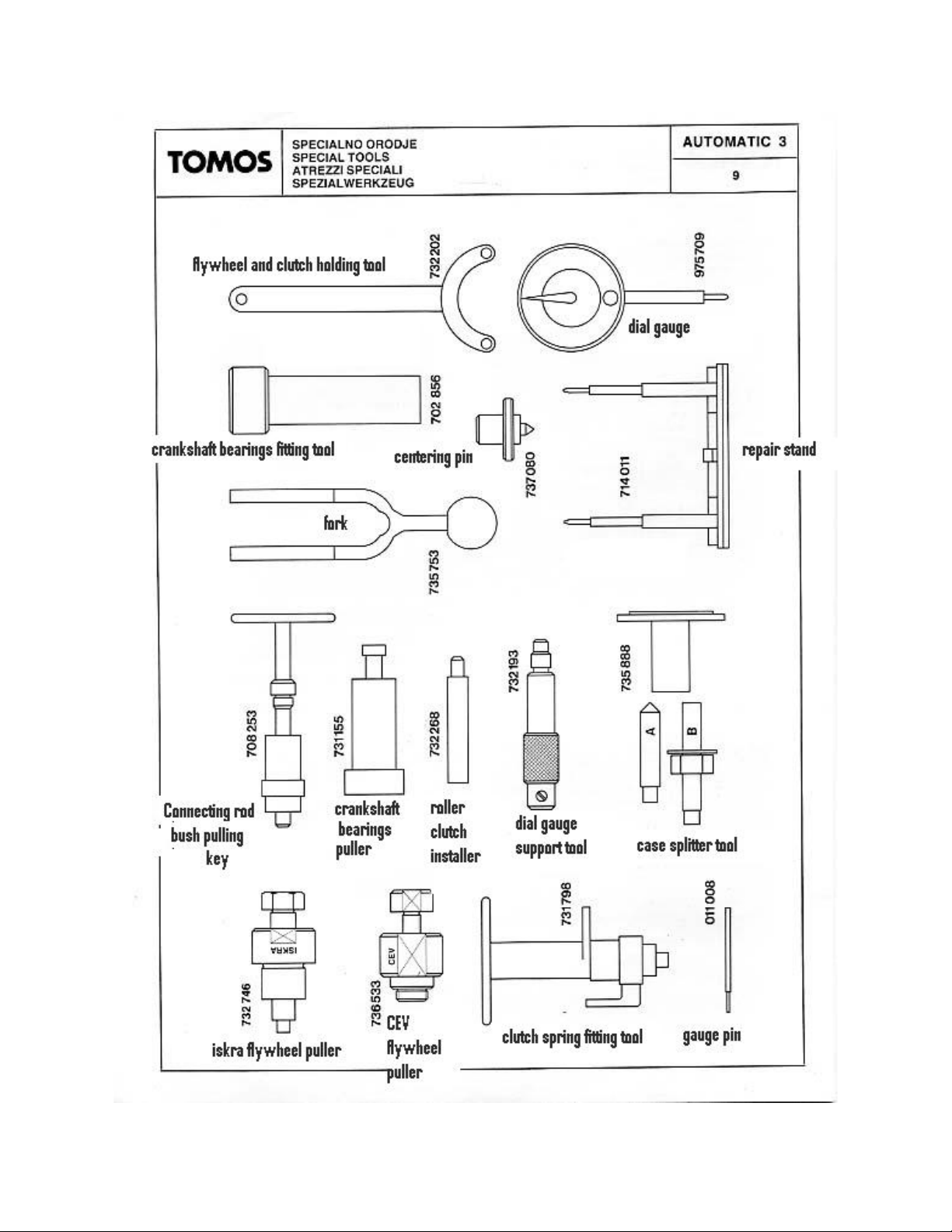
011.008
Gauge pin
702.856
Crankshaft bearings fitting tool
708.253
Connecting rod bush pulling key
714.011
Repair stand
731.155
Crankshaft bearings puller
731.798
Clutch spring fitting tool
732.193
Dial gauge support tool
732.202
Flywheel and clutch holding tool
732.268
Roller clutch installer
732.746
Iskra flywheel puller
735.753
Fork
735.888
Case splitter
736.533
CEV flywheel puller
737.080
Centering pin
975.709
Dial gauge
SPECIAL TOOLS
3
Page 4
Classic Cycles Technical Resources
4 5
Page 5
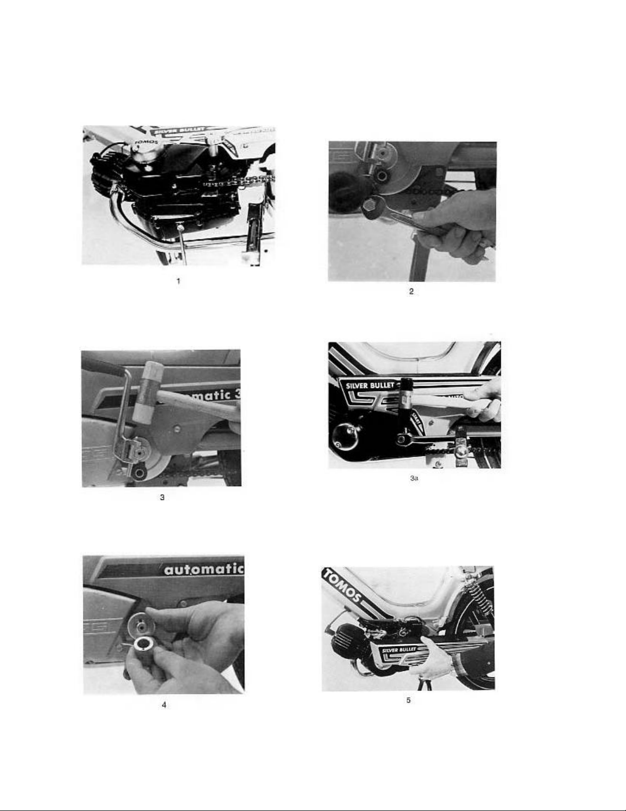
ENGINE REMOVAL
Drain the oil from the gearbox (fig 1)
With 11mm wrench, unscrew the nut and drive
out lever pin (fig 3)
Unscrew the footrest screw with 17mm wrench
(fig 2)
For pedal versions, refer to figures 3a and 4a
Remove the hub, cups and springs (fig 4)
Unscrew the three screws of LH and RH shield
each and detach shields from frame (fig 5)
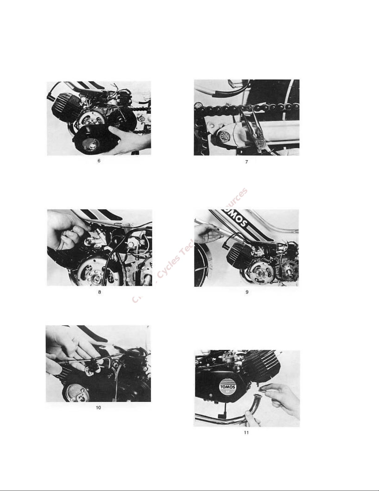
Page 6
Classic Cycles Technical Resources
Unscrew three screws of magneto cover and
detach cover (fig 6)
For oil pump injection refer to chapter OIL PUMP
Remove the chain by removing master link (fig 7)
Unscrew the crown nut and extract control cable
along with throttle piston (fig 8)
Detach all electrical leads (fig 10)
Unscrew bottom screw on control cable cover and
release the spark plug cable (fig 9)
Remove fuel supply line. Remove the two exhaust
manifold bolts, the fixing screw, and remove the
exhaust silencer (fig 11)
6
Page 7
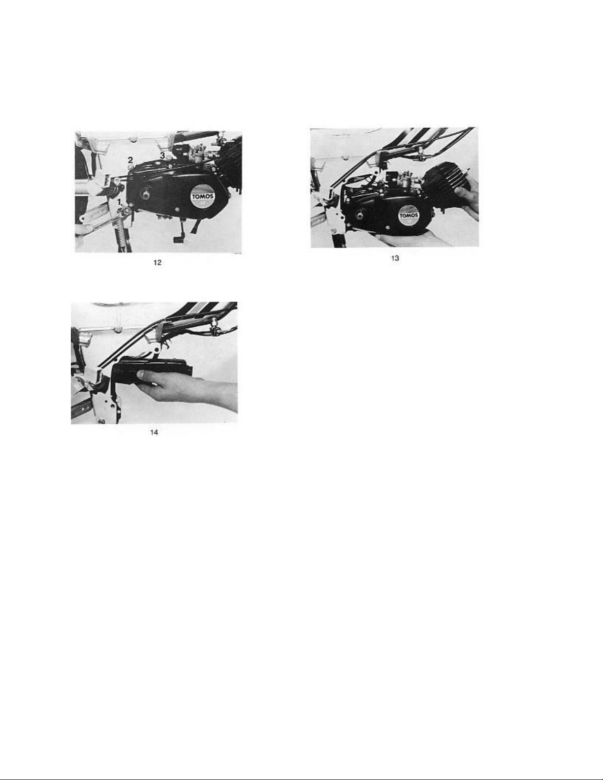
Unscrew all three engine screws with two 13mm
wrenches (fig 12)
Take the intake silencer out of the frame (fig 14)
Hold the engine by hand. Extract top screw (3) and
remove the engine out of the frame (fig 13)
7
Page 8
Classic Cycles Technical Resources
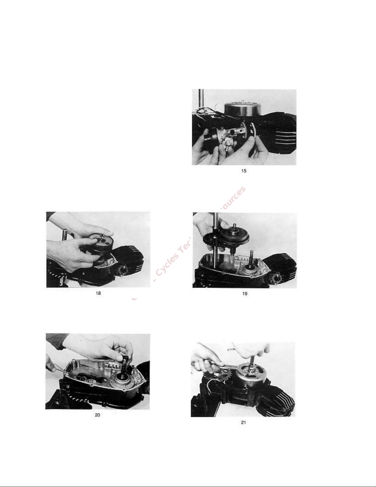
ENGINE DISASSEMBLY
Rotate the engine placed on the stand so that the
Place the engine on the repair stand (special tool).
Remove the carburetor and spark plug (fig 15)
Detach clutch drum and sintered bush (fig 18)
Remove the standard washers on the crankshaft
and on the mainshaft (fig 20)
The pedal shaft and the countershaft are
connected by a starter chain, so both shafts will
have to be taken out together (fig 19)
flywheel magneto is on top. Using the flywheel
and clutch holding tool to hold the flywheel, use a
17mm socket to remove the flywheel nut (fig 21)
8
Page 9

The flywheel is removed with the flywheel puller,
a 19mm, and a 32mm wrench (fig 22)
Make a scriber mark across the bottom of the
stator plate and the crankcase in order to facilitate
the re-timing. Remove the 3 screws and lift the
stator assembly from the engine (fig 23)
Slacken the chain sprocket nut. Using the flywheel
and clutch holder tool and a 30mm wrench,
remove the sprocket nut (fig 24)
With pointed nose pliers, remove the gudgeon pin
spring circlips (fig 26)
Using an 11mm socket, unscrew the 4 cylinder
head nuts. Remove the washers, cylinder head,
cylinder, and base gasket (fig 25)
Press out the gudgeon pin and remove the piston
(fig 27)
9
Page 10
Classic Cycles Technical Resources
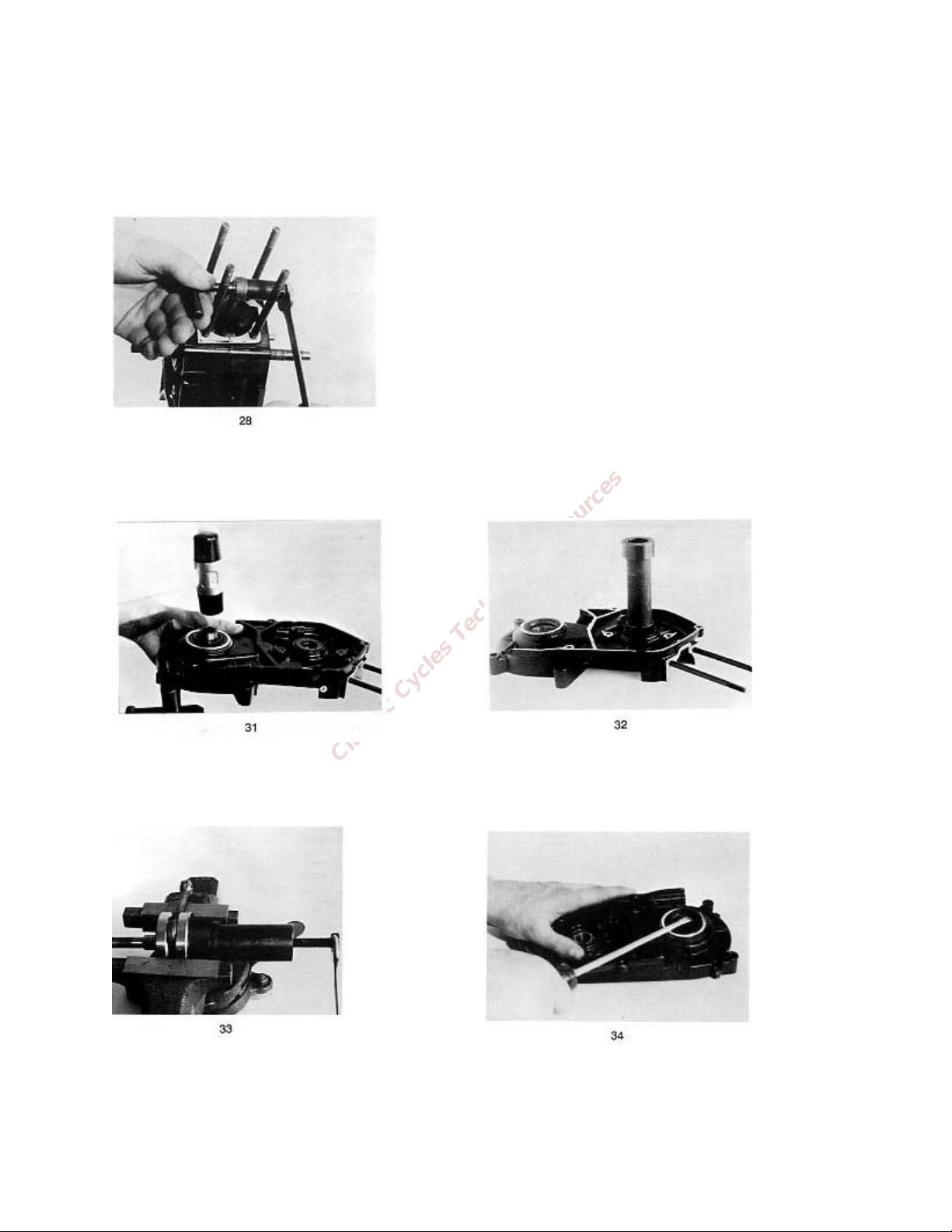
If the brass bushing in connecting rod needs to be
replaced, use the connecting rod bush pulling key,
and replace with a new one using same tool
(fig 28)
Upon installing the new bushing, drill two
lubrication holes according to the holes in the
connecting rod.
The bush as a spare part has inner diameter 9.80
+/- 0.1 mm and it is necessary to ream it out to
increase the inner diameter to 10mm.
Remove the crankshaft and gasket and knock out
the mainshaft (fig 31)
If the ball bearing remains on the crankshaft, use
the crankshaft bearings puller (fig 33)
In case the crankshaft ball bearing remains in the
RH crankcase, use the crankshaft bearings fitting
tool (fig 32)
The mainshaft sealing ring and ball bearing are
pressed out by using a suitable socket (fig 34)
10
Page 11

CHECKING ENGINE PARTS AND ASSEMBLIES
Figure 35
Figure 36
Check both crankcase halves for possible damages or distortions, particularly the joint surfaces, to avoid
later leaking of oil from the gearbox.
Check all bearings. If clearance is noticed, the bearings must be replaced.
Check the crankshaft between the center of a horizontal alignment tool and measure out-of-round on all
the points indicated in figure 35.
Permissible out-of-round should be within 0.01 mm at check pints 2 and 3 and 0.02 mm at check points
1 and 4. Check if the crankshaft conical part is damaged, inspect the thread on semiaxles and the
keyway.
Check piston surfaces for possible damages. With micrometer check piston diameter on points d1, d2,
d3 and d4 at right angles to gudgeon pin and compare the reading with the corresponding group on
piston and in the table (fig 36)
11
Page 12

Classic Cycles Technical Resources
CYLINDER
D (mm, in)
A
B
38.01
+0.01
(1.4964
+0.0024
in)
38.02
+0.01
(1.4968
+0.0024
in)
D1
D2
D3
D4
A
37.95
+0.01
37.91
+0.01
37.87
+0.01
37.85
+0.01
B
37.96
+0.01
37.92
+0.01
37.88
+0.01
37.86
+0.01
D (mm, in)
A
B
38.51
+0.01
38.52
+0.01
D > D
max 0.012 mm
1
Ma x permissible bore taper: 0.006mm
PISTON
L = 50 mm
L= 52.5 mm
L = 55 mm
Piston I. oversize: Ø 38.50mm
The cylinder must be bored and honed as shown in the table:
OVERSIZE CYLINDER
12
Page 13

CHECKING, DISMANTLING, AND ASSEMBLING OF THE CLUTCH
Remove the circlip and separate the 1st and 2nd
Dismantle both clutches. The spring is removed
In this manner, brake strips are released, and all
Press pins out of shoes and check brake strips,
Fix the main pin of the clutch spring fitting tool
To assemble the 2nd speed clutch, turn the device
speed clutches (fig 37)
three shoes can be removed (fig 39)
with a screwdriver (fig 38)
spring inside of shoes and 2nd speed clutch gear. At
first, assemble the 1
st
speed clutch as reversed
order of dismantling. Particular care should be
taken of brake shoes; they must protect each
other from falling out (fig 40)
with the thinner part facing upwards. The spring
joint must be placed in the middle of one shoe.
With the lever of the device, insert the spring into
the shoes groove (fig 41)
over. The clutch hub with gear must be placed in
the way the gear is on the bottom and the gap
between the two shoes fits with the pin. The
manner of mounting the spring is the same as
mentioned before for the 1
st
speed clutch (fig 42)
13
Page 14

Classic Cycles Technical Resources
Dismantling of the needle clutch is necessary only in case of replacement. A new needle clutch is
pressed with special tool “roller clutch installer.” The needle clutch must be pushed with the signed side
towards the center of the clutch drum, or else it may operate in the reverse direction (fig 43)
14
Page 15

DISMANTLING, CHECKING, AND ASSEMBLING OF THE COUNTERSHAFT
Fix the countershaft into a vice and unscrew the
nut with a 19mm wrench (fig 44)
Remove the circlip at the shaft’s toothing (fig 46)
Remove the 2nd speed gear (fig 45)
Unfasten the wire spring and separate a small
chain sprocket with roller cage (fig 47)
Remove the 1
out (fig 48)
st
speed gear and shake the rollers
If troubles appear in the self-locking clutch,
consisting of rollers with 1
st
speed gear hub,
possible damage of the countershaft may be
repaired by grinding the bearing surface for
0.1mm at the most. When most rollers make small
hollows in the hub, the latter can be honed. If
hollows are rather large, the gear should be
replaced.
15
Page 16

Classic Cycles Technical Resources
Reassemble the countershaft in reverse order of
dismantling.
Put the chain sprocket in with cage so that the
Use of grease is not suggested because it may
impede the function of the self-locking clutch.
beginning of the wire spring is turned 90 degrees
left-ward from the spring nose (fig 49). Lock the
wire spring to riveted nose on the 1
st
speed gear
16
Page 17

CHECKING PEDAL SHAFT (kickstart) AND TRANSMISSION CHAIN
If it is necessary to replace the chain sprocket or claw collar on the pedal shaft or kick start, first rmove
the protective ring (fig 50/1) and the spring washer (fig 50/2). During assembly, take care that the
thinner part of the collar is mounted forward or else the brake spring will slide across the chain
sprocket. Check the chain for overtensioning or other damage. In case of damage, the needle bearings
in the main shaft should be replaced with a new complete main shaft (fig 51)
17
Page 18

Classic Cycles Technical Resources
CARBURETOR CHECKING
Dismantle the carburetor into component parts (fig 52 Encarwi or 52a Dellorto). Clean the parts with
carb cleaner and blow them out with compressed air. Check the parts. In case of wear throttle slide or
leakage of float, replace with a new one. When reassembling the carburetor, take care that the float
needle fits the float chamber cover. Slightly oil the air filter with light oil.
FIGURE 52 – ENCARWI CARBURETOR
18
Page 19

FIGURE 52a – DELLORTO CARBURETOR
19
Page 20

Classic Cycles Technical Resources
REASSEMBLING THE ENGINE
When reassembling the engine, replace all seals
With the crankshaft bearings fitting tool, press the
Insert the crankshaft into the LH half of the
Place the mainshaft and a washer on the
Join the right crankcase with the left one, acting as
With the crankshaft bearings fitting tool, insert
and gaskets. All parts of the engine should be
thoroughly cleaned and lightly oiled. All gaskets
should be given a light coat of grease to insure
better fit and seal.
crankcase using the splitter. Through the splitter,
screw the device on the crankshaft. With an 11mm
and a 24mm wrench, place the crankshaft in the
crankcase (fit 54)
crankshaft ball bearings into both crankcase halves
(fig 53)
mainshaft needle bearing. Insert the fork between
the two halves of the crankshaft (fig 55)
follows: (1) Press the two crankcases by hand and
then lightly tap them together with a mallet
(2) Insert the 6 screws in the inner holes and 2 in
the outer holes. Slowly tighten the screws (fig 56)
both crankshaft seal rings.
WARNING: The LH carter seal ring is facing
towards the connecting rod, while the RH side is
opposite.
20
Page 21

Check that the crankshaft turns freely. Insert pedal
shaft or kick shaft together with countershaft and
The claw collar brake spring must seat in the
chain (fig 57)
recess in the RH half of the crankcase. Place
washer 209.005 and bush 209.072 on the
crankshaft (fig 58)
Incorporate the clutch drum with mounted 2nd
speed clutch (fig 59)
Incorporate 1st speed clutch and protective
washer. With the flywheel and clutch holding tool,
lock the nut with a 19mm wrench. Torque to
25Nm. Clearance between shoes and clutch drum
rim is approx. 0.4 mm. Axial clearance of the clutch
drum is from 0.1 mm to 0.3 mm by means of
inserting the adjusting thrust washer of 0.3 mm or
0.5mm under the clutch (fig 61)
Handle the roller clutch carefully and if it is
necessary, turn the drum only counterclockwise
(direction of free rotation). Place the trust washer
under the clutch (fig 60)
21
Page 22

Classic Cycles Technical Resources
Before securing the nut with washer, it is
necessary to check the proper function of the
sprocket with the flywheel and clutch holding tool.
assembly. Firmly hold the 2
with the left hand and the clutch drum with the
right hand. When the clutch drum rotates
counterclockwise, both clutches idle. When it
rotates clockwise, the motion is transmitted to the
crankshaft (fig 62)
nd
speed driven gear
Fit the gasket and cover and tighten 7 screws with
torque of 10Nm (fig 63)
Make sure the piston rings are installed properly
by aligning them with the stationary pins mounted
in the ring grooves of the piston. Compress the
piston rings and mount oiled cylinder (fig 65)
Turn the engine on the stand 90 degrees. Clean
residue of crankcase gasket. Mount the piston so
that the arrow sign on the top of the piston is
facing the exhaust side of the cylinder (fig 64)
Mount the cylinder head, washers, and nuts.
Tighten them in an X pattern, torque to 12 Nm.
Turn the engine so that the magneto flywheel side
is on top. Install the stator base plate. If necessary,
slightly oil the felt inset piece of the base plate.
When mounting the magneto flywheel, take care
when positioning it. The groove on the flywheel
hub and the woodruff key on the crankshaft must
coincide. Fit the washer and nut, lock the flywheel
with the flywheel and clutch holding tool, and
tighten the nut to a torque of 30 Nm.
Place the distance bush, chain sprocket, and
protective washer on the main shaft and tighten
the nut with a 30 mm wrench. Lock the chain
22
Page 23

ADJUSTING THE CONTATCT GAP AND IGNITION ADVANCE
These two operations are interrelated and proceed as follows.
-Screw the dial gauge support tool and the dial gauge into the spark plug hole.
-By rotating the flywheel, put the piston at TDC and set the dial gauge to zero.
-The breaker points are fully open at TDC. Check and if necessary, reset the gap between 0.35 and 0.45
mm (fig 66)
-Rotate the flywheel in the clockwise direction until the breaker points connect. With a test light, buzzer
or Ohm meter, determine when a connection is made. The testing device must be connected to the
short circuit (black) wire and to the ground of the engine (fig 67)
-At the moment of connection of the points, the test battery light will glow brightly, the buzzer will
change the acoustic frequency, or the Ohm meter will show approximately zero Ohms. On the dial
gauge, read off the value in mm of the ignition advance which must be from 1.8 to 2 mm BTDC.
-In case of excessive advance, the stator base plate should be rotated in the direction of engine rotation
(see arrow on flywheel). In case of insufficient advance, turn the plate in the opposite direction.
23
Page 24

Classic Cycles Technical Resources
OIL PUMP
Note: When fitting the magneto cover on oil pump
cut off, which may lead to breakdown of the unit.
After assembly or repair of models with oil pump, you must keep to the following instructions
The pump is connected to the magneto nut on the
crankshaft by a special clutch (fig 68)
Pour approximately 1 liter gas mixture in the ratio
of 50:1 (2% oil) into the fuel tank and start the
engine. Let the engine run for about 5 minutes so
as to make the oil pump push oil into the engine.
Fill up the tank with regular gas.
Unscrew the bleed screw on the oil pump and wait
until oil from the tank under the seat flows to the
pump. The screw is then screwed on (fig 69)
Ensure that the oil level in the oil tank does not fall
under the marking MIN (fig 70). Pay special
attention to the routing of the oil lines to and from
the oil pump. If the outflow line is crimped, oil will
not reach the carburetor, causing engine damage.
models, make sure the oil pump seat axis lines up
with the crankshaft axis. Use the centering pin
attached to the magneto cover (fig 71) for this
purpose. When the center has been found, push
the cover by hand onto the crankcase (which is
made possible by the spring in the centering tool)
and fix the cover by screwing it down.
Major deviations from the center result in the
clutch damage, and this, in turn, causes the oil
pump drive stoppage. The lubrication of the
cylinder, piston, and crankshaft of this unit is thus
24
Page 25

MAGNETO SETTINGS AND ELECTRICAL EQUIPMENT
The voltage regulator should be checked when bulbs blow frequently. During the check, the engine
should be operating and the lights switched off-on, alternatively. The voltage should always read 12+/-
0.5 V. Before replacing the regulator, make sure the improper operation is not due to bad grounds.
The direction indicator relay should be checked within the wiring system. Previously check the bulbs
and direction indicators switch.
The STOP switch should be checked by a pilot bulb or OHM-meter. When replacing the switch, make
sure the new one is identical to the replaced one wince there are two types of STOP switches (those that
are switched on in neutral position, and those that are switched off in neutral position)
Electric wiring and combination switches are checked according to the wiring diagram. Check the
magneto components both within the wiring system and separately.
The flywheel should be checked by visual inspection for mechanical damage and proper cone fit. Check
deflection by help of the crankshaft. The maximum permissible axial deflection amounts to 0.1 mm and
radial deflection to 0.3 mm.
To check the capacitor it should be separated from other electrical components of the magneto. Check
the capacitor capacitance by means of a capacitance meter and the ability of the capacitor to retain an
electric charge.
NOTE: Caution is recommended in handling the non-insulated parts since there is a possibility of an
electric shock. The capacitor should, therefore, be discharged by connecting the two contacts.
Contact breaker: check the contacts and the cam nose for wear. Insert insulating mass between the two
breaker contacts and by an OHM-meter make sure the parts are electrically disconnected (there exists a
possibility of uncture on the bearing bush or fixing bolt insulation)
The ignition coil both external and internal can only be checked if a special mototester is available. The
checking procedure is laid down by the manufacturer of this device. If this is not available, a possible
fault can be established by replacing a truly good sample coil for the existing coil.
The lighting coil should be checked with engine in operation (2000-3000 RPM). To check the coil, use a
voltmeter and an approximate bulb of the same rated power (W) as the magneto.
25
Page 26

Classic Cycles Technical Resources
26
Page 27

27
Page 28

Classic Cycles Technical Resources
28
Page 29

29
Page 30

Classic Cycles Technical Resources
te
Yellow
Brown
Black
Brown
Whi
30
Page 31

MOTORCYCLE PARTS & ACCESSORIES
Tomos Motorcycle History & Technical Specifications
Motorcycle Parts & Accessories
Dirt Bike Parts & Accessories
Harley Davidson Parts & Accessories
Motorcycle Helmet Closeout Sale
Japanese Motorcycle Original Equipment Parts
Save On All Motorcycle Tires
Motorcycle Jacket Closeout Sale
High Visibility Motorcycle Safety Gear
Cycle Gear – Free Shipping
Women's Motorcycle Riding Gear
Free Shipping On All Motorcycles
Save Up To 80% On All Car Parts
 Loading...