

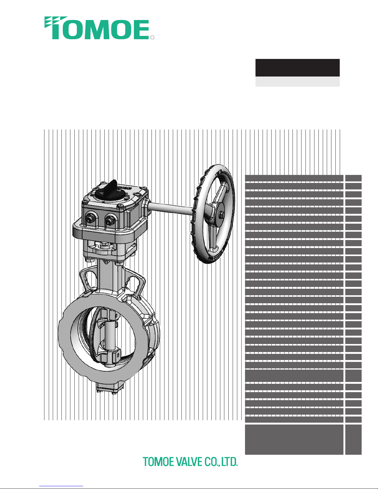
Tomoe 304YA Instruction Manual
R
INSTRUCTION MANUAL
High Performance Butterfly Valve
304YA
Contents
Page
FOR YOUR SAFE USAGE 1
1. PRODUCT FEATURES 2
1. 1 About the Product 2
1. 2 Standard Specications 2
1. 3 Pressure - Temperature Rating 3
2. STRUCTURE 4
2. 1 Expanded View and Part List 4
3. PRECAUTIONS FOR USE 5
3. 1 Safety Measures 5
3. 2 Transportation and Storage 6
3. 3 Installation and Working Environment 7
3. 4 Installation Precautions 9
3. 5
Precautions for Safe Handling After Installation
12
3. 6 Maintenance 13
4 INSTALLATION 15
4. 1 Installation Procedure 15
5 MAINTENANCE 17
5. 1.
Seatring Disassembly/Assembly Procedures
17
5. 2 Removal of Valve Body and Actuator 18
5. 3
Disassembly/Assembly Procedures of Gland area
19
5. 4
Assembly Procedure of Valve Body and Actuator
20
5. 5
Valve Body Full-Close Position Adjustment Procedure
21
6. Piping Data 22
6. 1 Minimum Inner Pipe Diameter and Disc
Protruding Dimension at Full-open Position
22
6. 2 Applicable Pipes 22
6. 3 Piping Gasket Dimensions 23
6. 4 Piping Bolt Sizes 24
7. TROUBLESHOOTING 25
7. 1 Troubleshooting 25
WARRANTY PERIOD / SCOPE OF WARRANTY
AND INDEMNITY
/
CHARGED REPAIR SERVICE
AND SUPPLY OF DISCONTINUED PARTS
/
28
REPLACEMENT TIMING OF SPARE PARTS
/
APPLICABLE APPLICATION CONDITIONS
1
FOR YOUR SAFE USAGE
The following instructions should always be followed.
Thank you for purchasing our products.
For safe use of our products over long periods of time, please read this instruction manual (hereinafter "this document") thoroughly before use, and use the products properly in accordance
with the contents.
The following instructions are for long-lasting service of High Performance Butterfly Valve 304YA
(hereinafter "this product") without loss or injury.
■
In this document, the level of danger or damage caused by neglecting these cautions
will be indicated as follows:
This mark indicates "possibility of death or serious injury".
This mark indicates "possibility of injury to personnel or physical damage
only".
■
In this document, the following marks will indicate particular points for your attention.
This mark indicates items that "you must not do".
This mark indicates items "you must do".
■
Requests
Be sure to read this document before carrying out transportation, storage, piping installation, operation and main-
tenance work.
This document does not describe all the assumed conditions concerning transportation, storage, piping installa-
tion, operation and maintenance of this product. If you have any questions, please contact our sales department.
Reference values and limit values for operation, maintenance and inspection specified in this document have
been determined in consideration of maintenance management of this product. This product should be used
within the range of the reference values and the limit values.
This product should be used only with the dedicated actuator installed when shipped. Do not use this product
with other actuators.
Be sure to store this document in a readily accessible place for future reference after installation and start of
operation. When a staff in charge is changed, information on the storage place of this document and operation
should be communicated to the next staff.
If this product gets dented or scratched on impact, to ensure safety stop use of the product and replace it.
Details of this document are subject to change without notice.
WARNING
CAUTION
2
1. PRODUCT FEATURES
1. 1 About the Product
This product is a double eccentric butterfly valve, which controls fluid by 90-degrees rotation of the disc.
The valve can be fully opened or closed. In addition, an intermediate valve opening can be used for fluid control.
1. 2 Standard Specifications
<Table-1> 304YA Standard Specifications
Valve Model 304YA
Valve Type Double eccentric (Wafer)
Valve nominal size
1 1/2, 2, 2 1/2, 3, 4, 5, 6, 8, 10, 12inch
40, 50, 65, 80, 100, 125, 150, 200, 250, 300 mm
Max. allowable working pressure 1.0 MPa
Allowable seat leakage standard ISO 5208 leakage rate A (tight shut-off)/ JIS B 2003
-2013
rate A
Flow direction Retainer side pressurization
Applicable
standards
Face to face
dimensions
JIS B 2002
-1987
(series 46)/ ISO 5752 wafer butterfly valve (short)
Applicable flange
connection
JIS 5K / JIS 10K / ASME / ANSI CLASS 150
Top flange In compliance with ISO 5211
Standard
materials
Body SCS13A FCD450
Disc SCS13A
Shaft SUS630 SUS420J2
Seatring RPTFE (Carbon and graphite contained)
Gland packing RPTFE (Graphite contained)
Maximum temperature range -29°C - 200°C -20°C - 200°C
Ambient temperature range
1T -20°C - 80°C
2U -10°C - 80°C
7E, 7F, 7G -10°C - 60°C
3U, 3K 0°C - 80°C
4I ,4J -10°C - 50°C
Test pressure
Body Shell Working pressure × 1.5 (Water pressure)
Seat leakage Working pressure × 1.1 (Pneumatic pressure)
Actuator
Lock Lever 1T 40 mm - 150 mm
Worm gear 2U 40 mm - 300 mm
Pneumatic cylinder
7E 40 mm - 300 mm
7F, 7G 40 mm - 200 mm
3U, 3K 250 mm, 300 mm
Motorized 4I ,4J 40 mm - 300 mm
Maximum average flow velocity
in piping (Limit value)
6 m/s or less (Valve full-open, continuous operation)
Body color FCD450-body only : Modified silicon resin coating Munsell N7 (Gray)
3
1. 3 Pressure - Temperature Rating
[Fig.-1]
Case of FCD450-body :
-4°F or over ~ less than 392°F
Case of SCS13A-body :
-20°F or over ~ less than 392°F
0 50 100
-29 -20
150
200 250
Temperature [℃]
0.2
0.4
0.6
0.8
1.0
Pressure [MPa]
8
3
13
14
15
16
22
10
11
8
1
21
7
20
5
12
2
17
4
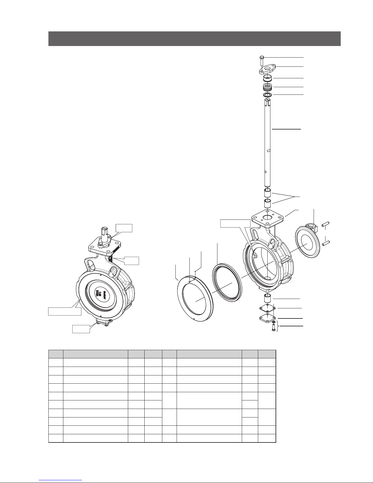
2. STRUCTURE
2. 1 Expanded View and Part List
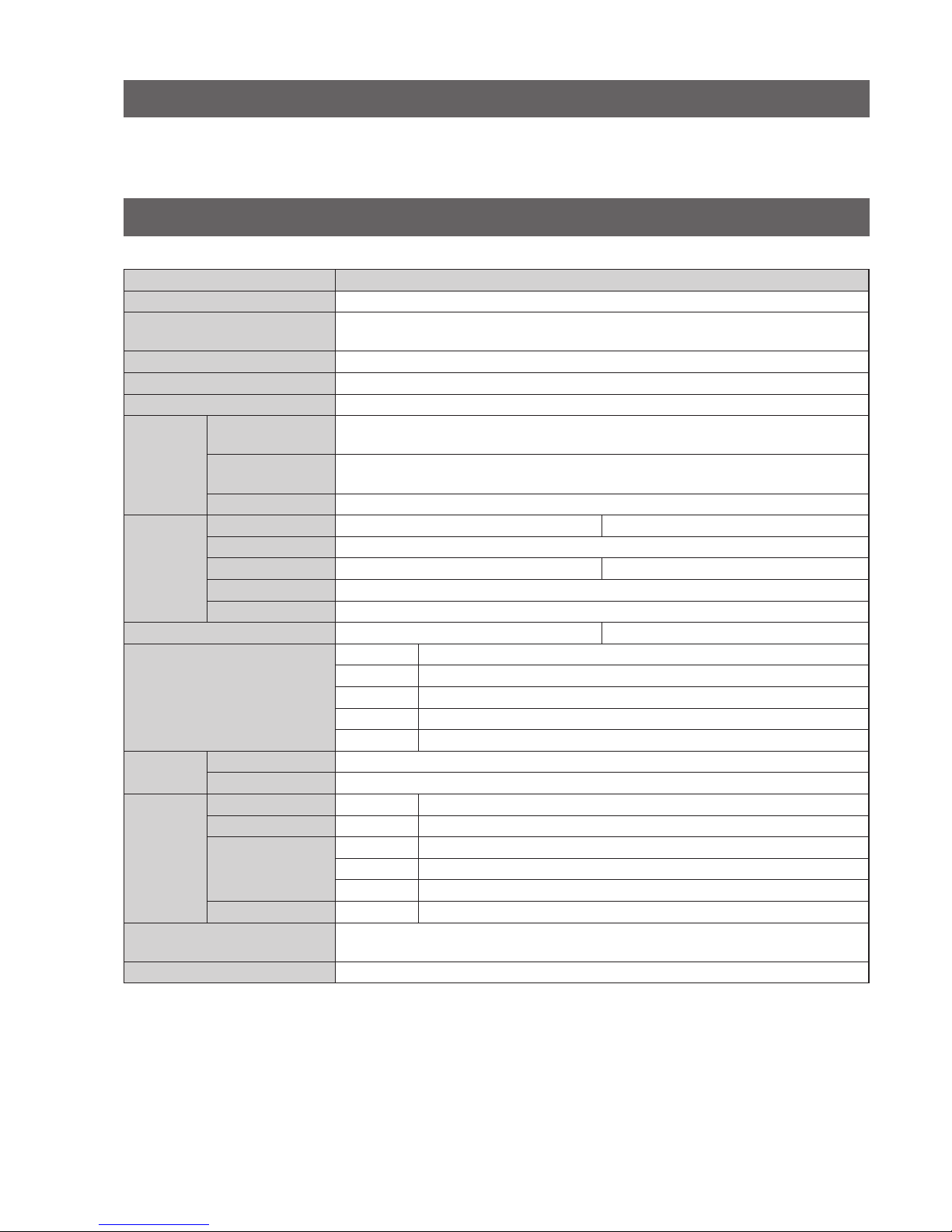
<Table-2> 304YA Parts List
No. Description Q'ty
Remarks
No. Description Q'ty
Remarks
1 Body 1 14 Gland packing 1 set
2 Disc 1 15 Rough gland 1 set
3 Shaft 1 16 Gland flange 1
5 Seatring 1
17 Hexagon bolt 2
7 Seatring retainer 1
20 Ball
2
*1
8 Shaft bearing 3 3
*2
10 Bottom cover 1
21 Hexagon socket set screw
2
*1
11 Bottom gasket 1
3
*2
12 Taper pin 2 22 Hexagon bolt 4
13 Packing retainer 1 22 Spring washer 4
*1 For nominal sizes of 40 mm to 100 mm, *2 For nominal sizes of 125 mm to 300 mm
Remarks: The indicates recommended spare parts. They are supplied as “Seatring set” with a small hexagonal spanner to
remove hexagon socket set screw (P.No.21).
[Fig.-2] [Fig.-3]
Gland
Neck
Flange surface
Bottom
Disk stopper
5
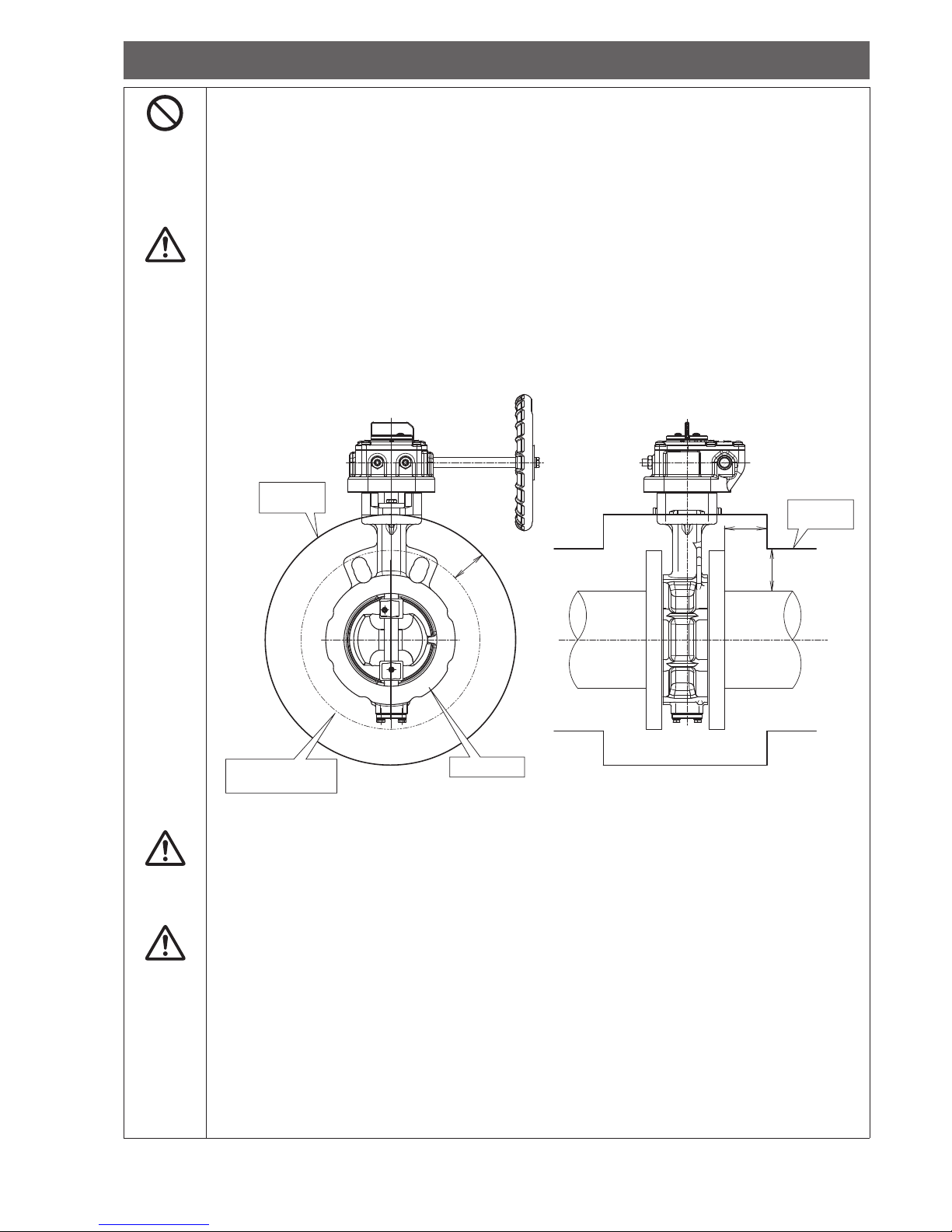
3. PRECAUTIONS FOR USE
3. 1 Safety Measures
WARNING
3.1.1 Handling of this product
1) This product should be assembled, operated, maintained, etc. by personnel who have read
this document thoroughly and understood the contents well.
2) The work should be performed while wearing protective gear, such as a helmet, safety belt,
protective glasses, working gloves and safety shoes, in accordance with laws and regulations,
and safety provisions of business establishments.
3) Do not stand or place heavy objects on this product, as this may cause the product to be damaged, resulting in falling accidents.
WARNING
3. 1. 2 Safety check
Equipment should only be dismantled after the following points have been checked to ensure safety.
1) Safety precautions for this product, such as prevention against falling of parts, material or
other accidental happenings, have been taken.
2) The surface temperatures of the product, flanges, and pipes are at a level where the surfaces
can be touched.
3) The pressure in the piping is the atmospheric pressure, and fluid has been drained out from
the inside of the piping.
4) When the fluid flowing through the piping is toxic, flammable or corrosive, adequate safety
measures have been taken.
5) Energy sources of the related facilities, such as power supplies and air sources, have been
shut off.
6) No fluid harmful to the human body is adhered on this product or peripheral piping.
Before restarting of the unit, check the following items.
1) The product and the actuator are secured firmly.
2) There is no failure or damage to the appearance, or loss of parts.
3) Tools have not been left on the product or pipes.
4) Nothing hinders operation of the product (operation of the lever and handle, opening/closing of
the valve).
5) Safe evacuation procedure is already introduced in case of unexpected movements, leakage,
etc.
WARNING
3. 1. 3 Water hammer and steam hammer
1) Should be check whether there is water hammer and steam hammer during operation.
If water hammer or steam hammer occurs, this product and peripheral piping materials may
be damaged.
2) For a lever type, do not open or close the valve abruptly because it causes water hammer.
3) For a pneumatic cylinder valve with a speed controller, the speed controller is fully opened
when shipped. If the opening/closing time is short, water hammer or steam hammer may occur, resulting in damage of the product. Therefore, be sure to adjust the opening/closing time.
4) Note that piping conditions may cause water hammer or steam hammer which has an influence on the product by stopping pump operation, opening/closing operations of other valves.
WARNING
3. 1. 4 Cavitation
Design should be performed to prevent cavitation.
This product can be operated at the intermediate valve opening (Opening: 30° or more). However, if
abnormal noise or vibrations are generated by the product or peripheral piping, cavitation may have
occurred.
When this product is used for long periods of time in this state, the product or piping materials may
be damaged. Therefore, prevent cavitation by changing the valve opening, pressure, flow rate, etc.
6
3. 2 Transportation and Storage
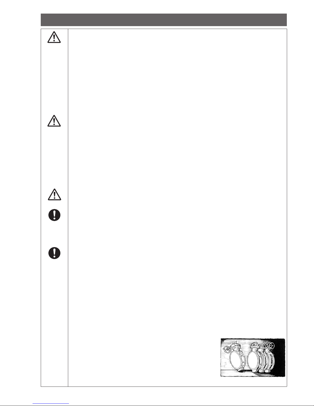
WARNING
3. 2. 1 Transportation and Transfer
1) Products with large mass (approx. 20 kg or more) should be transported using equipment or a
machine, not by manpower alone. See the catalog, product drawings, etc. issued by our company for details on the mass of this product.
2) Qualified personnel should perform work with a forklift or a crane, or slinging work in accordance with laws and regulations, and safety provisions of business establishments. In addition,
observe section 「3. 2. 2
3) Protect this product sufficiently before transportation so that it is not damaged. Damage
causes leakage or corrosion.
4) Use containers for ocean transportation. If containers are not used, this product becomes deteriorated due to salty sea breeze.
5) Use a covered vehicle for inland transportation to avoid exposure to wind and rain.
If an uncovered vehicle is used, cover the product with a protective tarp.
6) Do not throw the product and do not apply a heavy load.
WARNING
CAUTION
3. 2. 2 Drop and falling
1) At lifting up and slinging work, perform the work while paying thorough attention to safety.
E.g., check the mass well in advance, and use a lifting tool or equipment corresponding to the
mass, but do not stand under a hung load.
2) Transportation shall be performed under sufficient illumination to secure safety of scaffolding.
Avoid work on unstable pipes, etc.
3) At unloading or transportation between warehouses, this product should be held properly to
prevent it from falling and being damaged.
4) Do not suspend or hoist this product by hanging a hook on the handle. Otherwise, the product
may be damaged or fall, which is very dangerous. Suspend the product by tying down a wellbalanced position, such as the neck section of the valve body, with material that does not damage the product, such as nylon sling.
3. 2. 3 Packing state
This product is shipped in the full-close position, except for the single-acting type air-to-close pneumatic cylinder. Be careful not to damage the edge of the disc, Seatring, and flanges.
3. 2. 4 Unpacking
1) Unpack this product immediately before installing it to the piping. Do not leave the product
unpacked for long periods of time to prevent adherence of dust and harmful substances and
deterioration due to ozone or ultraviolet rays. Otherwise, degradation in performance, contamination, discoloration or material deterioration may occur.
2) Be careful not to damage this product with a cutter, etc. when unpacking.
3. 2. 5 Storage
Store this product as follows to prevent degradation in performance, contamination, discoloration,
and material deterioration.
1) Store this product in a place with no dust or water droplets while avoiding direct sunlight, high
temperatures and humidity.
2) Store this product indoors (ambient temperature: 0°C - 50°C, humidity: 70% or less) without
removing the cardboard packaging or the protective material attached to the valve body.
3) For cardboard packaging, high humidity may reduce the strength of the box and the packaging
may be broken, which may result in damage of the product. Be adequately careful not to get
the packaging wet.
4) Do not store this product in an atmosphere that contains corrosive gas. Otherwise, the parts
may be subject to corrosion, resulting in an impairment of functions.
5) Do not drop, overturn or vibrate this product, and do not apply a heavy load to the product during storage. Otherwise, functions may be impaired.
6) Do not stack this product at storage. A load collapse may occur, which causes damage to personnel and/or the product. (Refer to section 3. 2. 2.)
7)
Store this product in the full-close position. Open and close the product about once every three months.
8) Store this product while no load is applied to the actuator. Otherwise, the handle shaft, etc. may be deformed.
9) For long-term storage, apply Ferro-Guard (Ferro-Guard
#1009, US Ronco Laboratories, INC.) once a year to the
plated parts (indicator, bolts, nuts, handle shaft, etc.).
[Fig.-4]
7
3. 3 Installation and Working Environment
WARNING
3. 3. 1 Installation location and working environment
For installation locations, necessary work space should be provided for expected work and maintenance, such as operation of the actuator, wiring and piping.
In the following installation locations or working environments, special actions, such as compliance
with laws and regulations, may be required in some cases as well as functional conformance to
specifications. If there are any questions, please contact our sales department at the planning stage.
1) Special working environments which are not specified in the specifications
2) In the case where substantial damage to human beings, assets, environments, etc. is predicted if this product fails
E.g.: Facilities related to the High Pressure Gas Safety Act, facilities related to the Industrial
Safety and Health Act, Nuclear power related facilities, medical facilities, vehicles, etc.
CAUTION
3. 3. 2 Atmosphere of installation location
The following measures should be taken depending on the atmosphere of the installation location.
1) Locations which are exposed to gas containing salt, corrosive gas, chemical solution, organic
solvent, steam, salt water, etc. should be avoided.
2) If there is a possibility that this product is exposed to direct radiant heat or chemicals, the
product and attachments should be protected with covers.
3) Do not submerge this product. When it is installed in a place that is usually exposed to water,
such as near a cooling tower, protect the product and attachments with covers.
4) When this product is installed in a salt damage zone, take measures against salt damage.
3. 3. 3 Temperature of installation location and working environment
Using this product out of the allowable working temperature range causes thermal degradation or
hardening of Seatring and O-rings, faulty operation due to thermal expansion of parts or difference
of thermal shrinkage, etc.
1) The ambient temperature of the installation location should be within the ambient temperature
range of the specification (section 「1. 2).
2) When this product is exposed to direct sunlight, maintain the working temperatures of the
product and the actuator under the upper limit.
3) This product should be kept away from heat sources, and should be installed in a location
whose temperature is within the specified ambient temperature range. Not that temperature
near a motor, an engine, an air compressor, a boiler, etc. may exceed the specified ambient
temperature range.
4) When this product is used in an environment where the temperature of the internal fluid
changes significantly, note that leakage tends to occur due to difference in the coefficients of
thermal expansion of materials.
CAUTION
3. 3. 4 Vibration and impact at installation location
The following measures should be taken if there are vibrations or impact at the installation location.
1) When this product is used in the following conditions, check vibration or impact conditions,
such as acceleration values, and contact our sales department.
Location where excessive vibration or impact of more than 9.8 m/s
2
is expected to be ex-
erted
Location where vibration or impact is exerted continuously
2) Installation sections and connecting sections, etc. should be locked to secure and fasten them
firmly.
3) Vibration isolation measures should be taken to reduce vibrations or impact on the machine.
Piping should be secured with supports, or vibration isolation material should be installed.
4) Joints should be checked periodically against looseness and deformation. In case of abnormal
conditions, bolts should be retightened or parts should be replaced. Coming off of the bolts
may cause falling off or rotation in an unexpected direction of this product.
5) For a gear type, the handle may rotate due to vibrations. Take measures to secure the handle, such
as handle lock, when necessary. Handle lock can be provided as optional at time of order.
8
3. 3 Installation and Working Environment
(Continued)
3. 3. 5 Removal and replacement of this product and the actuator
1) The seat sealing performance of this product depends on the full-close adjustment mechanism
of the actuator. Therefore, make alignment marks before removing the actuator, and take care
that its position is not changed at reassembly.
2) Do not remove the actuator and replace it with other actuators or modify the actuator. When
the actuator is replaced or modified, the warranty is no longer applicable.
CAUTION
3. 3. 6 Precautions for installation of thermal insulating material for the valve
If a thermal insulation thickness is 50 mm or less from the pipe outer diameter and the flange outer
diameter, the gland can be retightened. Leakage of fluid from this product to the outside may happen due to reduction in the tightening force as a result of stress relaxation of the packing during
commissioning and operation. In consideration of leakage, install the thermal insulation so that the
lever and the handle can be operated unhindered.
In addition, install the thermal insulation so that the indication of opening can be seen. For a gear
actuator, there is an option to extend the indication of opening. Please contact our sales.
CAUTION
3. 3. 7 Condensation
Condensation may occur in the actuator when the temperature of the actuator is different from the
ambient temperature.
There is an option to prevent condensation of the actuator. Please contact our sales.
CAUTION
3. 3. 8 Precautions for selection
1) This product has a structure where the body gets wet in contact with the fluid. Pay attention to
corrosion of the body due to the fluid used. Especially, Be careful to FCD450.
2) A pressure direction (flow direction) is specified on the body. Use with pressurization in the opposite direction is not guaranteed.
3) The pressure test is performed with water at the factory. When the fluid is gas/vapor and a little
external leakage is a problem, please contact our sales department.
4) This product use RPTFE for seat ring, so it is very weak for rust or jam and easy to get injured.
If get injured, happen leak at during an early stage.
5) If used fluid be powder or slurry, it is piled up on stopper or seal surface for disc. And lifetime
for product might be shorter.
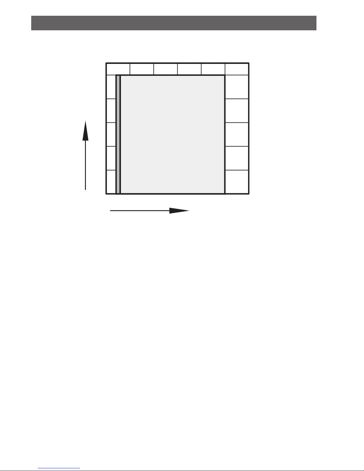
50
50
50
Thermal
insulation
Outside diameter of
the flange
Thermal
insulation
Valve body
[Fig.-5]
 Loading...