

Tommy Bahama PRADO TB310AS00, PRADO TB310DBZ00 Owner's Manual
xxxxxxxxxxxxxxxxxxxxxxxxxxxxxxxxxxxxxxxxxxxxxxxxxxx
xxxxxxxxxxxxxxxxxxxxxxxxxxxxxxxxxxxxxxxxxxxxxxxxxxxxxxxxxxxxx
xxxxxxxxxxxxxxxxxxxxxxxxxxxxxxxxxxxxxxxxxxxxxxxxxxxxxxxxxxxxx
xxxxxxxxxxxxxxxxxxxxxxxxxxxxxxxxxxxxxxxxxxxxxxxxxxx
Net Weight:
25.5 Lbs.
Part No. F40BP73890000 Form No. BP7389
READ AND SAVE THESE INSTRUCTIONS
TB310AS00
Antique Silver with
Weathered Oak Blades
TB310DBZ00
Distressed Bronze with
Weathered Oak Blades
PRADO
™
Damp Location
Ceiling Fan Owner's Manual
Model Numbers
BP7389 Prado TB310 2/1/09 2:29 PM Page 1
WARNING: To avoid fire, shock, and serious personal injury, follow these instructions.
Safety Instructions
1. Read your owner’s manual carefully and keep it for future reference.
2. Before servicing or cleaning unit, switch power off at service panel and lock service
panel disconnecting means to prevent power from being switched on accidentally.
When the service disconnecting means cannot be locked, securely fasten a warning
device, such as a tag, to the service panel.
3. Be careful of the fan and blades when cleaning, painting, or working near the fan.
Always turn off the power to the ceiling fan before servicing.
4. Do not put anything into the fan blades while they are turning.
5. Do not operate reversing switch until fan blades have come to a complete stop.
Additional Safety Instructions for Installation
1. To avoid possible shock, be sure electricity is turned off at the fuse box before wiring,
and do not operate fan without blades.
2. The installation is to be in accordance with the National Electrical Code, ANSI/NFPA
70-1999 and Local Codes. Use the National Electrical Code if Local Codes do not exist.
The ceiling fan must be grounded as a precaution against possible electrical shock.
Electrical installation should be made or approved by a licensed electrician.
3. The outlet box and joist must be securely mounted and capable of reliably
supporting at least 50 pounds. Use only U.L. outlet boxes listed as “Acceptable for Fan
Support”, and use the mounting screws provided with the outlet box. Most outlet
boxes commonly used for support of light fixtures are not acceptable for fan support
and may need to be replaced. Consult a qualified electrician if in doubt.
4. The downrod furnished with the fan provides the minimum recommended floor to fan
blade clearance for an 8 foot ceiling.
5. The fan must be mounted with the fan blades at least 7 feet from the floor to prevent
accidental contact with the fan blades.
6. Follow the recommended instructions for the proper method of wiring your ceiling
fan. If you do not know enough about electrical wiring, have your fan installed by a
licensed electrician.
NOTE: This fan is suitable for use with solid-state speed controls.
WARNING: To reduce the risk of fire or electric shock, this fan should only be used with
fan speed control Model No. UC7067RC, manufactured by Rhine Electric Co., Ltd.
WARNING: This product is designed to use only those parts supplied with this product
and/or any accessories designated specifically for use with this product by Emerson
Electric Co. Substitution of parts or accessories not designated for use with this product
by Emerson Electric Co. could result in personal injury or property damage.
WARNING: To reduce the risk of personal injury, do not bend the blade flange when
installing the blade flanges, balancing the blades or cleaning the fan. Do not insert foreign
objects in between rotating fan blades.
WARNING: To reduce the risk of electric shock, this fan must be installed with an
isolating wall control/switch.
!
WARNING
DATE CODE:
The date code of this fan may be found on the box, stamped in ink on a white label.
You should record this data above and keep it in a safe place for future use.
2
BP7389 Prado TB310 2/1/09 2:29 PM Page 2

3
THIS FAN IS SUITABLE FOR DAMP LOCATIONS
SUCH AS COVERED PORCHES, COVERED PATIOS, AND COVERED
DECKS...ANYWHERE THERE IS A ROOF OVERHEAD.
This Manual is Designed to Make it as Easy as Possible for You to
Assemble, Install, Operate and Maintain Your Ceiling Fan
Do not install or use fan if any part is
damaged or missing. Call Toll-Free:
1-800-654-3545
!
WARNING
This product is designed to use only those
parts supplied with this product and/or
any accessories designated specifically for
use with this product by Emerson Electric
Co. Substitution of parts or accessories not
designated for use with this product by
Emerson Electric Co. could result in
personal injury or property damage.
!
WARNING
Tools Needed for Assembly
One Phillips head screwdriver
One wire stripper
One stepladder
Three 60-watt (maximum) candelabra
base bulbs
Materials
Wiring, outlet box and box connectors must be
of type required by the local code. The
minimum wire shall be a 3-conductor (2-wire
with ground) of the following sizes:
Installed Wire Length Wire Size A.W.G.
Up to 50 ft. 14
50-100 ft. 12
Before assembling your ceiling fan, refer to
section on proper method of wiring your
fan (Page 9). If you feel you do not have
enough wiring knowledge or experience,
have your fan installed by a licensed
electrician.
!
WARNING
Unpacking Instructions
For your convenience, check-off boxes are provided next to each step. As each step
is completed, place a check mark in the box. This will insure that all steps have been
completed and will be helpful in finding your place should you be interrupted.
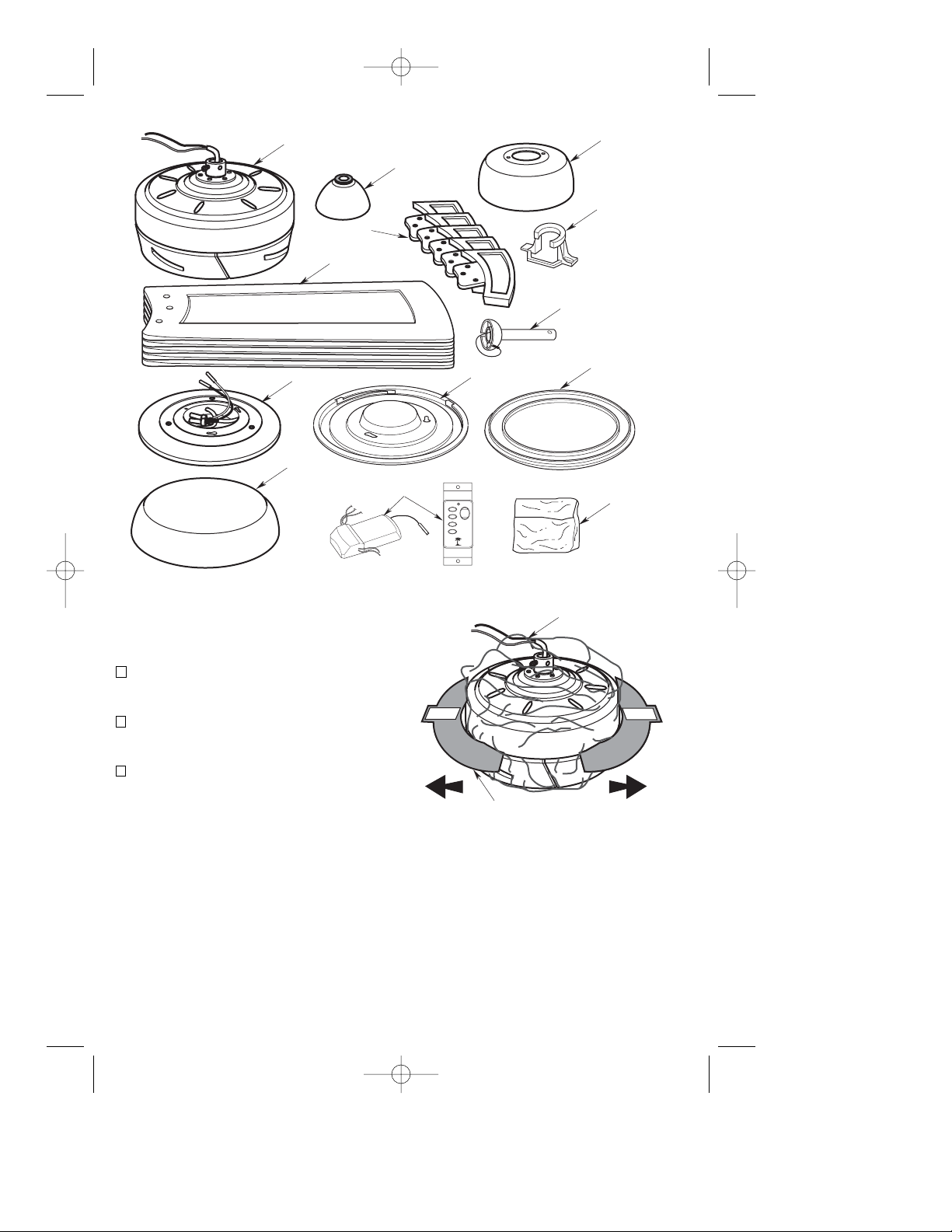
NOTE: If you are uncertain of part
description, refer to exploded view
illustration.
a. Fan motor assembly
b. One coupling cover
c. One ceiling cover
d. Five fan blades
e. Five blade flanges
f. One light kit assembly
g. One hanger bracket
h. One hanger ball/4.5” downrod assembly
i. One glass shade
j. One TBSW102 fan/light wall control
(transmitter and receiver)
k. One bottom cover (light kit omit)
l. One bottom cover adapter
m. One loose parts bag containing:
1. One clevis pin
2. One hairpin clip
3. Three 12 ga. wire connectors
4. Five wire connectors
5. Two #8-32 x 1-1/4” threaded studs
6. Two #8 external tooth lockwashers
7. Two #8-32 knurled knobs
8. Sixteen 10-32 x 1/2” oval head
flange screws
9. Sixteen 10-32 x 1/2” pan head
blade screws
10. Sixteen #10 flat washers
11. One balancing kit
1. Open carton containing fan. Remove top
half of styrofoam unit. Remove parts and
check to see that you have received the
following parts:
BP7389 Prado TB310 2/1/09 2:29 PM Page 3
4
2. Remove and discard the two cardboard
shipping retainers securing the motor hub
in the motor housing assembly.
3. Remove the fan motor assembly from the
protective plastic bag. Place all carton
contents on a protective surface.
4. Place the fan motor assembly into the lower
foam pad with the bottom of the motor
facing up. The lower foam pad serves as a
holder for the fan assembly during the next
stage of assembly.
NOTE: Place the parts from the loose
parts bags in a small container to keep
them from being lost.
BP7389 Prado TB310 2/1/09 2:29 PM Page 4
A. FAN MOTOR ASSEMBLY
E. FAN BLADE
FLANGES
D. FAN BLADES
F. LIGHT KIT ASSEMBLY
I. GLASS
J. FAN/LIGHT
WALL CONTROL
B. COUPLING
COVER
LOW
FAN OFF
L. BOTTOM COVER
ADAPTER
HI
LIGHT
MED
C. CEILING
COVER
G. HANGER
BRACKET
H. HANGER BALL/
4.5" DOWNROD
ASSEMBLY
K. BOTTOM
COVER
M. LOOSE
PARTS BAG
IMPORTANT
PROTECTIVE
PLASTIC BAG
CARDBOARD
SHIPPING RETAINER (2)
IMPORTANT
Your new ceiling fan will require a grounded
electrical supply line of 120 volts AC, 60 Hz,
15 amp circuit.
The outlet box must be securely anchored and
capable of withstanding a load of at least 50
pounds.
5
General
Your Tommy Bahama ceiling fan comes
supplied with a TBSW02 Fan/Light Wall
Control and a TBSW102 Remote
Control Receiver. The TBSW102
transmitter works in conjunction with
the receiver. The receiver is mounted
under the fan ceiling cover. The wall
control is designed to separately
control your ceiling fan speed and light
intensity.
To reduce the risk of fire, electric shock, or
personal injury, mount fan to outlet box
marked “Acceptable for Fan Support”, and
use screws supplied with outlet box. Most
outlet boxes commonly used for support of
light fixtures are not acceptable for fan
support and may need to be replaced.
Consult a qualified electrician if in doubt.
!
WARNING
If your fan is to replace an existing ceiling light
fixture, turn electricity off at the main fuse or
circuit breaker box at this time and remove the
existing light fixture.
IMPORTANT: Your ceiling fan will not
function properly, and may be damaged,
if used with any wall dimmer switch or
control other than the Tommy Bahama
TBSW102 Fan/Light Wall Control
supplied with the fan, or an optional
TBSR01 Tommy Bahama Remote
Control.
Electrical Requirements
Ceiling Fan Procedures
Turning off wall switch is not sufficient. To
avoid possible electrical shock, be sure
electricity is turned off at the main fuse or
circuit breaker box before wiring. All
wiring must be in accordance with
National and Local codes and the ceiling
fan must be properly grounded as a
precaution against possible electrical
shock.
!
WARNING
Code switches in the wall control and
receiver may be set in 16 different
positions. If your fan and light go on
and off without using your control, you
may be getting interference from other
transmitters such as garage door
openers, car alarms or security
systems. To remedy this situation,
simply change the combination code in
your wall control and receiver.
NOTE: An optional Tommy Bahama
TBSR01 Remote Control may also be
used to control your ceiling fan.
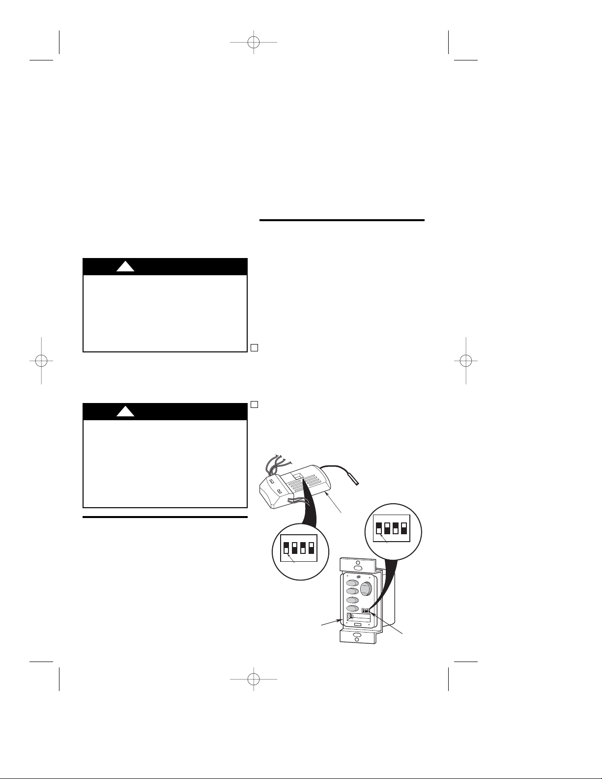
Figure 1
Setting Operating Frequency
of Wall Control and
Receiver
(Figure 1)
Your wall control and receiver have code
switches which must be set in one of 16
possible code combinations. The four levers
(numbered 1, 2, 3, and 4) on the switches are
factory-set in the ON (up) position. Change the
switch settings as follows:
1. Slide the four switch levers in the wall
control to your choice of ON (up) or down
positions. Use a ball-point pen or small
screwdriver and slide the levers firmly up or
down (Figure 1).
2. In the receiver, slide the four switch levers
to the same positions as set in the wall
control. Make sure the levers on both
switches are in the same positions,
otherwise the fan will not operate.
BP7389 Prado TB310 2/1/09 2:29 PM Page 5
ON
1
234
RECEIVER SWITCH
LEVERS
TBSW102 WALL
CONTROL
RECEIVER
FAN OFF
ON
1
234
WALL CONTROL
LEVERS
HI
HI
LIGHT
MED
MED
LOW
LOW
CODE
SWITCH
6
The TBSW102 Fan/Light Wall Control
transmits the command signals via
radio waves to the receiver installed in
the ceiling fan ceiling cover. The
receiver is required for the SW102 wall
control to function. Power for the
SW102 wall control comes from the 12V
battery, located in the wall control.
Replacement 12V battery recommended are Duracell MN21 and
Eveready A23.
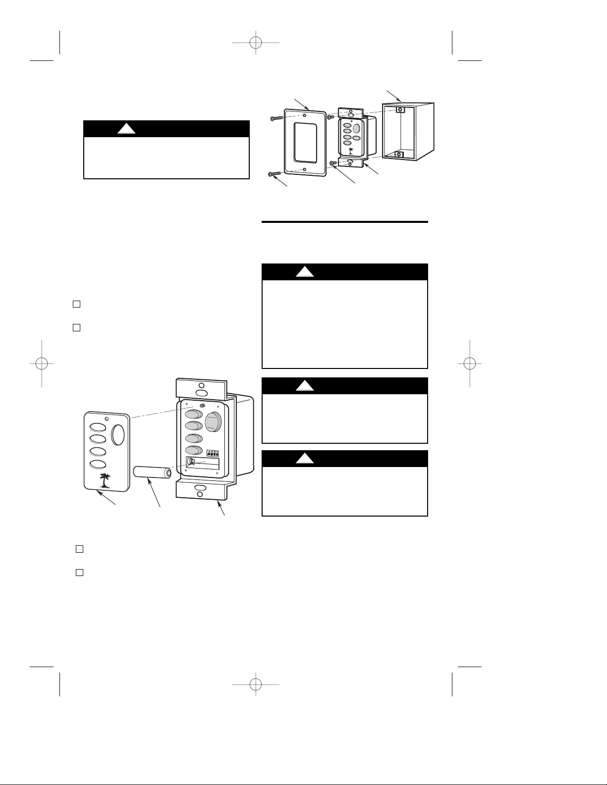
1. Install the 12V battery (supplied) into the
wall control (Figure 2).
2. The TBSW102 wall control is supplied
with a white, ivory or almond color cover.
Choose the style that best suits your needs
and snap the cover onto the wall control
(Figure 2).
3. Install the wall control onto the outlet box
using the supplied screws (Figure 3).
4. Install a decorator wall plate (purchased
separately) using the two screws provided
(Figure 3).
Battery Installation
of Wall Control
Turning off wall switch is not sufficient. To
avoid possible electrical shock, be sure
electricity is turned off at the main fuse or
circuit breaker box.
!
WARNING
Figure 2
Figure 3
How to Assemble Your
Ceiling Fan
Turning off wall switch is not sufficient. To
avoid possible electrical shock, be sure
electricity is turned off at the main fuse or
circuit breaker box before wiring. All
wiring must be in accordance with
National and Local codes and the ceiling
fan must be properly grounded as a
precaution against possible electrical
shock.
!
WARNING
To reduce the risk of personal injury, do
not bend the blade flange when installing
the blade flanges, balancing the blades or
cleaning the fan. Do not insert foreign
objects in between rotating fan blades.
!
WARNING
To To avoid possible fire or shock, follow
all wiring instructions carefully. Any
electrical work not described in these
instructions should be done or approved
by a licensed electrician.
!
WARNING
BP7389 Prado TB310 2/1/09 2:29 PM Page 6
DECORATIVE WALL PLATE
(Purchased Separately)
WALL PLATE
SCREW (2)
HI
HI
LIGHT
MED
MED
LOW
LOW
FAN OFF
OUTLET BOX
HI
LIGHT
MED
LOW
REV
FAN OFF
WALL CONTROL
SCREW (2)
TBSW102 WALL
CONTROL
WALL
CONTROL
COVER
12V BATTERY
TBSW102 WALL
CONTROL
 Loading...