

Tommy Bahama PARADISE KEY TB301MAB01 Owner's Manual
xxxxxxxxxxxxxxxxxxxxxxxxxxxxxxxxxxxxxxxxxxxxxxxxxxxxxxxxxxxxx
Net Weight:
33.5 Lbs.
Part No. F40BP72880001 Form No. BP7288-1
READ AND SAVE THESE INSTRUCTIONS
xxxxxxxxxxxxxxxxxxxxxxxxxxxxxxxxxxxxxxxxxxxxxxxxxxx
xxxxxxxxxxxxxxxxxxxxxxxxxxxxxxxxxxxxxxxxxxxxxxxxxxxxxxxxxxxxx
xxxxxxxxxxxxxxxxxxxxxxxxxxxxxxxxxxxxxxxxxxxxxxxxxxx
PARADISE KEY
Ceiling Fan
Owner's Manual
Model Number
TB301MAB01
Medium Antique Brown Housing with
Medium Antique Brown Blades
WARNING: TO REDUCE THE RISK OF FIRE, ELECTRICAL SHOCK, OR INJURY TO
PERSONS, OBSERVE THE FOLLOWING:
a. Use this unit only in a manner intended by the manufacturer. If you have questions,
contact the manufacturer.
b. Before servicing or cleaning unit, switch power off at service panel and lock service
panel disconnecting means to prevent power from being switched on accidentally.
When the service disconnecting means cannot be locked, securely fasten a warning
device, such as a tag, to the service panel.
1. Read your owner’s manual carefully and keep it for future reference.
2. Be careful of the fan and blades when cleaning, painting, or working near the fan.
Always turn off the power to the ceiling fan before servicing.
3. Do not put anything into the fan blades while they are turning.
4. Do not operate reversing switch until fan blades have come to a complete stop.
Additional Safety Instructions for Installation
1. To avoid possible shock, be sure electricity is turned off at the fuse box before wiring,
and do not operate fan without blades.
2. The installation is to be in accordance with the National Electrical Code, ANSI/NFPA
70-2011 and Local Codes. Use the National Electrical Code if Local Codes do not exist.
The ceiling fan must be grounded as a precaution against possible electrical shock.
Electrical installation should be made or approved by a licensed electrician.
3. The outlet box and joist must be securely mounted and capable of reliably supporting
at least 50 pounds. Use only U.L. outlet boxes listed as “Acceptable for Fan Support of
22.7 kg. (50 lbs.) or less”, and use the mounting screws provided with the outlet box.
Most outlet boxes commonly used for support of light fixtures are not acceptable for
fan support and may need to be replaced. Consult a qualified electrician if in doubt.
4. The fan must be mounted with the fan blades at least 7 feet from the floor to prevent
accidental contact with the fan blades.
5. Follow the recommended instructions for the proper method of wiring your ceiling
fan. If you do not know enough about electrical wiring, have your fan installed by a
licensed electrician.
NOTE: This fan is suitable for use with solid-state speed controls.
WARNING: To avoid fire, shock or injury, do not use a Tommy Bahama or any other
brand of control not specifically approved for this fan.
WARNING: This product is designed to use only those parts supplied with this product
and/or any accessories designated specifically for use with this product by Emerson
Electric Co. Substitution of parts or accessories not designated for use with this product
by Emerson Electric Co. could result in personal injury or property damage.
WARNING: To reduce the risk of personal injury, do not bend the blade flange when
installing the blade flanges, balancing the blades or cleaning the fan. Do not insert foreign
objects in between rotating fan blades.
NOTE: All setscrews must be checked and re-tightened where necessary before
installation.
!
WARNING
DATE CODE:
The date code of this fan may be found on the box, stamped in ink on a white label.
You should record this data above and keep it in a safe place for future use.
2
3
Tools Needed for Assembly
One Phillips head screwdriver
One wire stripper
One stepladder
One 5/32” hex wrench (supplied)
Six wire connectors (supplied)
Materials
Wiring, outlet box and box connectors must be
of type required by the local code. The minimum wire would be a 3-conductor (2-wire with
ground) of the following sizes:
This Manual Is Designed to Make it as Easy as Possible for You to
Assemble, Install, Operate and Maintain Your Ceiling Fan
Installed Wire Length Wire Size A.W.G.
Up to 50 ft. 14
50-100 ft. 12
Before assembling your ceiling fan, refer to
section on proper method of wiring your
fan (page 10). If you feel you do not have
enough wiring knowledge or experience,
have your fan installed by a licensed electrician.
!
WARNING
Unpacking Instructions
For your convenience, check-off boxes are provided next to each step. As each step is completed,
place a check mark in the box. This will insure that all steps have been completed and will be
helpful in finding your place should you be interrupted.
Do not install or use fan if any part is damaged or missing. Call Toll-Free:
1-800-654-3545
!
WARNING
This product is designed to use only those
parts supplied with this product and/or
any accessories designated specifically for
use with this product by Emerson Electric
Co. Substitution of parts or accessories
not designated for use with this product by
Emerson Electric Co. could result in personal injury or property damage.
!
WARNING
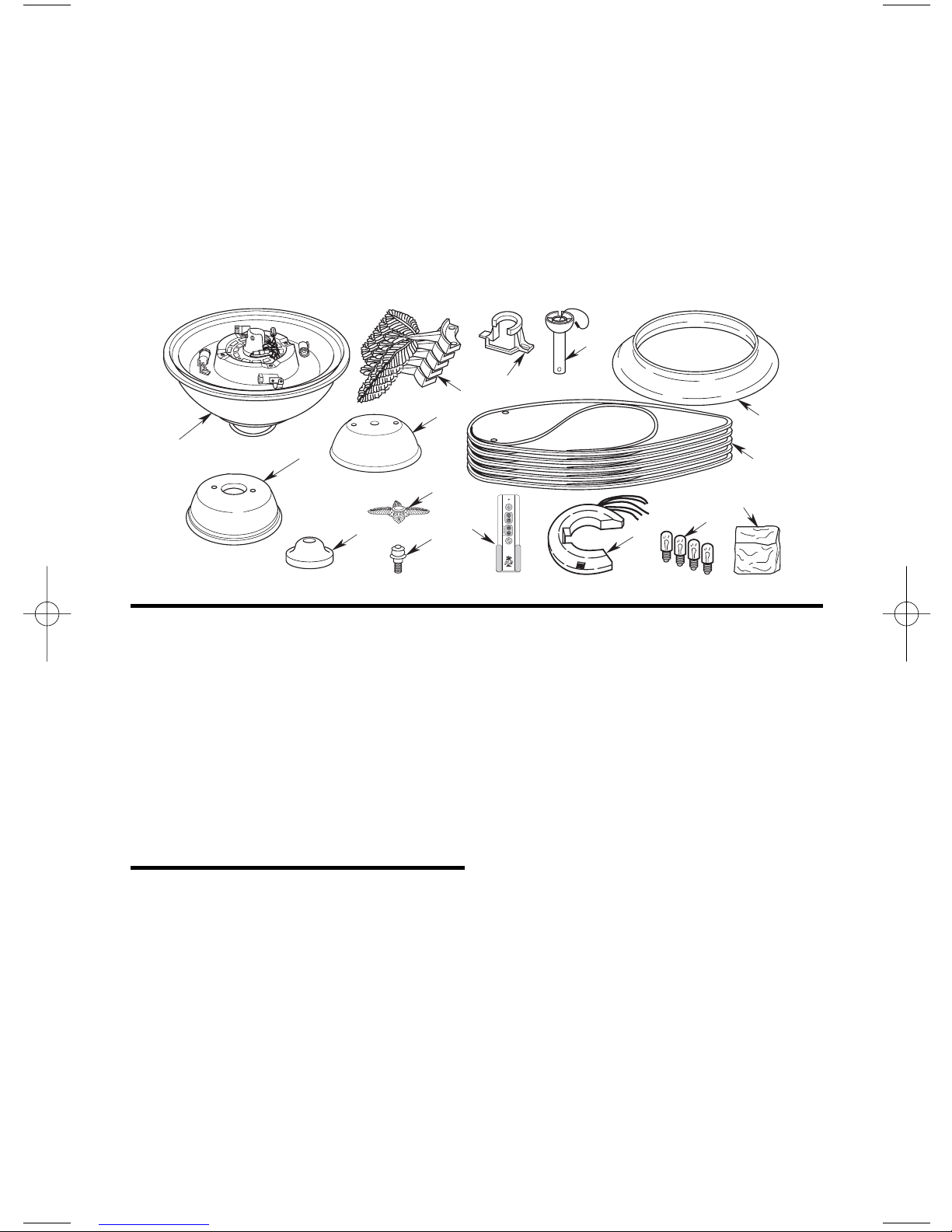
1. Open styrofoam unit containing fan.
Remove top half of styrofoam unit.
Remove parts and check to see that you
have received the following parts:
NOTE: If you are uncertain of part
description, refer to exploded view illustration.
a. Fan motor and housing assembly
b. One ceiling cover
c. One motor cover
d. Five blade flanges
e. One hanger bracket
f. One hanger ball/downrod assembly
g. One switch housing cover
h. One housing cover trim
i. One finial nut
j. One upper glass
k. Five fan blades
l. One TBSR600 remote control transmitter
m. One RCK55 remote control receiver
n. Four 25-watt candelabra base bulbs
4
o. One loose parts bag containing:
1. One 5/16-18 x 1/4” setscrew
2. One 5/32” hex wrench
3. Two 1” threaded studs
4. Two 1-1/4” threaded studs
5. Four knurled knobs
6. Four lockwashers
7. Six wire connectors
8. One clevis pin/hairpin clip
assembly
9. Eleven 10-32 x 5/8” oval head
screws
10. Sixteen 10-32 x 3/8”
Phillips pan head screws
11. Sixteen #10 flat washers
12. Two 8-32 x 14mm pan
head screws
NOTE: Place the parts from the loose
parts bags in a small container to keep
them from being lost. If any parts are
missing, contact your local retailer or
catalog outlet for replacement before
proceeding.
General
Your Tommy Bahama ceiling fan comes
equipped with a remote control transmitter
and a remote control receiver. This remote
control systems is designed to control your ceiling fan speed, airflow direction, and light
intensity.
NOTE: An optional SR650 or SW605 Wall
Control (not supplied) may also be used
with the remote control receiver supplied with your ceiling fan.
IMPORTANT
This Owner’s Manual is divided into two
sections. The first section, REMOTE
CONTROL PROCEDURES, describes
how to install the four alkaline batteries
(not supplied) in the remote control
transmitter, and how to set the operating frequency of the transmitter and
receiver. These instructions must be
performed prior to the installation of
the ceiling fan as described in the second
section, CEILING FAN PROCEDURES.
Remote Control Procedures
General
Your Tommy Bahama Ceiling Fan/Light
Remote Control consists of hand-held transmitter and a receiver which is mounted under
the fan ceiling cover. The remote control is
designed to separately control your ceiling fan
speed and light intensity.
The remote control transmitter is powered by
two AAA alkaline batteries (not included). To
prevent possible damage if the batteries should
leak, be sure to remove the batteries when the
control is not to be used for an extended period of time.
Code switches in the transmitter may be set in
32 different positions. If your fan and light go
on and off without using your control, you
may be getting interference from other remote
units such as garage door openers, car alarms
or security systems. To remedy this situations,
simply change the combination code in your
transmitter.
A
F
E
D
G
B
H
C
L
I
M
N
J
K
O
Preset Memory Feature
Your Tommy Bahama receiver is equipped
with a preset memory feature. If the AC supply to the receiver is powered through a wall
switch, when the switch is turned OFF, the
control will remember the light intensity and
fan speed. When the switch is turned back ON
the light and fan will resume operation as they
were prior to the switch being turned OFF.
5
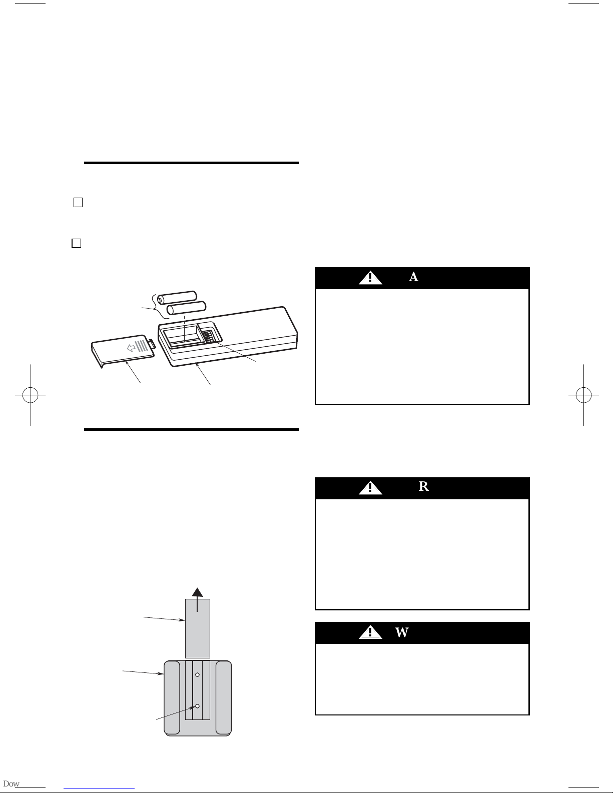
Installation of Battery
Figure 1
1. Remove the battery cover by pressing firm-
ly below the arrow and sliding the cover off
the control (Figure 1).
2. Remove the connector from the battery
compartment and install two AAA alkaline
batteries.
Installation of Storage
Bracket
A storage bracket is provided for holding your
remote control when not in use. If you desire
to use the bracket, install it on a wall that is
away from excess heat or humidity (Figure 2).
Figure 2
IMPORTANT: Your ceiling fan will not
function properly, and may be damaged,
if used with any wall dimmer switch or
control other than the Tommy Bahama
TBSR600 Fan/Light Remote Control
supplied with the fan.
CEILING FAN PROCEDURES
Electrical Requirements
To avoid possible fire or shock, follow all
wiring instructions carefully.
Any electrical work not described in these
instructions should be done or approved
by a licensed electrician.
!
WARNING
To reduce the risk of fire, electric shock, or
personal injury, mount fan to outlet box
marked “Acceptable for Fan Support of
22.7 kg. (50 lbs.) or less”, and use screws
supplied with outlet box. Most outlet boxes
commonly used for support of light fixtures are not acceptable for fan support
and may need to be replaced. Consult a
qualified electrician if in doubt.
!
WARNING
If your fan is to replace an existing ceiling light
fixture, turn electricity off at the main fuse or
circuit breaker box at this time and remove the
existing light fixture.
Turning off wall switch is not sufficient. To
avoid possible electrical shock, be sure
electricity is turned off at the main fuse or
circuit breaker box before wiring. All
wiring must be in accordance with
National and Local codes and the ceiling
fan must be properly grounded as a precaution against possible electrical shock.
!
WARNING
Your new ceiling fan will require a grounded
electrical supply line of 120 volts AC, 60 Hz,
15 amp circuit.
The outlet box must be securely anchored and
capable of withstanding a load of at least 50
pounds.
TWO AAA
BATTERIES
BATTERY
COMPARTMENT
COVER
TBSR600 REMOTE
CONTROL
TO INSTALL BRACKET TO WALL:
SLIDE THE COVER UP TO EXPOSE THE SCREW
HOLES FOR INSTALLATION
CODE
SWITCHES
COVER
WALL
BRACKET
SCREW
HOLES (2)
6
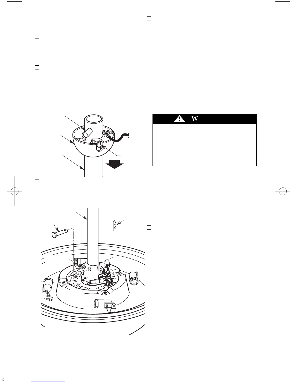
!
WARNING
It is critical that the clevis pin in the motor
coupling is properly installed and the
setscrew securely tightened. Failure to verify that the pin and setscrew are properly
installed (as shown in Figure 4) could result
in the fan falling.
1. Remove the fan motor and housing assem-
bly from the styrofoam packaging and position it so that the top of the motor is facing
you.
2. Remove the hanger ball from the downrod
by loosening the set-screw in the hanger
ball until the ball falls freely down the
downrod (Figure 3). Remove the pin from
the downrod, then remove the hanger ball.
Retain the pin and hanger ball for reinstallation in step 8.
3. Separate, untwist and unkink the four
motor leads. Route the motor leads through
the downrod and seat the downrod in the
motor coupling (Figure 4).
Figure 3
Figure 4
How to Assemble Your
Ceiling Fan
4. Align the clevis pin holes in the downrod
with the holes in the motor coupling. Install
the clevis pin and secure with the hairpin
clip (Figure 4). (Pin and clip are supplied in
loose parts bag.) The clevis pin must go
through the holes in the motor coupling
and the holes in the downrod. Push the
straight leg of the hairpin clip through the
hole near the end of the clevis pin until the
curved portion of the hairpin clip snaps
around the clevis pin. The hairpin clip must
be properly installed to prevent the clevis
pin from working loose. Pull on the downrod to make sure the clevis pin is properly
installed.
5. Install the 5/16-18 x 1/4” setscrew
(supplied) in the motor coupling (Figure 5).
While pulling up on the downrod, tighten
the setscrew using the 5/32” hex wrench
(supplied).
NOTE: The setscrew must be properly
installed as described above, or fan wobble could result.
6. Screw two 1” threaded studs (supplied) into
the motor (Figure 5). Leave approximately
7/8” of the stud extending above the
motor. Coil the wires and wire connectors
around the motor coupling then slide the
motor cover over the downrod and rotate
the cover until the threaded studs protrude.
Install two lockwashers and knurled knobs
(supplied) to secure the cover to the motor.
All wires and wire connectors must be
enclosed under the motor cover.
PIN
HANGER
BALL
DOWNROD
SETSCREW
DOWNROD
CLEVIS
PIN
SETSCREW
MOTOR
COUPLING
HAIRPIN
CLIP
 Loading...