

Tommy Bahama CABRILLO COVE Instructions Manual
Part No. F40BP74650000 Form No. BP7465
Revision - 130422 Model No.: TB135
IMPORTANT, RETAIN FOR FUTURE REFERENCE:
READ CAREFULLY
Tommy Bahama
INDOOR/OUTDOOR
52 in. / 132 cm.
CABRILLO COVE
CEILING FAN
Net Weight:
31.0 lb. / 14.1 kg.
Cabrillo Cove Ceiling Fan with
Tropical Blades
Cabrillo Cove Ceiling Fan with
Paddle Blades
ITM./ART. 702146
Questions, problems, missing parts? Before returning to the store call Emerson Customer Service
8 a.m. - 8 p.m., CST, Monday - Friday
8 a.m. - 5 p.m., CST, Saturday - Sunday
1-800-875-3545
Email Help - email@carrollparts.com
Installation - 2 people
recommended, could
take up to several hours
Tommy Bahama • 04/2013 email@carrollparts.com • 1-800-875-3545
2
Safety Warning. . . . . . . . . . . . . . . . . . . . . . . . . . . . . . . . . . . . . . . . . . . . . . . . . . . . . . . . . . . . . . . . . . . 3
1. Preparation . . . . . . . . . . . . . . . . . . . . . . . . . . . . . . . . . . . . . . . . . . . . . . . . . . . . . . . . . . . . . . . . . . 4
2. Ceiling Fan Location . . . . . . . . . . . . . . . . . . . . . . . . . . . . . . . . . . . . . . . . . . . . . . . . . . . . . . . . . . 5
3. Electrical Requirements . . . . . . . . . . . . . . . . . . . . . . . . . . . . . . . . . . . . . . . . . . . . . . . . . . . . . . . . 6
4. How to Assemble Your Ceiling Fan . . . . . . . . . . . . . . . . . . . . . . . . . . . . . . . . . . . . . . . . . . . 7-12
5. How to Remove the Light Kit from the Fan . . . . . . . . . . . . . . . . . . . . . . . . . . . . . . . . . . . . 13-15
6. How to Assemble Your Light Kit . . . . . . . . . . . . . . . . . . . . . . . . . . . . . . . . . . . . . . . . . . . . 16-17
7. How to Hang Your Ceiling Fan . . . . . . . . . . . . . . . . . . . . . . . . . . . . . . . . . . . . . . . . . . . . . . 18-19
8. How to Wire Your Ceiling Fan . . . . . . . . . . . . . . . . . . . . . . . . . . . . . . . . . . . . . . . . . . . . . . . 20-24
9. Installation of the Ceiling Cover. . . . . . . . . . . . . . . . . . . . . . . . . . . . . . . . . . . . . . . . . . . . . . . . . . 25-26
10. Installation of Glass Shade . . . . . . . . . . . . . . . . . . . . . . . . . . . . . . . . . . . . . . . . . . . . . . . . . . . . . . 27-28
11. Transmitter Battery Installation and Code Setting . . . . . . . . . . . . . . . . . . . . . . . . . . . . . . . 29-31
12. Receiver Code Leaning - Programming the Operating Frequency of the Receiver. . . . . . . 32
13. Operation of Remote Control . . . . . . . . . . . . . . . . . . . . . . . . . . . . . . . . . . . . . . . . . . . . . . . . . . 33
14. Installation of the Storage Bracket . . . . . . . . . . . . . . . . . . . . . . . . . . . . . . . . . . . . . . . . . . . . . . 34
15. Using Your Ceiling Fan . . . . . . . . . . . . . . . . . . . . . . . . . . . . . . . . . . . . . . . . . . . . . . . . . . . . . . . . . 35-36
16. Interchanging Fan Blades on Installed Fan . . . . . . . . . . . . . . . . . . . . . . . . . . . . . . . . . . . . 37-38
17. Trouble Shooting. . . . . . . . . . . . . . . . . . . . . . . . . . . . . . . . . . . . . . . . . . . . . . . . . . . . . . . . . . . . . 39
18. Remote Control Trouble Shooting. . . . . . . . . . . . . . . . . . . . . . . . . . . . . . . . . . . . . . . . . . . . . . . 40
19. Maintenance . . . . . . . . . . . . . . . . . . . . . . . . . . . . . . . . . . . . . . . . . . . . . . . . . . . . . . . . . . . . . . . . 41
20. Digital Device Warning. . . . . . . . . . . . . . . . . . . . . . . . . . . . . . . . . . . . . . . . . . . . . . . . . . . . . . . . 41
21. Repair Parts . . . . . . . . . . . . . . . . . . . . . . . . . . . . . . . . . . . . . . . . . . . . . . . . . . . . . . . . . . . . . 42-43
Warranty . . . . . . . . . . . . . . . . . . . . . . . . . . . . . . . . . . . . . . . . . . . . . . . . . . . . . . . . . . . . . . . . . . . . . . 44
Table of Contents
WARNING: TO REDUCE THE RISK OF FIRE, ELECTRICAL SHOCK, OR INJURY TO PERSONS,
OBSERVE THE FOLLOWING:
a. Use this unit only in a manner intended by the manufacturer. If you have questions, contact the manufacturer,
1-800-875-3545.
b. Before servicing or cleaning unit, switch power off at service panel and lock service panel disconnecting means to
prevent power from being switched on accidentally. When the service disconnecting means cannot be locked,
securely fasten a warning device, such as a tag, to the service panel.
1. Read your owner’s manual carefully and keep it for future reference.
2. Be careful of the fan and blades when cleaning, painting, or working near the fan. Always turn off the power to the
ceiling fan before servicing.
3. Do not put anything into the fan blades while they are turning.
4. Do not operate reversing switch until fan blades have come to a complete stop.
Additional Safety Instructions for Installation
1. To avoid possible shock, be sure electricity is turned off at the fuse box before wiring, and do not operate fan
without blades.
2. The installation is to be in accordance with the National Electrical Code, ANSI/NFPA 70-2011 and Local Codes.
Use the National Electrical Code if Local Codes do not exist. The ceiling fan must be grounded as a precaution
against possible electrical shock. Electrical installation should be made or approved by a licensed electrician.
3. The outlet box and joist must be securely mounted and capable of reliably supporting at least 50 lb. / 23 kg. Use
only U.L. outlet boxes listed as “Acceptable for Fan Support of 35 lb. / 16 kg. or less”, and use the mounting screws
provided with the outlet box. Most outlet boxes commonly used for support of light fixtures are not acceptable for
fan support and may need to be replaced. Consult a qualified electrician if in doubt.
4. The fan must be mounted with the fan blades at least 7 ft. / 2.1 m. from the floor to prevent accidental contact with
the fan blades.
5. Follow the recommended instructions for the proper method of wiring your ceiling fan. If you do not know enough
about electrical wiring, have your fan installed by a licensed electrician.
WARNING: To reduce the risk of electrical shock, this fan must be installed with an isolating wall
control/switch. A standard wall switch meets this requirement.
WARNING: To reduce the risk of fire or electric shock, do not use this fan with any solid-state speed control
device. Solid-state speed controls cannot meet the requirements of wet location usage, consult Emerson
customer service, 1-800-875-3545 for further assistance.
NOTE: If replacing the original supplied light kit, use only light kits marked “Suitable for use in wet locations”.
CAUTION: To reduce the risk of electric shock, disconnect the electrical supply circuit to the fan before
installing light kit.
WARNING: To avoid fire or electric shock, this fan should only be used with fan speed control Model No.
UC7067RYA, manufactured by Rhine Electric Co., Ltd.
WARNING: This product is designed to use only those parts supplied with this product and/or any accessories
designated specifically for use with this product by Emerson Electric Co. Substitution of parts or
accessories not designated for use with this product by Emerson Electric Co. could result in personal injury
or property damage.
WARNING: To reduce the risk of personal injury, do not bend the blade holders when installing the blade
holder assemblies, balancing the blades or cleaning the fan. Do not insert foreign objects in between rotating fan
blades.
NOTE: All setscrews must be checked and re-tightened where necessary before installation (See Section 4).
NOTE: Suitable for use in wet locations when installed in a GFCI protected branch circuit.
3
!
WARNING
DATE CODE:
The date code of this fan may be found on the box, stamped in ink on a white label.
You should record this data above and keep it in a safe place for future use.
READ AND SAVE THESE INSTRUCTIONS
Tommy Bahama • 04/2013 email@carrollparts.com • 1-800-875-3545
4
Tommy Bahama • 04/2013 email@carrollparts.com • 1-800-875-3545
Thank You for Your Purchase
Your Tommy Bahama Ceiling Fan is the right choice for
your home or office. We take pride in providing you with
an efficient, reliable and excellent craftsmanship product
for years to come.
Unpacking Instructions
Optional Accessories
Open the fan carton and carefully remove all the
components packed inside the upper and lower styrofoam
pads. Place all parts on a soft surface to prevent scratching
the painted finish. Please set aside the styrofoam pads as
these will be used later during assembly.
Refer to the separate Parts/Hardware Guide and check that
you have received all hardware and ceiling fan
components. Call Emerson Customer Service at
1-800-875-3545 if any hardware or components are
missing from the carton. New parts will be shipped free of
charge.
Tommy Bahama has optional accessories, including wall
controls or remote control devices for your ceiling fan.
1. To order Remote Wall Control TBSW102, go to:
www.emersonacp.com/FansStore/home.do.
2. To order an additional Handheld transmitter TBSR135,
go to: www.emersonacp.com/FansStore/home.do.
Use of This Manual
Read the entire manual before installation. This manual
will help you install, operate and maintain your ceiling fan.
These instructions are designed to make installation and
assembly as simple and efficient as possible. Each step has
three components:
1. Each step has a number for ease of step by step
instructions.
2. Text instructions above each illustration describes the
procedure for each step.
3. Each assembly illustration is marked with component
identification number that corresponds to the Hardware
Guide included with this ceiling fan.. Lower case letters
refer to components removed from pre-assembled parts.
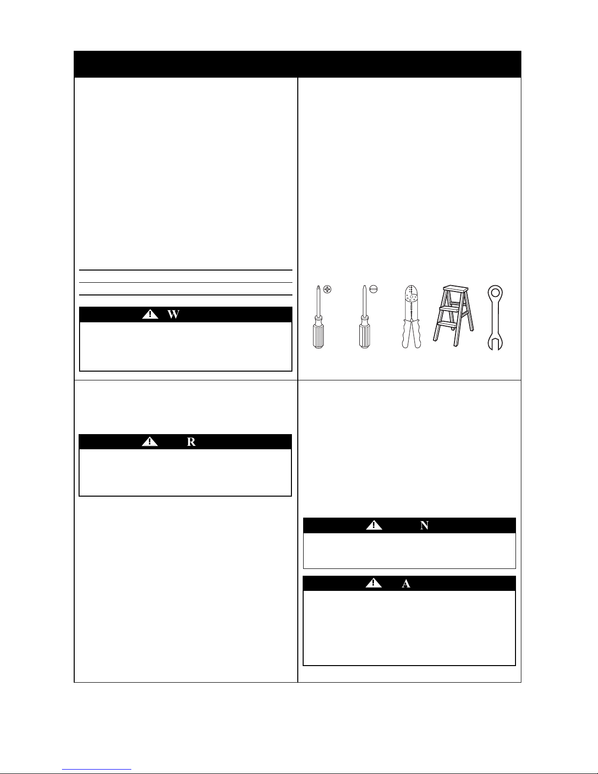
Tools Required
Before Installation
This fan is suitable for wet locations such as
porches, patios, and decks.
Wiring, outlet box and box connectors must be of type
required by the local code. The minimum wire would be a
3-conductor (2-wire with ground) of the following sizes:
Installed Wire Length Wire Size A.W.G.
Up to 50 ft. / 15.2 m. 14
50-100 ft. / 15.2-30.4 m. 12
1. Preparation
Before assembling your ceiling fan, refer to section on
proper method of wiring your fan. If you feel you do
not have enough wiring knowledge or experience,
have your fan installed by a licensed electrician.
!
WARNING
This product is designed to use only those parts
supplied with this product and/or any accessories
designated specifically for use with this product by
Emerson Electric Co. Substitution of parts or
accessories not designated for use with this product
by Emerson Electric Co. could result in personal
injury or property damage.
!
WARNING
Phillips
Screwdriver
Wire
Stripper
Step
Ladder
Do not install or use fan if any part is damaged or
missing. For free replacement parts Call Toll-Free:
1-800-875-3545
!
WARNING
The use of any other control not specifically approved
for this fan could result in fire, shock and personal
injury.
!
WARNING
Small Flat Blade
Screwdriver
14 mm Box
Wrench
1.1 1.2
1.3 1.4
5
Tommy Bahama • 04/2013 email@carrollparts.com • 1-800-875-3545
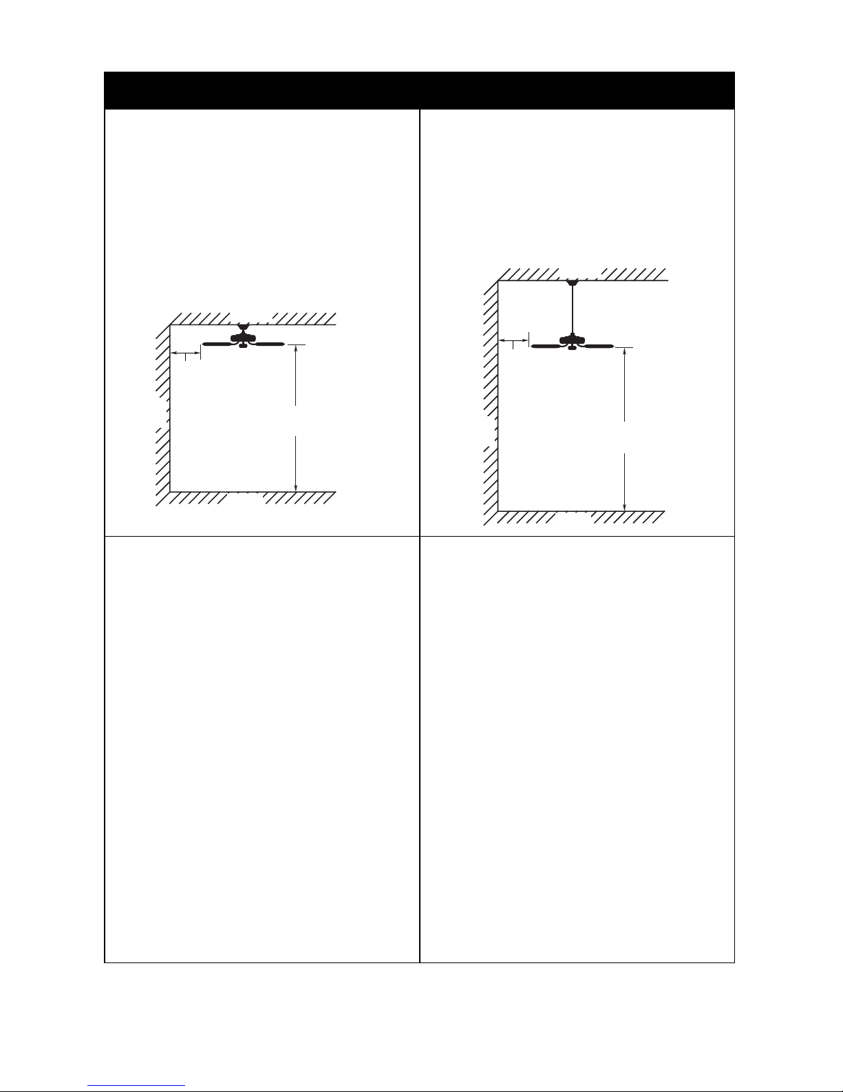
Standard 8 Ft. / 2.4 m. Ceilings
Use the Supplied 4.5 in. /11.4 cm. Downrod
For Installation
Your Tommy Bahama Ceiling Fan is designed for flat,
standard 8 ft. / 2.4 m. ceilings, even when a light kit is
utilized. When installed, the blades should be at least 7 ft. /
2.1 m. from the floor. Contact Emerson Customer Service
at 1-800-875-3545 if you have a sloped ceiling.
2. Ceiling Fan Location
Ceilings 9 F.t / 2.7 m. and Higher
Use the Supplied 18 in. / 45.7 cm. Downrod
For Installation
On flat high ceilings, use the 18 in. / 45.7 cm. downrod
(supplied) to achieve the optimum installation height.
Choose the Ceiling Fan Location
Proper ceiling fan location and attachment to the building
structure are essential for safety, reliable operation,
maximum efficiency, and energy savings
• No object can come into contact with the rotating fan
blades during normal operation
• The fan blades are at lease 7 ft. / 2.1 m. above the floor
and the ceiling is at lease 8 ft. / 2.4 m. high.
• The fan blades have no obstructions to airflow, such as
walls, or posts, within 30 in. / 76.2 cm. of the fan blade
tips.
• Always use a ceiling outlet box marked with at least a
minimum of "Acceptable for Fan Support of 35 lb. /
15.9 kg. or less" to hang your fan from. 50 lb. /
22.7 kg. and 75 lb. / 34.0 kg. rated outlet boxes are also
acceptable.
• If your ceiling outlet box is not marked as described
above, have a licensed electrician install the required
outlet box.
• The outlet box must be mounted to a flat ceiling in order
to accommodate the remote control receiver.
Call Emerson Electric at 1-800-875-3545 to discuss
optional control methods, and sloped ceiling installation.
Existing Ceiling Fan or Light Fixture
Installation Checklist
If you want to use an existing fan/fixture site, complete the
following checklist to determine if the site is acceptable
and safe for your new Tommy Bahama ceiling fan.
Fan Support System:
• The building structure is capable of supporting at least
50 lb. / 22.7 kg.
Outlet Box:
• The outlet box is UL approved and marked with a
minimum weight rating of " Acceptable for Fan Support
of 35 lb. / 15.9 kg. or less".
• The bottom of the outlet box is recessed a minimum of
0.1 in. / 0.3 cm. into ceiling.
Wiring:
• 6 in. / 15.2 cm. of lead wires extend from outlet box.
If your existing fan site is suitable, continue to “How to
Assemble Your Ceiling Fan”.
2.1 2.2
2.3 2.4
MIN. 30 in. /
76.2 cm.
MIN. 8 ft. /
2.4 m.
MIN. 30 in. /
76.2 cm.
MIN. 7 ft. /
2.1 m.
Your Tommy Bahama TB135 ceiling fan is rated for
installation in a wet location, it can also be installed
indoors.
18"
MIN.
WALL
CEILING
FLOOR
7'
MIN.
18"
MIN.
WALL
CEILING
FLOOR
8' TO
10'
3. Electrical Requirements
If your new fan is to replace an existing fan or light fixture,
turn electricity off at the main fuse or circuit box at this
time and remove the existing light fixture.
Turning off wall switch is not sufficient. To avoid
possible electrical shock, be sure electricity is turned
off at the main fuse or circuit breaker box before
wiring. All wiring must be in accordance with
National and Local codes and the ceiling fan must be
properly grounded as a precaution against possible
electrical shock.
!
WARNING
To avoid possible fire or shock, follow all wiring
instructions carefully.
Any electrical work not described in these
instructions should be done or approved by a licensed
electrician.
!
WARNING
Your new ceiling fan will require a grounded electrical
supply of 120 volts AC, 60 Hz, 15 amp circuit.
The outlet box must be securely anchored and capable of
withstanding a load of at least 50 lb. / 23 kg.
6
Tommy Bahama • 04/2013 email@carrollparts.com • 1-800-875-3545
IMPORTANT
Your ceiling fan and remote control will not function
properly and may be damaged if used with any other
remote control other than a Tommy Bahama remote
control. Use only the Tommy Bahama remote control and a
listed general use on/off wall switch.
3.1 3.2
MAIN FUSE BOX OR
CIRCUIT BREAKER
BOX
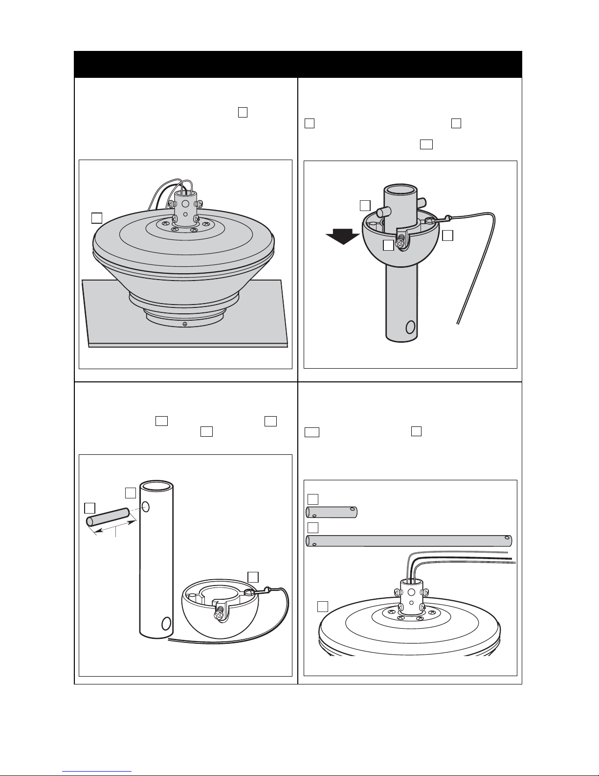
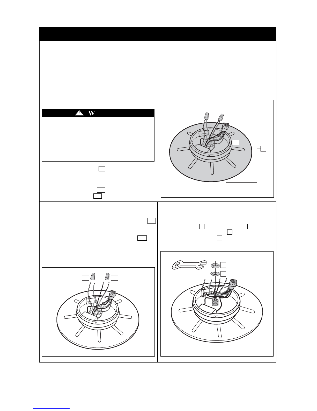
4. How to Assemble Your Ceiling Fan
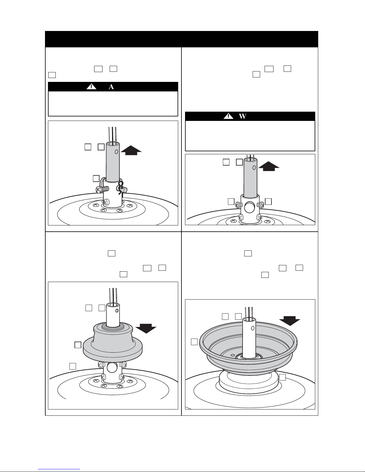
Locate the 4.5 in. (11.4 cm) downrod hanger ball assembly
2 and loosen the hanger ball setscrew a with a phillips
screw driver until the ball is free to slide down the
downrod. Retain the hanger ball 2a for future use.
7
Tommy Bahama • 04/2013 email@carrollparts.com • 1-800-875-3545
4.1 4.2
Position the fan motor housing assembly 4 onto a soft
padded work surface to prevent scratching the fan. Position
the fan so that the top of the motor is facing up.
Your ceiling fan is supplied with a 4.5 in. / 11.4 cm.
2b and 18 in. / 45.7 cm. 3 long downrods. Use the
shorter downrod if your ceiling height is less than 9 ft. /
2.7 m. The 18 in. / 45.7 cm. downrod is usable only when
your ceiling height is 9 ft. / 2.7 m. or higher.
4.3 4.4
With the hanger ball 2a removed, the retainer pin 2c can
be removed from the downrod 2b . Retain the pin for
future use.
4
2
2a
a
2c
1.4 in. x 0.3 in. /
3.5 cm. x 0.6 cm.
2b
2a
2b
3
4
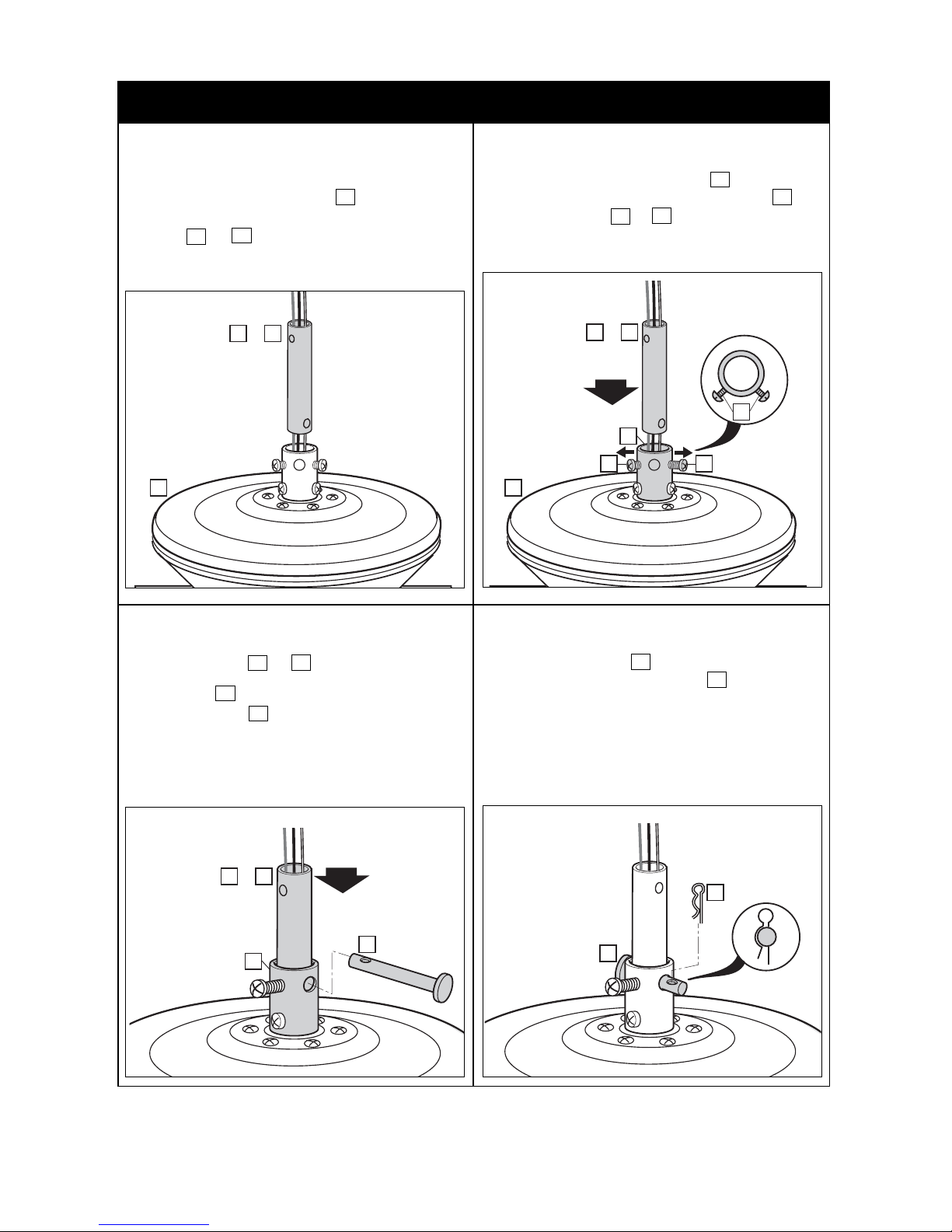
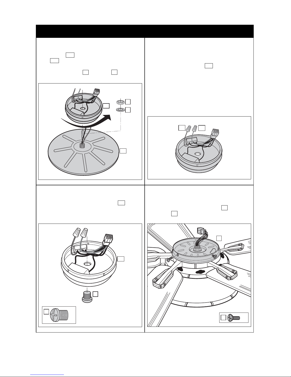
4. How to Assemble Your Ceiling Fan (Continued)
Locate the hairpin clip 23 from the hardware kit and
install it into the tip of the clevis pin 24 by pushing the
straight leg of the clip through the hole at the tip of the pin.
The curved leg of the hairpin clip must snap around the
outside of the pin for correct installation.
The hairpin clip must be properly installed to prevent the
clevis pin from working loose.
8
Tommy Bahama • 04/2013 email@carrollparts.com • 1-800-875-3545
4.7 4.8
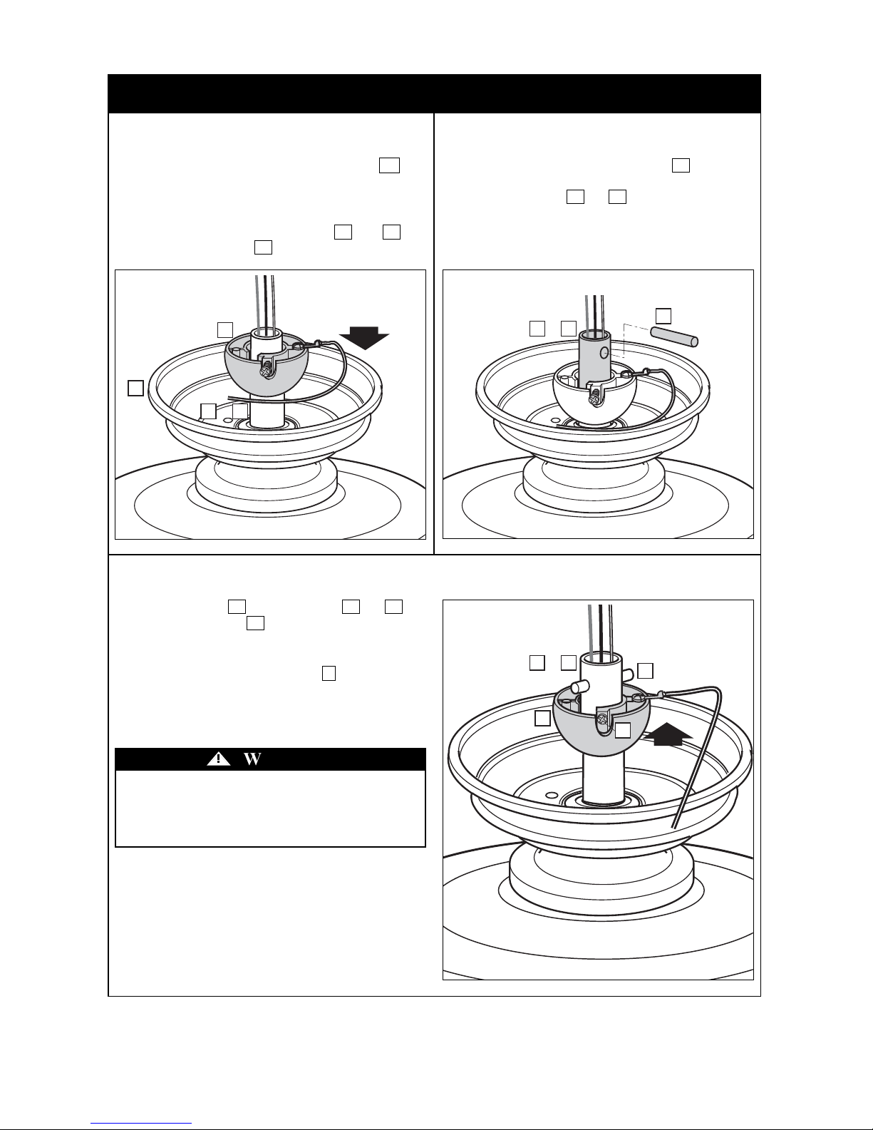
Rotate the downrod 2b or 3 until its bottom mounting
holes are aligned with the mating mounting holes of the
motor coupling e .
Locate the clevis pin 24 from the hardware pack and push
it into the aligned mounting holes.
The motor wires may cause some interference and it may
take several attempts to push the pin through both side of
the downrod.
Loosen two motor coupling setscrews d so that they do
not protrude into the interior of the motor coupling e .
Position the downrod 2b or 3 above the motor coupling
and carefully slip it into the coupling until it is fully
inserted.
4.5 4.6
Separate, untwist and unkink the three coiled motor wires
protruding from the top of the motor 4 .
Route all three motor wires into the end of the selected
downrod 2b or 3 and push until they appear at the
opposite end. Grasp the end of the wires and pull the
remaining wire through the downrod.
4
2b or 3
2b or 3
d
e
dd
4
2b or 3
24
e
23
24
4. How to Assemble Your Ceiling Fan (Continued)
Locate the ceiling cover 5 and route the motor wires
through the center hole.
Slide the ceiling cover down the downrod 2b or 3 until
it rests on top of the coupler cover 6 .
Be sure the ceiling cover is oriented correctly, with the
large opening facing upward.
9
Tommy Bahama • 04/2013 email@carrollparts.com • 1-800-875-3545
4.11 4.12
Locate the coupler cover 6 and route the motor wires
through the center hole.
Slide the coupler cover down the downrod 2b or 3 until
it rests on the fan motor housing 4 .
While pulling up on the downrod 2b or 3 , securely
tighten the two setscrews d that were previously
loosened using a phillips screwdriver. Tighten both screws
evenly to ensure the downrod remains vertically straight
inside the motor coupling.
NOTE: The setscrews must be properly installed as
described above, or fan wobble could result.
4.9 4.10
Pull on the downrod 2b or 3 to make sure the clevis pin
24 is properly installed.
It is critical that the setscrews are securely tightened
in the motor coupling. Failure to verify that the
setscrews are properly installed could result in the
fan falling.
!
WARNING
It is critical that the clevis pin in the motor coupling
is properly installed. Failure to verify that the clevis
pin is properly installed could result in the fan falling.
!
WARNING
2b or 3
24
2b or 3
dd
2b or 3
6
4
2b or 3
5
6
4. How to Assemble Your Ceiling Fan (Continued)
10
Tommy Bahama • 04/2013 email@carrollparts.com • 1-800-875-3545
4.15
Slide the hanger ball 2a up the downrod 2b or 3 and
engage the retainer pin 2c in the groove on top of the
hanger ball.
Keep the ball engaged with the retainer pin with one hand
and tighten the hanger ball setscrew a with a phillips
screw driver using the other hand. Pull up on the hanger
ball when tightening the setscrew.
A loose setscrew could create fan wobble.
Locate the previously removed retainer pin 2c previously
removed from the downrod and insert it into the holes at
the top of the downrod 2b or 3 . The motor wires may
cause some interference and it may take several attempts to
push the pin through both sides of the downrod.
4.13 4.14
Locate the previously removed hanger ball 2a and
reinstall it onto the downrod by routing the motor wires
through the center hole. Be sure the ball is oriented with
the flat surface facing up.
Slide the hanger ball onto the downrod 2b or 3 and
rest it on the ceiling cover 5 .
It is critical that the pin in the hanger ball is properly
installed and the setscrew securely tightened. Failure
to verify that the pin and setscrew are properly
installed could result in the fan falling.
!
WARNING
2a
5
2b or 3
2b or 3
2c
2b or 3
2a
2c
a
4. How to Assemble Your Ceiling Fan (Continued)
11
Tommy Bahama • 04/2013 email@carrollparts.com • 1-800-875-3545
4.17
NOTE: Your fan is supplied with two complete blade
sets. At this time, choose which blade set you want for
your decor and proceed as instructed below. These
blades are a weight-matched set. Assemble five blades
from one set. DO NOT MIX THEM WITH BLADES
FROM ANOTHER SET. mixing blade sets can cause
your fan to wobble.
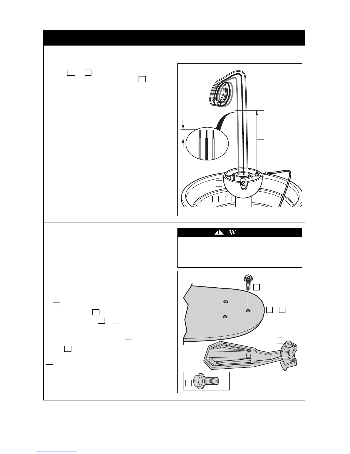
Locate the following items:
1. Fifteen #10-24 x 0.4 in. / 1.0 cm. flange head screws
18 from the the hardware kit.
2. Five blade holders 9 .
3. One set of fan blades 7 or 8 of your choice.
Place a blade holder on the decorative bottom surface of the
blade as shown. The blade holder 9 has three raised
bosses that must drop into the mating holes on the blade
7 or 8 . Attach the blade holder to the blade using
three of the #10-24 x 0.4 in. / 1.0 cm. flange head screws
18 using a phillips screwdriver. Securely tighten the
screws.
NOTE: Be sure the plain side of the ceiling fan blade is
facing up.
Repeat this procedure for the remaining four blades.
4.16
Grasp the motor wires and pull them straight up above the
downrod 2b or 3 . Cut all three wires 6 in. to 9 in. /
15.2 cm. to 22.9 cm. above the hanger ball 2a using wire
cutters.
Strip back the wire insulation 0.5 in. / 1.3 cm. from the end
of each wire using wire stripers.
To reduce the risk of personal injury, do not bend the
blade holders when installing the holders, balancing
the blades, or cleaning the fan. Do not insert foreign
objects between rotating fan blades.
!
WARNING
0.5 in. /
1.3 cm.
6 in. / 15.2 cm. to
9 in. / 22.9 cm.
2a
2b or 3
18
x 16
18
7or8
9
4. How to Assemble Your Ceiling Fan (Continued)
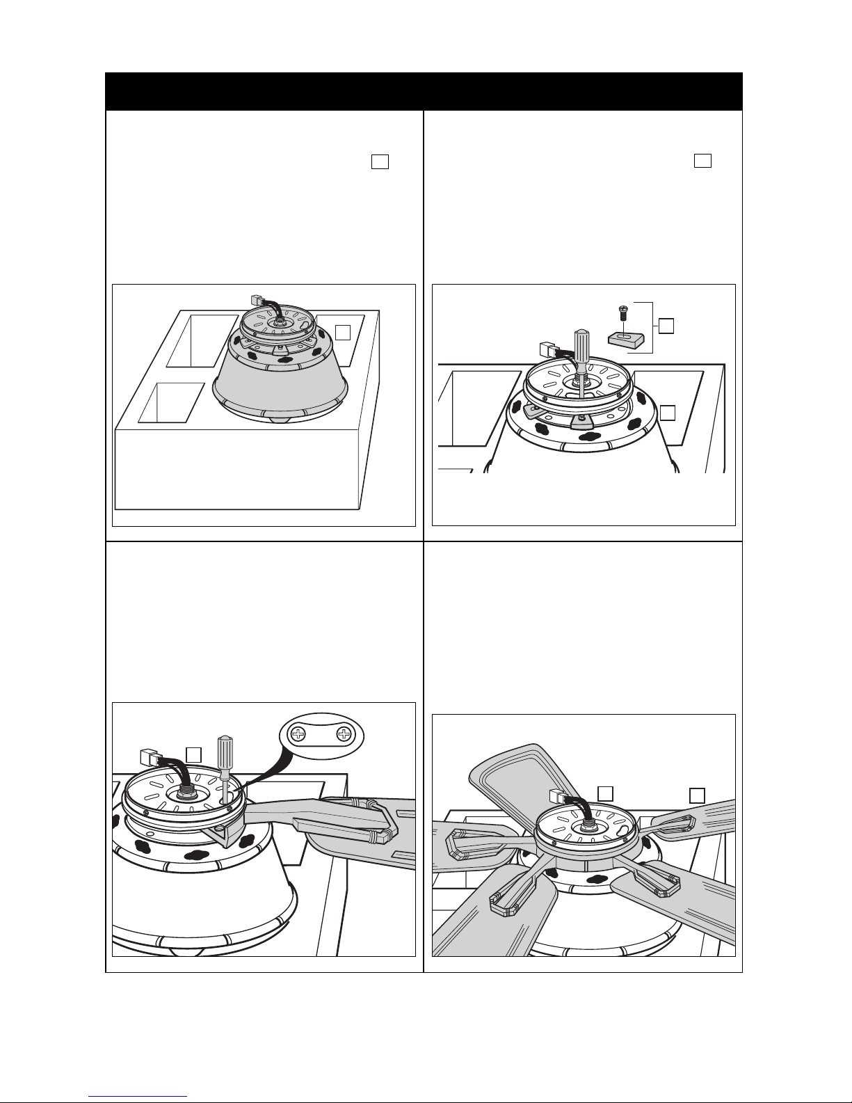
Rotate the motor and install each of the remaining four
blade assemblies onto the motor hub following the previous
procedure.
After all five blade assemblies are installed, securely
tighten all ten blade assembly screws to the motor hub in a
clockwise rotation.
This completes the blade installation.
12
Tommy Bahama • 04/2013 email@carrollparts.com • 1-800-875-3545
4.20 4.21
Locate a blade assembly and slide the end of the blade
holder onto the motor hub. Align the pre-installed screws
with the threaded holes on the motor hub. Use the switch
plate viewing window to view the screws. Attach the
screws to the motor hub by placing the tip of a Phillips
screwdriver through the viewing window and loosely
tighten both blade holder screws.
The fan housing assembly has five rubber spacers f that
protect the housing during shipping. These spacers must be
removed to allow installation of the blade assemblies.
Insert a phillips screw driver into the switch plate viewing
window to loosen and remove the screws and shipping
spacers from the motor hub.
Discard the spacers and spacer screws.
4.18 4.19
Carefully turn the partially assembled fan housing 4 over
and set it on the styrofoam shipping pad for blade
installation.
If fan is assembled with the 18 in. / 45.7 cm. downrod,
it will be necessary to stack both styrofoam pads on top of
the shipping carton to accomodate the downrod length.
Punch holes through the foam to allow the downrod and
ceiling cover to pass through the styrofoam.
4
f
4
4
4
g
5. How to Remove the Light Kit from the Fan
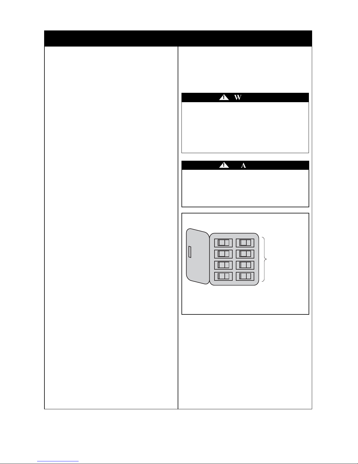
5.2
Locate and remove the small orange wire connectors 10c
attached to the blue and black wires (labeled "For Light Kit
Connection") and the two white wires (labeled "For Light
Kit Connection"). Retain the wire connectors 10c for
future use.
5.1
Locate the light kit assembly 10 and place it on a padded
work surface. Position it so that the wires are visible.
The light kit consists of two major components:
1. Switch Cover Assembly 10a .
2. Light Fitter Assembly 10b .
Turning off wall switch is not sufficient. To avoid
possible electrical shock, be sure electricity is turned
off at the main fuse or circuit breaker box before
wiring. All wiring must be in accordance with
National and Local codes and the ceiling fan must be
properly grounded as a precaution against possible
electrical shock.
!
WARNING
This ceiling fan can be installed without the light kit.
If you would like to install your fan without a light kit, please follow the below instructions.
Skip to Section 6 if you wish to install the light kit assembly on your ceiling fan.
If the light kit is already assembled to the fan, and you want to remove it, reverse Section 6 assembly instructions
to uninstall the light kit assembly and then follow Section 5 instructions to disassemble the light fixture from the
switch cover.
13
Tommy Bahama • 04/2013 email@carrollparts.com • 1-800-875-3545
5.3
On the switch cover in the center is a threaded tube, you
will find a hex nut h (1/8-27 NPS) and i lock washer.
Loosen and remove the hex nut h with a 14 mm. end
wrench, and the lockwasher i . Retain both for the next
step.
10c10c
10b
10a
h
i
10
5. How to Remove the Light Kit from the Fan (Continued)
Using a phillips screwdriver, remove the three pre-installed
#8-32 x 0.3 in. / 0.8 cm. flat head screws 22 from switch
housing plate j and retain for future installation.
14
5.6 5.7
Locate the 1/8-27 NPS switch cover screw 19 from the
hardware kit. Firmly attach the screw into the bottom
threaded hole of the switch cover using a phillips
screwdriver.
The light fitter 10b can now be removed from the switch
cover 10a by unscrewing the switch cover off the light
fitter’s threaded nipple in a counter-clockwise direction.
Reattach the lock washer i and hex nut h to the fitter’s
nipple and safely store the light fitter for future use.
5.4
5.5
Tommy Bahama • 04/2013 email@carrollparts.com • 1-800-875-3545
Straighten the frayed strands of the switch cover blue and
white wires in preparation to re-install the wire connectors
With two saved wire connectors 10c attach one to the bare
blue wire and one to the bare white wire of the switch cover
by twisting the connector in a clockwise direction until the
connector is fully threaded onto the wire. These wires must
be kept separate.
Gently pull on the connectors to ensure they are firmly
tightened onto the wires and will not fall off.
Check the connectors to ensure no bare wire strands are
visible.
10a
10b
h
i
10c
10c
10a
19
19
x 1
22
j
22
x 3
 Loading...