

Tommy Bahama BAHAMA BREEZES, Bahama Breezes TB344AP00, Bahama Breezes TB344CW00, Bahama Breezes TB344BBR00, Bahama Breezes TB344DBZ00 Owner's Manual
XXXXXXXXXXXXXXXXXXXXXXXXXXXXXXXXXXXXXXXXXXXXXXXXXXXXXXXXXXXXXXXXXXXXXXXXXXXXXXXX
XXXXXXXXXXXXXXXXXXXXXXXXXXXXXXXXXXXXXXXXXXXXXXXXXXXXXXXXXXXXXXXXXXXXXXXXXXXXXXXXXXXXXXXXXXXXXXXXXXXXXXXXXXXXXXX
XXXXXXXXXXXXXXXXXXXXXXXXXXXXXXXXXXXXXXXXXXXXXXXXXXXXXXXXXXXXXXXXXXXXXXXXXXXXXXXX
XXXXXXXXXXXXXXXXXXXXXXXXXXXXXXXXXXXXXXXXXXXXXXXXXXXXXXXXXXXXXXXXXXXXXXXXXXXXXXXXXXXXXXXXXXXXXXXXXXXXXXXXXXXXXXX
Net Weight:
19.0 Lbs.
Part No. F40BP728900001 Form No. BP7289-1
READ AND SAVE THESE INSTRUCTIONS
TB344AP00
Antique Pewter
TB344BBR00
Brushed Brass
TB344CW00
Colonial White
TB344DBZ00
Distressed Bronze
BAHAMA BREEZES
Damp Location
Ceiling Fan Owner's Manual
Model Numbers
BP7289 Tommy Bahama TB344 2/26/09 10:11 AM Page 1
WARNING: To avoid fire, shock, and serious personal injury, follow these
instructions.
Safety Instructions
1. Read your ownerÕs manual carefully and keep it for future reference.
2. Before servicing or cleaning unit, switch power off at service panel and lock
service panel disconnecting means to prevent power from being switched on
accidentally. When the service disconnecting means cannot be locked, securely
fasten a warning device, such as a tag, to the service panel.
3. Be careful of the fan and blades when cleaning, painting, or working near the
fan. Always turn off the power to the ceiling fan before servicing.
4. Do not put anything into the fan blades while they are turning.
5. Do not operate reversing switch until fan blades have come to a complete stop.
Additional Safety Instructions for Installation
1. To avoid possible shock, be sure electricity is turned off at the fuse box before
wiring, and do not operate fan without blades.
2. The installation is to be in accordance with the National Electrical Code,
ANSI/NFPA 70-1999 and Local Codes. Use the National Electrical Code if Local
Codes do not exist. The ceiling fan must be grounded as a precaution against
possible electrical shock. Electrical installation should be made or approved by
a licensed electrician.
3. The outlet box and joist must be securely mounted and capable of reliably
supporting at least 50 pounds. Use only U.L. outlet boxes listed as ÒAcceptable
for Fan SupportÓ, and use the mounting screws provided with the outlet box.
Most outlet boxes commonly used for support of light fixtures are not acceptable for fan support and may need to be replaced. Consult a qualified electrician if in doubt.
4. The fan must be mounted with the fan blades at least 7 feet from the floor to
prevent accidental contact with the fan blades.
5. Follow the recommended instructions for the proper method of wiring your
ceiling fan. If you do not know enough about electrical wiring, have your fan
installed by a licensed electrician.
NOTE: This fan is suitable for use with solid-state speed controls.
WARNING: To avoid fire, shock or injury, do not use a Tommy Bahama or any
other brand of control not specifically approved for this fan.
WARNING: This product is designed to use only those parts supplied with this
product and/or any accessories designated specifically for use with this product by
Emerson Electric Co. Substitution of parts or accessories not designated for use
with this product by Emerson Electric Co. could result in personal injury or
property damage.
WARNING: To reduce the risk of personal injury, do not bend the blade flange
when installing the blade flanges, balancing the blades or cleaning the fan. Do not
insert foreign objects in between rotating fan blades.
!
WARNING
DATE CODE:
The date code of this fan may be found on the box, stamped in ink on a white label.
You should record this data above and keep it in a safe place for future use.
2
BP7289 Tommy Bahama TB344 2/26/09 10:11 AM Page 2
3
THIS FAN IS SUITABLE FOR DAMP LOCATIONS SUCH AS
COVERED PORCHES, COVERED PATIOS, AND COVERED DECKS...
ANYWHERE THERE IS A ROOF OVERHEAD.
Tools Needed for Assembly
One Phillips head screwdriver
One wire stripper
One stepladder
One 5/32Ó hex wrench (supplied)
Four wire connectors (supplied)
Materials
Wiring, outlet box and box connectors must be of type required by the
local code. The minimum wire would
be a 3-conductor (2-wire with
ground) of the following sizes:
This Manual Is Designed to Make it as Easy as Possible for You to
Assemble, Install, Operate and Maintain Your Ceiling Fan
Installed Wire Length Wire Size A.W.G.
Up to 50 ft. 14
50-100 ft. 12
Before assembling your ceiling fan,
refer to section on proper method of
wiring your fan (page 9). If you feel you
do not have enough wiring knowledge
or experience, have your fan installed
by a licensed electrician.
!
WARNING
Unpacking Instructions
For your convenience, check-off boxes are provided next to each step. As each
step is completed, place a check mark in the box. This will insure that all
steps have been completed and will be helpful in finding your place should
you be interrupted.
Do not install or use fan if any part is
damaged or missing. Call Toll-Free:
1-800-654-3545
!
WARNING
This product is designed to use only
those parts supplied with this product
and/or any accessories designated
specifically for use with this product by
Emerson Electric Co. Substitution of
parts or accessories not designated for
use with this product by Emerson
Electric Co. could result in personal
injury or property damage.
!
WARNING
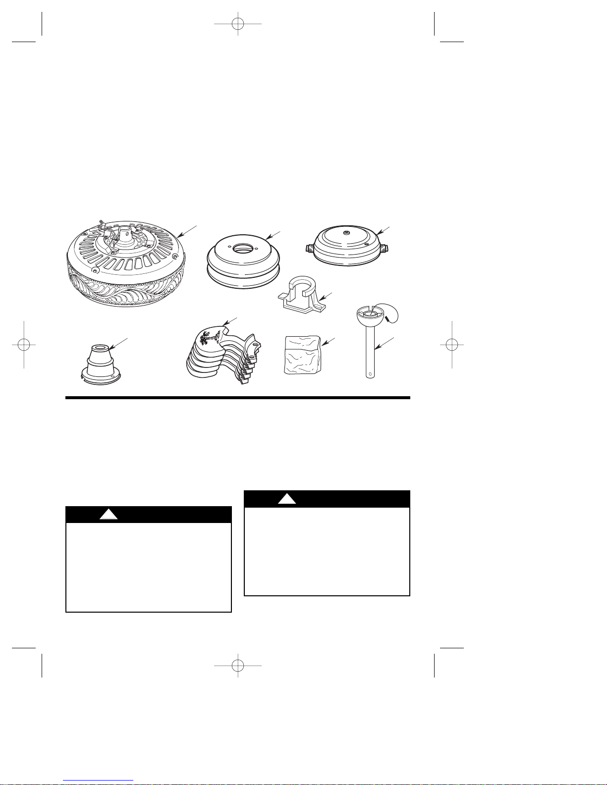
1. Open styrofoam unit containing
fan. Remove top half of styrofoam
unit. Remove parts and check to
see that you have received the following parts:
NOTE: If you are uncertain of part
description, refer to exploded view
illustration.
a. Fan motor and housing assembly
b. One ceiling cover
c. One motor cover
d. Five blade flanges
e. One hanger bracket
f. One hanger ball/downrod assembly
g. One switch housing cover
BP7289 Tommy Bahama TB344 2/26/09 10:11 AM Page 3
Your new ceiling fan will require a
grounded electrical supply line of
120 volts AC, 60 Hz, 15 amp circuit.
The outlet box must be securely
anchored and capable of withstanding a load of at least 50 pounds.
4
To reduce the risk of fire, electric
shock, or personal injury, mount fan to
outlet box marked ÒAcceptable for Fan
SupportÓ, and use screws supplied with
outlet box. Most outlet boxes commonly used for support of light fixtures are
not acceptable for fan support and may
need to be replaced. Consult a qualified
electrician if in doubt.
!
WARNING
h. One loose parts bag containing:
1. One 5/16-18 x 1/4Ó setscrew
2. One 5/32Ó hex wrench
3. Two 1Ó threaded studs
4. Two 1-1/4Ó threaded studs
5. Four knurled knobs
6. Four lockwashers
7. Four wire connectors
8. One hibiscus pendant
9. One bell pendant
10. Two couplings
11. One clevis pin/hairpin clip
assembly
Electrical Requirements
12. Eleven 10-32 x 3/4Ó oval head
screws
13. Twenty-one 10-32 x 5/16Ó
Phillips pan head screws
14. Twenty-one #10 flat washers
15. Two 8-32 x 3/8Ó pan head
screws
NOTE: Place the parts from the loose
parts bags in a small container to
keep them from being lost. If any
parts are missing, contact your local
retailer or catalog outlet for replacement before proceeding.
If your fan is to replace an existing
ceiling light fixture, turn electricity
off at the main fuse or circuit breaker box at this time and remove the
existing light fixture.
Turning off wall switch is not sufficient. To avoid possible electrical
shock, be sure electricity is turned off
at the main fuse or circuit breaker box
before wiring. All wiring must be in
accordance with National and Local
codes and the ceiling fan must be properly grounded as a precaution against
possible electrical shock.
!
WARNING
BP7289 Tommy Bahama TB344 2/26/09 10:11 AM Page 4
C
A
B
E
D
H
G
F
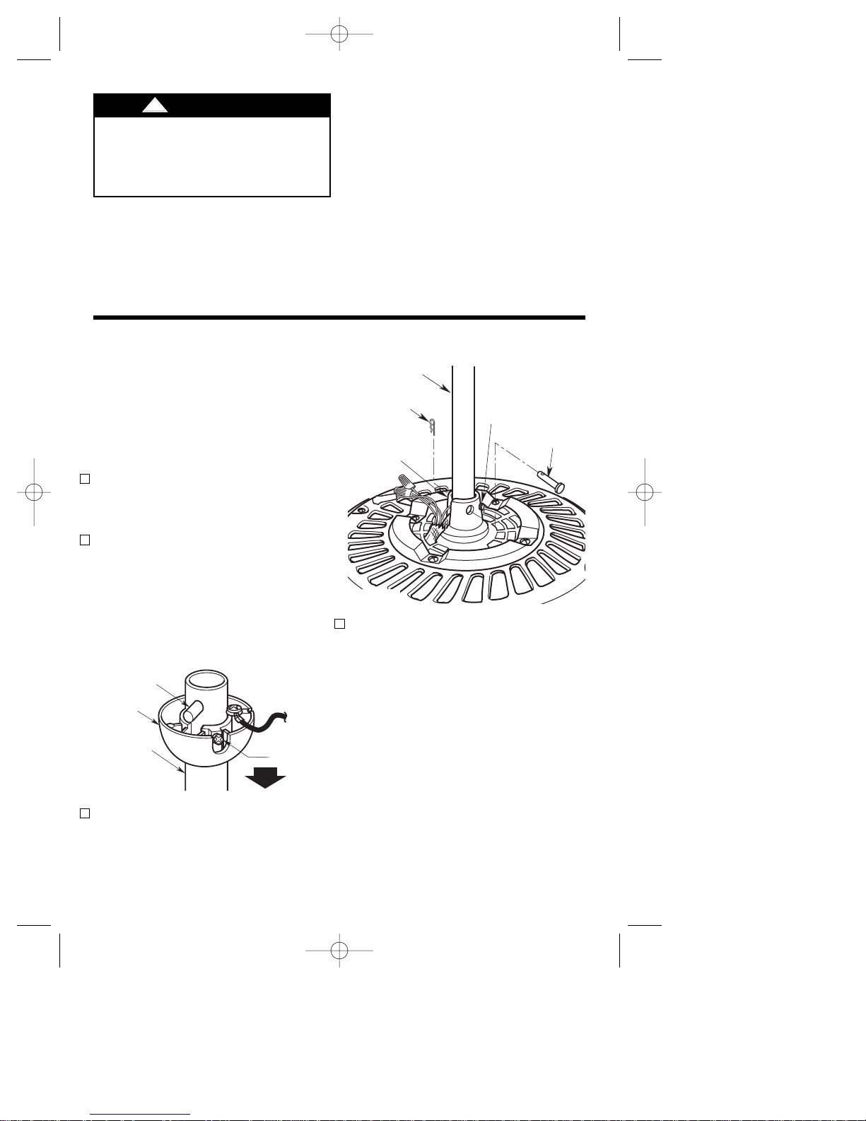
DOWNROD
CLEVIS
PIN
5/16-18" x 1/4"
SETSCREW
MOTOR
COUPLING
HAIRPIN
CLIP
5
IMPORTANT: If you are going to use
a Tommy Bahama remote control and
receiver to control your fan, perform
the instructions in this OwnerÕs
Manual in conjunction with the
instructions contained in the remote
control/receiver OwnerÕs Manual.
1. Remove the fan motor and housing
assembly from the styrofoam packaging and position it so that the
top of the motor is facing you.
2. Remove the hanger ball from the
downrod by loosening the
setscrew in the hanger ball until
the ball falls freely down the downrod (Figure 1). Remove the pin
from the downrod, then remove
the hanger ball. Retain the pin and
hanger ball for reinstallation in
step 8.
3. Separate, untwist and unkink the
three motor leads. Route the
motor leads through the downrod
and seat the downrod in the motor
coupling (Figure 2).
Figure 1
Figure 2
The Tommy Bahama TB344 Series
Ceiling Fan is designed to be operated from wall switch(es), or from a
Tommy Bahama remote control/
transmitter. There are no controls
supplied with the ceiling fan.
How to Assemble Your Ceiling Fan
4. Align the clevis pin holes in the
downrod with the holes in the
motor coupling. Install the clevis
pin and secure with the hairpin
clip (Figure 2). (Pin and clip are
supplied in loose parts bag.) The
clevis pin must go through the
holes in the motor coupling and
the holes in the downrod. Push the
straight leg of the hairpin clip
through the hole near the end of
the clevis pin until the curved portion of the hairpin clip snaps
around the clevis pin. The hairpin
clip must be properly installed to
prevent the clevis pin from working loose. Pull on the downrod to
make sure the clevis pin is properly installed.
To avoid possible fire or shock, follow
all wiring instructions carefully.
Any electrical work not described in
these instructions should be done or
approved by a licensed electrician.
!
WARNING
IMPORTANT: Your ceiling fan and
optional Tommy Bahama remote control will not function properly, and
may be damaged, it used with any
wall dimmer switch or control other
than Tommy Bahama Wall Control,
Model No. TBSW02. Use only this
Tommy Bahama Wall Control or a
listed general use on/off wall switch.
BP7289 Tommy Bahama TB344 2/26/09 10:11 AM Page 5
PIN
HANGER
BALL
DOWNROD
SETSCREW
 Loading...