

Page 1

O:\Cad\JME INSTRUCTION SHEETS\1914975A.dwg
S
IMPLI
LEX 2000
F-
®
COUNTER/CABINET MOUNT DISPENSERS
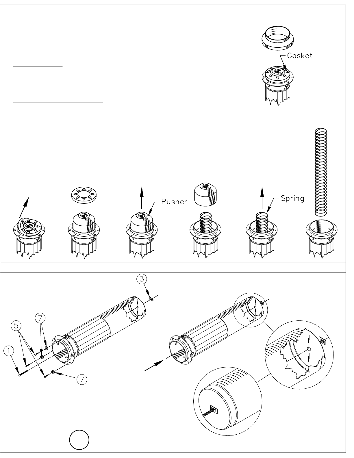
FOR IN-COUNTER MOUNTING:
REFER TO CHART AND DIAGRAM BELOW TO ESTABLISH
MOUNTING HOLE SIZE AND MINIMUM CLEARANCE FOR
EASE OF INSTALLATION AND SERVICE. ALLOW AT LEAST
1/4" (6.35 mm) BETWEEN DISPENSERS (DIMENSION "A")
1.
Lay out and cut hole(s) for dispenser.
2.
Remove gasket (2), pusher (3), and spring (4). (See Figure 1)
3.
Pre-drill holes for #8 x 3/4" mounting screws (5). Slide dispenser into
hole and secure through keyhole slots with screws and studs (7) provided.
(See Figure 2)
4.
Reassemble dispenser. Clamp ring (1) is installed
over the gasket (2) as last step in reassembly. (See Figure 1)
LOADING THE DISPENSER:
Your Modular SIMPLI-FLEX dispenser is completely self-adjusting
and can dispense virtually any size or shape of cup!
1.
Unwrap cups and gently push into completely assembled dispenser tube,
BOTTOM OF CUP FACING OUT. (See Figure 3)
®
CLEANING THE DISPENSER:
Your Modular SIMPLI-FLEX dispenser is designed to provide
an easy means of dispensing. The dispenser can be disassembled
using only a phillips screwdriver to make regular cleaning simple
anad painless! Please clean dispenser before use. Regular cleaning
will prolong the life of the dispenser, keep it looking new and
ensure sanitary dispensing.
Remove clamp ring (1), screws (5), and studs (7), to remove
1.
dispenser from mounting location. (See Figure 2
illustration C thru A)
Remove gasket (2), pusher (3), and spring (4).
2.
(See Figure 1)
Clean clamp ring and gasket in hot, soapy water. Air dry.
3.
NOTE: these parts are dishwasher safe.
Rinse dispenser tube and wipe with a non-toxic cleaner/sanitizer.
4.
Reassemble dispenser in reverse of above. (See Figure 2
5.
illustration A thru C)
®
S
IMPLI
LEX 2000
F-
®
COUNTER/CABINET MOUNT DISPENSERS
CATALOG NUMBER
1015023
Elevator type, counter/cabinet mount, for paper, plastic, foam cups
APPLICATION
SF2000
INCHES (METRIC)
A
B
C
D
(A)
6-3/4 (172mm)
23-1/32 (585mm)
5-1/4 (133mm)
5-1/2 (140mm)
(B)
(C)
DESCRIPTION
SF2000
FIGURE 2
MODULAR
DISPENSING SYSTEMS
DIVISION OF TOMLINSON INDUSTRIES
13700 Broadway Ave.
Cleveland Ohio 44125-1992
Phone: 216/587-3400
Fax: 216/587-0733
www.tomlinsonind.com
World Class, Worldwide
Tomlinson Industries 1999
©
NSF
FIGURE 1
FIGURE 3
®
(Page 1)
Form 1914975 Printed in the U.S.A. 9/03
Patent Pending
1 of 2
Page 2
O:\Cad\JME INSTRUCTION SHEETS\1914975B.dwg
S
IMPLI
-
LEX 2000
F
®
COUNTER/CABINET MOUNT DISPENSERS
FOR CABINET MOUNTING: (optional)
For reference to instructions below use exploded view of cup dispenser (See page 1 Figure 1).
We recommend that the dispenser be supported from the rear when used in horizontal applications.
PART 1: Disassemble
Remove gasket from lip of dispenser (See Figure 6 illustration B and C).
1.
NOTE: CAUTION when removing gasket, pusher may be under small amount of spring tension.
2.
Remove pusher from spring (See Figure 6 illustration D and E).
Remove spring from dispenser (See Figure 6 illustration F and G).
3.
PART 2: Assemble Mounting Hardware
1.
Remove hardware from packet. Hardware kit consists of 1 - 10-32x1-3/4 sloted round head
screw(1), 3 - 8-18x3/4 phillip head screw(2), 1 - 10-32 speed clip(3), and 3 - studs(7) (See Figure 7).
Grasp the head of the screw(1) with your hand and lead it inside the open end of dispenser
2.
to the bottom(See Figure 8 illustration I).
3.
With screw(1) in hand, lead threads through hole in bottom of dispenser, ONLY threads of
screw(1) will pass through this hole(See figure 8 illustration I).
While holding screw(1) firmly to the bottom from inside the dispenser, attach speed clip(3)
4.
by threading it on screw(1) as shown in figure 8 illustration J.
While continuing to holding screw(1) to the bottom, tighten speed clip(3) firmly to bottom
5.
of dispenser (See Figure 8 illustration K).
Reassemble dispenser in reverse order. Clamp ring is installed
6.
over the gasket as last step in reassembly. (See Figure 6 illustration G thru A)
FIGURE 6
(A)
(B)
S
IMPLI
F
-
LEX 2000
(C)
FIGURE 7
(D)
®
ASSEMBLE CABINET MOUNTING HARDWARE
(E) (F)
FIGURE 8
(I)
(K)
(G)
(J)
MODULAR
DISPENSING SYSTEMS
DIVISION OF TOMLINSON INDUSTRIES
13700 Broadway Ave.
Cleveland Ohio 44125-1992
Phone: 216/587-3400
Fax: 216/587-0733
www.tomlinsonind.com
World Class, Worldwide
Tomlinson Industries 1999
©
NSF
®
(Page 2)
REVERSE ANGLE
Form 1914975 Printed in the U.S.A. 9/03
Patent Pending
1 of 2
Page 3

O:\Cad\JME INSTRUCTION SHEETS\1914975C.dwg
S
IMPLI
-F
LEX 2000
®
COUNTER/CABINET MOUNT DISPENSERS
CHANGING CUP SIZE:
For reference to instructions below use exploded view of cup dispenser (See page 1 figure 1).
1.
Remove cup(s) from dispenser (See figure 4 illustration A and B).
2.
Remove decorator clamp ring (See figure 4 illustration C and D).
3.
Remove gasket from lip of dispenser (See figure 4 illustration E and F).
NOTE: CAUTION when removing gasket, pusher may be under small amount of spring tension.
Replace gasket with desired size (See Figure 5 reference chart at bottom of page).
4.
5.
Reassemble dispenser in reverse order (See figure 4 illustration F thru A)
FIGURE 4
(A)
(B) (C)
(D)
S
IMPLI LEX 2000
FIGURE 5
-
F
(E)
®
GASKET SIZE REFERENCE
(F)
MODULAR
DISPENSING SYSTEMS
DIVISION OF TOMLINSON INDUSTRIES
13700 Broadway Ave.
Cleveland Ohio 44125-1992
Phone: 216/587-3400
Fax: 216/587-0733
www.tomlinsonind.com
World Class, Worldwide
Tomlinson Industries 1999
©
NSF
Dimension Letter:
Cup Ounce:
Cup Lip Diameter:
(Metric)
®
GASKET REFERENCE CHART
"5B" "5A"
3-1/2 oz. - 14 oz.
2-1/4" - 3-7/8"
(57mm - 98mm)
(Page 3)
14 oz. - 32 oz.
3-1/2" - 4-7/16"
(89mm - 113mm)
"5E"
32 oz. - 44 oz.
4-1/4" - 4-5/8"
(108mm - 117mm)
Form 1914975 Printed in the U.S.A. 9/03
Patent Pending
1 of 2
 Loading...