

Page 1

7210 / 7220
IP Centrex Telephone
Network Administration Guide
13-102865 Rev. K
April 2003
Page 2

This document applies to telephone software version 01.02.18.
© 2003, Tone Commander Systems, Inc. All rights reserved.
Printed in USA
Tone Commander is a registered trademark of Tone Commander Systems, Inc.
Windows and Windows NT are registered trademarks of Microsoft Corp.
Page 3

Tone Commander 7210/7220 Network Administration Guide
Contents
Overview ......................................................................................................................................4
DHCP Server Configuration .......................................................................................................4
Windows 2000 Server ..............................................................................................................4
Windows NT Server................................................................................................................11
TFTP Server Configuration.......................................................................................................15
Telephone Configuration Update.............................................................................................16
Automatic Update ...................................................................................................................16
Manual Update .......................................................................................................................17
Quality of Service......................................................................................................................18
Ethernet Layer 2 802.1Q Options...........................................................................................19
IP Layer 3 Differentiated Services (DiffServ)..........................................................................20
Codecs ...................................................................................................................................20
Troubleshooting........................................................................................................................24
_____________________________________
Network Troubleshooting........................................................................................................24
Call Control Troubleshooting ..................................................................................................26
Telnet......................................................................................................................................27
Reference...................................................................................................................................28
DHCP Messages ....................................................................................................................28
TFTP Server Configuration File Formats................................................................................29
Port Usage..............................................................................................................................32
13-102865 Rev. K Page 3 of 32
Page 4

Overview
Each telephone on the network must be assigned a unique IP address. The address can be assigned
automatically by a DHCP server, or entered manually at the phone.
Telephone operating software can be updated from a TFTP server. The update process can be initiated
manually at the phone, or set to occur daily at a preset time. Operating software is automatically updated
during power-up or reset.
Procedures for setting up DHCP and TFTP servers, and updating the phone software, are explained
below.
_____________________________________
This manual is intended for use by network administrators.
DHCP Server Configuration
The DHCP server requires a scope of IP addresses that can be assigned to the phones. The scope must
be configured with the router address, vendor-specific info, and the TFTP server address.
Examples for Windows
®
2000 Server and Windows NT® Server follow.
_____________________
Windows 2000 Server
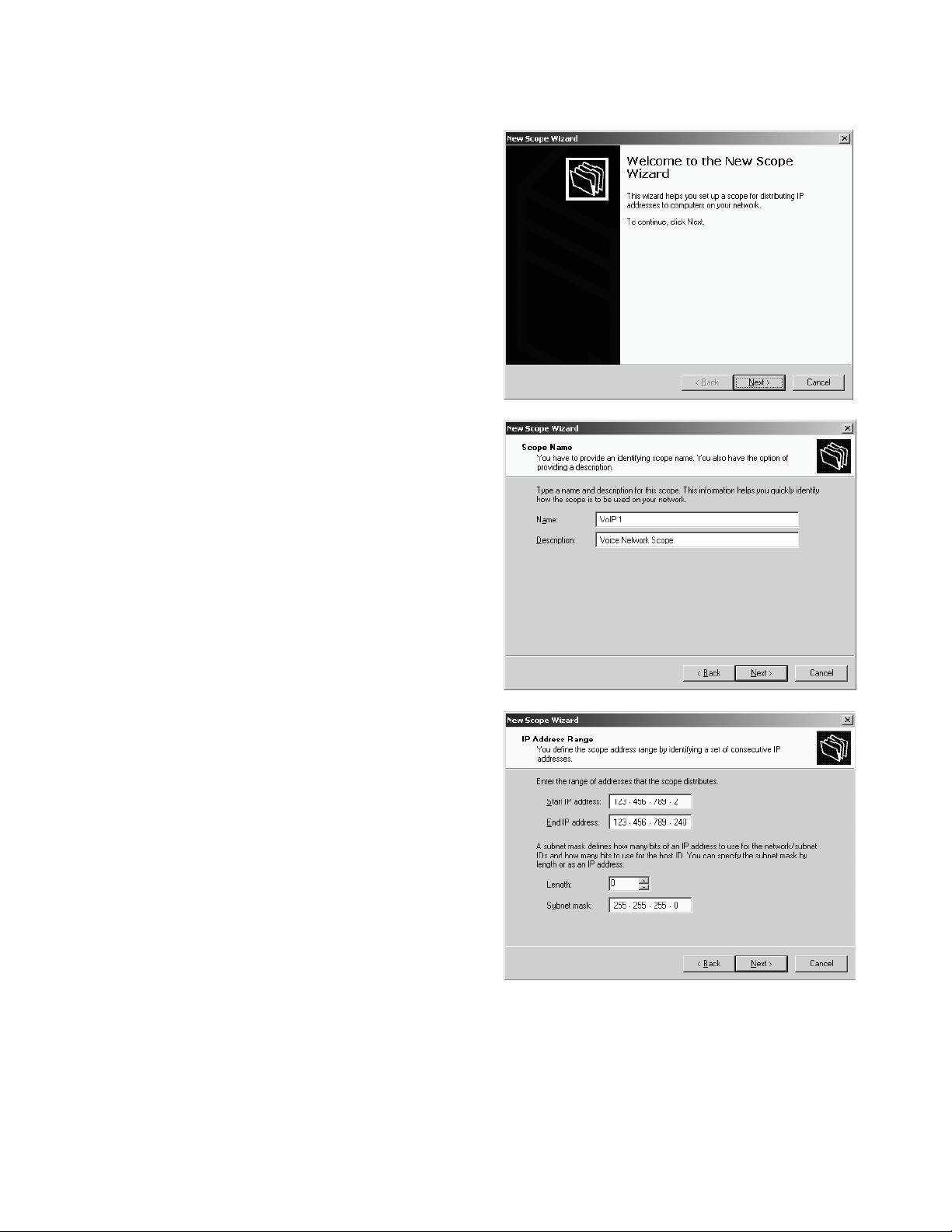
Run DHCP from the Administrative Tools menu.
Add Server
You can use an existing DHCP server for assigning IP
addresses to the telephones, or add a new server.
1. Select Add Server from the Action menu.
2. Enter the IP address of the DHCP server in the
This server field.
3. Click OK.
Add Scope
1. Select the DHCP server you will use for assigning IP addresses to the telephone.
2. Select New Scope from the Action menu to run the New Scope Wizard.
Page 4 of 32 13-102865 Rev. K
Page 5
Tone Commander 7210/7220 Network Administration Guide
3. Click Next to show the Scope Name screen.
4. Enter a name and description for the scope.
5. Enter the start and end of the IP address range
that can be assigned to telephones.
6. Enter the appropriate subnet mask.
13-102865 Rev. K Page 5 of 32
Page 6
7. If you need to exclude some IP addresses from
the range, enter them here, otherwise click Next.
8. You can use the defaults, or enter a new lease
duration for telephone IP addresses. Lease
duration should be set to 7 days or longer.
When the lease expires the phone
shows a diagnostic display if idle,
while attempting to negotiate a new IP
address lease at preset intervals. If
the phone is active, the call will be
unaffected and the diagnostic display
will be shown when the call is cleared.
If the same IP address is offered by
the DHCP server, the phone returns to
operation without restarting, otherwise
the phone will restart after receiving a
new IP address.
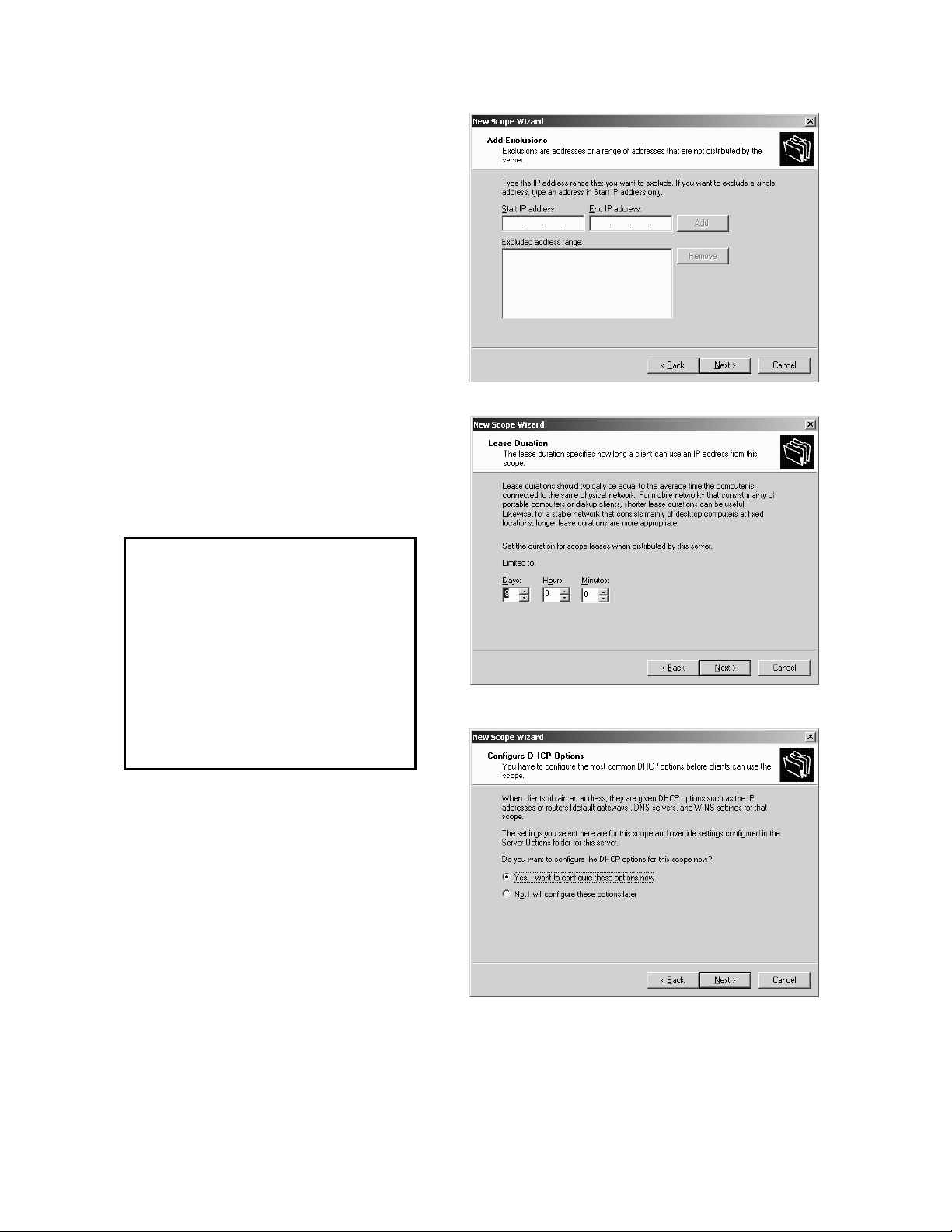
9. Select Yes on the Configure IP Options screen.
Page 6 of 32 13-102865 Rev. K
Page 7
Tone Commander 7210/7220 Network Administration Guide
10. Enter the IP address of the router or default
gateway.
11. If needed, enter the parent domain name, DNS
servers, and WINS servers on the next two
screens.
12. Select Yes to activate this scope.
13. Click Finish on the next screen.
Scope Options
1. In the Tree pane, expand (double-click or ‘+’) the
VoIP DHCP server.
2. Expand the Scope entry for the telephone IP
address range.
3. Right-click Scope Options, then select Configure
Options from the menu.
13-102865 Rev. K Page 7 of 32
Page 8
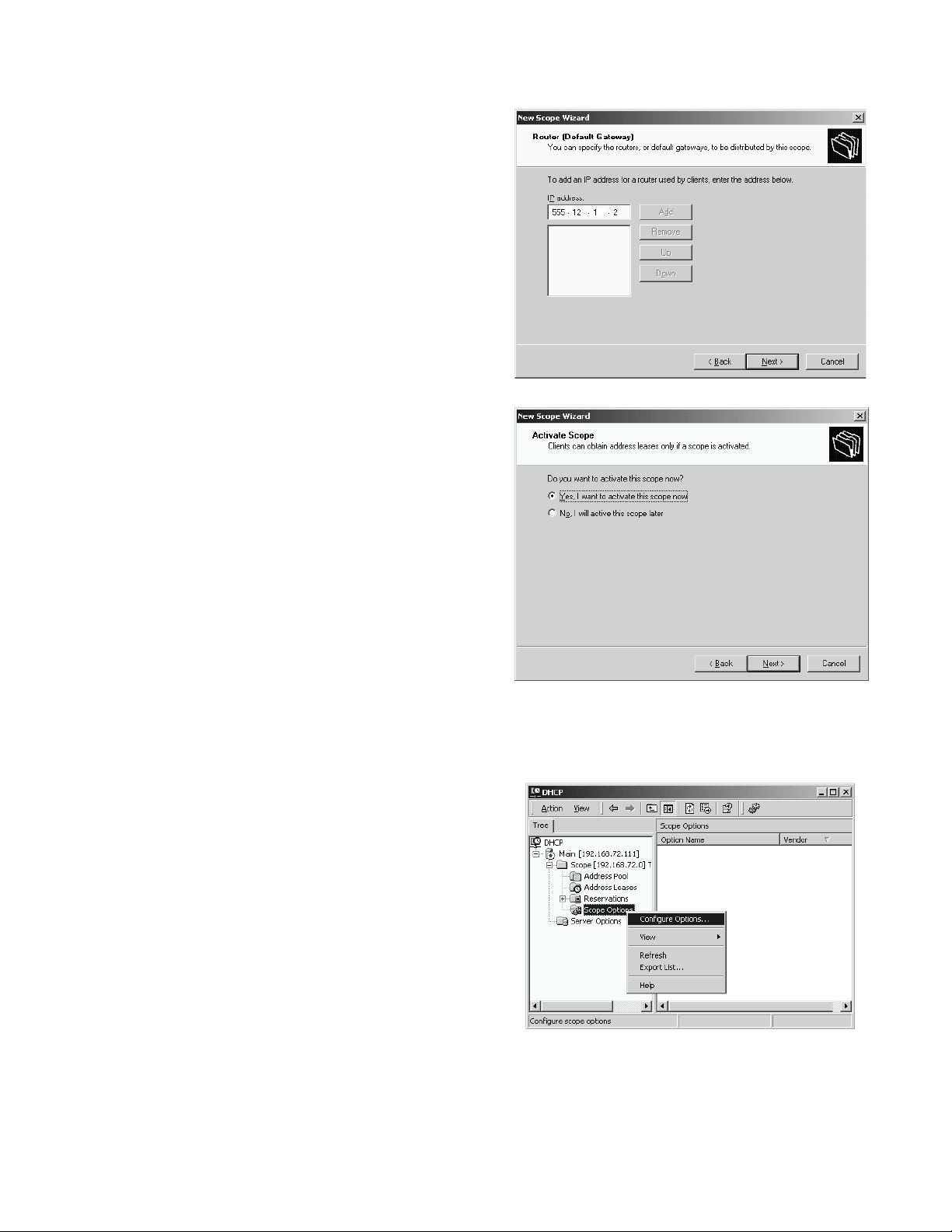
4. Check the box next to 002 Time Offset.
5. Select 002 Time Offset. If your network time
server is set to UTC time, enter the hex value for
your location's offset from UTC time in seconds. If
your network time server is set to local time, enter
0.
Time Zone Offset
Pacific Standard Time 0xffff8f80
Pacific Daylight Time 0xffff9d90
Mountain Standard Time 0x ffff9d90
Mountain Daylight Time 0x ffffaba0
Central Standard Time 0xffffaba0
Central Daylight Time 0xffffb9b0
Eastern Standard Time 0xffffb9b0
Eastern Daylight Time 0xffffc7c0
6. Make sure the box next to 003 Router is checked.
7. The router IP address may have been entered
from the New Scope Wizard. If not, select 003
Router, enter the IP address, then click Add.
8. Check the box next to 004 Time Server.
9. Select 004 Time Server, enter the IP address of
the SNTP time server for your network, then click
Add.
Page 8 of 32 13-102865 Rev. K
Page 9
Tone Commander 7210/7220 Network Administration Guide
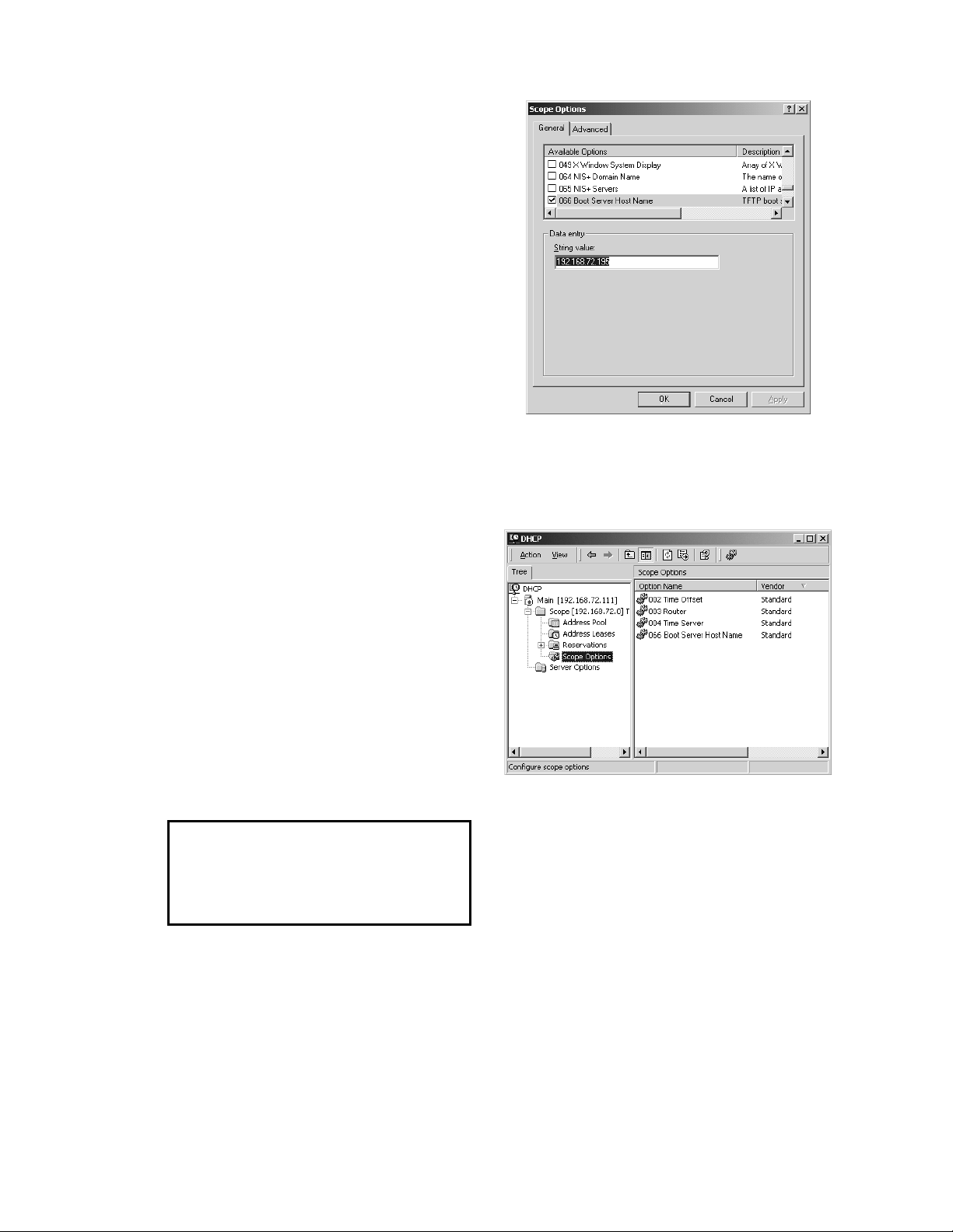
10. Check the box next to 066 Boot Server Host
Name.
11. Select 066 Boot Server Host Name, then enter
the TFTP boot server’s IP address in the String
value field.
12. Click OK.
13. "002 Time Offset", “003 Router”, "004 Time
Server", and “066 Boot Server Host Name”
should now appear in the Scope Options pane.
To preclude the issuance of a new IP
address each time the phone reboots, it
is recommended that ICMP ping prior
address assignment be disabled at the
DHCP server.
13-102865 Rev. K Page 9 of 32
Page 10
Windows NT Server
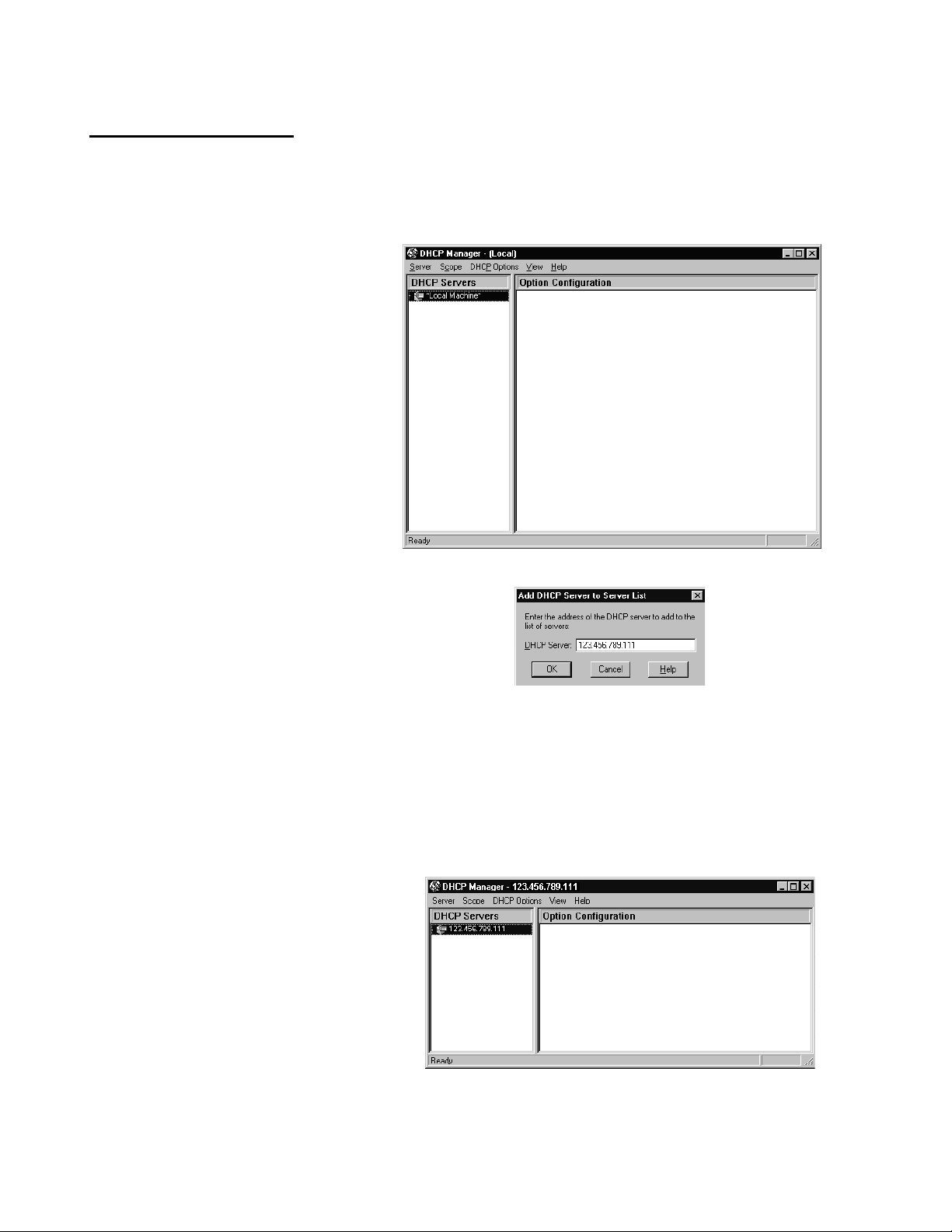
Run DHCP Manager from the Administrative Tools menu.
Add Server
You can use an existing DHCP server for
assigning IP addresses to the telephones,
or add a new server.
1. To add a server, select Server from
the File menu, then select Add.
2. Enter the address of the new DHCP server.
Add Scope
1. Select the DHCP server.
2. Select Create from the Scope menu.
Page 10 of 32 13-102865 Rev. K
Page 11

Tone Commander 7210/7220 Network Administration Guide
3. Enter the start and end of the IP address
range that can be assigned to telephones.
4. Enter the appropriate subnet mask.
5. Enter a name for the scope in the Name field,
and an optional description in the Comment
field.
6. Exclude addresses from the range and
change the lease duration if needed. Lease
duration should be set to 7 days or longer.
When the lease expires the phone
shows a diagnostic display if idle,
while attempting to negotiate a new IP
address lease at preset intervals. If
the phone is active, the call will be
unaffected and the diagnostic display
will be shown when the call is cleared.
If the same IP address is offered by
the DHCP server, the phone returns to
operation without restarting, otherwise
the phone will restart after receiving a
new IP address.
7. Click OK.
8. Click Yes to activate the scope.
13-102865 Rev. K Page 11 of 32
Page 12

Scope Options
1. Select 002 Time Offset from the Unused options
list and click Add to add it to the Active Options
list.
2. Click Edit Array.
3. If your network time server is set to UTC time,
enter the hex value for your location's offset from
UTC time in seconds. If your network time server
is set to local time, enter 0. Click Add.
4. Click OK.
Time Zone Offset
Pacific Standard Time 0xffff8f80
Pacific Daylight Time 0xffff9d90
Mountain Standard Time 0x ffff9d90
Mountain Daylight Time 0x ffffaba0
Central Standard Time 0xffffaba0
Central Daylight Time 0xffffb9b0
Eastern Standard Time 0xffffb9b0
Eastern Daylight Time 0xffffc7c0
5. Add 003 Router to the Active Options list.
6. Click Edit Array.
7. Enter the router IP address, then click Add.
8. Click OK.
Page 12 of 32 13-102865 Rev. K
Page 13

Tone Commander 7210/7220 Network Administration Guide
9. Add 004 Time Server to the Active Options list.
10. Click Edit Array.
11. Enter the IP address of the SNTP time server for
your network, then click Add.
12. Click OK.
13. Add 066 Boot Server Host Name to the Active
Options list.
14. Enter the TFTP boot server’s IP address in the
String field.
15. Click OK.
16. "002 Time Offset", “003 Router”, "004 Time
Server, and “066 Boot Server Host Name”
should now appear in the Scope Options
pane.
To preclude the issuance of a new IP
address each time the phone reboots, it
is recommended that ICMP ping prior
address assignment be disabled at the
DHCP server.
13-102865 Rev. K Page 13 of 32
Page 14

TFTP Server Configuration
Telephones download configuration information and software upgrades from a TFTP server. The TFTP
server’s IP address must be identified during DHCP server setup, or entered manually in the phone if
DHCP is disabled.
Configuration packages distributed by Tone Commander include a phone boot ROM image file,
application software image file, two configuration files, and a Readme text file.
All files must be located in the TFTP server’s root folder .
The root folder should contain the following files:
filename.bin Boot program image.
filename.z Compressed application image.
tcs7200a.txt Configuration options not included in the standard DHCP options.
tcs7200b.txt Names the application file and boot program to be downloaded to the phone.
These files need to be in the TFTP server root folder.
The phone will attempt to download parameters or programs only if the
information in the above .txt files indicates that the phone is not at the desired
current configuration.
readme.txt information file
______________________
xxxxxxxxxxxxxx.txt Optional files allow customers to set up phones with specific configuration
parameters or program versions based on the phones’ alias (xxxxxxxxxxxxxx
in the file name, e.g., 30947701840101). Any information that is different in
this file overrides the information in the tcs7220a,b files. A separate file is
required for each phone that differs from the standard configuration or
programming as defined in tcs7200a.txt and tcs7200b.txt files.
Configuration files can be modified with any text editor. See page 29 for file format descriptions.
Page 14 of 32 13-102865 Rev. K
Page 15

Tone Commander 7210/7220 Network Administration Guide
Telephone Configuration Update
Telephone operating software and configuration parameters can be automatically updated daily at a
preset time, or manually updated.
_________________
Automatic Update
SETUP MENU
INSTL ADMIN USER
1. Select AUTO from the TFTP CONFIG
UPDATE menu.
(Setup → INSTL → UPDATE→ TFTP→ AUTO)
2. Enable TFTP Update if necessary.
3. Enter the time you want the daily update
to occur.
The minutes value is calculated based on the
MAC address of the phone, to minimize the
possibility of multiple phones simultaneously
requesting updates. You may manually enter
the minutes digits, but it is recommended that
you use the default calculated value.
INSTALLATION OPTIONS \
IP ALIAS SPID UPDATE
IP CONFIGURATION UPDATE
DHCP TFTP FLASH TELNET
TFTP CONFIG UPDATE
START AUTO
4. Press the Done key.
NOTE – For special instructions and information,
please refer to the Upgrading Notes
associated with a specific upgrade.
TFTP UPDATE= DISABLED
ENABLE
TFTP UPDATE TIME=03:26AM
DISABLE |BKSP AM/PM
13-102865 Rev. K Page 15 of 32
Page 16

Manual Update
To perform a manual update, the phone must have the TFTP server’s IP address entered manually or
downloaded via DHCP.
Manual TFTP Server Entry
SETUP MENU
INSTL ADMIN USER
1. Select TFTP from the IP ADDRESS/CONFIG
menu.
2. Enter the TFTP server address with the dial
pad.
3. Press the Done key.
Starting Manual Update
Use the TFTP CONFIG UPDATE - START option
to initiate the manual update.
INSTALLATION OPTIONS \
IP ALIAS SPID UPDATE
IP ADDRESS/CONFIG \
PHONE GATEWY TFTP iMERGE
TFTP=192.168.72.195
|BKSP CLEAR PING
SETUP MENU
INSTL ADMIN USER
INSTALLATION OPTIONS \
IP ALIAS SPID UPDATE
IP CONFIGURATION UPDATE
DHCP TFTP FLASH TELNET
TFTP CONFIG UPDATE
START AUTO
Page 16 of 32 13-102865 Rev. K
Page 17

Tone Commander 7210/7220 Network Administration Guide
Quality of Service
Quality of Service (QoS) settings can improve voice performance over a network by prioritizing voice
packets, and adjusting packet buffering and packetization rate.
These settings affect network traffic, and should not be changed unless required to correct audio
problems.
To view or change Quality of Service settings,
select QoS from the Installation Options menu.
(Setup → INSTL → More4 → More4 → QoS)
Layer 2, Layer 3, and Codecs can be selected
from the Quality of Service menu.
When finished viewing or changing any setting,
press the Done key to return to the previous
menu or the Setup key to exit Setup Mode.
______________________________
SETUP MENU
INSTL ADMIN USER
INSTALLATION OPTIONS \
IP ALIAS SPID UPDATE
INSTALLATION OPTIONS \
KEYS MODE VA PARAM
INSTALLATION OPTIONS \
QoS PASSWD RESET
QUALITY of SERVICE
L2 L3 CODECS
13-102865 Rev. K Page 17 of 32
Page 18

Ethernet Layer 2 802.1Q Options
IEEE 802.1Q allows packets to be assigned one of eight priority levels. Voice traffic with less than 10 ms
of latency is normally assigned a priority level of 6 (phone default). Network switches must support
802.1Q for this setting to have an effect. If the LAN does not support 802.1Q, this parameter should be
set to OFF.
NOTE – The Ethernet card in a PC connected to the phone must support 802.1Q, since the phone does
not add 802.1Q tagging to packet headers not generated in the phone. PC packets are passed
through without modification.
1. Select L2.
2. Select ON or OFF to enable/disable Layer 2
802.1Q support.
3. To change the priority of voice or signaling
packets, select PRIORITY, select VOICE or
SIGNAL, then enter the priority level (0-7) with
the dial pad.
4. If the network uses virtual LANs, select ID, then
enter the appropriate VLAN ID with the dial
pad.
LAYER 2 802.1Q PRIORITY
VOICE SIGNAL
QUALITY of SERVICE
L2 L3 CODECS
LAYER 2 802.1Q=ON
OFF PRIORITY ID
VOICE 802.1Q PRIORITY=6
SIGNAL 802.1Q PRIORITY=6
802.1Q VLAN ID=0000
|BKSP CLEAR
Page 18 of 32 13-102865 Rev. K
Page 19

Tone Commander 7210/7220 Network Administration Guide
IP Layer 3 Differentiated Services (DiffServ)
The Quality of Service for voice and signaling packets is determined by each service type’s Differentiated
Services Code Point (DSCP) setting. This value must be matched to network router settings. The default
setting for both voice and signaling is 46.
1. Select L3.
2. Select VOICE or SIGNAL to view or set the
DSCP value for voice or signaling packets.
3. Use the dial pad to enter a new DSCP value
(0-63).
VOICE DIFFSERV DSCP=46
|BKSP CLEAR
Codecs
Five codec selections are available. Any
codec/packet rate combination can be
disabled.
QUALITY of SERVICE
L2 L3 CODECS
LAYER 3 DIFFSERV
VOICE SIGNAL
SIGNAL DIFFSERV DSCP=46
|BKSP CLEAR
QUALITY of SERVICE
L2 L3 CODECS
1. Select CODEC.
2. Cycle through the codecs with the More
key. The display will show the codec type
(G.711, G.729A, or G.723), the packet
rate (10, 20, or 30ms), and the average
and maximum jitter delay for each enabled
codec.
3. Enable or disable codecs as required.
If more than one codec is enabled, the
selected codec is negotiated on a per-call
basis, between the list of codecs enabled
on iMerge and codecs enabled on the
phone. iMerge codecs take precedence.
You can view the negotiated codec
selection through the Packet Diagnostics
menu (see below).
CAUTION – Make sure at least one
codec that is supported by the iMerge
CFG is enabled, otherwise a voice
channel cannot be established.
4
G.711/10ms JTR=20/40ms \
DISABLE JTR
G.711/20ms JTR=35/80ms \
DISABLE JTR
G.711/30ms JTR=45/90ms \
DISABLE JTR
G729A/20ms DISABLED \
ENABLE
G.723/30ms JTR=45/90 ms\
DISABLE JTR
JTR DELAY AVE=45/MAX=90
AVE+ AVE- MAX+ MAX-
13-102865 Rev. K Page 19 of 32
Page 20

Codec Selections
G.711 – Uncompressed, 64Kbps data rate (10, 20, or 30 ms packet rate)
G.729A – Compressed, 8Kbps data rate (20 ms packet rate)
G.723 – Compressed, 6.3Kbps data rate (30 ms packet rate)
Uncompressed codecs with higher packet rates (e.g. G.711/10ms) may provide better voice
performance with lower audio delay, but increase network traffic.
4. Average and maximum jitter delay can be set for each enabled codec. Select JTR, then change the
delay values with AVE+, AVE-, MAX+, and MAX-. Note that the maximum jitter delay cannot be set to
less than twice the average jitter delay setting.
The average jitter delay is the average amount of time that packets are received before they are played.
Since IP networks have variable packet transmission delays, yet packets must be played at a constant
rate, a local jitter buffer is required to “smooth out” the variations in packet arrival times. The larger the
variance in packet delay through the network, the larger the average jitter delay setting must be to
compensate. Audio dropouts may occur (due to delayed packets) if the average jitter delay is too small.
Unacceptable audio delay may result if the jitter delay is too long.
Use the Packet Diagnostics menu (see below) to review packet statistics and jitter performance. If a
significant number of packets (>5%) are concealed and a significant portion of packets are delayed longer
than the average jitter buffer delay setting, the average jitter buffer setting should be increased to
“capture” these dropped packets. If there are consistently very few concealed packets and almost all
received packets are delayed less than the average jitter delay setting, this setting can likely be
decreased without increasing the number of concealed packets to improve audio delay.
The maximum jitter delay is the longest delay allowed until playback for a packet that arrives early. This
setting also affects dropped packets due to clock slips on long-duration calls. If the iMerge packet
transmission rate is slightly faster than the phone playback rate, then the jitter buffer will gradually fill up
until it reaches the maximum capacity and overflows (after an hour or two). When this happens, an audio
“skip” will occur as the jitter buffer is reset to the average delay setting. Immediately before the overflow
correction occurs, the additional packet delay due to the jitter buffer is as long as the maximum jitter
delay. Therefore, the maximum jitter delay should be set long enough so that overflow events do not
happen very often, but not so long that excessive audio delay occurs before a correction is made.
Diagnostic tools built into the 7210/7220 can assist you in determining the optimum jitter delay settings for
your network. The ping test provides a quick method of measuring single packet network delays. For a
more detailed picture of packet delay and loss during actual calls, use the Packet Diagnostics menu.
Ping Test
SETUP MENU
INSTL ADMIN USER
You can test network delays by pinging the iMerge
server (Setup → ADMIN → DIAG → PING →
iMERGE). The ping delay will be shown in the
display. Select PING several times to perform
multiple ping tests and note the difference between
delay measurements.
The difference between readings (not absolute delay
values) gives an “order of magnitude” indication of
the average jitter buffer setting needed to prevent
dropped packets that result in audio interruptions.
ADMINISTRATION OPTIONS \
INSPCT VERS TEST DIAG
DIAGNOSTIC OPTIONS
LINK PACKET PING
SELECT DEVICE TO PING \
PHONE GATEWY TFTP iMERGE
iMERGE PING DELAY=20ms
PING
Page 20 of 32 13-102865 Rev. K
Page 21

Tone Commander 7210/7220 Network Administration Guide
Packet Diagnostics Menu
Packet statistics are tabulated on a per call, per
call appearance basis, and may be viewed while a
call is in progress or after a call is completed.
Counts are updated once a second while a call is
in progress. Statistics are saved for the most
recent call on each call appearance. As soon as a
new call (inbound or outbound) is initiated,
statistics for the previous call on that call
appearance are lost. Expected arrival times for
packet delay calculations are based on the arrival
time of the first packet in the call; this reference
time is re-established on underflow and overflow
events.
Packet statistics are viewed through the Packet
Diagnostics menu (Setup → ADMIN → DIAG →
PACKET). Concealed packet statistics are
displayed first; press the More4 key to view
additional packet types.
The following statistics are recorded and displayed:
Concealed Packets – total number of packets that were concealed during audio playback; also
expressed as a percentage of total packets (concealed packets)/(total number of expected packets). This
measurement is done at the audio playback point and correlates to audible dropouts in the voice path due
to lost packets, packets received but delayed beyond the jitter buffer playback time, or jitter buffer
underflow (no packets in the buffer). During packet concealment, the last received packet is replayed at a
reduced level to minimize the audio interruption. Silence is played if multiple packets must be concealed.
SETUP MENU
INSTL ADMIN USER
ADMINISTRATION OPTIONS \
INSPCT VERS TEST DIAG
DIAGNOSTIC OPTIONS
LINK PACKET PING
CONCEALED=27 <1%\
CA1 |BACK
Lost Packets – total number of expected packets that were not received; also expressed as a
percentage of total packets (lost packets)/(total number of expected packets). Lost packets are computed
by comparing the expected packet count (based on RTP packet sequence numbers) to the count of
actual packets received. Lost packet counts are a result of network performance and cannot be improved
by local jitter buffer settings.
Lost packets = (last RTP sequence number - first RTP sequence number) - number of packets received.
Delayed >80ms – total number of packets received later than 80ms after the expected arrival time; also
expressed as a percentage of total packets (>80ms packets)/(total number of expected packets). Delayed
packets may or may not be played, depending on jitter buffer settings.
Delayed 70ms – total number of packets received between 70ms and 80ms after the expected arrival
time; also expressed as a percentage of total packets (70-80ms packets)/(total number of expected
packets).
Delayed 60ms – total number of packets received between 60ms and 70ms after the expected arrival
time; also expressed as a percentage of total packets (60-70ms packets)/(total number of expected
packets).
Delayed 50ms – total number of packets received between 50ms and 60ms after the expected arrival
time; also expressed as a percentage of total packets (50-60ms packets)/(total number of expected
packets).
Delayed 40ms – total number of packets received between 40ms and 50ms after the expected arrival
time; also expressed as a percentage of total packets (40-50ms packets)/(total number of expected
packets).
13-102865 Rev. K Page 21 of 32
Page 22

Delayed 30ms – total number of packets received between 30ms and 40ms after the expected arrival
time; also expressed as a percentage of total packets (30-40ms packets)/(total number of expected
packets).
Delayed 20ms – total number of packets received between 20ms and 30ms after the expected arrival
time; also expressed as a percentage of total packets (20-30ms packets)/(total number of expected
packets).
Not Delayed – total number of packets received earlier than 20ms after the expected arrival time; also
expressed as a percentage of total packets (not delayed packets)/(total number of expected packets).
These are normal packets that have average transmission delay, but with minimal jitter delay or packets
that arrive early.
Underflow Events – total number of jitter buffer underflow events. An underflow occurs when the jitter
buffer “runs dry”, usually due to an interruption in the packet stream. This causes an audible dropout in
the audio playback until enough additional packets are received to fill the jitter buffer to the average value
setting.
Overflow Events – total number of jitter buffer overflow events. An overflow sometimes occurs when a
burst of packets arrives that exceeds the capacity of the jitter buffer. In this instance, the most recent
packets are retained and the earliest packets in the jitter buffer are dropped to make room. This causes
an audible “skip” in the audio playback to restore the jitter buffer contents to the average value setting. In
some cases, an overflow event may follow an underflow event if a group of packets experience unusual
burst delay. An overflow event can also occur on a long-duration call, due to slight differences in packet
rates between sender and receiver.
Codec/Jitter Buffer Settings – shows the negotiated codec and associated jitter buffer selections for the
current call. These values are based on the codec and jitter buffer settings in the phone, as well as
iMerge codec settings, and are negotiated on a per-call basis.
Total Packets - total number of expected packets in the call, based on RTP sequence numbers (last
received RTP packet sequence number) – (first received RTP packet sequence number). This number
may be higher than the actual number of packets played during a call, since it also includes lost packets
and underflow packets.
Page 22 of 32 13-102865 Rev. K
Page 23

Tone Commander 7210/7220 Network Administration Guide
Troubleshooting
_______________________________
7210 and 7220 telephones have built-in diagnostic, logging, and testing capabilities to quickly isolate
problems affecting their operation.
Network Troubleshooting
Whenever power is applied or a connection is made to the LAN or WAN, the phone initiates a startup
routine, with progress shown in the display. When the phone and network are fully initialized, the idle
display, indicating date and time, will be shown.
Problem Observed Remedial Action
No display information is shown. Check power connections and source.
“NO ETHERNET CONNECTION”
is shown continuously.
“DHCP ERROR RETRYING” etc…
is shown continuously.
“iMERGE= “
Check connections to the LAN or WAN.
Verify that the DHCP server is operating and accessible. If the
LAN/WAN does not include a DHCP server, disable IP configuration
via DHCP and enter the appropriate values (IP address, default
gateway, TFTP address), using the INSTL→IP menu.
There is no iMerge address (new phone). Enter the appropriate
iMerge IP address.
“ALIAS= “
is shown continuously.
“H235 PW= “
is shown continuously.
“RETRY INITIALIZATION?”
is shown continuously.
“ENTER PRIMARY PHONE #
- - “ is shown continuously.
“ENTER PRIMARY PHONE #
- “ is shown continuously.
“ID= “ is shown continuously.
“IP:DHCP FAIL”, etc.
is shown continuously.
“PHY:100MBPS IP:LINKED
L3:DOWN SWITCH:UNKNOWN”
is shown continuously.
Either there is no Alias (new phone) or the previously-entered Alias
has been rejected by iMerge (Error Log of the phone reports
“INVALID ALIAS”). Enter the appropriate Alias.
Either there is no H.235 password (new phone) or the previouslyentered password has been rejected by iMerge (the Error Log of the
phone reports “SECURITY DENIAL”). Enter the appropriate
password or press the Done key without entering a password, if a
password is not required at iMerge.
The IP address, default gateway, or subnet mask have been changed
from the Setup menu. Select ‘YES’ to initialize with new values.
Auto-SPID is not supported by the telco network. The phone prompts
the user to enter the ten digit DN of the phone. This entry will
construct a generic format SPID (for National ISDN).
The phone prompts the user to enter the seven digit (no area code)
primary DN of the phone. This entry will construct a Custom format
SPID (for Lucent Custom ISDN).
The SPID sent previously has been rejected by the telco network.
The user must enter the actual SPID.
Upon lease expiry, the phone was unable to negotiate a new lease
with the DHCP server. Verify that the DHCP server is operating and
accessible.
ISDN Layer 3 of the phone is not initialized. Select RESTART from
the ADMIN Menu. Entry of the actual SPID may be required.
13-102865 Rev. K Page 23 of 32
Page 24

Problem Observed Remedial Action
“NO TFTP SERVER ADDRESS “
“ EDIT “
“NO TFTP SERVER RESPONSE “
“ EDIT “
“1= “
The above is shown and no dial tone is
received after an attempt to originate a
call.
“PHY:100MBPS IP:LINK LOST “
“L3:DOWN SWITCH=(switch type)”
“REGISTERING WITH iMERGE “
“NO RESPONSE FROM iMERGE “
The above is shown for two to three
minutes.
“REGISTERING WITH iMERGE “
“D-CHAN SETUP FAILED “
“PING UNSUCCESSFUL “
“ PING”
- or -
“PING FAILED “
“PRESS ANY KEY “
“FILE NOT FOUND ON TFTP “
“TCS7200B.TXT “
There is no TFTP address and a manual or automatic software
version query was attempted by the phone. Enter the appropriate
TFTP address.
A manual or automatic software version query was attempted by the
phone, but the addressed TFTP server did not respond. Using the
ADMIN/DIAG/PING/TFTP menu, ping the programmed address. If
there is no response to the ping: 1) verify that the TFTP server is
operational; 2) verify that the programmed address is correct and edit
if necessary.
If iMerge does not respond to “keep alive” messages sent by the
phone, recovery procedures are initiated by the phone to re-establish
the link to the iMerge CFG. If an attempt to originate a call is made
during these procedures, the “1= “ display and no receipt of dial
tone will be observed. Wait or initiate a restart via the ADMIN menu.
If recovery procedures to re-establish a lost link are not successful
after a predetermined interval, this display is shown. The phone will
then attempt to re-register with the iMerge CFG. Wait or initiate a
restart via the ADMIN menu.
Procedures initiated by the phone to register or re-establish a link to
iMerge CFG have failed. Continue to wait or: 1) verify that the phone,
default gateway, and iMerge IP addresses are correct; 2) ping the
default gateway. If it responds, go to Step 3. If there is no response,
verify the integrity between the phone and the default gateway; 3)
ping the iMerge CFG. If there is no response to the ping, verify that
pinging is enabled at the iMerge CFG. If it is enabled, investigate the
integrity between the local gateway and the iMerge CFG. If pings are
disabled at the iMerge CFG, set up a network sniffer application to
trace messages coming to and from the phone for a period of at least
two minutes. The trace should show H.225 REGISTRATION
REQUESTS going to the iMerge CFG and H.225 REGISTRATION
CONFIRMED messages returning. If the former is not shown, restart
the phone via the ADMIN menu. If the latter is not shown, investigate
the integrity between the local gateway and the iMerge CFG.
This display may be shown temporarily whenever the phone is
registering with the iMerge CFG. If the display persists, restart the
phone.
If all attempts to ping valid IP addresses fail, check Layer 2 802.1Q
(VLAN) programming at the phone, using the QoS menu. If “LAYER 2
802.1Q=ON”, verify that the network supports this packet
prioritization standard. If it does not, set LAYER 2 802.1Q to “OFF”.
Ping valid IP addresses using either the INSTL/IP or the
ADMIN/DIAG menus.
This display is typically shown after a manual or automatic attempt to
download new software and the TFTP server resides on a different
subnet. Verify that all router/gateways are set for the “fast mode”.
Router/gateways set to this mode will immediately respond to ARPs
from the phone, allowing it to find the TFTP server within the time
restraints of the download process.
Page 24 of 32 13-102865 Rev. K
Page 25

Tone Commander 7210/7220 Network Administration Guide
Call Control Troubleshooting
After the phone is fully initialized (idle display showing), the following call control problems may be
encountered.
Problem Observed Remedial Action
Going off-hook or pressing the Spkr key
does not automatically select a CA/DN
and draw dial tone. Selecting a CA/DN or
hotkey dialing while on-hook does,
however.
When on-hook, selecting any CA/DN does
not return dial tone. The user must go offhook or press the Spkr key first.
When selecting a Feature Activator key
while on-hook, nothing happens.
When attempting to transfer a call, the
LED for the Conf key illuminates rather
than for the Tran key.
When originating calls either by going offhook or pressing the Spkr key, not all
CA/DNs are accessible.
When inspecting the DN List, there are no
entries.
All CA/DNs indicate the arrival of inbound
calls via LEDs; however, the phone does
not ring for some of them.
This is the behavior of a phone that is connected to a National ISDN
network, with Call Preference set to ‘NONE’. If this behavior is not
desired, change the Call Preference value to either RING or IDLE,
using the USER→PREF menu.
This is the behavior of a phone that is connected to a Lucent Custom
ISDN network that is not optioned for ‘One Touch’ in network
translations. If this behavior is not desired, request enabling of this
attribute in network translations.
Some features require an active call to function. If the phone is
connected to a National ISDN network, select the FA(CALL) option
using the INSTL→KEYS→FA menu. If the phone is connected to a
Lucent Custom ISDN network, request enabling of the ‘One Touch’
attribute in network translations. In both cases, a call will be
originated using the speakerphone.
This is normal behavior of a phone that is connected to either a
DMS100 or EWSD switch that is NI-1 compliant. If either switch is NI2 compliant, this condition will not occur.
Verify that the affected CA/DNs are optioned for ‘ORIGINATING
DN=YES’ and not optioned for ‘RESERVED=INCOMING ONLY’,
using the INSTL→KEYS→CA/DN menu.
The DN List is filled automatically with the last ISDN parameter
download (PDL). If the host switch does not support PDL, DNs must
be entered manually using the INSTL→KEYS→CA/DN menu.
Verify that the affected CA/DNs are not set for NEVER or an
extended WAIT interval, using the USER→RING→CONTROL
MENU.
Note! When connected to a Lucent Custom ISDN network, individual
CAs can be optioned in network translations not to ring.
All CA/DNs indicate the arrival of inbound
calls via LEDs; however, the phone never
rings.
Going off-hook or on-hook with the
handset does nothing. When a CA/DN or
the Spkr key is pressed, a CA/DN is
selected with the appropriate display, but
dial tone cannot be heard via the
speakerphone.
13-102865 Rev. K Page 25 of 32
Verify that “RINGER OFF” is not showing in the display. If it is, use
the Vol5 key to set the ringer level to a value higher than OFF.
This is normal operation while in the HEADSET mode. If this behavior
is not desired, change the Voice Mode to HANDSET, using the
USER→VOICE menu.
Page 26

Telnet
A telnet client can connect to the phone for troubleshooting purposes.
Use this option to view or clear the error log when you are not physically present at the phone location.
The error log can also be accessed from the phone’s Administration Options menu. Other options
available through telnet should be used only under the direction of Tone Commander support personnel.
SETUP MENU
1. Telnet must be enabled at the phone before
establishing a connection (Setup → INSTL →
UPDATE → TELNET → ENABLE).
INSTL ADMIN USER
INSTALLATION OPTIONS \
IP ALIAS SPID UPDATE
IP CONFIGURATION UPDATE
DHCP TFTP FLASH TELNET
TELNET=ENABLED
ENABLE DISABLE
2. Start the telnet application (Windows includes a telnet client; click Run in the Start menu, then enter
telnet). Set the terminal type to vt100.
3. Connect to the phone’s IP address. This address must be accessible from your PC location.
4. Enable logging to a file. This will allow you to print or save information that is displayed on your
screen.
A “->” prompt will appear when you connect to the phone.
5. Enter menu to view a list of options.
-> menu
<enter> Exit
1. TCS
2. AGCS
3. DUMP flash logs
4. CLR flash logs
>
6. Enter 3 to view the phone’s error log, or 4 to clear the log in the phone.
Options 1 and 2 can adversely affect the operation of the 7210/7220.
Use these options only when directed to do so by Tone Commander.
7. When finished, disconnect the telnet client.
DO NOT enter exit or quit. These commands will stop the telnet
option in the phone until the next phone restart.
Page 26 of 32 13-102865 Rev. K
Page 27

Tone Commander 7210/7220 Network Administration Guide
Reference
____________________________________
DHCP Messages
7210/7220 Client Discover Options
The DHCP DISCOVER message broadcast by the 7210/7220 telephone uses the following options:
Parameter Request List
Class Identifier
Client Identifier
Option 0x37 (55 dec) Info being requested from DHCP server is as follows:
Subnet Mask
Time Offset
Router
Time Server
Broadcast Address
Vendor Specific Info Option 0x2b (43 dec)
Requested IP Addr.
Renewal (T1) Time
Rebinding (T2) Time
TFTP Server
Option 0x3c (60 dec) Setting to “TCS.7220” value indicates 7210/7220 phone
Option 0x3d (61 dec) MAC address of the 7210/7220 phone
Option 0x01
Option 0x02
Option 0x03
Option 0x04
Option 0x1c (28 dec)
Option 0x32 (50 dec)
Option 0x3a (58 dec)
Option 0x3b (59 dec)
Option 0x42 (66 dec)
DHCP Server Options
The DHCP server DHCPACK/DHCPOFFFER message should contain the following:
Phone IP Address
Subnet Mask
Time Offset
Default Gateway
Time Server
Vendor Specific
Renewal Time
Rebinding Time
Lease Time
Server Identifier
TFTP Server
yiaddr fixed field IP address for lease that server is offering phone
Option 0x01
Option 0x02 Offset from UTC time
Option 0x03
Option 0x04 SNTP Time Server IP address
Option 0x2b (43 dec)
Option 0x3a (58 dec) Relative time to renew lease
Option 0x3b (59 dec) Relative time to rebind lease
Option 0x33 (51 dec) Relative time until lease expires for IP address
Option 0x36 (54 dec) Identifies DHCP server
Option 0x42 (66 dec) Location of configuration data/files for phone
TCS.7220 in field identifies server as capable of
providing download information to phone
13-102865 Rev. K Page 27 of 32
Page 28

TFTP Server Configuration File Formats
Keywords assign parameters/program versions as shown here:
<keyword>=<parameter>
All keywords that are valid for a file type are optional.
Do not include leading '0' characters in IP addresses; follow the examples shown here.
Comments can be put into the TFTP server files by preceding them with a semicolon. Separate the
semicolon from the preceding value with at least one space.
If you do not wish to assign a particular parameter, comment out the line with a semicolon or delete the
entry.
Line length must be limited to 110 characters (80 characters for phone software version 01.02.05 and
prior).
tcs7220a.txt
Configuration options not included in the standard DHCP options.
Valid keywords:
IMERGE=ip IP address for iMerge CFG
(ip = valid IP address xxx.xxx.xxx.xxx format, omit leading zeroes)
GATEWAY=ip IP address for gateway (router); normally specified by DHCP
(ip = valid IP address xxx.xxx.xxx.xxx format, omit leading zeroes)
SUBNET=m Subnet mask; normally specified by DHCP
(m = xxx.xxx.xxx.xxx format, omit leading zeroes).
8021Q_ENABLE=OFF Ethernet Layer 2 802.1Q Support (ON or OFF). Default value = OFF
8021Q_VOICE_PRI=n 802.1Q Voice Packet Priority (n = 0-7). Default value = 6
8021Q_SIGNAL_PRI=n 802.1Q Signaling Packet Priority (n = 0-7). Default value = 6
8021Q_VLAN_ID=n 802.1Q VLAN ID (n = 0-4095). Default value = 0
DSCP_VOICE=n Layer 3 DiffServ Voice Packet DSCP Value (n = 0-63).
Default value = 46
DSCP_SIGNAL=n Layer 3 DiffServ Signaling Packet DSCP Value (n = 0-63).
Default value = 46
G711_10=a/b G.711 codec with 10ms packetization rate (a = average jitter buffer delay in
ms, valid range = 10-90 increments of 5; b = maximum jitter buffer depth in
ms, valid range = 2*a to 180 increments of 10. Replace a/b with OFF to
disable this codec option). Default value = 20/40
G711_20=a/b G.711 codec with 20ms packetization rate (a = average jitter buffer delay in
ms, valid range = 20-90 increments of 5; b = maximum jitter buffer depth in
ms, valid range = 2*a to 180 increments of 20. Replace a/b with OFF to
disable this codec option). Default value = 35/80
G711_30=a/b G.711 codec with 30ms packetization rate (a = average jitter buffer delay in
ms, valid range = 30-90 increments of 5; b = maximum jitter buffer depth in
ms, valid range = 2*a to 180 increments of 30. Replace a/b with OFF to
disable this codec option). Default value = 45/90
Page 28 of 32 13-102865 Rev. K
Page 29

Tone Commander 7210/7220 Network Administration Guide
G729_20=a/b G.729A codec with 20ms packetization rate (a = average jitter buffer delay
in ms, valid range = 20-90 increments of 5; b = maximum jitter buffer depth
in ms, valid range = 2*a to 180 increments of 20. Replace a/b with OFF to
disable this codec option). Default value = OFF
G723_30=a/b G.723.1 codec with 30ms packetization rate (a = average jitter buffer delay in
ms, valid range = 30-90 increments of 5; b = maximum jitter buffer depth in
ms, valid range = 2*a to 180 increments of 30. Replace a/b with OFF to
disable this codec option). Default value = OFF
TFTP_UPDATE=n TFTP update start hour (n=0-23). TFTP automatic update process begins
at a pseudo-random interval after this time each day. Default value = 1
TFTP_WINDOW=n TFTP update window hours (n=1-24). TFTP update time for each phone is
calculated from TFTP_WINDOW, TFTP_UPDATE, and the phone’s MAC
address:
Update Time = TFTP_UPDATE + ((MAC Address [23:0]) MOD
(TFTP_WINDOW * 60))
This provides system-wide pseudo-randomly distributed TFTP start times at
one-minute intervals between TFTP_UPDATE (start time) and
TFTP_UPDATE + TFTP_WINDOW (window hours later). Recommended
TFTP window duration is one hour per 60 phones on a single TFTP server.
Default value = 3
TIME_SERVER=ip IP address for SNTP time server; may also be specified by DHCP (ip = valid
IP address xxx.xxx.xxx.xxx format, omit leading zeroes)
TIME_OFFSET=+n Offset (in hours) from UTC or time server time; may also be specified by
DHCP (n = +12 to –12)
Pacific Standard Time = –8 Pacific Daylight Time = –7
Mountain Standard Time = –7 Mountain Daylight Time = –6
Central Standard Time = –6 Central Daylight Time = –5
Eastern Standard Time = –5 Eastern Daylight Time = –4
Default value = 0
LDAP=filename LDAP specification file, contains information for LDAP application
EOF End of keyword list (Required)
Example File:
;"tcs7200a.txt" Configuration file for Tone Commander 7210 and 7220 IP Phones
;Do not edit without instructions! Refer to 7210/7220 Network Admin Guide
IMERGE=0.0.0.0 ;iMerge IP address, no leading zeros after dots
;GATEWAY=0.0.0.0 ;Gateway IP address, normally specified by DHCP
;SUBNET=255.255.255.0 ;Subnet mask, normally specified by DHCP
;G711_10=20/40 ;G.711, 10ms rate (ave delay/max delay or OFF)
;G711_20=35/80 ;G.711, 20ms rate (ave delay/max delay or OFF)
;G711_30=45/90 ;G.711, 30ms rate (ave delay/max delay or OFF)
;G729_20=OFF ;G.729A, 20ms rate (ave delay/max delay or OFF)
;G723_30=OFF ;G.723.1, 30ms rate (ave delay/max delay or OFF)
;8021Q_ENABLE=OFF ;Ethernet Layer 2 802.1Q Support (ON or OFF)
;8021Q_VOICE_PRI=6 ;802.1Q Voice Packet Priority (0-7)
;8021Q_SIGNAL_PRI=6 ;802.1Q Signaling Packet Priority (0-7)
;8021Q_VLAN_ID=0 ;802.1Q VLAN ID (0-4095)
;DSCP_VOICE=46 ;Layer 3 DiffServ Voice Packet DSCP Value (0-63)
13-102865 Rev. K Page 29 of 32
Page 30

;DSCP_SIGNAL=46 ;Layer 3 DiffServ Signaling Packet DSCP Value (0-63)
;TFTP_UPDATE=1 ;TFTP update start hour (0-23)
;TFTP_WINDOW=3 ;TFTP update window hours (1-24)
;TIME_SERVER=0.0.0.0 ;SNTP time server IP address
;TIME_OFFSET=-8 ;Offset (in hours) from UTC (-12 to +12)
;LDAP=commnet.txt ;LDAP Specification File
EOF ;Required End-of-File mark
tcs7220b.txt
Names the compressed application and boot program files, located in the TFTP server root folder, to be
downloaded to the 7210/7220 phone.
Valid keywords:
APPLICATION The name of the file that contains the application program that runs on the phone.
BOOTROM The name of the file that contains the code for the boot program that runs on the
phone.
EOF Indicates the end of the keyword list.
NOTE – For phone software versions prior to 01.02.03, the boot program file is named in the file
tcs7220c.txt.
Example File:
; tcs7220b.txt file contains file names of compressed application and uncompressed
bootrom for TCS 7210/7220 phone.
; The application file must be on the TFTP server for the phone update to work.
APPLICATION=TCS_01_01_07.z
BOOTROM=TCS_BOOT_01_01_04.bin
EOF
xxxxxxxxxxxxxx.txt (alias.txt)
Custom configuration files for individual telephones.
All keywords used in the tcs7220a.txt and tcs7220b.txt files are valid in this custom file.
Example File:
;alias.txt config file for ABC Widget Company,
;overrides for Billy Bob – alias = 30947701840101
IMERGE=130.131.190.81 ; gatekeeper IP address changed from tcs7220a.txt file
APPLICATION=TCS_ZZ_YY_XX.z ; use alternate application program
EOF
NOTE – Keyword parameters not specified in a custom configuration file are set to the values
specified in tcs7220a.txt.
Page 30 of 32 13-102865 Rev. K
Page 31

Tone Commander 7210/7220 Network Administration Guide
Port Usage
AGCS iMerge Port Numbers
iMerge Listening (receiving) UDP ports: 1719, 6000 – 6192 (A-chassis RTP),
and 32768 – 65535 (C-chassis RTP)
iMerge Listening (receiving) TCP ports: 1720
Tone Commander CPE
CPE Listening (receiving) UDP Ports: 1719, 6000
CPE Listening (receiving) TCP Port: 1720, 57571
13-102865 Rev. K Page 31 of 32
Page 32

11609 49th Place West
Mukilteo, WA 98275-4255
(800) 524-0024 (425) 349-1000
Fax: (425) 349-1010
www.tonecommander.com
 Loading...