

Page 1
11609 49th Place West
Phone: (800) 524-0024 (425) 349-1000
Mukilteo, WA 98275-4255
Fax: (425) 349-1010
www.tonecommander.com
524
Installation
Instructions
13-102408 Rev. H
June 2001
Page 2

Tone Commander 524 Installation Instructions
Changes in this revision –
· removed references to Message Waiting Interfaces and Voice Announce
© 2001, Tone Commander Systems, Inc. All rights reserved.
Printed in USA
Tone Commander is a registered trademark of Tone Commander Systems, Inc.
Page 2 13-102408 Rev. H
Page 3

Tone Commander 524 Installation Instructions
Contents
Introduction...........................................................................4
Ordering Equipment...............................................................5
Ordering Lines ...................................................................6
Site Preparation ..................................................................7
Configuration Sheet Preparation .....................................................8
Installation ..........................................................................12
Contents of Shipping Boxes........................................................12
CPU Installation .................................................................13
Console Cable Installation .........................................................19
Console Installation ..............................................................21
Preliminary Testing...............................................................21
CPU Option Switches ............................................................23
Optional Equipment Installation .....................................................24
Configuration Programming .............................................................26
Using Configuration Programming Mode..............................................27
Programming System-Wide Features ................................................29
Special Feature Key Assignment....................................................35
Programming Features Selectable Per Line ...........................................36
DSS/Autodial Number Programming ......................................................38
Pickup Key Programming..........................................................39
Name Display Programming ............................................................40
Ring Delay Programming ...............................................................41
Time of Day Clock ....................................................................42
System Description ...................................................................43
Consoles ......................................................................43
Central Processing Unit (CPU) .....................................................44
System Features ................................................................44
Console Features................................................................45
Telco/PABX Requirements .........................................................47
Compatibility With Other Products ...................................................48
524 Specifications ...............................................................49
Maintenance.........................................................................52
Service .............................................................................53
Warranty............................................................................53
FCC Requirements....................................................................54
Industry Canada Requirements ..........................................................55
Configuration Sheets ..................................................................57
13-102408 Rev. H Page 3
Page 4

Tone Commander 524 Installation Instructions
Introduction
The Tone Commander 524 is a call processing console for use in receptionist or departmental attendant
positions, with Centrex or PABX systems. Five line keys are provided for LDN (listed directory number)
terminations or call processing loops. Up to 24 stations may be monitored for status. Autodialing is
available for each station. Autodialing is normally used to dial the station number associated with the DSS
(Direct Station Select) key, but spare DSS keys may optionally dial outside lines or special access codes.
Features include hold and transfer, single button call answer, line privacy, delayed ringing, station status
display, station name display, music on hold, and a digital clock. Console parameters may be programmed
by the installer for different system configurations.
A configuration programming mode is used by the installer to set console parameters as required by the
telephone system. The attendant may program name displays, autodial numbers, ring delays, and the
time-of-day clock. Switches can be set to prevent accidental programming changes.
The system includes a CPU (Central Processing Unit) in the equipment room. Two consoles may be
connected to a single CPU.
Please refer to the System Description
Call Tone Commander Customer Service at (800) 524-0024 if you have any questions about features,
installation, or operation of the 524.
Tone Commander consoles are easy to install and configure. The step-by-step instructions in this manual
guide the installer through the installation, preliminary testing, programming, and operational testing of the
524.
Installation consists of the following steps:
1. Ordering equipment (page 5)
2. Ordering lines (page 6)
3. Site preparation (page 7)
4. Configuration Sheet preparation (page 8)
5. Mounting equipment and blocks
6. Connecting lines to CPUs
7. Installing consoles and console cables
8. Preliminary testing
9. Installing optional equipment (paging, etc.)
10. Configuration programming – includes central office/PABX compatibility parameters, and several
customer-preference items. The system's default values will be adequate for many installations.
11. DSS/Autodial number programming
12. Name display programming
13. Ring delay programming
section for detailed descriptions of all 524 features.
Page 4 13-102408 Rev. H
Page 5

Tone Commander 524 Installation Instructions
1. Ordering Equipment
Order the optional PA-24 Paging/Chime Module and related equipment as required. Allow adequate time to
ensure equipment availability at cutover.
Required for each 524 system
q (1) 524 Central Processing Unit (equipped for 5 attendant lines, 24 stations, 2 consoles)
q (1) 524 console for each attendant position (2 max.)
Required to provide Paging service
q (1) PA-24 Paging/Chime module
q (1) Paging Amplifier and speakers
Additional required equipment
q (1) 66M1-50 split block + (1) male-terminated 25 pair cable
q (1) 66M1-50 split block + (2) female-terminated 25 pair cables
q (2) 3 pair cables from the CPU to each console (500 ft. maximum length)
q (2) 6 position, 6 contact modular jacks per console
q (1) 117 VAC, 60 Hz grounded power outlet per CPU in the equipment room
q Sufficient space on a plywood sheet in the equipment room for mounting CPU, blocks, and
ancillary equipment
q Cross connect wire and mounting hardware
13-102408 Rev. H Page 5
Page 6

Tone Commander 524 Installation Instructions
2. Ordering Lines
IMPORTANT – The line features listed below are required for proper operation of the 524 console.
Allow adequate time prior to cutover for the receipt and testing of all lines and
programmed features.
Please refer to the System Description section for further information regarding line requirements.
Common requirements for all attendant and station lines
q Standard Centrex loop start lines
q Disconnect Supervision
q Call Pickup Terminate
q Must originate from the same Centrex Common Block
Requirements for all attendant lines
q Tone dialing
q Station Call Transfer
q Directed Call Pickup without Barge-In (non-Barge-In)
q Do not configure with Call Transfer-Attendant
Optional attendant line features
q Order (1) nonhunting Centrex line per 10 attendant lines per console (recommended for retrieving
unanswered station calls). Refer to the Answer Use
line feature described on page 36.
Requirements for all station lines
q Must be assigned to a Call Pickup Group
q Do not configure with Call Forward-No Answer to the attendant
Optional station/line features
Additional features may be optioned as required.
Page 6 13-102408 Rev. H
Page 7

Tone Commander 524 Installation Instructions
3. Site Preparation
Central Processing Unit (CPU)
The CPU should be installed in a clean, dry area which is secure but also accessible by maintenance
personnel. This unit is designed for wall mounting only. Allow adequate wall space for ventilation, the
necessary mounting blocks, and related equipment.
Ambient Environmental Requirements
1. Between 60° and 80° F (recommended).
2. Free of toxic fumes or static electricity (copiers).
3. At least 50 feet away from electromagnetic sources (arc welders).
4. Free from transient electrical load switching equipment (elevator rooms).
5. Between 5% and 95% noncondensing relative humidity.
Power Requirements
A dedicated, 15 amp, 117 VAC, 60 Hz circuit must be provided for the exclusive use of the CPU.
IMPORTANT – Ancillary or unrelated equipment should never draw power from the same circuit that
powers the CPU.
The ground (3rd prong) on the power plug provides a safety ground to the chassis of the CPU, and is
required for EMI shielding. It must be plugged into a grounded outlet.
Transient Surge and Spike Protection
While Tone Commander products comply to FCC rules part 68.306, Hazard Voltage Limitations
areas of high lightning activity, the use of external protection devices on all telephone lines and the power
source is recommended.
Reference Grounding
Reference grounding of the 524 system is necessary for proper operation. This ground should be
referenced to within 3 volts of telco ground.
, in those
Attendant Consoles
The consoles should be installed in a clear work space and away from plants that require frequent watering
or counters that tempt the placement of beverages.
Ambient Environmental Requirements
It is recommended that the same environmental conditions be maintained for the consoles as one would
maintain for a personal computer (PC) or data terminal.
Power Requirements
Console operating power is provided by the CPU.
13-102408 Rev. H Page 7
Page 8

Tone Commander 524 Installation Instructions
4. Configuration Sheet Preparation
Prior to installation of this system, the Configuration Sheets attached to the back of this manual should be
completed with the information listed below. Please leave the Configuration Sheets on site.
System Programmable Features
Factory programmed values have been chosen to accommodate standard central office or PABX operating
parameters and generally accepted customer requirements. These values may be adjusted to specific
needs.
A space is provided on the Configuration Sheet for the Directed Call Pickup code required by the telephone
system.
Station and Line Programmable Features
1. Phone number and name identification for each line. Refer to the DSS/Autodial Number
Programming section.
2. Programmable features for each line (Privacy, Answer Use).
3. Station number and user name identification for each station. Include any additional functions to be
dialed with the DSS number, such as an FD prefix.
4. Autodial numbers for spare DSS keys.
Sample Configuration Sheets are provided on the following three pages.
Page 8 13-102408 Rev. H
Page 9
Tone Commander 524 Installation Instructions
524 Configuration Sheet
System Programmable Features
STATION
KEY
A
B
C
FEATURE
‘ABANDON’
Ring Time
‘RECALL’
Rings
‘DCP DIAL’
Sequence
D ‘DIAL SPEED’ 6, 0
DIAL PAD
AVAILABLE
KEYS
2-9,0
1-9,0
1 - 9 rings,
0, 1 first, last
slow (6 digits/sec),
fast (10 digits/sec)
VALUES
2 - 9 sec,
10 sec
no recall
E ‘PAUSE’ Time 2-9 200 - 900 msec 700
F ‘FLASH’ Time 5-9,0
Dial Tone
G
H
‘DETECT’
Time
‘HOLD’
Recall Time
1-9,
0
3-6,9,
1, 2, 0
500 - 900 msec,
1 sec
500, 600, 700 msec,
1, 1.2, 1.5, 1.8, 2 sec
30 - 60, 90 sec,
2, 3 min, no recall
DEFAULT
VALUE
5
3
first
(0)
fast
(0)
600
700
90
ACTUAL VALUE
5
3
first
fast
700
500
600
60
Hold
I
K
‘RELEASE’
Time
Queue
‘PRIORITY’
1-8
1-4
L ‘ALERT TYPE’ 1, 2, 0
45, 80, 200, 400, 600,
800 msec
1, 2 sec
stations only,
stations > lines,
lines > stations,
lines + stations (FIFO)
normal ringing,
distinctive ringing, both
M ‘RNG TYPE’ 1, 0 long, short
DIRECTED CALL PICKUP CODE
FIFO
short
D*7
600
(4)
both
(0)
(0)
600
FIFO
both
short
13-102408 Rev. H Page 9
Page 10

Tone Commander 524 Installation Instructions
524 Configuration Sheet
Line Programmable Features
(Default settings for all lines are shown in BOLD ITALICS.)
LINE
KEY
NO.
1
2
3
4
5
LINE NAME I.D.
or
PAGE KEY
PRIV.
WHEN
BUSY
O
F
F
O
N
MUSIC
ON
HOLD
O
O
F
N
F
ANS.
USE
O
F
F
local 1 X X X
local 2 X X X
local 3 X X X
WATS X X X
Page key X X X
O
N
RING
DELAY
(NO
RINGING,
NO
DELAY,
1-9
RINGS
no
delay
no
delay
no
delay
no
delay
no
ring
TELEPHONE
NUMBERS
)
555-1990
555-1991
555-1992
280-2339
N/A
Page 10 13-102408 Rev. H
Page 11

Tone Commander 524 Installation Instructions
524 Configuration Sheet
DSS Keys
DSS keys are numbered vertically on the console.
DSS
KEY
1
2
3
4
5
6
7
8
9
10
STATION
NUMBER
USER NAME
FD4710 John F
FD4719 Bill Jones
FD4729 Jill K
FD4711 Jane W
FD4712 Ronnie Y
FD4715 Kim L
FD4720 Jack S
FD4716 William F
FD4717 Sarah S
FD4718 Robin R
DSS
KEY
13
14
15
16
17
18
19
20
21
22
STATION
NUMBER
USER NAME
FD4737 Phillip R
FD4736 Mary S
FD4723 Steven E
FD4713 Karen G
FD4714 Robert T
FD4724 Jim W
FD4725 Pat K
FD4726 Randy A
FD4727 Kirk B
FD4728 Cliff M
11
12
FD4721 John L
FD4722 Bill T
23
24
FD4730 Paul C
FD4731 Norm D
13-102408 Rev. H Page 11
Page 12

Tone Commander 524 Installation Instructions
Installation
Important Safety Instructions
1. Never install telephone wiring during a lightning storm.
2. Never install telephone jacks in wet locations unless the jack is
specifically designed for wet locations.
3. Never touch uninsulated telephone wires or terminals unless the
telephone line has been disconnected at the network interface.
4. Use caution when installing or modifying telephone lines.
Contents of Shipping Boxes
The Tone Commander 524 system is shipped in two boxes: one for the console, and one for the central
processing unit (CPU). Please compare the contents of these boxes with the lists below. Contact your
distributor if any items are missing or damaged.
Console Box:
(1) console
(2) 7´ line cords
(1) handset with cord
(1) handset cradle
(2) cradle mounting screws
(1) Attendant’s Guide
(1) Quick Reference Card
(1) bag of clear keycaps
(1) sheet of keycap labels
CPU Box:
(1) 524 CPU
(1) Installation Instructions
(1) mounting template
(3) cable retainers
(1) bag for storing instructions and miscellaneous items
Page 12 13-102408 Rev. H
Page 13

Tone Commander 524 Installation Instructions
CPU Installation
Mounting CPU and Blocks
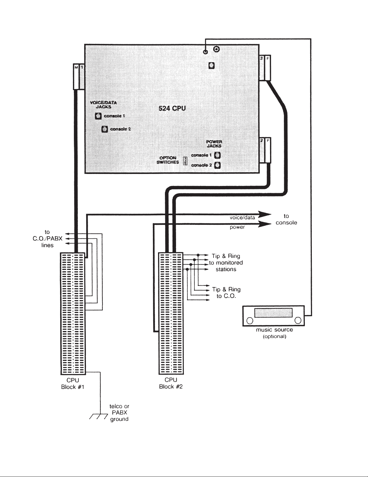
Refer to Figure 5.
1. Fasten a plywood sheet to the wall with hardware suitable for the wall material.
2. Using the supplied mounting template, mark and pre-drill the mounting holes for the CPU.
Make sure that the CPU mounting location is within 5 feet of a standard 117 VAC, 60 Hz grounded
power outlet.
Allow at least one foot of free space above and below the CPU for ventilation.
3. Drive in four suitable fasteners (such as #10×¾" pan head tapping screws), leaving the heads out ¼".
4. Remove the two cover screws, turn each CPU cover fastener so that the slots are horizontal, then
remove the cover.
When installation and testing are completed, replace the cover, turn each cover fastener so that
the slots are vertical, then lock it in place with the cover screws to assure compliance with UL
requirements. If the cover screws need to be replaced, use 6-32×¼" pan head machine screws.
5. Hang the CPU on the four mounting screws and tighten the screws.
6. Label each side of the split terminal blocks as shown in the Designation columns of Tables 1 and 2.
7. Mount the blocks to the plywood sheet below the CPU, using suitable fasteners.
Cabling to Blocks
Refer to Figure 5.
1. Punch down the cables to the blocks as shown in the Wire Color columns of Tables 1 and 2. The cable
with the male connector should be punched down to the right side of block #1.
2. Plug the 25 pair cable from block #1 into the connector on the left side of the CPU circuit board.
3. Plug the cable from the left side of block #2 into the connector on the lower right side of the CPU circuit
board.
4. Plug the cable from the right side of block #2 into the connector on the upper right side of the CPU
circuit board.
5. Secure the cables with the supplied cable retainers.
13-102408 Rev. H Page 13
Page 14
Tone Commander 524 Installation Instructions
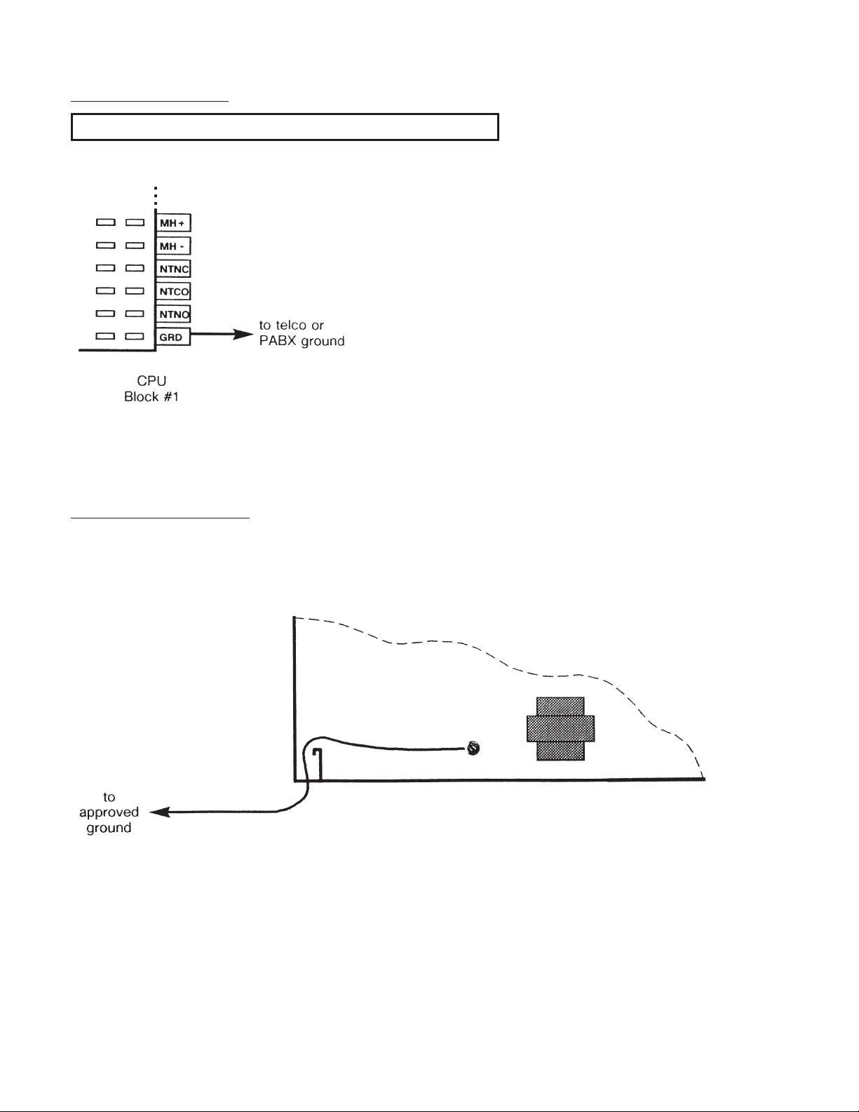
Reference Grounding
Reference grounding of the 524 is necessary for proper operation.
Connect telco or PABX ground to the GRD pin on the
bottom right of CPU block #1.
DO NOT connect this reference ground to the CPU's
metal housing!
Figure 1
CPU Chassis Grounding
This ground connection is required for safety and EMI shielding. It is usually provided by the 3rd wire on
the CPU power cord. If the integrity of the power outlet ground is questionable, use the ground connection
shown below for the 524 CPU.
Figure 2
1. Connect a solid copper #10 or #12 AWG wire to the ground terminal on the CPU. The wire should be
tightly clamped between the ground screw and the cup washer.
2. Connect the wire to an approved ground, such as MGN (multi-grounded neutral) from the power lines,
building ground, a metallic cold water pipe, or a grounding rod.
Page 14 13-102408 Rev. H
Page 15
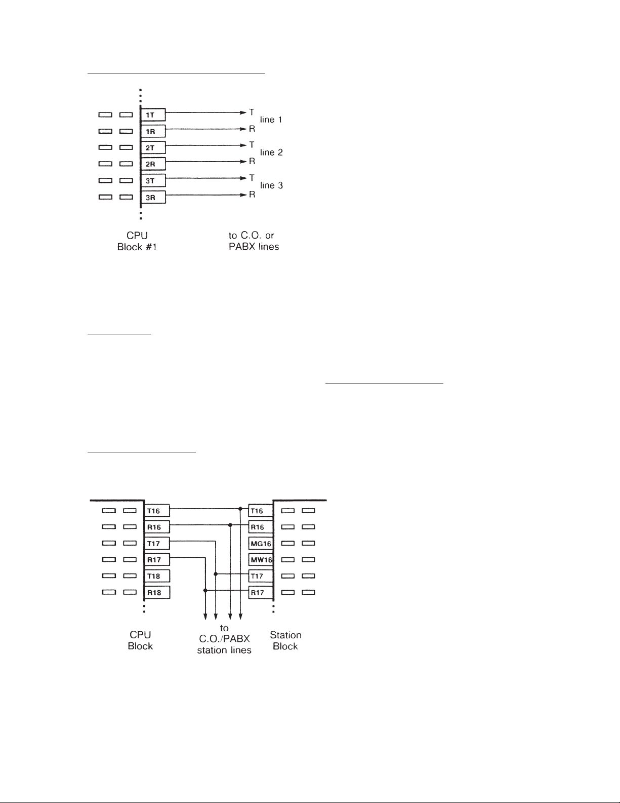
Connections to Telco/PABX Lines
Figure 3
Tone Commander 524 Installation Instructions
1. Connect Tip and Ring of each line to the associated
T and R pair on the right side of CPU block #1.
If the 524 is used with a key system, connect to the
C.O. side of the line cards.
2. If this installation has stations paralleled with console
lines, the stations should be connected to Tip and
Ring at the telco/PABX block.
Line Testing
Connect a test telephone to each line; verify the presence of dial tone, and break dial tone by dialing a
number.
The 524 allows DTMF tone dialing only – refer to the Telco/PABX Requirements
Test any additional features ordered with the lines. Open circuit voltage must be approximately 48 volts.
section.
Station Connections
Station Monitoring
Connect T (Tip) and R (Ring) from each
monitored station to the associated T and R
pins on CPU block #2. The 524 is connected
in parallel with the station lines.
Figure 4
13-102408 Rev. H Page 15
Page 16
Tone Commander 524 Installation Instructions
Figure 5
Page 16 13-102408 Rev. H
Page 17
Tone Commander 524 Installation Instructions
CONNECTOR #1
PIN NO.
26·······WHT-BLU······· – ··········1TN
1·······BLU-WHT······· – ··········1RN
27·······WHT-ORN ······· – ··········1C1
2·······ORN-WHT ······· – ··········1C2
28·······WHT-GRN ······· – ··········1C3
3·······GRN-WHT ······· – ··········1C4
29·······WHT-BRN ······· – ··········2TN
4·······BRN-WHT ······· – ··········2RN
30·······WHT-SLT ······· – ··········2C1
5·······SLT-WHT ······· – ··········2C2
31·······RED-BLU······· – ··········2C3
6·······BLU-RED ······· – ··········2C4
32·······RED-ORN ······· – ··········1T
7·······ORN-RED ······· – ··········1R
33·······RED-GRN ······· – ··········2T
8·······GRN-RED ······· – ··········2R
34·······RED-BRN ······· – ··········3T
9·······BRN-RED ······· – ··········3R
35·······RED-SLT ······· – ··········4T
10·······SLT-RED········ – ··········4R
WIRE COLOR (left side of block unused) DESIGNATION (right)
console #1
voice/data
console #2
voice/data
telco/PABX
lines
36·······BLK-BLU········ – ··········5T
11·······BLU-BLK ······· – ··········5R
37·······BLK-ORN ······· – ·········· –
12·······ORN-BLK ······· – ·········· –
38·······BLK-GRN ······· – ·········· –
13·······GRN-BLK ······· – ·········· –
39·······BLK-BRN ······· – ·········· –
14·······BRN-BLK ······· – ·········· –
40·······BLK-SLT········ – ·········· –
15·······SLT-BLK ········ – ·········· –
41·······YEL-BLU········ – ·········· –
16·······BLU-YEL········ – ·········· –
42·······YEL-ORN ······· – ·········· –
17·······ORN-YEL ······· – ·········· –
43·······YEL-GRN ······· – ·········· –
18·······GRN-YEL ······· – ·········· –
44·······YEL-BRN ······· – ·········· –
19·······BRN-YEL ······· – ·········· –
45·······YEL-SLT········ – ·········· –
20·······SLT-YEL········ – ·········· –
46·······VIO-BLU········ – ·········· –
21·······BLU-VIO········ – ·········· –
47·······VIO-ORN ······· – ·········· –
22·······ORN-VIO ······· – ·········· –
48·······VIO-GRN ······· – ··········MH+
23·······GRN-VIO ······· – ··········MH49·······VIO-BRN ······· – ·········· –
24·······BRN-VIO········ – ·········· –
50·······VIO-SLT········ – ·········· –
25·······SLT-VIO········ – ··········GRD
Table 1
CPU Block #1
Pinout
music input
telco ground
13-102408 Rev. H Page 17
Page 18
Tone Commander 524 Installation Instructions
CONNECTOR #2 CONNECTOR #3
PIN NO.
26·······WHT-BLU·······T1···········T16
1·······BLU-WHT·······R1···········R16
27·······WHT-ORN ·······T2···········T17
2·······ORN-WHT ·······R2···········R17
28·······WHT-GRN ·······T3···········T18
3·······GRN-WHT ·······R3···········R18
29·······WHT-BRN ·······T4···········T19
4·······BRN-WHT ·······R4···········R19
30·······WHT-SLT ·······T5···········T20
5·······SLT-WHT ·······R5···········R20
31·······RED-BLU·······T6···········T21
6·······BLU-RED ·······R6···········R21
32·······RED-ORN ·······T7···········T22
7·······ORN-RED ·······R7···········R22
33·······RED-GRN ·······T8···········T23
8·······GRN-RED ·······R8···········R23
34·······RED-BRN ·······T9···········T24
9·······BRN-RED ·······R9···········R24
35·······RED-SLT ·······T10 ·········· –
10·······SLT-RED········R10·········· –
WIRE COLOR DESIGNATION (left) DESIGNATION (right)
station
monitor
circuits
36·······BLK-BLU········T11 ·········· –
11·······BLU-BLK ·······R11 ·········· –
37·······BLK-ORN ·······T12 ·········· –
12·······ORN-BLK ·······R12·········· –
38·······BLK-GRN ·······T13 ·········· –
13·······GRN-BLK ·······R13·········· –
39·······BLK-BRN ·······T14 ·········· –
14·······BRN-BLK ·······R14·········· –
40·······BLK-SLT········T15 ·········· –
15·······SLT-BLK ········R15·········· –
41·······YEL-BLU········ – ·········· –
16·······BLU-YEL········ – ·········· –
42·······YEL-ORN ·······1C+·········· –
17·······ORN-YEL ·······1C- ·········· –
43·······YEL-GRN ·······1C+·········· –
18·······GRN-YEL ·······1C- ·········· –
44·······YEL-BRN ·······1C+·········· –
19·······BRN-YEL ·······1C- ·········· –
45·······YEL-SLT········ – ·········· –
20·······SLT-YEL········ – ·········· –
46·······VIO-BLU········2C+·········· –
21·······BLU-VIO········2C- ·········· –
47·······VIO-ORN ·······2C+·········· –
22·······ORN-VIO ·······2C- ·········· –
48·······VIO-GRN ·······2C+·········· –
23·······GRN-VIO ·······2C- ·········· –
49·······VIO-BRN ······· – ·········· –
24·······BRN-VIO········ – ·········· –
50·······VIO-SLT········ – ·········· –
25·······SLT-VIO········ – ·········· –
Table 2
CPU Block #2
Pinout
console #1
power
console #2
power
Page 18 13-102408 Rev. H
Page 19
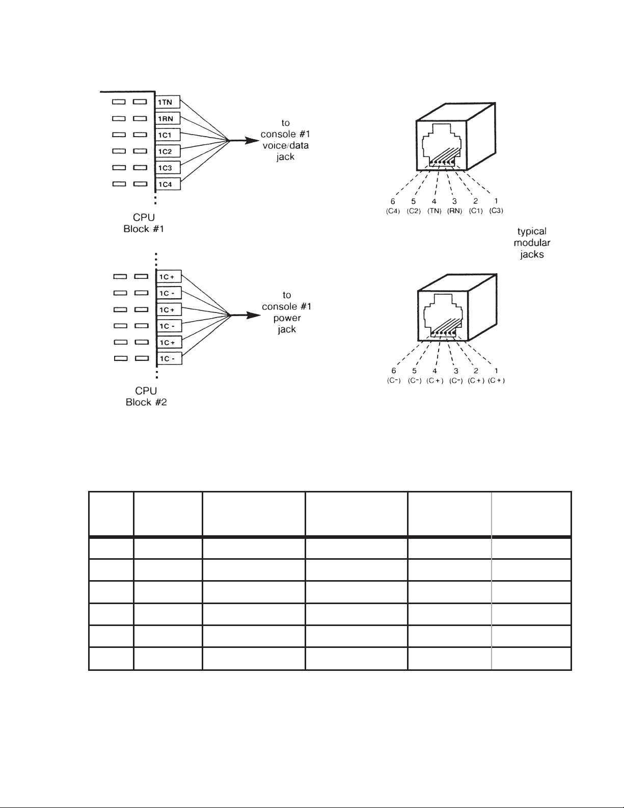
Console Cable Installation
Tone Commander 524 Installation Instructions
Figure 6
Wall
Jack
Pinout
1 WHT 1C3 (WHT-GRN) 2C3 (RED-BLU) WHT-GRN
2 BLK 1C1 (WHT-ORN) 2C1 (WHT-SLT) WHT-ORN
3 RED 1RN (BLU-WHT) 2RN (BRN-WHT) BLU-WHT
4 GRN 1TN (WHT-BLU) 2TN (WHT-BRN) WHT-BLU
5 YEL 1C2 (ORN-WHT) 2C2 (SLT-WHT) ORN-WHT
6 BLU 1C4 (GRN-WHT) 2C4 (BLU-RED) GRN-WHT
Wall Jack
Typical
Wire Color
Console #1
Designation
(connector 1)
Console #2
Designation
(connector 1)
Typical 3 Pair
Console Cable
Wire Color
Table 3 – Console “Voice/Data” Jack Pinout
(actual
wire color)
13-102408 Rev. H Page 19
Page 20

Tone Commander 524 Installation Instructions
Wall
Jack
Pinout
1 WHT 1C+ (YEL-BRN) 2C+ (VIO-GRN) WHT-GRN
2 BLK 1C+ (YEL-GRN) 2C+ (VIO-ORN) WHT-ORN
3 RED 1C- (ORN-YEL) 2C- (BLU-VIO) BLU-WHT
4 GRN 1C+ (YEL-ORN) 2C+ (VIO-BLU) WHT-BLU
5 YEL 1C- (GRN-YEL) 2C- (ORN-VIO) ORN-WHT
6 BLU 1C- (BRN-YEL) 2C- (GRN-VIO) GRN-WHT
Wall Jack
Typical
Wire Color
Console #1
Designation
(connector 1)
Console #2
Designation
(connector 1)
Typical 3 Pair
Console Cable
Wire Color
(actual
wire color)
Table 4 – Console “Power” Jack Pinout
The total console cable length, including line cord and equipment room cross connects, must not exceed
500 feet.
1. Install two 6 position, 6 contact modular telephone jacks within 6 feet of the console.
2. Label the jacks "524 voice/data" and "524 power".
3. Connect a 3 pair cable to each jack and run them to the equipment room.
IMPORTANT – Whenever nonkey adapters are used in conjunction with existing multipair cable, verify
that the adapters conform to Tables 3 and 4 above.
4. Only if the colors of your cables differ from the typical colors: fill out Tables 3 and 4 with the actual wire
colors of the cables for each connection.
5. Punch down the "voice/data" cable on the right side of CPU block #1, to the pins listed in the Console
#1 Designation column in Table 3.
6. Punch down the "power" cable on the left side of CPU block #2, to the pins listed in the Console #1
Designation column in Table 4.
7. If the system has two consoles (two attendant positions), punch down the second console's cables to
the pins listed in the Console #2 Designation columns of Tables 3 and 4.
Page 20 13-102408 Rev. H
Page 21

Console Installation
(bottom view)
Tone Commander 524 Installation Instructions
1. Install the handset cradle on the console
using the screws provided. The cradle may
be installed on either side of the console.
2. Plug the handset's cable into the jack
beneath the front left edge of the console.
3. Plug one end of each supplied 6 conductor
modular line cord into the "voice/data" and
"power" jacks at the back of the console.
If either line cord must be replaced, be sure
to use one with 6 conductors. Many line
cords with 6 position plugs have only 4
conductors.
4. Plug the cables into their associated wall
jacks, or into the test jacks located on the
CPU main circuit board (refer to Figure 5).
CAUTION – Do not interchange these two
cables! The cable nearest the
handset jack must connect to
the "voice/data" wall jack or
CPU jack.
5. Fill out the keycap labels with line numbers,
station names or numbers, and autodial
numbers (refer to the configuration sheets).
Place the labels beneath the clear plastic key
caps, then snap the keycaps onto the DSS
and line keys.
Figure 7
Preliminary Testing
At this time, you should have completed the following:
·
Mounted the CPU and blocks
·
Installed the cables from the CPU to the blocks
·
Connected Tip and Ring from each line to the block
·
Connected Tip and Ring from each monitored station to the block
·
Installed the console cables and jacks
·
Assembled and connected the console(s)
It is a good idea to briefly test the operation of the 524 before proceeding with installation or programming.
1. Plug the CPU into a power outlet.
A. The "heartbeat" indicator at the bottom of the CPU main circuit board should flash.
If no "heartbeat" is present, check that the power outlet is "live". A blown fuse on the circuit
board may indicate a defective CPU.
13-102408 Rev. H Page 21
Page 22

Tone Commander 524 Installation Instructions
B.The console should emit two triple beeps, then briefly display "524 OK".
If these indications are not observed, check both voice/data and power cabling.
2. Repeat step 1 at attendant position #2, if the system is so equipped.
C.O. Line Testing
Perform the following tests on each telco/PABX line. Repeat at attendant position #2, if the system is so
equipped.
Line Access and Imbalance Testing
1. Press the key representing the line to be tested.
The associated line lamp (telephone symbol) should flicker while the line is accessed.
NOTE – Open circuit voltage must be approximately 48 volts.
2. Listen for audible hum or excessive noise.
PAS S – Such noise or hum is not present.
FAILURE – Such noise or hum is present.
3. Listen for dial tone.
PAS S – Dial tone is heard.
FAILURE – Dial tone is not heard.
4. Break dial tone by dialing a digit.
PAS S - Dial tone is broken and no audible hum or excessive noise is heard.
FAILURE - Dial tone cannot be broken; audible hum or excessive noise is heard.
5. Press the RELEASE key.
IMPORTANT – Upon the detection of any failure during the foregoing testing, disconnect the affected
equipment from the telephone line to determine if such equipment is the cause of
failure. Any equipment determined to be malfunctioning must remain disconnected, and
use discontinued until the malfunction has been corrected.
Hold and Autohold Testing
1. Access the line to be tested and establish call to another station.
2. Place the call on hold by depressing the red HOLD key.
The associated Hindicator will wink slowly.
3. Reseize the call by depressing the line key.
The associated H indicator goes out.
The line lamp flickers while the line is accessed.
4. Place the call on autohold by depressing another idle line key.
The line accessed draws dial tone.
The line under test goes to autohold.
5. Release the line drawing dial tone and reseize, then release the line under test.
Page 22 13-102408 Rev. H
Page 23

Tone Commander 524 Installation Instructions
Ring Trip and Imbalance Testing
1. Dial the number of the line to be tested from another station.
The associated line lamp will flash slowly.
or
The associated line lamp will flash quickly, if the line has been optioned for ring delay.
2. Press the line key to answer the call.
The line lamp changes from flashing to flickering.
3. Listen for audible hum or excessive noise.
PAS S – Such noise or hum is not present.
FAILURE – Such noise or hum is present.
IMPORTANT – Upon detection of audible hum or excessive noise, disconnect the affected equipment,
to determine if such equipment is the cause of failure. Any equipment determined to be
malfunctioning must remain disconnected, and use discontinued until the malfunction
has been corrected.
4. Press the RELEASE key.
CPU Option Switches
Switches on the CPU control system programming options. The switches are ON when set towards the
right side of the CPU. When a programming option is "locked", programming changes are not allowed. The
switch location is shown in the figure below and on page 16.
Figure 8 – CPU Option Switches and Fuses
13-102408 Rev. H Page 23
Page 24

Tone Commander 524 Installation Instructions
SWITCH FUNCTION
1
2
3
4 not used
5 must be OFF!
6, 7 not used
8
OFF – Autodial Program unlocked
ON – Autodial Program locked
OFF – Configuration Program unlocked
ON – Configuration Program locked
OFF – Name Program unlocked
ON – Name Program locked
OFF – retain new programming
ON – restore defaults
(when power is cycled off & on)
Table5–CPUOption Switches
Optional Equipment Installation
The following options require system programming for proper operation. Refer to the Configuration
Programming section.
Music On Hold
An external music source is required for Music On Hold. It will be assigned to the lines during configuration
programming. The music input may be connected to any type of compatible music source (refer to the
Specifications
The music source can be connected to the jack provided on the CPU, or punched down to the block.
Jack Connections
section).
1. Connect an RCA-type phono plug to one end
of a single conductor shielded cable, or
obtain a cable with a plug attached. The
center conductor connects to the pin of the
plug.
2. Plug the cable into the music input jack at the
top of the CPU.
3. Connect the other end of the cable to the
output of the music source. A plug to fit the
music source may be required.
Figure 9
Page 24 13-102408 Rev. H
Page 25

Block Connections
Tone Commander 524 Installation Instructions
1. Connect a twisted wire pair to MH+ and MH-
on the right side of CPU block #1.
2. Connect the other end of the wire pair to the
output of the music source. A plug to fit the
music source may be required.
Figure 10
Paging
Tone Commander's PA-24 Paging/Chime module interfaces the 524 console to a paging system. The
module includes a night ringing chime, and switching for background music control. Power is derived from
the 524 CPU.
Paging can be connected to any spare line key on the 524. Refer to the PA-24 Paging/Chime Module
Installation Instructions, doc. #13-102595.
13-102408 Rev. H Page 25
Page 26

Tone Commander 524 Installation Instructions
Configuration Programming
Various network interface and operation parameters are programmable by the installer, allowing
compatibility with a wide variety of central offices and PABXs. The system is pre-programmed at the
factory; many installations will require few changes to these values. Programming is retained in the CPU's
memory when power is disconnected.
Systems with two attendant positions require programming at both consoles for recall rings and line privacy.
The programming procedures for ring delays, the time of day clock, autodial numbers, and station names
are described in their respective sections.
The following features may be set from configuration programming mode by pressing the appropriate DSS
key. The letters are printed on the console front panel beneath the DSS keys. Key numbers in parentheses
represent the station ports assigned to the keys.
System Programmable Features
DSS Key
A (1) Abandoned Ring Time
B (5) Recall Rings
C (9) Pickup Code Sequence
D (13) Dialing Speed
E (17) Pause Time
F (21) Hookflash Time
G (2) Dial Tone Detect Time
H (6) Hold Recall Time
I (10) Hold Release Time
* K (18) Queue Priority
L (22) Alert Type
* M (3) Ringing Type
R (23) Assign Page Key
Line Programmable Features
* O (11) Line Privacy
* P (15) Answer Use
Q (19) Assign Music On Hold to lines
Feature
* Features marked with an asterisk have separate settings for each console position in a two-position
system. They must be programmed individually at each console.
Page 26 13-102408 Rev. H
Page 27

Tone Commander 524 Installation Instructions
Using Configuration Programming Mode
The configuration programming mode must be entered prior to attempting any of the following
programming procedures. Enter this mode only when the console is idle, i.e., no calls are in progress or on
hold and the time of day is displayed.
The Configuration Program Lock Switch (switch #2) inside the CPU must be OFF (unlocked) before
proceeding (see page 23).
To enter configuration programming mode:
Press HOLD.
·
Press TRANSFER.
·
Press RELEASE.
·
Press dial pad key C (2).
·
The display will indicate that configuration programming mode has been entered.
To exit configuration programming mode and store all programming:
Press RELEASE.
·
or
The mode will be exited automatically 1 minute after the last keypress.
When completed, set the Configuration Program Lock Switch inside the CPU to ON (locked) to prevent
inadvertent changes to the programmed settings.
DSS keys on the console are used to select the feature to be programmed – letters identifying the keys are
printed beneath the keys on the console's front panel.
Default Settings
The default settings, as shipped from the factory, are listed with each feature on the following pages.
Default settings may be recalled by setting CPU option switch #8 to ON, then cycling the CPU power off
and on (pull out the power plug for a few seconds). Set this switch back to OFF to prevent losing your
programming during a power outage.
The switch location is shown on page 23.
Confirmation and Error Tones
The speaker in the console signals correct or incorrect actions during programming. The console's volume
control adjusts the level of the tones – use the VOL keys above the dial pad.
Confirmation Tone – double beep Error Tone – single beep
13-102408 Rev. H Page 27
Page 28
Tone Commander 524 Installation Instructions
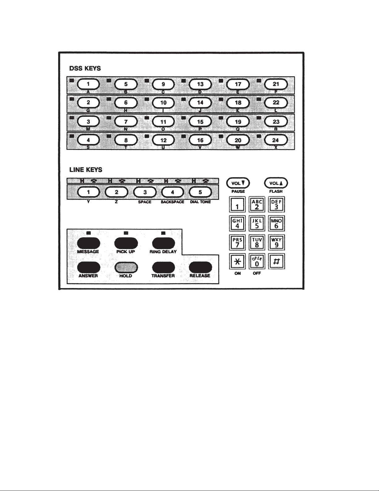
Figure 11 – 524 Console Keys
Page 28 13-102408 Rev. H
Page 29

Tone Commander 524 Installation Instructions
Programming System-Wide Features
Timing Parameters
Press HOLD, then TRANSFER, then RELEASE, then C (2) on the dial pad to enter configuration
·
programming mode.
"CONFIGURE PROG" will be displayed.
Press a DSS key to select the feature to be programmed.
·
The display will show the item name and the current value.
The station status lamp will light steadily.
Press a key on the dial pad if you want to change the value.
·
The new value will be shown in the display.
Press a DSS key to select another feature.
·
or
Press RELEASE to exit configuration programming mode (the mode will be exited automatically 1 minute
after the last keypress).
NOTE – Systems with two consoles (two attendant positions) have separate Queue Priority and Ringing
Type settings for each console. They must be programmed individually at each console position.
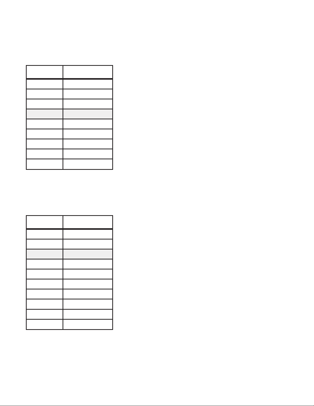
For example, to set Hold Recall Time to 50 seconds:
Figure 12
13-102408 Rev. H Page 29
Page 30
Tone Commander 524 Installation Instructions
Timing values listed in the following tables are nominal, and may differ slightly from the actual values.
Shaded values are factory defaults.
Abandoned Ring Time
Dial Pad Key Available Values
2 2 sec
3 3 sec
4 4 sec
5 5 sec
6 6 sec
7 7 sec
8 8 sec
9 9 sec
0 10 sec
Table 6
Recall Rings
DSS key to select feature: A
Default value: 5 sec
This parameter determines the timing for discontinuing ringing
of unanswered incoming calls that were abandoned by the
caller. It should be set to the next time value longer than the
silent interval between ringing bursts.
if too short – each ring burst may be seen as a new call. This
can cause erratic line lamp rates and loss of ringing delays.
if too long – abandoned calls will continue to ring for the
duration of this timing value.
Dial Pad Key Available Values
1 1 ring
2 2 rings
3 3 rings
4 4 rings
5 5 rings
6 6 rings
7 7 rings
8 8 rings
9 9 rings
0 no recall
Table 7
DSS key to select feature: B
Default value: 3 rings
This sets the number of rings before a call transferred to an idle
station recalls the console.
Set this parameter according to customer preference.
Page 30 13-102408 Rev. H
Page 31
Pickup Code Sequence
Tone Commander 524 Installation Instructions
Dial Pad Key Available Values
0
1
first
(before station #)
last
(after station #)
Table 8
Dialing Speed
Dial Pad Key Available Values
6
0
slow
(6 digits/sec)
fast
(10 digits/sec)
Table 9
DSS key to select feature: C
Default value: first
This parameter determines when the console inserts the
Directed Call Pickup code during a station call pickup dialing
sequence, as required by the telephone system.
Almost all installations require the pickup code to be first.
DSS key to select feature: D
Default value: fast
The tone autodialing speed (via DSS key) is set with this
parameter.
Use the dialing speed compatible with the central office or
PABX. If misdialing occurs with the fast speed, switch to slow
speed.
Pause Time
Dial Pad Key Available Values
2 200 ms
3 300 ms
4 400 ms
5 500 ms
6 600 ms
7 700 ms
8 800 ms
Manual dialing speed is also affected. When fast speed is
selected, manually dialed digits follow dial pad keystrokes. With
slow speed selected, digits are buffered and sent with a tone on
period of 80 ms, and 80 ms between digits. This guarantees
minimum tone periods for slow central offices.
DSS key to select feature: E
Default value: 700 ms
This sets the length of a "pause" in an autodial sequence.
Pauses are typically used to insert a delay in a dialing string
when calling voice mail or similar equipment. Change this
parameter if a delay other than a multiple of 700 ms is required.
For example, for a dialing delay of 2 seconds, set the pause
time to 500 ms and insert 4 pauses in the autodial sequence.
9 900 ms
Table 10
13-102408 Rev. H Page 31
Page 32

Tone Commander 524 Installation Instructions
Hookflash Time
Dial Pad Key Available Values
5 500 ms
6 600 ms
7 700 ms
8 800 ms
9 900 ms
0 1 sec
Table 11
Dial Tone Detect Time
Dial Pad Key Available Values
1 500 ms
DSS key to select feature: F
Default value: 600 ms
This parameter sets the length of a timed hookflash generated
during call transfer and autodial operations. The default value is
adequate for most systems.
if too short – receipt of second dial tone may be intermittent
during call transfer operations.
if too long – the calling party may be disconnected during call
transfer operations.
DSS key to select feature: G
Default value: 700 ms
2 600 ms
3 700 ms
4 1 sec
5 1.2 sec
6 1.5 sec
7 1.8 sec
8 2 sec
Table 12
This sets the time steady dial tone must be present before
station digits are autodialed.
Set this parameter to the lowest value that gives reliable dial
tone detection.
Page 32 13-102408 Rev. H
Page 33

Hold Recall Time
Tone Commander 524 Installation Instructions
Dial Pad Key Available Values
3 30 sec
4 40 sec
5 50 sec
6 60 sec
9 90 sec
1 2 min
2 3 min
0 no recall
Table 13
Hold Release Time
Dial Pad Key Available Values
140ms
DSS key to select feature: H
Default value: 90 sec
Calls on console hold longer than the Hold Recall Time will
recall the console.
Set this parameter according to customer preference.
NOTE – Calls on hold at the telephone system (initiated by a
hookflash) will not recall the console.
DSS key to select feature: I
Default value: 600 ms
280ms
3 200 ms
4 400 ms
5 600 ms
6 800 ms
7 1 sec
8 2 sec
A central office disconnect supervision signal (i.e., brief battery
removal) on any line must exceed this value. When such a
signal from a line on hold is detected, the line will be
automatically released.
Set this parameter to a value slightly less than the length of a
disconnect signal from the central office.
if too short – may cause calls on hold to be inadvertently
disconnected.
if too long – may cause abandoned calls and retrieved parked
calls to remain connected to the console.
Table 14
13-102408 Rev. H Page 33
Page 34

Tone Commander 524 Installation Instructions
Queue Priority
Dial Pad Key Available Values
1 stations only
2 stations, then lines
3 lines, then stations
4 FIFO
Table 15
Alert Type
DSS key to select feature: K (per console)
Default value: FIFO
Calls are queued for attendant processing in the order received.
The first call in queue is shown in the display.
Queue Priority determines which type of calls have priority in
the queue:
(1) stations only
(2) lines+stations, stations have priority
(3) lines+stations, lines have priority
(4) lines+stations, first calls have priority
(FIFO, First In - First Out)
Set this parameter according to customer preference. FIFO is
recommended for most installations.
NOTE – The call queue is cleared whenever Queue Priority is
changed.
Dial Pad Key Available Values
1 normal ringing
2 distinctive ringing
0 both
Table 16
Ringing Type
Dial Pad Key Available Values
1 long
0 short
Table 17
DSS key to select feature: L
Default value: both
To ignore station-to-station calls, equip the station lines with
distinctive ringing from the C.O. Set the Alert Type to distinctive
if distinctive ringing is provided for outside calls, or to normal if
distinctive ringing is provided for station-to-station calls.
DSS key to select feature: M (per console)
Default value: short
This parameter determines the type of audible ringing: short (1
beep), or long (3 beeps), when unanswered station calls are
showing in the display.
Set this parameter according to customer preference.
Page 34 13-102408 Rev. H
Page 35

Tone Commander 524 Installation Instructions
Special Feature Key Assignment
Spare line keys may be programmed to activate special features. Such usage precludes the connection of
lines to these positions. Be sure to identify the keys with the supplied key cap labels.
Press HOLD, then TRANSFER, then RELEASE, then C (2) on the dial pad to enter configuration
·
programming mode.
"CONFIGURE PROG" will be displayed.
Press the DSS key to select the feature to be programmed:
·
R – Page key
Press dial pad key
·
The line lamp (phone symbol) above a line key will be on if the key has the feature assigned to it.
Press the line key that will be assigned the feature.
·
The line lamp above the selected key will light steadily. Any feature assignment for the key will be
overwritten.
The previously assigned key will be cleared (reassigned as a standard line key); its line lamp will
turn off.
or
Press the currently assigned key to clear its programming and reassign it as a standard line key, if no
keys are to be assigned the selected feature.
The line lamp above the selected key will turn off.
NOTE – Perform a line test (at both consoles, if applicable) if a key has been reassigned as a
standard line key – refer to the Preliminary Testing
· Press dial pad key 0 to store the new setting and return to feature selection.
· Press a DSS key to select another feature.
or
Press RELEASE to exit configuration programming mode (the mode will be exited automatically 1
minute after last keypress).
to display the key that is set to activate the desired feature.
*
section in this document.
13-102408 Rev. H Page 35
Page 36

Tone Commander 524 Installation Instructions
Programming Features Selectable Per Line
The following programmable features do not apply to line keys that have been programmed for Page.
Press HOLD, then TRANSFER, then RELEASE, then C (2) on the dial pad to enter configuration
·
programming mode.
"CONFIGURE PROG" will be displayed.
Press a DSS key to select the feature to be programmed.
·
The display will show the item name.
The station status lamp will light steadily.
Press the line key to be programmed with the selected feature.
·
The display will show the line number and the current value (OFF or ON).
The line lamp (phone symbol) will light steadily.
Press ON (
·
The new value will be shown in the display.
Press another line key to be programmed with the selected feature.
·
Press RELEASE to exit configuration programming mode (the mode will be exited automatically 1
minute after last keypress).
)orOFF (0) on the dial pad if you want to change the value.
*
or
NOTE – Systems with two consoles (two attendant positions) have separate Line Privacy and Answer Use
settings for each console. They must be programmed individually at each console position.
Line Privacy
DSS key to select feature: O (per console)
Default Value for each line: off
A line with the privacy option on cannot be accessed by the console when its line lamp indicates a "busy"
condition.
Answer Use
DSS key to select feature: P (per console)
Default Value for each line: off
Idle lines in this group will automatically be seized in descending order whenever the ANSWER key is used
to pick up station calls.
CAUTION – Lines assigned to this group must be optioned for Directed Call Pickup, NonBarge-In.
Dedicated nonhunting lines are recommended for this usage. If this is not feasible, assign only
the last line in a terminal hunt group.
Page 36 13-102408 Rev. H
Page 37

Tone Commander 524 Installation Instructions
Music On Hold
DSS key to select feature: Q
Default Value for each line: on
This selects whether the external music source will be connected to a line that is on hold at the console
(hard hold, not
Centrex hold).
13-102408 Rev. H Page 37
Page 38

Tone Commander 524 Installation Instructions
DSS/Autodial Number Programming
Each DSS key may be programmed to autodial up to 24 digits or functions, including 0-9,*, #, dial tone
detect, a hookflash (transfer signal), and a pause. The PICK UP key autodials the call pickup code; it must
be also programmed with the required digits.
Digits are entered with the dial pad. The VOL keys and DSS key #5 are used to enter the pause, flash, and
dial tone detect functions – these functions are printed below the keys on the console front panel.
DIAL TONE delays dialing until steady dial tone is present. If the telephone system does not send dial
tone after receiving a flash, use two PAUSEs in place of DIAL TONE detect.
FLASH is used to transfer calls or access special features of the telephone system.
PAUSE is used if a delay is required during dialing, for example to access a voice mailbox.
Pause, flash, and dial tone detect times can be changed from the 524 configuration programming mode.
IMPORTANT – The first entry of a dialing routine for any key to be used for DSS operation must be a
FLASH (F). This entry will determine whether associated features with DSS operation will
apply (Station Recall or Ring Delays).
Example: FD4710
Dialing routines, where the first entry is not a FLASH, will operate as Autodialing keys.
Example: D9D5551982
Programming Procedure
Set the Autodial Program Lock Switch (switch #1) inside the CPU to OFF (unlocked) before proceeding –
see page 23.
· Press HOLD, then TRANSFER, then RELEASE, then P (7) on the dial pad to enter autodial
programming mode.
"PROGRAM AUTODIAL" will be displayed.
·
Press the DSS key to be programmed.
The station status lamp will light.
The display will show the number currently programmed, or "NOT PROGRAMMED".
·
If you do not wish to change the currently programmed number, press HOLD, then select another
DSS key.
·
Using the dial pad and the PAUSE, FLASH, and DIAL TONE keys, enter the sequence to be dialed.
The display will show the number being entered.
·
Press HOLD to store the number, then select another DSS key to be programmed.
or
Press RELEASE to store the number and exit autodial programming mode (the mode will be exited
automatically 1 minute after the last keypress, without storing the number).
When completed, set the Autodial Program Lock Switch inside the CPU to ON (locked) to prevent
inadvertent changes to autodial programming.
NOTE – Systems with two consoles (two attendant positions) have a single set of DSS/autodial numbers
shared by both consoles. The numbers may be programmed at either console.
Page 38 13-102408 Rev. H
Page 39

Tone Commander 524 Installation Instructions
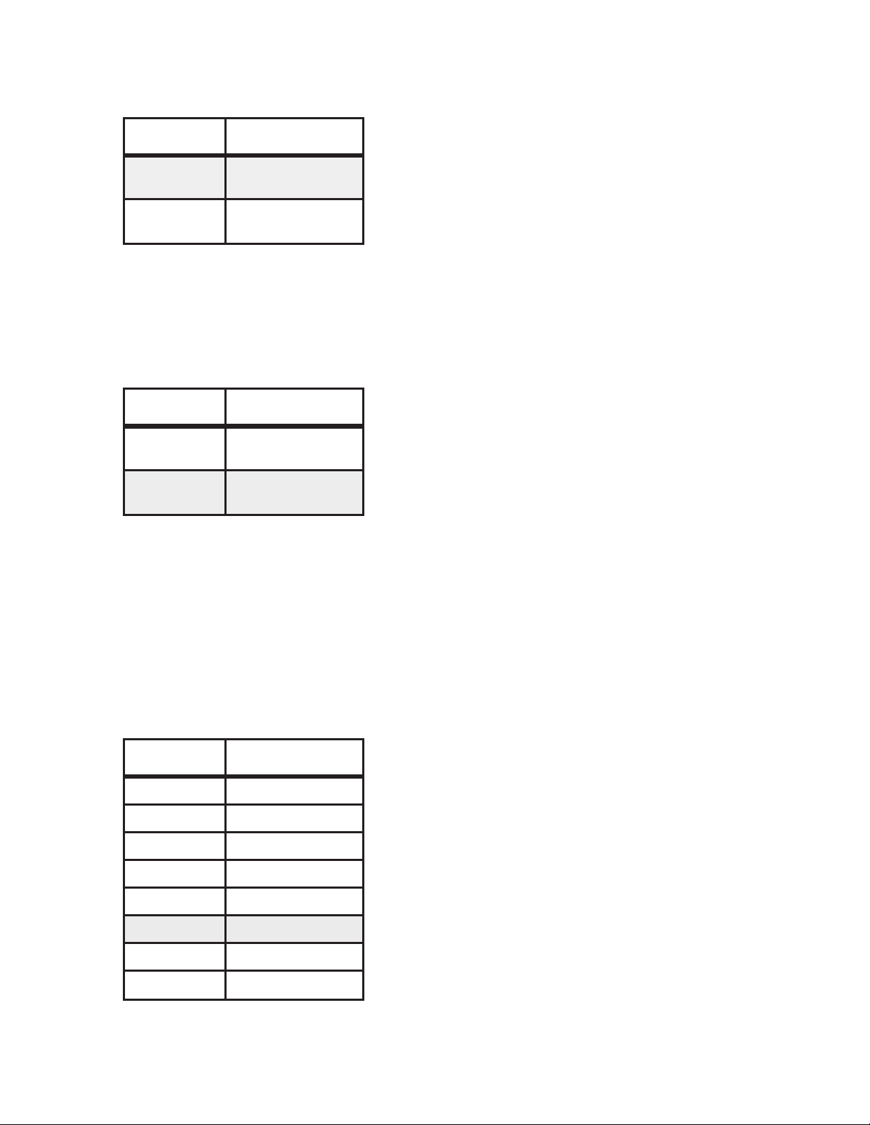
For example, to program a DSS key to dial a hookflash, wait for dial tone, then dial station 5314:
Figure 13
Pick Up Key Programming
The PICK UP key programming procedure is similar to that for DSS keys. Press PICK UP instead of
selecting a DSS key, then proceed as illustrated below. Consult the telco for the required pickup code.
IMPORTANT – A DIAL TONE detect must be entered before the Directed Call Pickup code to ensure that
steady dial tone is received before dialing begins. This may not apply to the few telephone
systems which require the Directed Call Pickup code to be dialed after the station number.
DO NOT precede the pickup code with a FLASH.
For example, to program the PICK UP key with the code
7:
*
Figure 14
13-102408 Rev. H Page 39
Page 40

Tone Commander 524 Installation Instructions
Name Display Programming
Any DSS/Autodial key to be programmed with a name display must already be programmed for autodialing;
autodial programming may be changed without reprogramming the DSS name display. This restriction does
not apply to line keys, since they cannot be programmed for autodialing.
Set the Name Program Lock Switch (switch #3) inside the CPU to OFF (unlocked) before proceeding – see
page 23.
Press HOLD, then TRANSFER, then RELEASE, then N (6) on the dial pad to enter name
·
programming mode.
"NAME ASSIGN" will be displayed, followed by a help display.
Press the DSS or line key to be programmed.
·
The lamp next to the selected key will light steadily.
The name will be displayed if the selected key is currently programmed. Press CLEAR to allow
reprogramming, or use BACKSPACE to edit the currently programmed name.
If you do not wish to change the currently programmed name, press HOLD, then select another DSS
·
or line key.
Enter the name using the DSS and line keys. Letters are printed on the console front panel beneath
·
the keys. Do not exceed 14 characters, including spaces. BKSPACE will delete the last character
entered.
· Press HOLD to store the new name.
· Select another DSS or line key to be programmed.
or
Press RELEASE to exit name identification programming mode (the mode will be exited automatically
1 minute after the last keypress).
When completed, set the Name Program Lock Switch inside the CPU to ON (locked) to prevent inadvertent
changes to name programming.
NOTE – Systems with two attendant console positions have a single set of DSS/autodial name displays
shared by both positions. The names may be programmed at either console position.
Page 40 13-102408 Rev. H
Page 41

Tone Commander 524 Installation Instructions
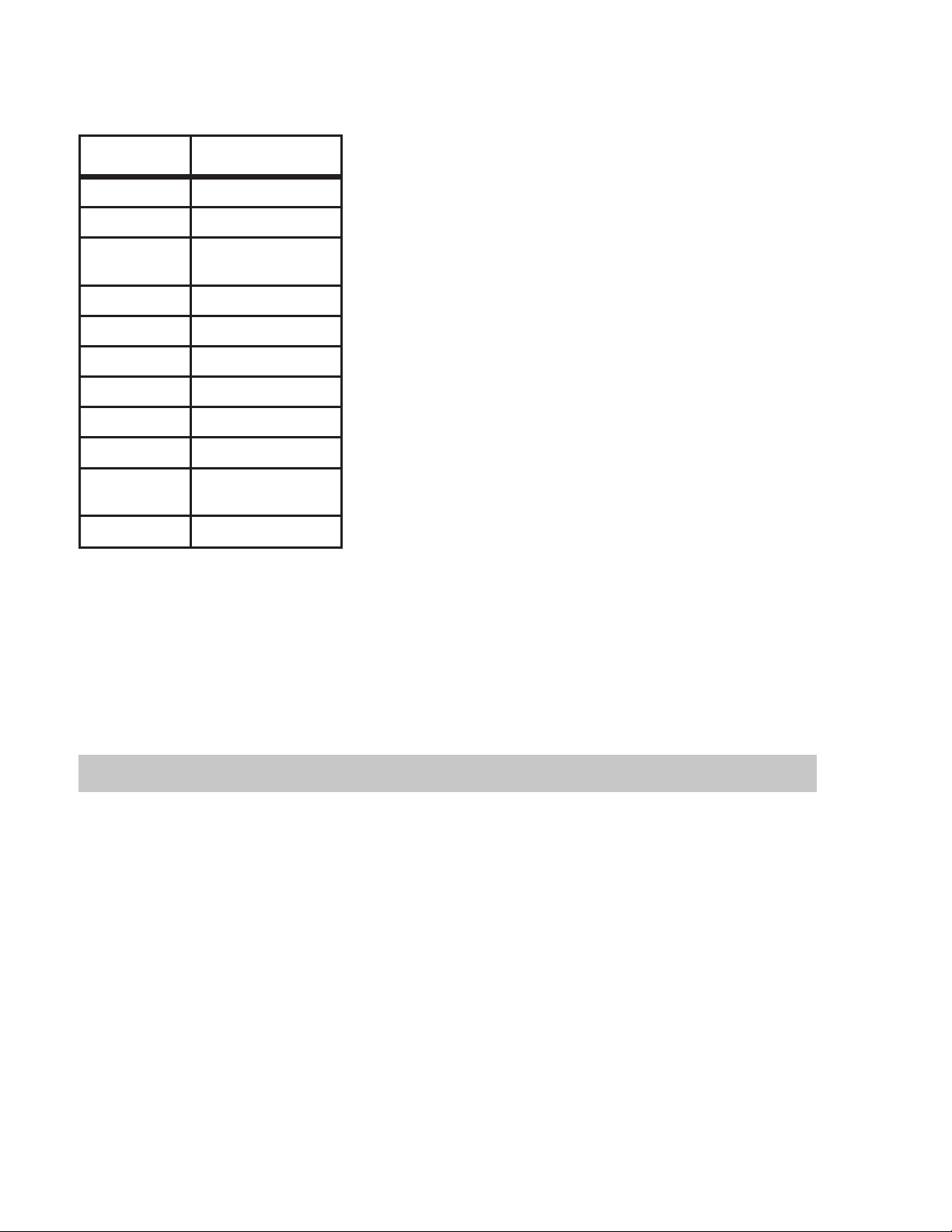
For example, to program the name "Smith" to be displayed when station #4 is ringing:
Figure 15
Ring Delay Programming
Checking Ring Delays
·
Press RING DELAY twice.
The lamp above the key will flash, and "RING DELAY CHECK" will be displayed.
·
Press the DSS or line keys to be checked.
The display will show the ring delay setting for each DSS or line key pressed.
·
To exit ring delay check mode, press RING DELAY again (the mode will be exited automatically 5
seconds after the last keypress).
13-102408 Rev. H Page 41
Page 42
Tone Commander 524 Installation Instructions
Setting Ring Delays
Press RING DELAY once.
Dial Pad Key Available Values
1 1 ring
2 2 rings
3
4 4 rings
5 5 rings
6 6 rings
7 7 rings
8 8 rings
9 9 rings
0
*
3 rings
stations default
no delay (off)
lines default
no ringing (on)
·
The lamp above the key will light steadily, and “RING
DELAY PROG” will be displayed.
Using the dial pad, enter the number of rings to delay before
·
ringing at the console begins (1-9 rings, 0 for no delay, or
for no ringing at the console).
The display will show the selected ring delay value.
NOTE – The ring delay setting does not affect station
Press the DSS or line keys to be set to the chosen ring delay
·
value.
To set all stations (not lines) to the same value, press # on
the dial pad instead of a DSS key.
The display will show the number of each DSS or line
key that is pressed (or “ALL DELAY” if # is pressed), and
the ring delay value.
To exit ring delay set mode, press RING DELAY again (the
·
mode will be exited automatically 5 seconds after the last
keypress).
*
ringing, only the delay before the console starts
ringing in addition to the station.
Table 18
NOTE – Systems with two consoles (two attendant positions) have separate Ring Delay settings for each
console. They must be programmed individually at each console.
Time of Day Clock
The 12-hour time of day clock may be set at either console in a two-position system. The setting affects
both consoles.
·
When the console is idle, press HOLD, then TRANSFER, then RELEASE, then T (8) on the dial pad.
"SET TIME" and the current time will be displayed.
·
Press RELEASE now if you do not wish to change the time setting.
·
Enter the time using the dial pad (hour values less than 10 must be preceded by a "0" digit). For
example, to set the time to 9:38, enter 0938.
The display will show the time entered.
·
The time set mode will be exited automatically after the new time setting is entered.
Page 42 13-102408 Rev. H
Page 43

Tone Commander 524 Installation Instructions
System Description
Consoles
The 524consoles house a 20-character fluorescent display, line status indicators, line and call processing
keys, a common audible transducer, an electronic voice network, and a microcomputer to control their
operation. The factory-provided hearing aid compatible handset utilizes an electret (carbon clone) element.
Tone Commander consoles are designed to provide superior operating capabilities in any working
environment.
The vacuum fluorescent display is adjustable, can be seen from almost any angle, and is immune to
·
overhead lighting glare. This allows displayed information to be viewed from greater distances than
with nonfluorescent versions.
Whenever possible, call processing routines are accomplished with single keystrokes.
·
Multiple indicators are used to improve status recognition.
·
Following is a description of the keys, indicators, and connectors on the console:
Display – 20 character alphanumeric display gives information about calls ringing at the console, and
·
is used during console programming. A time of day clock is displayed when the console is idle.
· Line Keys – when a line key is pressed, the console network is connected to the selected line. If a
second line key is pressed, the first line is automatically put on hold and the second line is accessed
(Auto Hold). Spare line keys may be used to access paging systems.
· Hold Lamps (H symbol) – indicate hold and hold recall states of the lines.
· Line Lamps (telephone symbol) – indicate busy and ringing states of the lines.
· DSS Keys – when the console is in normal mode, the 24 DSS keys automatically dial programmable
sequences when pressed. These keys are also used during programming to enter name displays.
They are normally used to autodial the station associated with the key.
· Station Status Lamps – indicate busy and ringing states for the stations.
·
HOLD Key – when the console is on an active line and the hold key is pressed, a hold bridge is
placed across the selected line and the console network is released from the connection.
·
TRANSFER Key – when the transfer key is pressed, a hookflash (momentary open loop) is
generated on the selected line. This allows the attendant to transfer calls or access special features
of the telephone system.
·
RELEASE Key – when the console is on a line and the release key is pressed, the console network
is released from the connection, the line becomes idle, and its lamp will turn off.
·
ANSWER Key – automatically seizes a call appearing in the alphanumeric display.
·
RING DELAY Key – used to enter/exit ring delay check mode or ring delay programming mode.
·
PICK UP Key – used to answer a ringing station not appearing in the alphanumeric display.
·
VOL Keys – used to adjust the console ringer volume.
·
Dial Pad – generates DTMF signaling on a selected line. Dial pad keys are also used to enter
console programming values.
Attendant Console Cabling
Three pair, #24 gauge, twisted cable is required. The two cable runs should not exceed 500 feet each. One
pair on the voice/data cable is analog voice. The two remaining pairs transmit proprietary protocol at 1200
baud using the RS-422 standard.
13-102408 Rev. H Page 43
Page 44

Tone Commander 524 Installation Instructions
The second cable uses all three pairs to provide power to the console.
Central Processing Unit (CPU)
The Central Processing Unit is a wall mounted device which contains the power supply,
microprocessor-based control logic, 5 line circuits, 24 station circuits, dial tone detect circuits, two console
data link circuits, two DTMF dialer circuits, and a Music On Hold input circuit. System memory is retained
during power failure.
External connections to the Central Processing Unit are made by using 50 pin Amphenol connectors. Music
on hold may be optionally connected to an RCA-type audio jack on the CPU. Modular console jacks on the
main circuit board are provided for testing and programming.
System Features
Dual Console Capability
The CPU can support two console positions. Line and station appearances are identical at each console
(square line configuration). Holding status is indicated at both console positions. Special line key options
(paging access) appear at both console positions when programmed. Certain operating features such as
Queue Priority, Ringing Type, Line Privacy, and Answer Use may be programmed on per console basis.
Skinny Wire Console Connection
Six pair cabling is required between each console and the CPU. Three pair are used for data and voice,
and three pair are used for power. Two 6 conductor modular jacks are located at the rear of the console,
one for voice/data and one for power.
Installer/User Programmability
Both installer and user can program the system from the front panel of the console. The installer programs
system configuration options, line programmable features, and special feature key assignments. The user
can program customized features such as ring delays, Direct Station Selection (DSS) dialing, autodialing
numbers, line/station name identification, Hold Recall Time, Queue Priority, etc.
Ringing Queue
Calls to be answered by a console are placed in queue. The nature of the queue (i.e. station calls only,
stations before lines, lines before station, or first in-first out "FIFO") is selectable on a per console basis.
Distinctive Ringing Detection
Used in conjunction with the Distinctive Ringing capability provided by the serving Centrex C.O. or PABX,
unanswered station calls can be displayed alphanumerically or ignored, depending on the type of ringing.
Paging Interface
The Tone Commander PA-24 Paging/Chime Module or an equivalent external, battery-feed paging adapter
can be connected to any line key programmed as a Page key. When this is done, the selected line position
will be conditioned to operate with either 48 VDC or 24 VDC battery feed circuits, the latter being typical of
most paging adapters. The PA-24 can be powered directly from the 524 CPU.
Page 44 13-102408 Rev. H
Page 45

Tone Commander 524 Installation Instructions
Music On Hold Interface
Each line can be set to provide audio programming while in a holding state. Access is via block terminals or
phono jack. An input gain control is provided to adjust programming to the desired level.
Console Test Jacks
Six pin modular jacks for both voice/data and power are provided for two console positions. These jacks
are intended to provide a quick means to verify console-to-CPU operating integrity.
Console Features
Distinctive Audible Signaling
The system recognizes normal or distinctive ringing from the serving central office/PABX and responds with
differentiated audible signaling. The console also signals the attendant when held lines are recalling, calls
to stations have gone unanswered for a predetermined period of time, confirming programming
entries/storage, or when errors have been made involving operation or programming. Incoming call audible
signaling is abbreviated whenever the attendant is active on a line.
Ring Delay
Each line and station appearing on a console can be individually programmed to ring at the console
immediately, after a predetermined number of ringing cycles, or never ring at the console. The Ring Delay
feature does not affect ringing at the station.
Alphanumeric Display
Calls to be answered are displayed with a three character prefix which indicates the nature of the call (i.e.
INC, RCL, HLD, CMP, etc.), followed by the line or station number, then the number of calls in queue. Line
or station numbers can be replaced with 14 character names as desired. The display is also used to view
programming options and confirm all entries.
Single-key Answering
Calls to lines or stations that are to be answered by the attendant are alphanumerically displayed according
to the selected ringing queue. Depressing the Answer key seizes the call displayed.
Dial Pad DTMF Dialing
The 524 console is equipped with a standard 12 button dial pad. The various tones will persist as long as
the desired key is pressed if fast dialing speed (10 digits/sec.) has been selected during configuration
programming. If slow speed (6 digits/sec.) has been selected, digits are buffered and sent with a tone on
period of 80 ms, and 80ms between digits to guarantee minimum tone periods for slow central offices.
Time of Day
The alphanumeric display shows the time of day whenever the console is idle.
Variable Ringer Volume
VOL6and VOL5keys are provided on the face of the console to adjust the level of the audible ringer in
accordance with the operating environment. A bar graph display is provided for referencing.
13-102408 Rev. H Page 45
Page 46

Tone Commander 524 Installation Instructions
Handset Jack Connection
A four pin modular jack is located on the left side of the console.
Handset
A K-type, hearing aid compatible handset with electret transmitter is provided with the console.
Direct Line Access
Each line is accessible via a dedicated key for answering, holding, transferring and originating calls.
I-Use Indication
A fluttering line status lamp identifies the particular line to which the handset or headset is connected.
Line Privacy
Individual lines may be programmed to exclude third party access to ongoing calls by the attendant.
Line Hold
Each line can be placed in a "Hard Hold" condition at the console. Music on Hold, if optioned and a source
provided, is connected to the line. A line on "Hard Hold" can be released from the console when bridged by
either a telephone set or another console. A valid loop interruption from the central office will also release
the line.
Line Hold Indication
A flashing Line Hold lamp H indicates a line placed on hold by the attendant. A steady H indication
identifies a line placed on hold at the companion console.
Automatic Line Hold
Active lines may automatically be placed on "Hard Hold" by either depressing another line key or the
Answer key while a call is being displayed.
Hold Recall
A call placed on Hold for longer than a predetermined time period is identified with a unique audible ringing.
The H indication for the affected line is also unique.
Line Transfer
Calls originating or answered at the console can be placed in a "Soft Hold" or Consultation Hold condition
at the serving Centrex Central Office/PABX by "hookflashing" (pressing the transfer key), then dialing the
desired station number.
Page Key (optional)
Any line key can be programmed to be a Page key. When this is done, the selected key position is
automatically assigned line privacy, answer use exclusion, and automatic line hold exclusion.
Pressing the Page key places the currently selected line on hold and connects the attendant to the paging
system.
Page 46 13-102408 Rev. H
Page 47

Tone Commander 524 Installation Instructions
Autodialing
Any spare DSS key can be used for autodialing while on an active line.
Busy Lamp Field (BLF)
Each station connected to the "console system" has a dedicated lamp that indicates its status (i.e. idle,
off-hook, or ringing).
Direct Station Selection (DSS)
DSS keys provide quick and efficient transfer of all calls. Each key position must be programmed with the
appropriate dialing instructions - typically a Flash, Dial Tone Detect, then the station digits. The DSS feature
is available only for stations that are monitored by the 524.
Station Recalls
Calls transferred by a DSS key to idle stations which go unanswered for a predetermined period, re-ring
and are displayed at the console.
Station Call Pickup
Unanswered calls that are indicated in the busy lamp field but not in the alphanumeric display can be
answered at any time by depressing the Pickup key, then the desired DSS key.
Telco/PABX Requirements
Certain signaling protocols and features of the telco/PABX host are required for proper operation.
Required System Configuration
The C.O. and station lines must originate from either the same Centrex Common Block or the same PABX
tenant partition.
Required Signaling Protocols
1. -42.5 to -56.5 VDC C.O. battery
2. 40 to 130 Vrms @ 20 or 30 Hz Ring Generator
3. Loop start
4. Disconnect Supervision for Abandoned Calls
The central office opens Tip and Ring (removes the source of DC voltage) for a brief interval whenever the
calling party disconnects prior to the called party. This protocol is required to support automatic hold
release.
Required Attendant Line Features
1. Touch Tone Dialing – all manual or auto dialing from the 524 console is DTMF.
2. Station Call Transfer – to use the Transfer key or the programmable FLASH command while
autodialing to transfer incoming calls. Typically, inbound calls are transferred by "hookflashing",
receiving new dial tone, then dialing the desired station. In most instances call transferring is limited to
stations within the same PABX or Centrex Common Block.
13-102408 Rev. H Page 47
Page 48

Tone Commander 524 Installation Instructions
CAUTION – In some host systems, hookflashing automatically transfers inbound calls to a proprietary
attendant position. This feature is often referred to as Call Transfer-Attendant and is not
compatible with Tone Commander console operation.
3. Directed Call Pickup, NonBarge-In – to retrieve unanswered station calls showing in the alphanumeric
display.
Optional Line Features
Dedicated nonhunting attendant lines – used to retrieve unanswered station calls. It is recommended
that (1) nonhunting line per console be provided for this purpose. This will allow dedicated access,
unaffected by inbound traffic, and prevent call collisions (glare). Refer to the Answer Use line feature
described on page 36.
Required Station Feature
Call Pickup – all station lines monitored by the 524 must be assigned to a Call Pickup Group.
IMPORTANT – Call Forward - No Answer is not recommended because it conflicts with, and may defeat,
the operation of the 524 Ring Delay and Name Display features.
Optional Station/Line Features
Additional features may be optioned as required.
IMPORTANT – Whenever the Call Waiting feature is invoked on a busy station, such a call will not recall to
the console. Ring Delay and Recall Ring parameters do not apply because the station in
question is in a busy rather than a ringing state.
Compatibility With Other Products
Music On Hold
The Music On Hold input on the 524 CPU is compatible with telco feed, low impedance, balanced
subscriber background music services such as Muzak. Always terminate such a line with a resistor equal to
the characteristic impedance of the line, usually 600 ohms. AM/FM tuner and tape player outputs are
typically unbalanced high impedance music sources which require shielded cable. Characteristic
impedances vary from 600 to 50K ohms.
Paging Access
The 524 is compatible with any paging system that provides a Tip/Ring talk battery feed circuit. Such
circuits can be cross connected to any spare line position on the console.
Tone Commander's PA-24 Paging/Chime Module interfaces any paging amplifier to the 524, and derives
power from the 524 CPU.
Voice Mail
Most on-premise voice mail systems are compatible with the 524 system. Voice mail is usually accessed
from a spare DSS key.
Page 48 13-102408 Rev. H
Page 49

Tone Commander 524 Installation Instructions
524 Specifications
All values listed in this section are nominal, and may differ from the actual values.
Central Office Interface
Line Capacity ..........5lines
Local Telco Ground and
CPU Ground Differential ....±3Vmax.
C.O. Battery Range .......-42.5 V to -56.5 V
C.O. Ringing Range ......40to130Vrms@20or30Hz,superimposed on C.O. battery
Off-hook/On-hook
Detection Point .........26Vacross Tip and Ring
Loop Resistance to C.O.,
Including C.O. Battery Feed . . 400 to 2000 ohms
FCC
Registration Number ......AHIUSA-60815-CF-T
Ringer Equivalence .......0.0A
Console Interface (CPU to Console)
Consoles ............oneortwo
Max. Distance to Console....500feet, using 24 AWG wire
Station Interface
Station Capacity ........24stations
Max. Distance to Stations....2000 feet, using 24 AWG wire
Dialer
Dialing Type...........DTMF Tone only
Autodialing Speed .......6or10digits/sec
Manual Dialing Speed .....follows dial pad keystrokes when autodialing speed is set to 10
digits/sec; digits are buffered and sent with a tone on period of
80 ms, and 80 ms between digits when autodialing speed is set
to 6 digits/sec
Music Input
Input Impedance ........10kohms, balanced
Typical Input Level .......0.5vto1.5vRMS
Gain Adjustment Range ....40dB
13-102408 Rev. H Page 49
Page 50

Tone Commander 524 Installation Instructions
Power Requirements
CPU...............117VAC±10%, 60 Hz, @ 30 VA max.
Console .............power supplied by CPU
Fuses
CPU...............(2)AGC2 2 A, 250 V
Physical
Console Dimensions ......6½"H,11¾"W,10½"D
(including handset cradle; display in max. vertical position)
Console Weight .........3lbs.
CPU Dimensions ........17¾"H,21½"W,4
CPU Weight...........12lbs.
Environmental
5
/16"D
Console
Operating Temperature .....32°to104° F (0° to 40° C)
CPU
Operating Temperature .....32°to122° F (0° to 50° C)
Console and CPU
Storage Temperature ......-4°to140° F (-20° to 60° C)
Humidity.............5%to95%, noncondensing
Installer Programmable Features
Abandoned Ring Time .....2-10sec
Recall Rings ..........1 - 9 rings, or no recall
Pickup Code Sequence .....first or last
Dialing Speed ..........6or10digits/sec
Pause Time ...........200-900msec
Hookflash Time .........500ms-1sec
Dial Tone Detect Time .....500ms-2sec
Hold Recall Time ........30sec - 3 min, or no recall
Hold Release Time .......40ms-2sec
Queue Priority..........stations only
lines+stations, stations have priority
lines+stations, lines have priority
lines+stations, first calls have priority
(selectable per console)
Distinctive Ringing Detect....onoroff
Ringing Type ..........long or short (selectable per console)
Line Privacy ...........onoroff(selectable per line and per console)
Answer Use ...........onoroff(selectable per line and per console)
Page 50 13-102408 Rev. H
Page 51

Tone Commander 524 Installation Instructions
Music on Hold..........onoroff(selectable per line)
Special Feature Keys ......Page (may be assigned to any spare line key)
Attendant Programmable Features
Ring Delays ...........1-9rings, no delay, or no ringing
(selectable per line and per station)
Autodial Numbers ........24digits (selectable per station)
Line Identification Display....14alphanumeric characters
(selectable per line and per station)
Programming Data Retention
Data Retention .........10years
13-102408 Rev. H Page 51
Page 52

Tone Commander 524 Installation Instructions
Maintenance
After initial installation, the 524 requires little or no maintenance, as long as adherence to the criteria
discussed in the Site Preparation
suggested:
DON'T allow stored items to accumulate around the CPU, and therefore cut off adequate ventilation.
DON'T store toxic or fume producing janitorial supplies or chemicals in the near vicinity of the CPU.
DON'T plug any other electrical products into the same circuit as the CPU, even temporarily.
DON'T allow storage items or tools to come in contact with the CPU or punchdown blocks. In case of the
latter, plastic block covers are highly recommended.
DON'T spray cleaners or solvents directly on to the 524 console. Use only a very dilute soap/water
solution applied to damp rag.
DON'T use adhesive-backed labels on the face of the console. Such labels may impede button travel.
Migrating adhesives could also cause permanent damage.
DO use the provided nonadhesive key designations.
section is maintained. In this effort the following guidelines are
DO conduct periodic inspections to check the above mentioned items.
DO provide for ready access.
Operational Checkout
It is a suggested operating practice for an attendant to periodically check all active lines on the 524 for the
ability to receive and "break" dial tone.
Recommended Spare Parts
On those occasions where components need to be replaced either due to troubleshooting procedure or
obvious failure (i.e., smoke, inactivity, etc.), the stocking of spare parts is highly recommended.
In most cases one (1) console and one (1) CPU will provide adequate backup.
In those cases where a customer demands full backup capability or has to maintain many systems, two (2)
consoles and two (2) CPUs are recommended. In this case, full coverage is maintained even when spares
are in for repair.
Page 52 13-102408 Rev. H
Page 53

Tone Commander 524 Installation Instructions
Service
Repair of the Tone Commander 524 must be done by Tone Commander. Prior to equipment removal, call
Tone Commander Technical Support for assistance in determining the source of the problem. This critical
action can often prevent needless removal of equipment and subsequent customer inconvenience.
Tone Commander
Technical Support Department
11609 49th Place West
Mukilteo, WA 98275-4255 USA
Phone: (800) 524-0024
(425) 349-1000
Fax: (425) 349-1010
E-mail: tech@tonecommander.com
Web: www.tonecommander.com
Tone Commander is committed to meeting the product needs of our customers. Please write or call us with
any suggestions for improvement.
Warranty
Tone Commander Product Warranty
For a period of one year from date of dealer purchase, but not to exceed 16 months from date of
manufacture, Tone Commander Systems, Inc. (Tone Commander) warrants its products to be free from
defects in material and workmanship under conditions of normal use and service. Tone Commander shall,
at its option, repair or replace any defective product which, in its opinion, has not been misused, damaged,
or improperly installed.
Repair or replacement under this warranty will be performed at Tone Commander's factory. Authorization
must be obtained from Tone Commander prior to returning a product for repair. Freight must be prepaid for
all units returned to Tone Commander. Units repaired under warranty will be shipped UPS Ground (or
equivalent), freight prepaid by Tone Commander.
Products that are older than the warranty period, but less than 7 years old, or still manufactured by Tone
Commander may be repaired at the factory for a flat rate charge. Repaired out-of-warranty units are
warranted for 90 days from the date of repair.
The repair or replacement of a product under this warranty represents the entire obligation of Tone
Commander; Tone Commander shall not be liable for any special or consequential damages resulting from
or caused by any defect, failure, incapacity or malfunction of any of its products.
The foregoing express warranty is in lieu of all other warranties, express or implied,
including but not limited to any implied warranty of merchantability, fitness, or adequacy for
any purpose or use, quality, productiveness or capacity; Tone Commander, to the extent
permitted by law, hereby disclaims all such other warranties.
13-102408 Rev. H Page 53
Page 54

Tone Commander 524 Installation Instructions
FCC Requirements
The Tone Commander Model 524 complies with Part 68 of the FCC Rules. The label affixed to this
equipment contains, among other information, the FCC Registration Number and Ringer Equivalence
Number (REN) for this equipment. You must, upon request, provide this information to your telephone
company.
The REN is useful to determine the quantity of devices you may connect to your telephone line and still
have all of those devices ring when your telephone number is called. In most, but not all areas, the sum of
the RENs of all devices connected to one line should not exceed five (5.0). To be certain of the number of
devices you may connect to your line, as determined by the REN, you should contact your local telephone
company to determine the maximum REN for your calling area.
The following jacks must be ordered from the telephone company in order to interconnect this product with
the public communication network: RJ-21X.
If your 524 causes harm to the telephone network, the Telephone Company may discontinue your service
temporarily. if possible, they will notify you in advance. But if advance notice is not practical you will be
notified as soon as possible. You will be informed of your right to file a complaint with the FCC.
Your telephone company may make changes in its facilities, equipment, operations or procedures that
could affect the proper functioning of your equipment. If they do, you will be notified in advance to give you
an opportunity to maintain uninterrupted telephone service.
Connections to party lines are subject to state tariffs. Contact your local telephone company if you plan to
use this equipment on party lines.
This equipment cannot be used on public coin service lines provided by the telephone company.
The 524 is hearing-aid compatible (HAC) per Section 68.316, FCC Rules and Regulations.
If you have trouble with the 524 please contact us at the address listed on the back of this manual for
information on obtaining service or repairs. The telephone company may ask that you disconnect the 524
from the network until the problem has been corrected or until you are sure that the equipment is not
malfunctioning.
NOTE – This equipment has been tested and found to comply with the limits for a Class A digital device,
pursuant to Part 15 of the FCC Rules. These limits are designed to provide reasonable protection
against harmful interference when the equipment is operated in a commercial environment. This
equipment generates, uses, and can radiate radio frequency energy and, if not installed and used
in accordance with the instruction manual, may cause harmful interference to radio
communications. Operation of this equipment in a residential area is likely to cause harmful
interference in which case the user will be required to correct the interference at his own expense.
Page 54 13-102408 Rev. H
Page 55

Tone Commander 524 Installation Instructions
Industry Canada Requirements
The Industry Canada label identifies certified equipment. The certification means that the equipment meets
certain telecommunications network protective, operational and safety requirements. Industry Canada does
not guarantee the equipment will operate to a user's satisfaction.
Before installing this equipment, make sure you are permitted to connect it to the facilities of the local
telecommunications company. You must also install the equipment using an acceptable method of
connection. In some cases you may also extend the company's inside wiring for single line individual
service by means of a certified connector assembly (telephone extension cord). You should be aware,
however, that compliance with the above conditions may not prevent degradation of service in some
situations.
Repairs to certified equipment should be made by an authorized Canadian maintenance facility designed
by the supplier. Any repairs or alterations made by a user to this equipment, or equipment malfunctions,
may give the telephone communications company cause to request the user to disconnect the equipment.
For your own protection, make sure that the electrical ground connections of the power utility, telephone
lines and internal metallic water pipe system, if present, are connected together. This precaution may be
particularly important in rural areas.
CAUTION: Do not attempt to make electrical ground connections yourself; contact the appropriate electric
inspection authority or electrician.
LOAD NUMBER: See the FCC label.
The load number (LN) assigned to each terminal device denotes the percentage of the total load to be
connected to the telephone loop used by the device, to prevent overloading. The termination on a loop may
consist of any combination of devices, subject to the requirement that the total of the load numbers of all
the devices not exceed 100.
Compliance Notice
This digital apparatus does not exceed the Class A limits for radio noise emissions for digital apparatus as
set out in the Radio Interference Regulations of Industry Canada.
Avis de conformation
Le present appareil numerique n'emet pas de bruits radioelectriques depassant les limites applicables aux
appareils numeriques de Ia class A prescrites dans le Reglement sur le brouillage radioelectriques edicte
par le ministere des Communications du Canada.
13-102408 Rev. H Page 55
Page 56

Tone Commander 524 Installation Instructions
Page 56 13-102408 Rev. H
Page 57

Tone Commander 524 Installation Instructions
524 Configuration Sheet
System Programmable Features
STATION
KEY
A
B
C
D
E
F
G
H
FEATURE
‘ABANDON’
Ring Time
‘RECALL’
Rings
‘DCP DIAL’
Sequence
‘DIAL SPEED’ 6, 0
‘PAUSE’ Time 2-9 200 - 900 msec 700
‘FLASH’ Time 5-9,0
Dial Tone
‘DETECT’
Time
‘HOLD’
Recall Time
DIAL PAD
KEYS
2-9,0
1-9,0
0, 1 first, last
1-9,
0
3-6,9,
1, 2, 0
AVAILABLE
VALUES
2 - 9 sec,
10 sec
1 - 9 rings,
no recall
slow (6 digits/sec),
fast (10 digits/sec)
500 - 900 msec,
1 sec
500, 600, 700 msec,
1, 1.2, 1.5, 1.8, 2 sec
30 - 60, 90 sec,
2, 3 min, no recall
DEFAULT
VALUE
5
3
first
(0)
fast
(0)
600
700
90
ACTUAL VALUE
Hold
I
K
‘RELEASE’
Time
Queue
‘PRIORITY’
1-8
1-4
L ‘ALERT TYPE’ 1, 2, 0
M
‘RNG TYPE’ 1, 0 long, short
DIRECTED CALL PICKUP CODE
45, 80, 200, 400, 600,
800 msec
1, 2 sec
stations only,
stations > lines,
lines > stations,
lines + stations (FIFO)
normal ringing,
distinctive ringing, both
600
FIFO
(4)
both
(0)
short
(0)
13-102408 Rev. H Page 57
Page 58

Tone Commander 524 Installation Instructions
524 Configuration Sheet
Line Programmable Features
(Default settings for all lines are shown in BOLD ITALICS.)
LINE
KEY
NO.
1
2
3
4
5
LINE NAME I.D.
or
PAGE KEY
PRIV.
WHEN
BUSY
O
O
F
F
N
MUSIC
ON
HOLD
O
O
F
N
F
ANS.
USE
O
F
F
O
N
RING
DELAY
(NO
RINGING,
NO
DELAY,
1-9
RINGS
TELEPHONE
NUMBERS
)
Page 58 13-102408 Rev. H
Page 59

Tone Commander 524 Installation Instructions
524 Configuration Sheet
DSS Keys
DSS keys are numbered vertically on the console.
DSS
KEY
1
2
3
4
5
6
7
8
9
10
STATION
NUMBER
USER NAME
DSS
KEY
13
14
15
16
17
18
19
20
21
22
STATION
NUMBER
USER NAME
11
12
23
24
13-102408 Rev. H Page 59
Page 60

Tone Commander 524 Installation Instructions
Page 60 13-102408 Rev. H
 Loading...