

Page 1
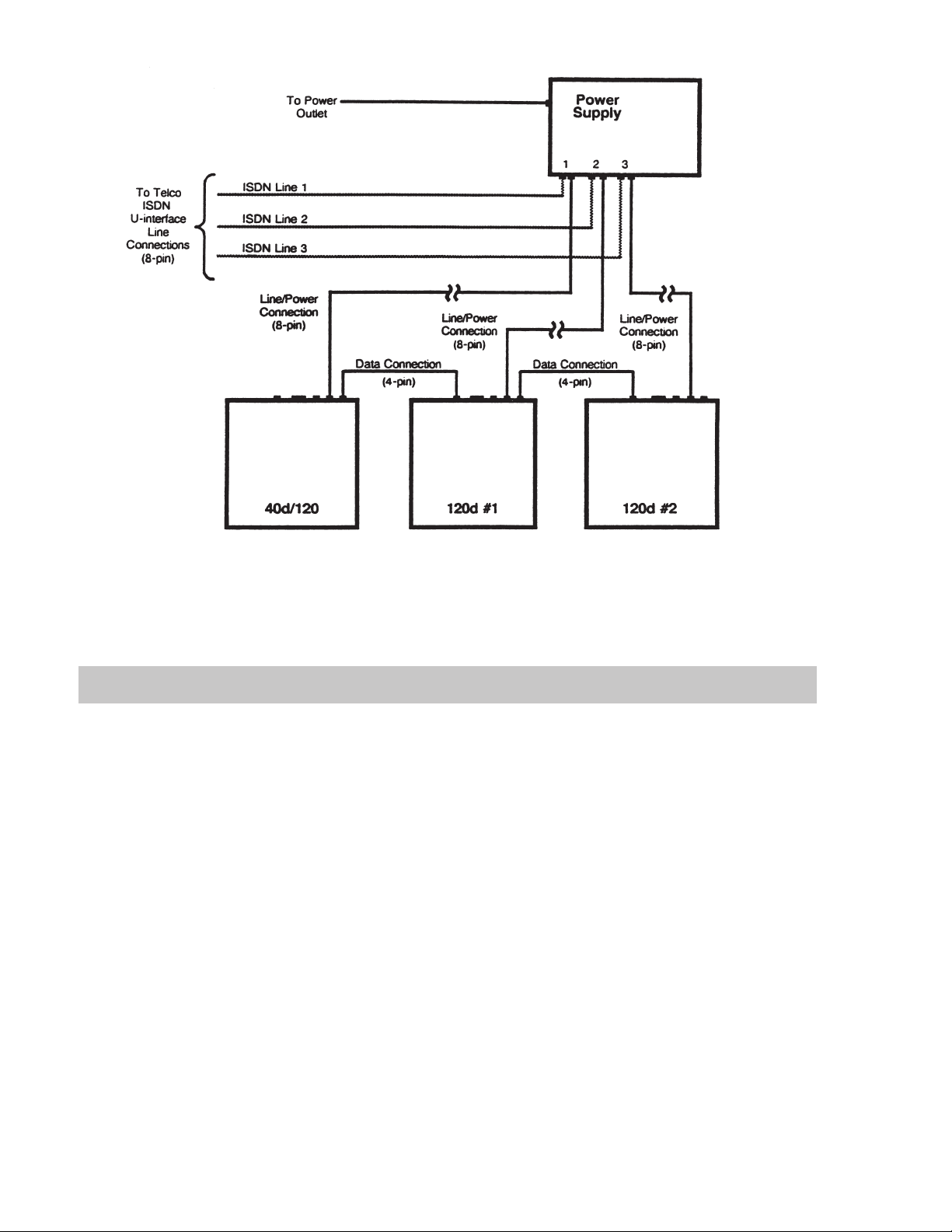
The 40d Power Supply is designed to be used
with 40d120 consoles. The Power Supply
provides power and an ISDN telco path to the
consoles. Each power supply supports a
maximum of one 40d console and two 120d
consoles.
Installation
40d120
Power Supply
Installation
Instructions
NOTE – All lines must be connected to the appropriate jacks as indicated on the power supply. Refer to the
40d120 Installation Instructions (doc. #13-102633) for specific installation procedures.
Location
The power supply may be mounted near the console or in a back equipment room. Maximum cable length
between the power supply and consoles is 500 feet.
Wall Mounting
1. Fasten a plywood sheet to the wall.
2. Mark and pre-drill the mounting holes for the power supply.
Make sure that the power supply is mounted within 5 feet of a standard 117 VAC, 60 Hz grounded
power outlet.
3. Mount the power supply using suitable fasteners (such as #10 x ¾” pan head tapping screws).
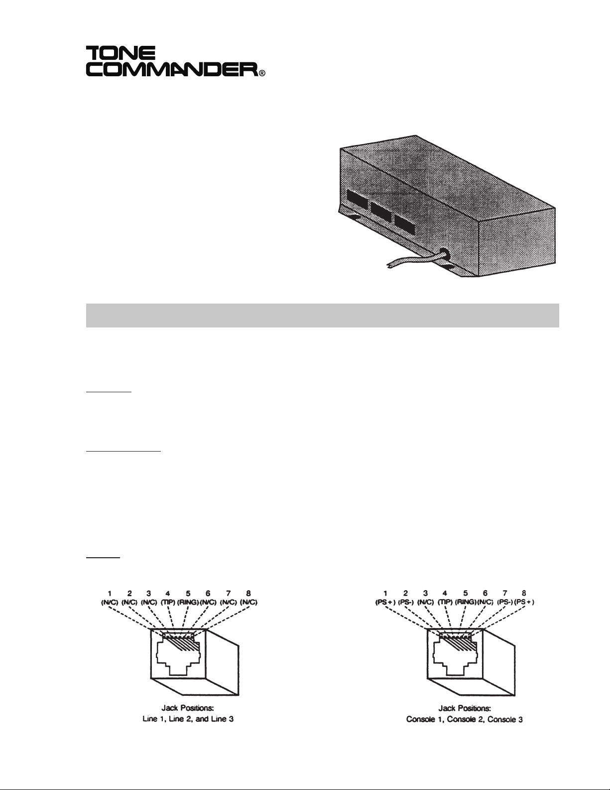
Wiring
All connecting cords and cables must be wiring. See the figure below for jack pinout.
13-102612 Rev. B
August 2000
Page 2
Tone Commander 40d120 Power Supply Installation Instructions
Specifications
Power Requirements ......110VAC, 60 Hz, @ 1 A max.
Power Output ..........38VDCnominal, 1.5 A max.
Physical Dimensions ......3"Hx8.5" W x 5" D
Weight .............5lbs. 2 oz.
Operating Temperature .....0°-50°C(32° - 122° F)
Humidity.............5%to95%, non-condensing
Standards Compliance .....UL/cUL 1459, component of 40d120 system
Page 2 13-102612 Rev. B
Page 3

Tone Commander 40d120 Power Supply Installation Instructions
Service
Repair of the 40d120 Power Supply must be done by Tone Commander. Prior to equipment removal, call
Tone Commander Customer Technical Support for assistance in determining the source of the problem.
This critical action can often prevent needless removal of equipment and subsequent customer
inconvenience.
Tone Commander
Customer Technical Support Department
11609 49th Place West
Mukilteo, WA 98275-4255 USA
Phone: (800) 524-0024
(425) 349-1000
Fax: (425) 349-1010
E-mail: tech@tonecommander.com
Web: www.tonecommander.com
Warranty
Tone Commander Product Warranty
For a period of one year from date of dealer purchase, but not to exceed 16 months from date of
manufacture, Tone Commander Systems, Inc. (Tone Commander) warrants its products to be free from
defects in material and workmanship under conditions of normal use and service. Tone Commander will, at
its option, repair or replace any defective product which, in its opinion, has not been misused, damaged, or
improperly installed.
Repair or replacement under this warranty will be performed at Tone Commander’s factory. Authorization
must be obtained from Tone Commander prior to returning a product for repair. Freight must be prepaid for
all units returned to Tone Commander. Units repaired under warranty will be return shipped UPS Brown
Label (or equivalent), freight prepaid by Tone Commander.
Products which are older than the warranty period, but less than 7 years old, or still manufactured by Tone
Commander, may be repaired at the factory for a flat rate charge. Repaired out-of-warranty units are
warranted for 90 days from the date of repair.
The repair or replacement of a product under this warranty represents the entire obligation of Tone
Commander; Tone Commander will not be liable for any special or consequential damages resulting from
or caused by any defect, failure, incapacity or malfunction of any of its products.
The foregoing express warranty is in lieu of all other warranties, express or implied, including
but not limited to any implied warranty of merchantability, fitness, or adequacy for any purpose
or use, quality, productiveness or capacity; Tone Commander, to the extent permitted by law,
hereby disclaims all such other warranties.
13-102612 Rev. B Page 3
Page 4

Tone Commander 40d120 Power Supply Installation Instructions
Page 4 13-102612 Rev. B
 Loading...