

Tomco DE89RB100-US, HP-200, HP-500, DE89RB- 1000, HP-1000 Operation & Maintenance Manual
...Page 1

CARBON DIOXIDE
DRY ICE PELLETIZER
OPERATION &
MAINTENANCE
MANUAL
Page 2

ii
Page 3

CARBON DIOXIDE
DRY ICE PELLETIZER
OPERATION & MAINTENANCE MANUAL
Copyright © 1998 by TOMCO2 EQUIPMENT COMPANY
All rights reserved. No part of this document
may be reproduced by any means without
the written permission of TOMCO
Revision 8– Add Ice behind piston problem to page 5.4
EQUIPMENT COMPANY.
2
January 14, 2003
TOMCO2 EQUIPMENT COMPANY
3340 Rosebud Road
Loganville, Georgia 30052 USA
Telephone
(770) 979-8000 • Toll Free in the U.S. (800) 832-4262
Fax
(770) 985-9179
Parts & Service Fax
(770) 979-2514
E-Mail
Internet
http://www.tomcoequipment.com
iii
Page 4

iv
Page 5

TABLE OF CONTENTS
Section 1 - Introduction ................................................................................... 1.0
Tomco2 Equipment Company Carbon Dioxide Dry Ice Pelletizers ......................... 1.1
Understanding Carbon Dioxide .............................................................................. 1.2
Learning More About Carbon Dioxide .................................................................... 1.5
Specifications ........................................................................................................ 1.7
Section 2 - Carbon Dioxide Safety .................................................................. 2.0
General Safety Considerations .............................................................................. 2.1
Rescue .................................................................................................................. 2.2
Inhalation First Aid ................................................................................................. 2.2
Exposure First Aid ................................................................................................. 2.2
Section 3 - Installation ..................................................................................... 3.0
Section 4 - Operation & Maintenance ............................................................. 4.0
Manual Operation ................................................................................................. 4.1
Automatic Operation .............................................................................................. 4.2
Maintenance .......................................................................................................... 4.4
Section 5 - Troubleshooting ............................................................................ 5.0
Section 6 - Repair & Adjustments ................................................................... 6.0
Section 7 - Appendix ........................................................................................ 7.0
Glossary ................................................................................................................ 7.1
References ............................................................................................................ 7.2
Warranty ................................................................................................................ 7.3
Replacement Parts & Ordering Information ........................................................... 7.4
Cus t omer Questionnaire ........................................................................................ 7.16
Drawings
v
Page 6

vi
Page 7

SECTION
1
INTRODUCTION
1.0
Page 8

INTRODUCTION
TOMCO2 EQUIPMENT COMPANY CARBON DIOXIDE DRY
ICE PELLETIZERS
Tomco2 has been a CO2 equipment specialist for over thirty years. Tomco2 manufactures Urethane Insulated CO
CO
ISO Containers, CO2 Particle Filters, CO2 Vaporizers, CO2 Pumps, CO2 Clean-
2
ing Systems, and CO
Tomco
offers a 24-hours a day, 365 days a year, Parts and Service Department. The
2
Water Treatment Systems.
2
Storage Units, Vacuum Insulated CO2 Storage Units,
2
telephone number is 800-832-4262 (toll free in the U.S.) or 770-979-8 000.
Our dry ice pelletizers are available in models capable of producing from 100
hour to 3000 lbs/hour of dry ice pellets. These units are made of the highest quality
lbs/
materials and workmanship.
Thank you for purchasing our CO
dry ice pelletizers, and if we can be of service to
2
you, please contact us.
1.1
Page 9

INTRODUCTION
UNDERSTANDING CARBON DIOXIDE
Carbon dioxide is a chemical compound formed by combining one atom of carbon
with two atoms of oxygen, and is expressed by the molecular formula CO
. Carbon
2
dioxide can exist in any one or all three states of matter: solid, liquid, and/or vapor;
depending on conditions of temperature and pressure.
Under normal atmospheric conditions, carbon dioxide exists as a colorless, odorless
gas which is about 1.5 times heavier than air. Carbon dioxide will not burn or
support combustion and will not sustain life.
When confined within a suitable pressure vessel, carbon dioxide can exist in any of
three states of matter depending on conditions of temperature and pressure. The
point at which all three states may exist in equilibrium is -69.9
o
F (-56.6 oC) and 60.4
psig (4.2 bar). This is called the triple point. At temperatures and pressures
lower than the triple point, carbon dioxide may be either a solid or a vapor, again
depending on conditions. Dry ice (solid carbon dioxide), at a temperature of -109.3
o
F (-78.5 oC) at atmospheric pressure, sublimes (transforms directly from solid into
vapor without the formation of a liquid).
o
The critical point of carbon dioxide is 87.9
At temperatures and pressures greater than 87.9
F (31.1 oC) and 1070.6 psig (73.8 bar).
o
F (31.1 oC) and 1070.6 psig (73.8
bar), carbon dioxide cannot exist as a liquid. At pressures and temperatures greater
than the critical point, carbon dioxide exist s onl y as a supercritical fluid.
At temperatures and pressures above the triple point and below the critical point,
carbon dioxide liquid with overlying vapor may exist in equilibrium within a closed
vessel. Within this range, there is a definite relationship between te mperature,
pressure, and density.
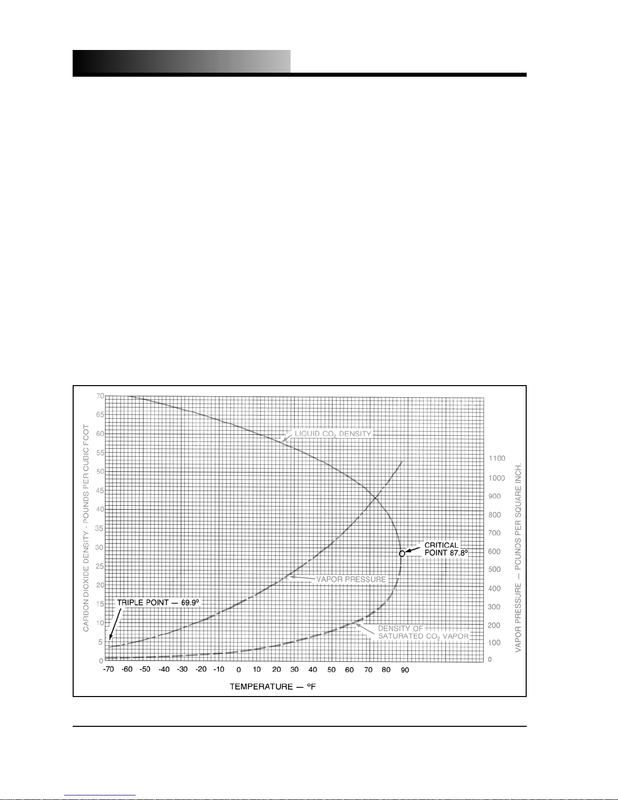
By following the vapor pressure curve in Figure 1.1 on page 1.3, it becomes obvious
o
that if you desire to store liquid carbon dioxide at 70
F (21.1 oC), the pressure vessel
would have to be bui lt to withs t and pressures of around 840 psig (57.9 bar). By
1.2
Page 10
INTRODUCTION
following the liquid dens ity curve, one finds that the liquid becomes less dense as the
temperature increases and at 70
per cubic foot (754 kg/m
3
).
By comparing the pressure and liquid density at 70
bar) and 47.6 pounds per cubic foot (764 kg/m
o
F (-17.8 oC) [291.1 psig (20.1 bar) and 63.65 pounds per cubic foot (1022 kg/m3)],
0
it is obvious that relatively large quantities of carbon dioxide liquid can be stored in
relatively small, thin walled pressure vessels; hence low-pressure bulk storage of
CO
.
2
The term "low-pressure" is used in the industry to describe the storage of carbon
dioxide at low temperatures below ambient, usually around 0
relative term and should not be taken literally, as the pressures involved range up to
approximately 350 psig (24.1 bar).
o
F (21.1 oC), the liquid density is around 47 pounds
o
F (21.1 oC) [837.8 psig (57.8
3
)] with the pressure and density at
o
F (-17.8 oC). It is a
Fig. 1.1 - Carbon Dioxide Density & Vapor Pressure Curves
1.3
Page 11
INTRODUCTION
Molecular Weight 44.01 lb/lb-mol 44.01 kg/kg-mol
Vapor Pressure
at 70 °F (21.1 °C)
at 32 °F (0 °C)
at 2 °F (-16.7 °C)
at -20 °F (-28.9 °C)
at -69.9 °F (-56.6 °C)
at -109.3 °F (-78.5 °C)
Density of the gas
at 70 °F (21.1 °C)
at 32 °F (0 °C)
Specific gravity of the gas
at 70 °F (21.1 °C)
at 32 °F (0 °C)
Specific volume of the gas
at 70 °F (21.1 °C)
at 32 °F (0 °C)
Density of liquid, saturated
at 70 °F (21.1 °C)
at 32 °F (0 °C)
at 2 °F (-16.7 °C)
at -20 °F (-28.9 °C)
at -69.9 °F (-56.6 °C)
838 psig
491 psig
302 psig
200 psig
60.4 psig
0 psig
0.1144 lb/ft
0.1234 lb/ft
1.522
1.524
8.741 ft
8.104 ft
47.6 lb/ft
58.0 lb/ft
63.3 lb/ft
66.8 lb/ft
73.5 lb/ft
3
3
/lb
/lb
3
3
3
3
3
57.79 bar
33.86 bar
20.83 bar
13.79 bar
4.17 bar
0 kPa
3
3
1.833 kg/m
1.977 kg/m
3
3
1.522
1.524
0.5457 m
0.5059 m
764 kg/m
931 kg/m
1016 kg/m
1072 kg/m
1179 kg/m
3
/kg
3
/kg
3
3
3
3
3
Sublimation temperature (1 atm) -109.3 °F -78.5 °C
Critical temperature 87.9 °F 31.1 °C
Critical pressure 1070.6 psig 73.81 bar, abs
Critical density 29.2 lb/ft
3
468 kg/m3
Triple point -69.9 °F at 60.4 psig -56.6 °C at 4.16 bar
Latent heat of vaporization
at 32 °F (0 °C)
at 2 °F (-16.7 °C)
at -20 °F (-28.9 °C)
100.8 Btu/lb
119.0 Btu/lb
129.6 Btu/lb
234.5 kJ/kg
276.8 kJ/kg
301.4 kJ/kg
Latent heat of fusion at -69.9 °F (-56.6 °C) 85.6 Btu/lb 199 kJ/kg
Density of liquid at 2 °F (-16.7 °C) 63.3 lb/ft
3
1015.9 kg/m3
Latent heat of sublimation at -109.3 °F (-78.5 °C) 245.5 Btu/lb 571.0 kJ/kg
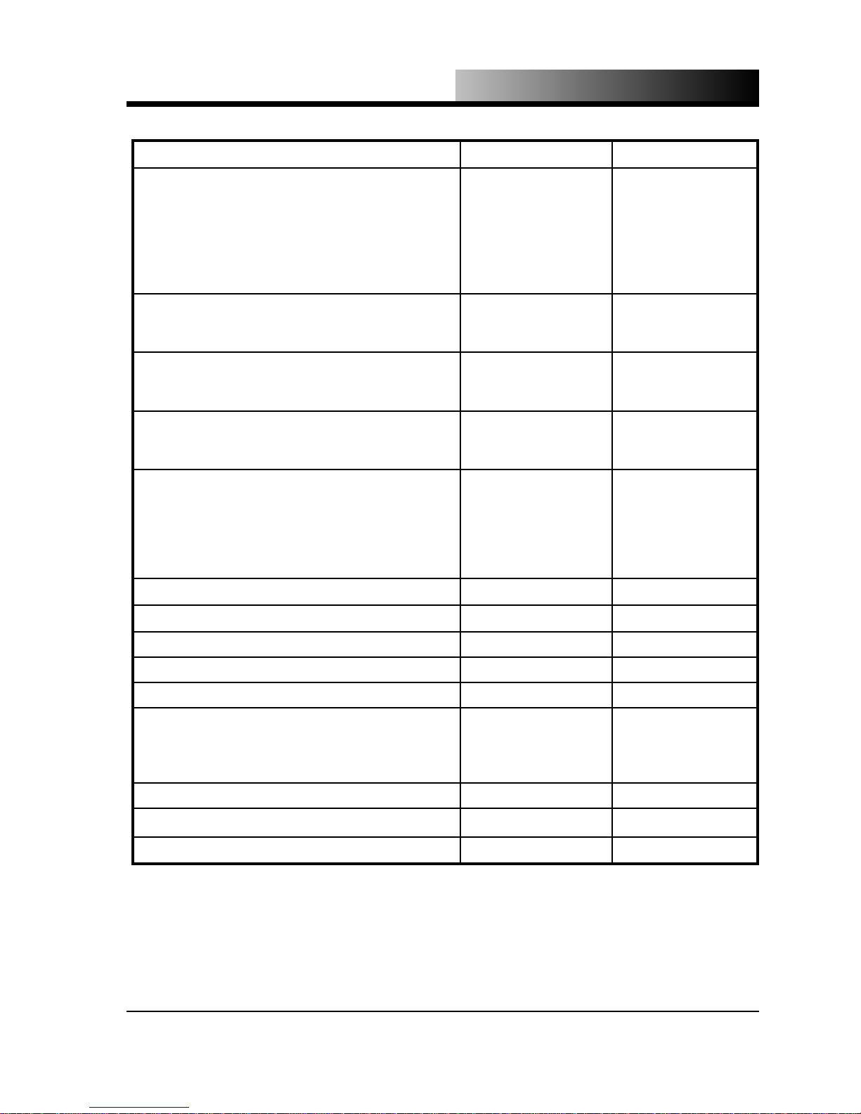
Table 1.1 - Physical Constants of Carbon Dioxide
1.4
Page 12

INTRODUCTION
LEARNING MORE ABOUT CARBON DIOXIDE
An important part of maintaining a carbon dioxide dry ice pelletizer is understanding
the properties of CO
. Therefore, maintenance and service of your pelletizer should
2
be performed only by a qualified carbon dioxide equipment technician.
To start or increase your knowledge of carbon dioxide, we recommend that you begin with the pamphlets and literature from the CGA (Compressed Gas Association).
The CGA has a number of pamphlets and videos on CO
and CO2 equipment.
2
We recommend:
G-6 Carbon Dioxide
G-6.1 Standard for Low Pressure Carbon Dioxide Systems at Consumer S ites
G-6.4 Safe Transfer of Low Pressure Liquefied Carbon Dioxide in Cargo Tanks,
Tank Cars and Portable Containers
AV-7 Characteristics and Safe Handling of Carbon Dioxide
The CGA has other publications, vi deos, etc. that pertain to the CO
and CO2 equip-
2
ment. Contact the CGA for a list of available publications at:
Compressed Gas Association
1725 Jefferson Davis Hwy.
Suite 1004
Arlington, VA 22202-4102 USA
Phone: (703) 412-0900
1.5
Page 13

CARBON DIOXIDE DRY ICE PELLETIZER
INTRODUCTION
SPECIFICATIONS
METHOD OF OPERATION: The dry ice Pelletizer consists of a system for
injecting liquid CO
into a compression cylinder. The process of reducing the
2
pressure on the liquid from approximately 300 psi (20.68 bar), below the Triple
Point, to atmospheric pressure causes about 40% of the carbon dioxide to
change to a solid. The remaining carbon dioxide changes to a vapor and is
vented from the machine. Finally, the solid is hydraulically extruded through
a die to form dry-ice pellets. These pellets can range in size from 0.114” (2.9
mm) to 3/4” (19.05 mm) diameter. The LB-450 disk press has an extra step
that takes the extruded pellets and forms them into a disk 4” (101.6 mm) in
diameter by 1/2” (12.7 m m) thick.
HYDRAULIC SYSTEM:
• High oil temperature automatic shut-off (greater than 150 ºF (65.5 ºC))
• Low oil level automatic shut-off
• High pressure relief valve (see Tabl e 1.2 on page 1.7 for actual setting of
each model
ELECTRICAL: Available to meet electrical requirements worldwide
(Capacities may vary due to frequency variation.)
FEATURES:
• U.S.D.A (United States Department of Agriculture) approved
• Automatic (unattended) operat ion
1.6
Page 14

INTRODUCTION
High
Capacity
LB-450
1500
HP-1000 DE89RB-
1000
57 3/4”
(146.7cm)
46"
(116.8 cm)
50"
(127.0 cm)
46"
(116.8 cm)
46"
(116.8 cm)
128 7/8”
(327.3cm)
78"
(198.0 cm)
118"
(300 cm)
117"
(297.2 cm)
117"
(297.2 cm)
93”
79"
81"
84"
81"
8000 lbs
(236.2cm)
2500 lbs
(201 cm)
5018 lbs
(206.0 cm)
4000 lbs
(213.4 cm)
3700 lbs
(206.0 cm)
(3636 kg)
40 seconds
per cylinder
(1136 kg)
(2280 kg)
(1818 kg)
(1682 kg)
per disc
8 seconds
per cylin-
40 seconds
55 seconds
per cylinder
55 seconds
per cylinder
2
der
50 hp
(37.3 kW)
15 HP
(11.2 kW)
25 HP
(18.6 Kw)
25 HP
(18.6 kW)
20 HP
(15 kW)
ters)
(832.7 li-
220 gallons
(455 liters)
120 gallons
(455 liters)
120 gallons
(455 liters)
120 gallons
(455 liters)
120 gallons
4000psi
(276 bar)
(152 bar)
2200 psig
3000 psig
(206.8 bar)
3000 psig
(206.8 bar)
3000 psig
(206.8 bar)
HP-500 DE89RB-
46"
46"
500
117"
(116.8 cm)
117"
(116.8 cm)
HP-200 DE89RB-
MODEL DE89RB-
40"
40"
100-US
WIDTH
40"
(101.6 cm)
40"
(101.6 cm)
LENGTH
84"
(297.2 cm)
81"
(297.2 cm)
60"
(101.6 cm)
60"
(101.6 cm)
HEIGHT
3200 lbs
(213.4 cm)
2770 lbs
(206.0 cm)
945 lbs
(152.4 cm)
945 lbs
(152.4 cm)
APPROX.
(1455 kg)
55 seconds
(1256 kg)
55 seconds
(429 kg)
43 seconds
(429 kg)
25 seconds
WEIGHT
CYCLE TIME
per cylinder
per cylinder
per cylinder
1 2 1 1 2 2 2 3
per cylinder
CYLINDERS
NUMBER OF
25 HP
(18.6 kW)
15 HP
(11.2 kW)
7.5 HP
(5.6 kW)
7.5 HP
(5.6 kW)
MOTOR
(455 liters)
120 gallons
(455 liters)
120 gallons
35 gallons
(133 liters)
35 gallons
(133 liters)
HYDRAULIC
OIL CAPACITY
3000 psig
(206.8 bar)
3000 psig
(206.8 bar)
Table 1.2 - Dry Ice Pelletizer Dimensional Data
(186 bar)
2700 psig
(186 bar)
2700 psig
RELIEF
PRESSURE
HYDRAULIC
1.7
Page 15

SECTION
2
CARBON DIOXIDE
SAFETY
2.0
Page 16
CARBON DIOXIDE SAFETY
The text in this section has been adapted from CGA (Compressed Gas Association)
publication CGA G-6 – 1984: Carbon Dioxide
.
GENERAL SAFETY CONSIDERATIONS
Gaseous carbon dioxide is an asphyxiant. Concentrations of 10% or more ca n produce unconsciousness or death. Lower concentrations may cause headache, sweating, rapid breathing, increased heart rate, shortness of breath, dizziness, mental depression, visual disturbances, and shaking. The seriousness of the latter manifestations is dependent on the concentration of carbon dioxide and the length of time the
individual is exposed.
Carbon dioxide is an odorless gas and should be treated as a material with poor
warning properties. It is denser than air, and high concentrations can persist in open
pits, tanks, or low depressions on the terrain. Before entering such an area, carbon
dioxide monitoring should be carried o ut and the area cleared by forced venti l ati on,
or a self-contained, supplied air respirator should be worn.
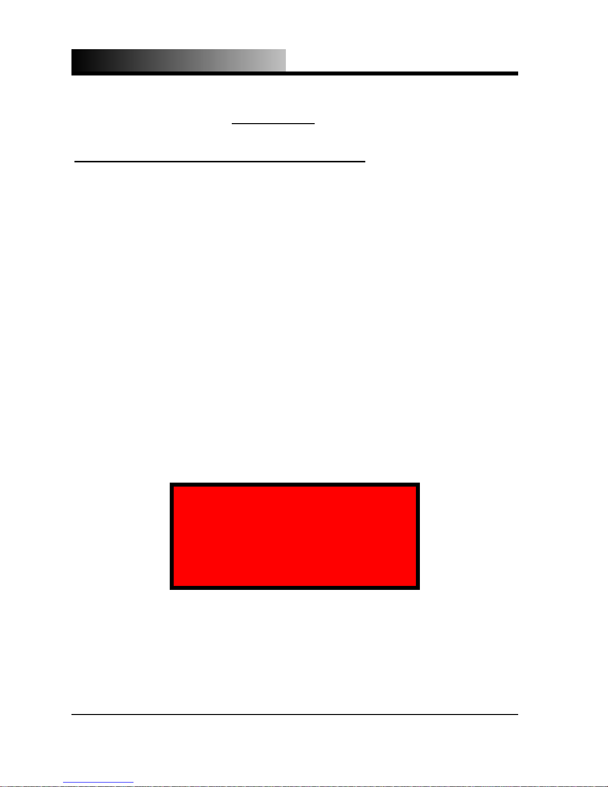
Appropriate warning signs shoul d be affixed outside of those areas where high concentrations of carbon dioxide gas can accumulate. An example is shown below:
CAUTION - CARBON DIOXIDE GAS
Ventilate the area before entering.
A high CO
gas concentration
2
may occur in this area
and may cause suffocation.
2.1
Page 17

CARBON DIOXIDE SAFETY
RESCUE
Do not attempt to remove the individual without utilizing proper rescue equipment or
you may also become a casualty. If the exposed person is unconscious, obtain assistance and put into effect the established emergency procedures.
INHALATION FIRST AID
Inhalation of gaseous carbon dioxide can adversely affect body function. Skin, eye,
or mouth contact with dry ice (solid carbon dioxide) or compressed carbon dioxide
can cause adverse effects.
If a person has inhaled large amounts of carbon dioxide and is exhibiting adverse effects, move the exposed individual to fresh air at once. If breathing has stopped, perform artificial respiration. Keep the affected person warm and at rest. Get professional medical attention immediately.
EXTERNAL EXPOSURE FIRST AID
Skin or mouth contact with dry ice or with vapor or liquid carbon dioxide discharged
from a container may result in frostbite, causing skin lesions or more serious injury
from deep freezing of the tissues.
If dry ice or compre ssed CO
the exposure immediately. If frostbite has occurred, obtain professional medical attention immediately. Do not rub the area. Do not apply heat warmer than 107 °F
(41.7 °C).
Eye contact with dry ice or compressed CO
Frostbite of the eye structure may also occur.
If dry ice or CO
vapor or liquid comes in contact with the eyes, stop the exposure
2
and obtain professional medical attention immediately.
vapor comes in contact with the skin or mouth, stop
2
should be considered as a corneal burn.
2
2.2
Page 18

Page 19

SECTION
3
INSTALLATION
3.0
Page 20

INSTALLATION
INSTALLATION
Following is the standard installation procedure for a Tomco2 Equipment Co. carbon
dioxide dry ice pelletizer. Note: This should be performed by a qualified carbon
dioxide equipment technician only. Refer to Figure 3.1 on page 3.3.
Note: A liquid CO
quired for satisfactory performa nce. Contact Tomco
pressure will be lower than 250 psig (17.23 bar). Contact Tomco
liquid CO
Dew point will be above –60°F (-51.1°C).
2
supply pressure of 250 to 300 psig (17.23 to 20.68 bar) is re-
2
Equipment Co. if liquid CO2
2
Equipment Co. if
2
1. Install an insulate d connecting line between the liquid process isolation valve on
the carbon dioxide storage unit and the 1” FNPT (1/2” on 100lb and 200lb machines) (1 1/2” on high capacity machines) connection on the rear of the pelletizer. We recommend that you use pre-insulated (2 1/2” (63.5 mm) urethane) 1
1/8” (1 5/8” on high capacity) Type K copper. However, 1” NPT (1 1/2” on high
capacity) schedule 80 seamless pipe can be substituted. Include in this line a core
type liquid CO
filter. We recommend a Sporlan Valve Co. model C-1449G for
2
1 1/8” copper or a Sporlan Valve Co. model C-1448P for 1” NPT pipe. Each of
these filters uses a single Sporlan Valve Co. core model RC-4864. (Filters are
available from Tomco
25’ (7.62 m). Tomco
Parts and Service.) This line should be no longer tha n
2
recommends the use of an automatic va por purge devic e
2
on any pelletizer that has more than 25’ (7.62m) of liquid supply piping. Contact Tomco
Equipment Co. if the installation will require more than
2
25’ (7.62m) of liquid supply pipi ng. The above is for a single machine opera tion.
If several machines are connected to the same liquid line, consider using sizes
larger than mentioned above.
Using an undersized liquid line will result in decreased production.
2. Install a connecting line between the vapor process isolation valve on the carbon
dioxide storage unit and the 1/4” FNPT connection on the rear of the pelletizer.
The construction material of this line is not critical and is up to the installer’s discretion, but it must be approved for at least 350 psig (24.1 bar).
3.1
Page 21
INSTALLATION
Note: If isolation valves are included in the connecting lines (steps 1 & 2),
you must install a safety relief valve between the optional isolation valve and
the liquid or vapor process isol ation valves at the storage unit in the event
that carbon dioxide becomes trapped between the two valves.
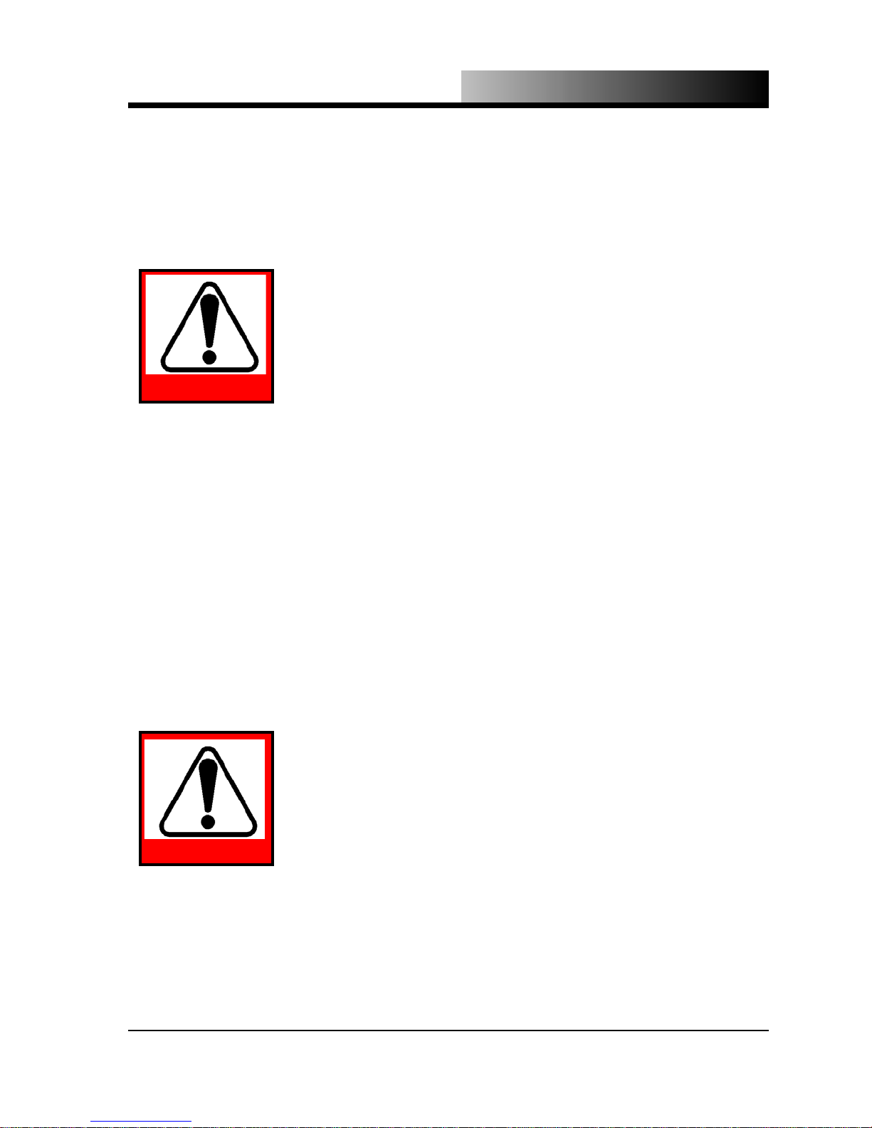
TRAPPING CARBON DIOXIDE IN A PIPE WITHOUT A SAFETY RELIEF VALVE CAN RESULT IN
A RUPTURE OF THE PIPE CAUSING SERIOUS
INJURY OR DEATH!
DANGER
3. Install a low-pressure check valve (no greater than 5 psi cracking pressure) on the
exhaust port of each heat exchanger and vent to the outdoors using either a flexible hose or suitable piping. Tomco
valves and piping if needed. Slope piping at least 1/4” per foot (20mm per me ter)
away from the pelletizer and include a downturn in the piping to prevent moisture
from entering the pelletizer.
Note: Forced air ventilation is not a sufficient means of removing carbon
dioxide vapor. The exhaust ports must be vented to the outdoors.
Parts and Service can supply the check
2
CARBON DIOXIDE IS AN ASPHYXIANT AND
WHEN RELEASED IN HIGH CONCENTRATIONS
AND IN CONFINED AREAS CAN CAUSE SUFFOCATION AND DEATH! CO2 VAPOR IS HEAVIER
THAN AIR AND WILL ACCUMULATE IN LOW AR-
DANGER
4. Fill the hydraulic fluid reservoir to the top of the sight glass with a good quality
hydraulic fluid (R ando HD68 or equal) with a fluid viscosity of 150-300 SUS
EAS OR DEPRESSIONS.
(ISO 32-68) @ 100 ºF (37.7 ºC).
3.2
Page 22

INSTALLATION
Note: U.S.D.A. appr oved equipment must use a food grade hydraulic fluid
with similar properties (Citgo Clarion FG ISO 68 or equal).
5. Install conduit s uitable for four wires between the top right side of the control
panel (above the transformer) and the rear outer panel. Use wires that are the
same size or larger than the largest gauge wires in the control panel. Use clamp
type conduit bulkhead fittings with anti-chafe bushings.
6. Install three wires and a protective earth wire (see included electrical drawing for
wire size) from an appropriate power source through the conduit, leaving enough
wire inside the control panel to reach the top of the disconnect switch. Attach
the green protective earth ground wire to the ground terminal. Ground the pelletizer before use because static electricity can build up on the pelletizer under certain conditions.
Be sure that the power source is
WARNING:
turned off.
7. Strip the proper amount (as recommended by the ferrule manufacturer) of insulation from the wires and secure ferrules on the bare ends. Place ends in the terminals at the top of the disconnect switch (DIS-1) and tighten securely. Close the
control panel and be sure the disconnect switch (DIS-1) is off.
8. Turn on the power at the power source. Turn on the disconnect switch (DIS-1) at
the control panel and press the START button. Observe the rotation of the electric motor. If the motor rotates in the same direction as the reference arrow on
the motor, the electrical connections are correct.
9. If the motor rotates in the wrong direction, press the STOP button. Turn off the
disconnect switch (DIS-1) at the control panel and disconnect the power source.
Open the control panel and swap any two leads at the top of the disconnect
switch (DIS-1). Be sure to tight en the terminal connections securely.
3.3
Page 23
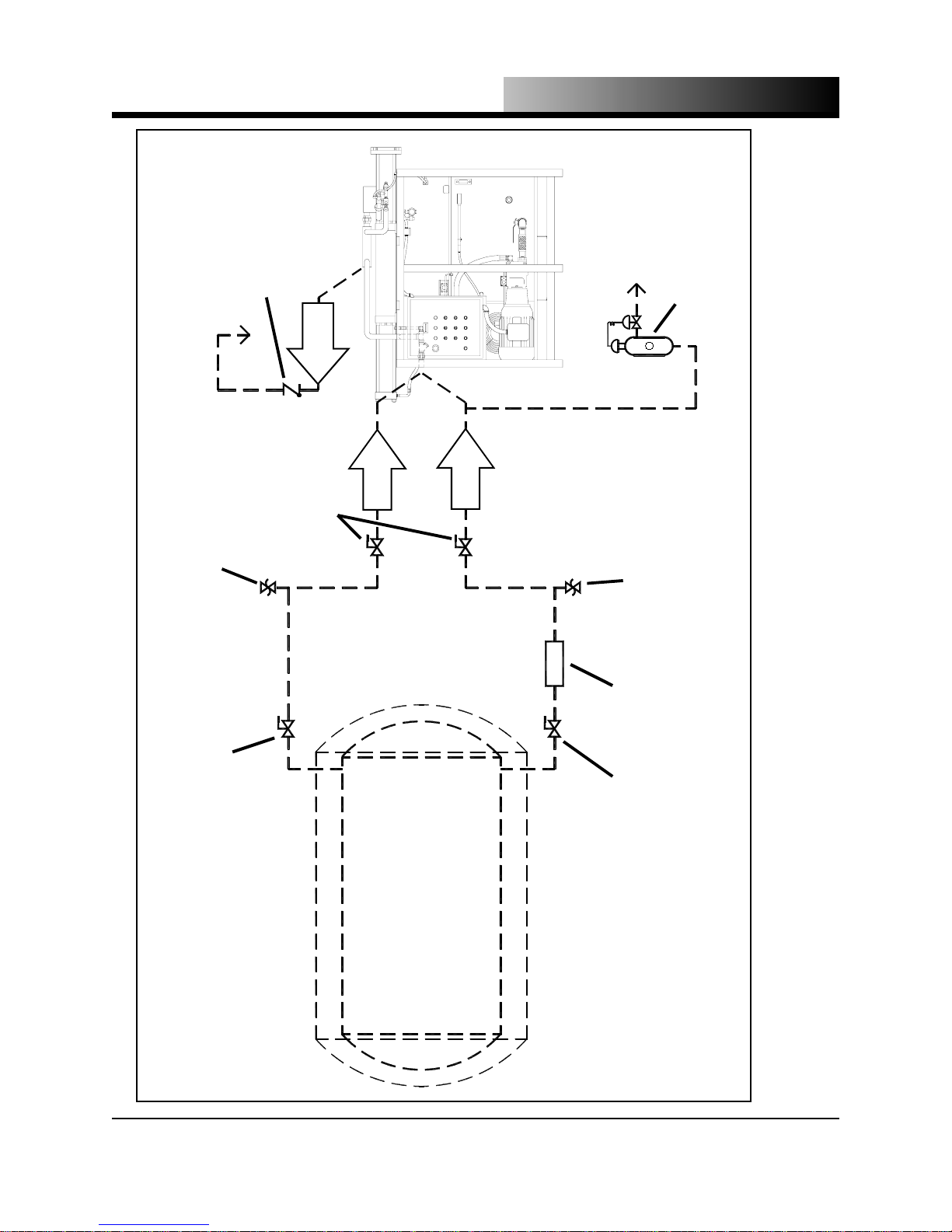
INSTALLATION
VENT TO ATMOSPHERE
LOW-PRESSURE
CHECK VALVE
OPTIONAL
VENT TO
OUTDOORS
AND TURN DOWN
2
EXHAUST
CONNECT FROM
HEAT EXCHANGER
2
CONNECT TO
CONNECT TO
1/4” FNPT
1” FNPT
100LB and 200LB
use 1/2” FNPT High Capacity
use 1 1/2” FNPT
2
2
(P.N. 17001-CA)
OPTIONAL AUTOMATIC
VAPOR PURGE DEVICE
AVAILABLE FROM TOMCO
SAFETY RELIEF VALVE
SET AT 450 psig (31 bar)
NOT BY TOMCO
OPTIONAL ISOLATION
VALVES AT PELLETIZER
CONNECTIONS
NOT BY TOMCO
(REQUIRED IF OPTIONAL
(REQUIRED IF OPTIONAL
ISOLATION VALVE USED)
SAFETY RELIEF VALVE
2
FILTER
LIQUID CO
ISOLATION VALVE USED)
SET AT 450 psig (31 bar)
NOT BY TOMCO
(OPTIONAL)
VALVE & PIPING
Figure 3.1 - Typical Pelletizer recommended installation
VAPOR SUPPLY ISOLATION
MAXIMUM OAL 25’ (7.62 m)
LIQUID SUPPLY ISOLATION
CARBON DIOXIDE
STORAGE UNIT
VALVE & INSULATED PIPING,
3.4
Page 24

Page 25

SECTION
4
OPERATION
&
MAINTENANCE
4.0
Page 26

OPERATION & MAINTENANCE
MANUAL OPERATION – SWITCH / PUSHBUTTON
CONTROLS
Note: Manual operation is not satisfactory for production purposes and should only
be used to check the pelleti z er for proper operation. For pelletizers that have two
cylinders, do not operate both cylinders manually at the same time.
1. Turn on electrical power to the control panel.
2. Be sure the EMERGENCY STOP button is pulled out.
3. Turn the MAN/AUTO switch to the MAN (manual) position.
4. If the pelletizer has two cylinders, place the A/B/A&B switch to the desired cylinder, either A or B. Do not operate both cylinders manually at the same time.
5. Place the corresponding injection switch (A INJ or B INJ) to OFF.
6. Be certain that the compression cylinder is completely retracted and inject liquid
into the compression cylinder by holding the injection switch (A INJ or B
CO
2
INJ) in MAN (manual) position for 20 - 30 seconds, and then release the switch.
Note: The injection switch will not lock in the MAN (manual) position and
must be held for the duration of the liquid CO
injection
2
DO NOT INJECT LIQUID CARBON DIOXIDE INTO
THE CYLINDER UNLESS THE CYLINDER IS COMPLETELY RETRACTED. DOING SO WILL RESULT
IN CARBON DIOXIDE BEING INJECTED BEHIND
THE PISTON AND WILL RESULT IN DAMAGE TO
WARNING
7. Extrude dry ice through the extrusion die by holding the corresponding cylinder
switch (A CYL or B CYL) in EXT (extend) position until the cylinder fully extends, and then release the switch.
THE COMPRESSION CYLINDER, PISTON AND ROD.
4.1
Page 27
OPERATION & MAINTENANCE
8. Hold the corresponding cylinder switch (A CYL or B CYL) in RET (retract) po-
sition until the cylinder fully retracts, and then release the switch.
9. To continue manual operation, repeat Steps 6 - 8.
AUTOMATIC OPERATION – SWITCH / PUSHBUTTON
CONTROLS
1. Turn on electrical power to the control panel.
2. Be sure the EMERGENCY STOP button is pulled out.
3. Depending on the length of liqui d supply lines from the carbon dioxide st orage
unit, it may be a long time before the machine starts making ice. Use the following procedure to get liquid to the machine and reduce the required start-up time.
NOTE: This procedure is not necessary on high capacity pelletizers. To start this
type of machine, simply press the start button. On all other types of pellet izers
manufactured by Tomco
starting automatic operation.
To pre-charge the pelletizer, turn the MAN/AUTO switch to the MAN
(manual) position. Place the corresponding injection switch (A INJ or B INJ)
to OFF. Be certain that the compression cylinder is completely retracted and in-
, it may be necessary to pre-charge the pelletizer before
2
ject liquid CO
(A INJ or B INJ) in MAN (manual) position until vapor begins to flow through
the extrusion die, and then release the switch. If the pelletizer has two cylinders and both will be used for automatic operation, repeat this process for the
other cylinder.
into the compression cylinder by holding the injection switch
2
DO NOT INJECT LIQUID CARBON DIOXIDE INTO
THE CYLINDER UNLESS THE CYLINDER IS COMPLETELY RETRACTED. DOING SO WILL RESULT
IN CARBON DIOXIDE BEING INJECTED BEHIND
THE PISTON AND WILL RESULT IN DAMAGE TO
WARNING
THE COMPRESSION CYLINDER, PISTON AND ROD.
4.2
Page 28
OPERATION & MAINTENANCE
4. Turn the MAN/AUTO switch to the AUTO (automatic) position.
5. If the pelletizer has two cylinders, place the A/B/A&B switch to the desired selection, either A or B for single cylinder operation, or A&B for dual cylinder operation.
6. Push the START button to begin operation.
7. Periodically monitor the compression cylinder pressure by observing the gauge(s)
at the front of the extruder. The compression cylinder pressure should be approximately 35 - 40 psig (2.4 - 2.8 bar) during the injection cycle. If the pressure
is outside of this range, see Section 5 - TROUBLE- SHOOTING.
Note: High Capacity machines have a five-cycle start procedure to facilitate starting
the machine. After a plug has formed, both injection valves will open at the be ginning of the injection cycle. The valves should be adjusted so the pressure is
30-35 psi (2-2.4 bar) at the beginning of the injection cycle. The pressure should
slowly climb to 40 psi (2.8 bar), which will cause the lower valve to close. The
pressure in the chamber should drop to around 20 psi (1.3 bar) and should peak
at about 40 psi (2.8 bar) at the end of the cycle.
WARNING: IF THE METERING VALVE IS SET TOO
HIGH, THE INJECTION VALVE WILL CYCLE ON AND
OFF. PROLONGED CYCLING WILL SIGNIFICANTLY
REDUCE THE LIFE OF THE VALVE.
WARNING
8. Periodically monitor the hydraulic pressure by observing the gauge at the hydraulic valve manifold. The hydraulic pressure should spike at the relief setting as
dry ice begins to exit the extrusion die. See Table 1.2 on page 1.7 for the hydraulic pressure relief setting of each model. If the hydraulic pressure sustains the relief setting pressure for more than 5 seconds, see Section 5 - TROUBLESHOOTING.
4.3
Page 29

OPERATION & MAINTENANCE
Note: Vapor venting from the bottom port at the rear of the compression cylinder is
normal. Do not plug or restrict this port by any means.
High capacity machines do not have this port.
9. To end dry ice production, push the STOP button. The pelletizer will complete
the current cycle before stopping.
Note: To stop the pelletizer immediately press the EMERGENCY STOP button.
The pelletizer will not complete the current cycle and CO
compression cylinder. Any CO
left in the compression cylinder will sublime
2
may be left in the
2
and vent to atmosphere through the extrusion die. When the pelletizer is re started, the machine will go through an automatic clean-out cycle before begin ning an injection cycle, so no user action is required when restarting.
4.4
Page 30

OPERATION & MAINTENANCE
MAINTENANCE
AFTER THE FIRST 48 HOURS OF OPERATION
Check the torque value on the die bolts, tie rod bolts, and web plate bolts
according to Figures 4.3 on pages 4.13 - 4.16. If necessary re-torque following
the procedures found on page 4.12.
WEEKLY
• Inspect all metal surfaces for rust or damage to paint. Repair as needed.
• Inspect hydraulic lines for signs of a leak. Have leaks repaired by a qualified
equipment service technician.
CO
2
• Check the hydraulic fluid level at the sight glass and add hydraulic fluid as
needed.
• Check to be sure that all covers and guards are in place and functioning properly. Make any repairs or replacements as needed.
• Check oil cooler for clogging and clean if necessary.
AFTER EVERY 500 HOURS OF OPERATION
Check the torque value on the die bolts, tie rod bolts, and web plate bolts
according to Figures 4.3 on pages 4.13 - 4.16. If necessary re-torque following
the procedures found on page 4.12.
AFTER EVERY 2000 HOURS OF OPERATION
Compression Cylinder Rebuild
Refer to Figures 4.2 on pages 4.8 - 4.11 for the exploded view of the
hydraulic cylinder and compression cylinder major components.
1. Disconnect electrical power and follow yo ur company’s lock out and tag out safety
procedures.
4.5
Page 31

OPERATION & MAINTENANCE
2. Close the liquid process and vapor process isolation valves at the carbon dioxide
storage unit and bleed pressure from each line.
3. Remove the extrusion di e cover.
4. Remove the extrusion di e.
5. Remove the rod coupling.
6. Manually extend the compression cylinder piston rod until the piston exits the
end of the compression cylinder.
7. Remove the compression cylinder pist on rod bearing and seal retaining ring.
8. Remove the compression cylinder piston rod bearing and bearing seal.
9. Install new rod bearing and bearing seal.
10.Replace the retaining ring.
11.Remove the wear bands from the compression cylinder piston.
12.Check the set screws in the piston to be sure they are tight (if applicable).
Note: Some models have nylon set screws over the steel set screws. If applicable,
remove the nylon set screws and check the steel set screws for tightness. Replace
the nylon set screws.
13.Install new wear bands on the compression cylinder piston.
14.Reassemble in the reverse order. Be sure to grease the rod coupling with a light
coating of grease.
Note: Be certain that the compression cylinder, compression cylinder piston, and ex trusion die are completely free of all moisture before reassembling. Refer to the
Torquing Procedure on page 4.1 2 for the proper sequence and torque values of
the die bolts and tie rod bolts.
4.6
Page 32

OPERATION & MAINTENANCE
AFTER EVERY 10000 HOURS OF OPERATION
Hydraulic Cylinder Rebuild
(tie-rod cylinders only)
Refer to Figures 4.2 on pages 4.8 - 4.11 for the exploded view of the hydraulic
cylinder and compression cylinder major components.
1. Disconnect electrical power and follow your company’s lock out and tag out
safety procedures.
2. Disconnect the hydra ulic hoses and drain the hydraulic fluid from the hydraulic
cylinder.
3. Remove the hydraulic cylinder end cap.
4. Remove the hydraulic cylinder.
5. Remove the rod coupling.
6. Remove the hydraulic cylinder piston and rod assembly.
7. Remove the hydraulic cylinder rod bearing, bearing seal and rod wiper retaining
ring.
8. Remove the hydraulic cylinder rod bearing, bearing seal and rod wiper.
9. Install new hydrauli c cylinder rod bearing, bearing seal and rod wiper.
10.Replace the retaining ring.
11.Remove the hydraulic cylinder piston seals and wear band.
12.Install new hydraulic cylinder piston seals and wear band.
13.Install the hydraulic cylinder rod and rod coupling.
14.Remove the O-rings from the hydraulic cylinder.
4.7
Page 33

OPERATION & MAINTENANCE
15.Install new O-rings on the hydraulic cylinder and install the hydraulic cylinder.
16.Replace the hydraulic cylinder end cap.
Note: Refer to the Torquing Instructions on page 4.12 for the proper
sequence and torque values of the tie rod bolts.
17.Reconnect the hydraulic hoses and check the hydraulic fluid level at the sight
glass. Add hydraulic fluid as needed.
WELDED CYLINDER REBUILD
Contact Tomco2 for details.
Piston Sleeve replacement procedure (this is a two (2) man operation.)
1. Disconnect all electrical power and follow your company's lock out and tag out
safety procedures. The machine will be easier to work on if it is allowed to warm
to room temperature.
2. Remove the head cover from the die.
3. Remove the die.
4. Remove the webb plate cover.
5. Remove the rod coupling.
6. Remove all tools and keep hands clear of the webb plate area while doing this
pro- cedure. Reconnect the machine to a power source and have an assistant
manually extend the cylinder. Hold the front limit switch closed so the cylinder will extend fully.
7. Retract the cylinder enough to insert an 18" long piece of 4x4" lumber.
8. Manually extend the cylinder to its limits.
9. Prepare a catch pad or some way of catching the piston without damaging it or
4.8
Page 34

OPERATION & MAINTENANCE
allowing it to fall to the floor.
10.Retract the hydraulic cylinder and insert a 4x4" about 50" long and extend the
cylinder. Be sure to keep all hands and tools clear of the cylinder while doing this
operation. Do not allow the board to jam or otherwise catch in the cylinder be
cause the hydraulic cylinder will break it.
11.Carefully lower piston assembly to the floor and stand it vertically on t he floor
with the coupling side up.
12.Remove the setscrews in the sleeve retainer.
13.Remove the sleeve retainer.
14.Slide sleeve off.
15.Install the new sleeve with the chamfered end toward the coupling end.
16.Inspect the piston head and cylinder for signs of metal on metal contact. If the
grooves are rusting or are generating flakes, both the piston and the tube wi ll
have to be replaced.
17.If the piston and cylinder are acceptable, then install the piston into the cylinder.
18.When replacing the piston sleeve, t he cold end seal should be replaced at the
same time.
19.Thread an eye bolt into the rear of the piston and attach a chain.
20.Attach the chain to the hydraulic cylinder.
21.Keep all hands and tools clear of the webb plates while performing this operation.
Have an assistant carefully retract the piston far enough to get it past the seal and
allow the coupling to be attached.
22.Install the coupling.
23.Install the webb plate cover.
4.9
Page 35

OPERATION & MAINTENANCE
24.Check for proper limit switch operation at this point by manually extending and
retracting the hydraulic cylinder.
25.Install the die. Follow the torque procedures outlined in section 4.
26.Install the head cover.
Piston seal replacement procedure.
Leaky seals can sometimes cause a hazardous situation and can allow air to be drawn
into a recovery system. The procedure for replacing the cold end cylinder seals is
outlined below:
Note: If this procedure is done with care, the extrusion die does not have to be re
moved.
1. Allow the machine to thaw out completely before beginning this procedure.
2. Extend the hydraulic cylinder fully.
3. Disconnect all electrical power and follow your company's lock out and tag out
safety procedures.
4. Remove the webb plate cover and set it aside.
5. Remove the seal retainer and retainer ring.
6. Reconnect power and retract the cylinder. The piston should pull the seal out of
the cold end head. Do not retract the cylinder more than about 1/3 of the stroke.
7. Disconnect all electrical power and follow your company's lock out and tag out
safety procedures.
8. Remove the rod coupling.
9. Reconnect power to the machine and retract the cylinder.
10.Disconnect all electrical power and follow your company's lock out and tag out
4.10
Page 36

OPERATION & MAINTENANCE
safety procedures.
11.Carefully pull the old seal off the piston.
12.Install the new seal on the piston as far as possible by hand.
13.Reconnect power to the machine and extend the cylinder.
14.Disconnect all electrical power and follow your company's lock out and tag out
safety procedures.
15.Use the seal retainer ring to press the seal into its final position.
AS REQUIRED
Hydraulic Fluid Change and Filter Replacement
Change the hydraulic fluid and hydraulic fluid filter according to the fluid
manufacturer’s recommendations.
Filter Screen Cleaning or Replacement
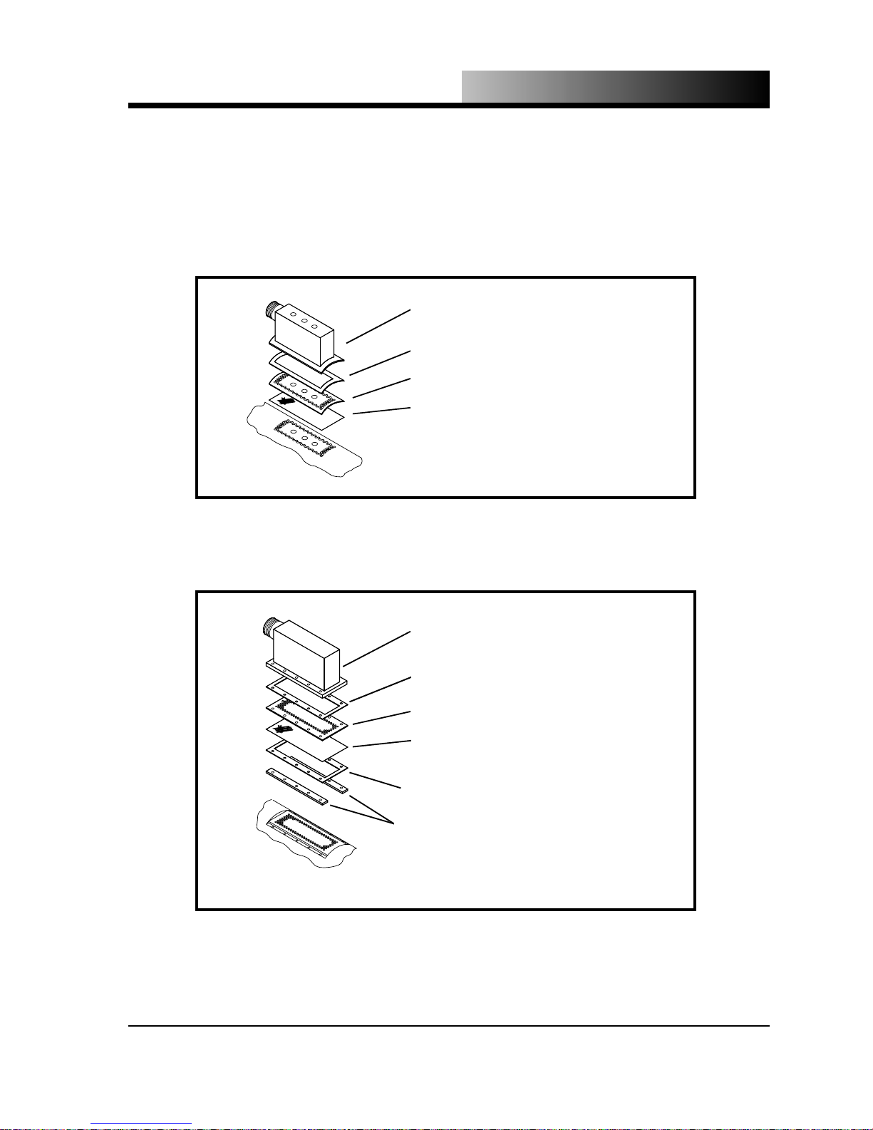
Refer to Figures 4.1 on page 4.7 for the exploded view of the transition box
assembly.
1. Disconnect the exhaust connection at the union fitting on the transition box.
2. Remove the transition box.
3. Remove the filter screen retaining plate.
4. Remove the filter screen, using caution to avoid tearing it.
5. Clean the filter screen with a solvent type cleaner. Note: If filter screen is torn or
damaged, it must be replaced with a new one.
4.11
Page 37
OPERATION & MAINTENANCE
6. Completely dry the filter screen with CO2 vapor or a dry air source.
7. Check all gaskets and replace any that are torn or cracked.
8. Reassemble in the reverse order.
TRANSITION BOX
GASKET
FILTER SCREEN RETAINING PLATE
FILTER SCREEN
Figure 4.1.1 - Models DE89RB-100-US, HP-200 & LB-450
Transition Box Assembly Exploded View
TRANSITION BOX
GASKET (O-RING ON HIGH CAPACITY)
FILTER SCREEN RETAINING PLATE
FILTER SCREEN
GASKET (O-RING ON HIGH CAPAICTY)
SPACERS
Figure 4.1.2 - Models DE89RB-500, DE89RB-1000, HP-500, HP-1000, DE89RB-1500
and High Capacity Transition Box Assembly Exploded View
4.12
Page 38
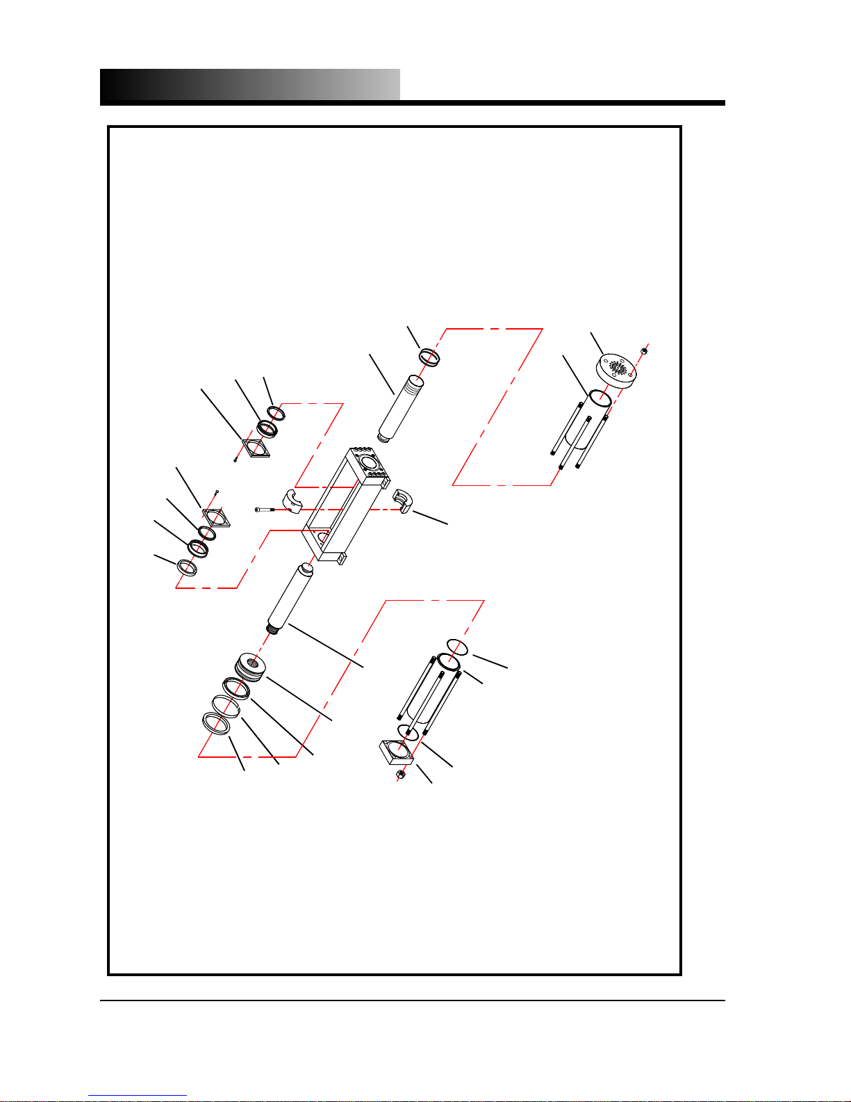
OPERATION & MAINTENANCE
COMPRESSION CYLINDER ROD & PISTON
COMPRESSION CYLINDER PISTON
RETAINING PLATE
RETAINING PLATE
COMPRESSION CYLINDER PISTON
BEARING
COMPRESSION CYLINDER PISTON
WEAR BANDS
EXTRUSION DIE
COMPRESSION CYLINDER
HYDRAULIC CYLI N DER ROD WIPER
HYDRAULIC CYLINDER ROD BEARING
ROD COUPLING
O-RING
HYDRAULIC CYLIN DER ROD BEARING SEAL
HYDRAULIC CYLINDER
O-RING
HYDRAULIC CYLINDER PISTON ROD
HYDRAULIC CYLINDER PISTON
HYDRAULIC CYLINDER PISTON SEAL
HYDRAULIC CYLINDER PISTON WEAR BAND
4.13
HYDRAULIC CYLINDER PISTON SEAL
HYDRAULIC CYLINDER END CAP
Figure 4.2.1 - Models DE89RB-100-US, HP-200 & LB-450 Hydraulic and Compression Cylinde r Exploded View
Page 39
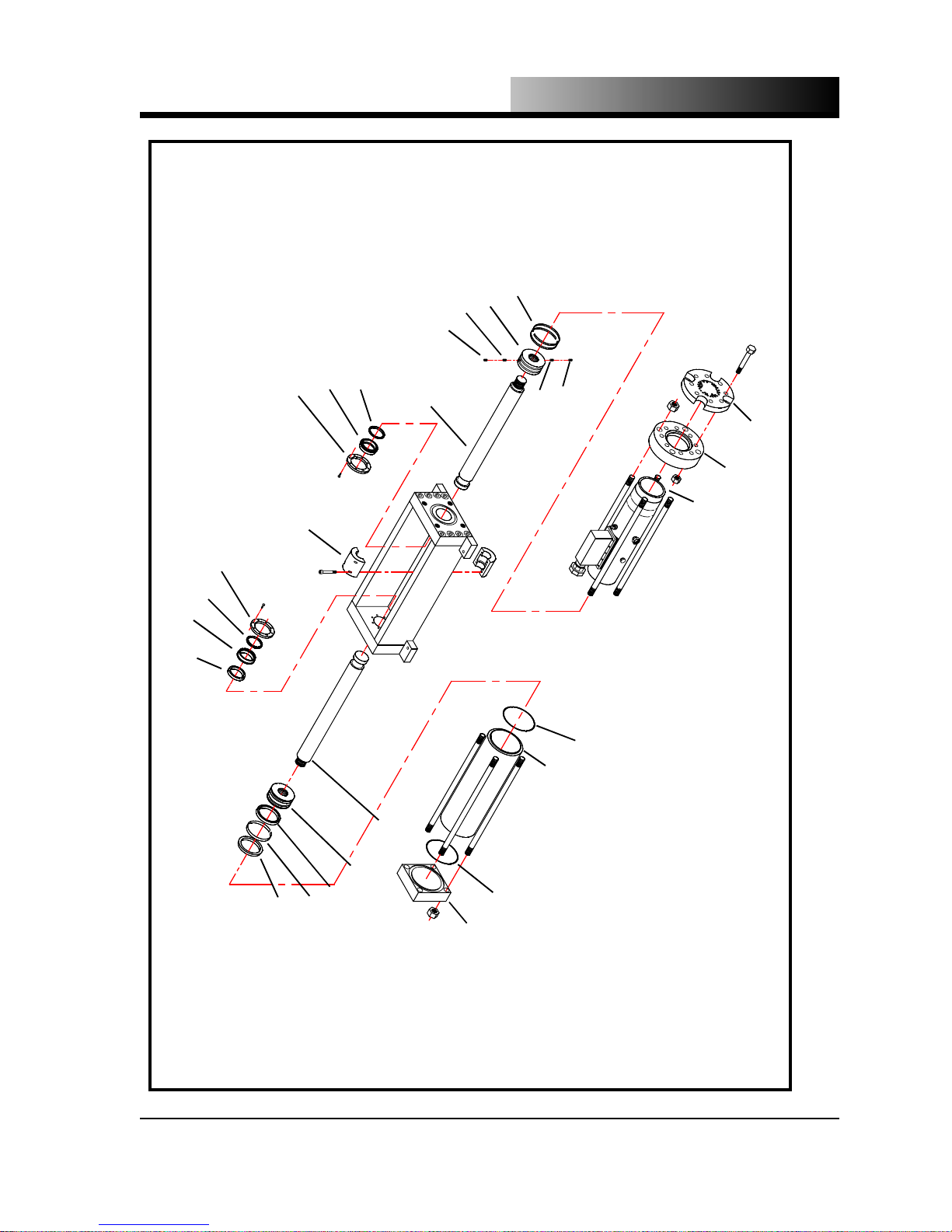
OPERATION & MAINTENANCE
COMPRESSION CYLINDER
PISTON WEAR BANDS
COMPRESSION CYLINDER PISTON
STEEL SET SCREW
NYLON SET SCREW
COMPRESSION CYLINDER PISTON
BEARING
COMPRESSION CYLINDER PISTON
RETAINING PLATE
ROD COUPLING
BEARING SEAL
COMPRESSION CYLINDER PISTON ROD
NYLON SET SCREW
STEEL SET SCREW
EXTRUSION DIE
RETAINING PLATE
HYDRAULIC CYLI N DER ROD WIPER
EXTRUSION DIE RETAINING RING
HYDRAULIC CYLINDER ROD BEARING
O-RING
HYDRAULIC CYLINDER ROD BEARING SEAL
HYDRAULIC CYLINDER
O-RING
WEAR BAND
HYDRAULIC CYLINDER PISTON ROD
HYDRAULIC CYLIN DER PISTON
COMPRESSION CYLINDER
Figure 4.2.2 - Models DE89RB-500 & DE89RB-1000 Hydraulic and Compression Cylinder Exploded View
HYDRAULIC CYLINDER PISTON
HYDRAULIC CYLINDER PISTON SEAL
HYDRAULIC CYLINDER PISTON SEAL
HYDRAULIC CYLINDER END CAP
4.14
Page 40
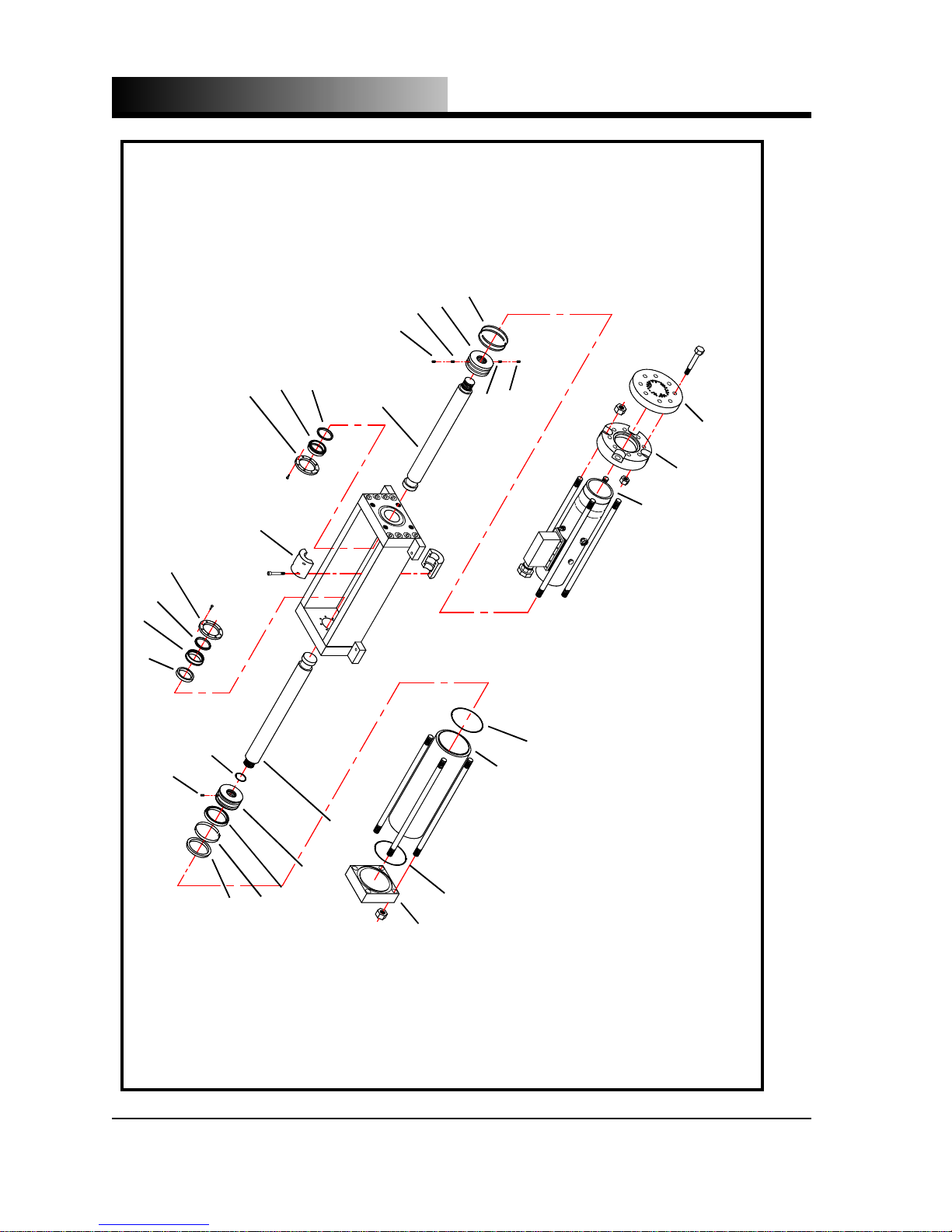
OPERATION & MAINTENANCE
STEEL SET SCREW
NYLON SET SCREW
COMPRESSION CYLINDER PISTON
RETAINING PLATE
COMPRESSION CYLINDER PISTON
ROD COUPLING
BEARING SEAL
BEARING
COMPRESSION CYLINDER PISTON ROD
COMPRESSION CYLINDER PISTON
COMPRESSION CYLINDER
PISTON WEAR BANDS
NYLON SET SCREW
STEEL SET SCREW
EXTRUSION DIE
RETAINING PLATE
HYDRAULIC CYLINDER ROD WIPER
EXTRUSION DIE RETAINING RING
HYDRAULIC CYLINDER ROD BEARING
O-RING
STEEL SET SCREW
HYDRAULIC CYLINDER ROD BEARING SEAL
O-RING
WEAR BAND
HYDRAULIC CYLINDER PISTON ROD
HYDRAULIC CYLINDER PISTON
O-RING
HYDRAULIC CYLINDER
COMPRESSION CYLINDER
Figure 4.2.3 - Models HP-500 & HP-1000 Hydraulic and Compression Cylinder Exploded Vie w
HYDRAULIC CYLINDER PISTON
HYDRAULIC CYLINDER PISTON SEAL
HYDRAULIC CYLINDER PISTON SEAL
4.15
HYDRAULIC CYLINDER END CAP
Page 41
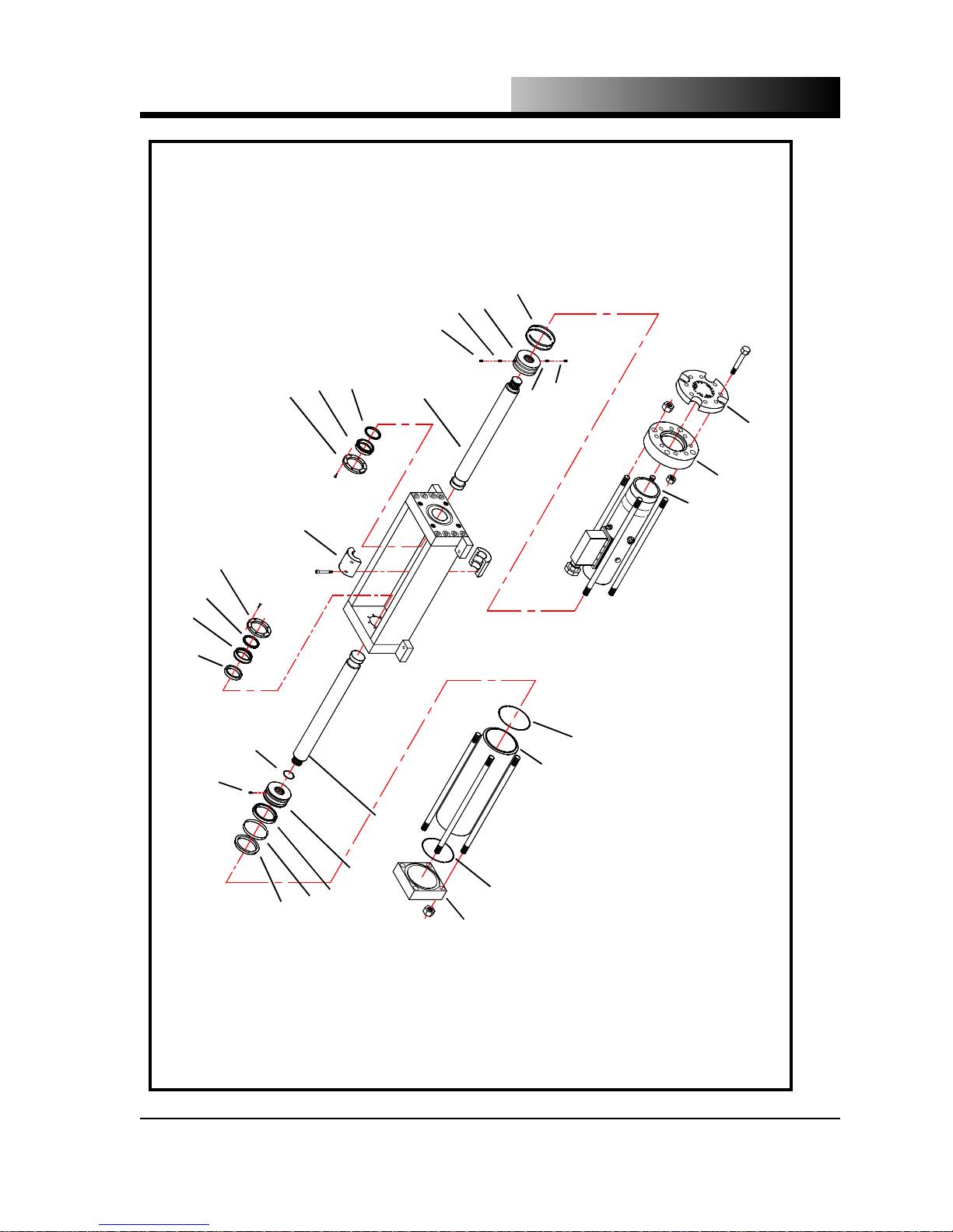
OPERATION & MAINTENANCE
COMPRESSION CYLINDER
PISTON WEAR BANDS
COMPRESSION CYLINDER PISTON
STEEL SET SCREW
NYLON SET SCREW
COMPRESSION CYLINDER PISTON
BEARING SEAL
COMPRESSION CYLINDER PISTON
BEARING
RETAINING PLATE
ROD COUPLING
COMPRESSION CYLIN DE R PI S TON ROD
NYLON SET SCREW
STEEL SET SCREW
EXTRUSION DIE
RETAINING PLATE
HYDRAULIC CYLINDER ROD WIPER
HYDRAULIC CYLINDER ROD BEARING
O-RING
STEEL SET SCREW
HYDRAULIC CYLINDER ROD BEARING SEAL
O-RING
O-RING
HYDRAULIC CYLINDER
COMPRESSION CYLINDER
EXTRUSION DIE RETAINING RING
Figure 4.2.4 - Model DE89RB-1500 Hydraulic and Compression Cylinder Exploded View
WEAR BAND
HYDRAULIC CYLINDER PISTON ROD
HYDRAULIC CYLINDER PISTON
HYDRAULIC CYLINDER PISTON
HYDRAULIC CYLINDER PISTON SEAL
HYDRAULIC CYLINDER PISTON SEAL
HYDRAULIC CYLINDER END CAP
4.16
Page 42

OPERATION & MAINTENANCE
TORQUE PROCEDURES
All Tomco2 Equipment Co. Dry Ice Pelletizers are designed and built to provide
many years of service. However, these pellet izers undergo many cycles of severe
loading and unloading.
In order for the pelletizers to survive the fatiguing encountered with cyclic loading, it
is imperative that key components are torqued evenly and adequately. The torque
value is the amount of work (ft-lb., Nm, m kg) applied to the fastener. This torque
value will apply a large pre-load to the bolt and is very advantageous in reducing the
effects of fatigue. The result is a smaller variation in the cyclic loading occurring
during the extrusion of dry ice.
Figures 4.3 on the following pages show the torque sequences and final torque values for the fasteners that require torquing for each pelletizer model. The fasteners
should be torqued in four (4) steps. Following the torque sequence shown corresponding to the appropriate assembly, torque each fastener to approximately 25% of
the recommended final torque value. Repeat the torque sequence three more times,
each time increasing the value by approximately 25% of the recommended final
torque value.
Example: Model HP-1000 Extrusion Die
Torque Value
Step 1 119 ft-lb (16 m kg) (161 Nm)
Step 2 238 ft-lb (33 m kg) (323 Nm)
Step 3 356 ft-lb (49 m kg) (483 Nm)
Step 4 475 ft-lb (66 m kg) (644 Nm)
Note: All threads must be clean and well lubricated with an appropriate lubricant.
Note: Check the torque value of each fastener immediately following the first 48
hours of operation and subsequently after every 500 hours of operation. Re-torque
if necessary. Repeat this after every scheduled cylinder rebuild.
4.17
Page 43
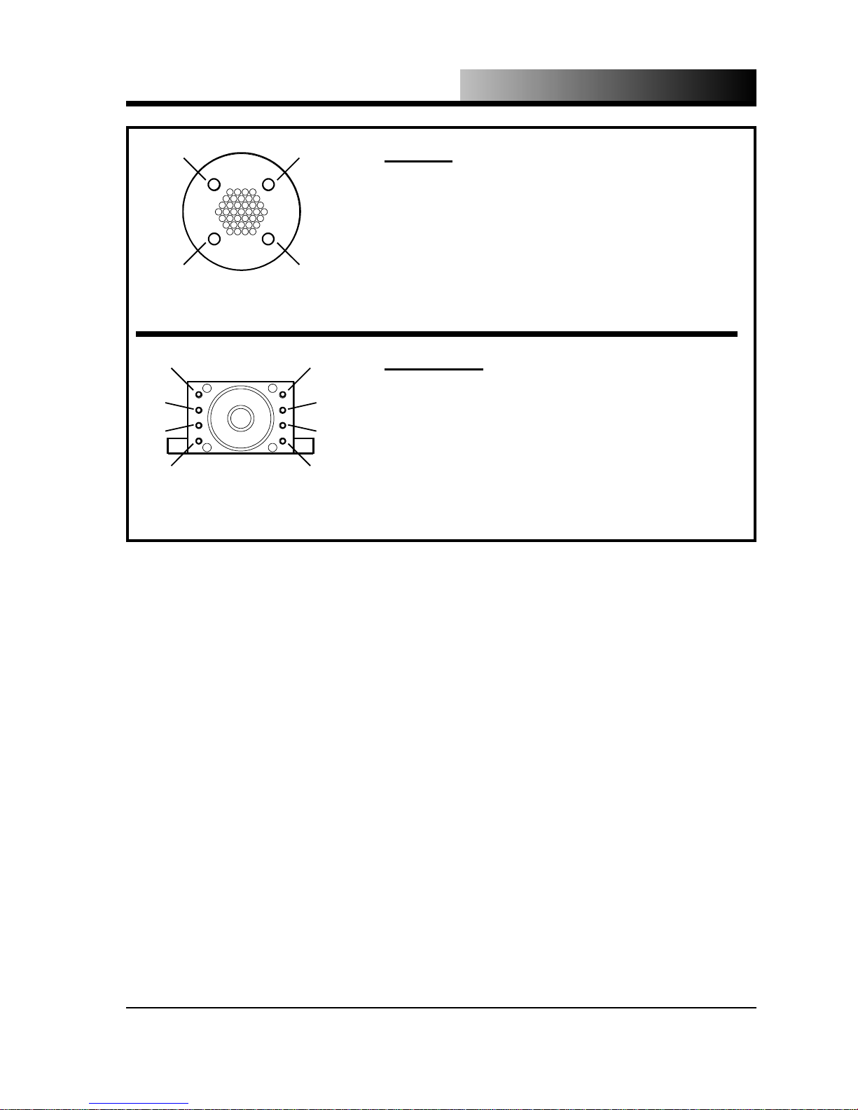
OPERATION & MAINTENANCE
3
2
TIE ROD
TORQUE SEQUENCE
3
7
5 8
2
WEB PLATE
TORQUE SEQUENCE
1
4
1
4
6
TIE ROD
Fastener - 5/8” - 18 UNF tie rod with matching hex nut
Final Torque Value - 190 ft lbs (26 m kg) (258 Nm)
WEB PLATE
Fastener - 1/2” - 13 x 3” SHCS
Final Torque Value - 50 ft lbs (7 m kg) (68 Nm)
Figure 4.3.1 - Models DE89RB-100-US, HP-200 & LB-450
Torque Sequences and Values
4.18
Page 44
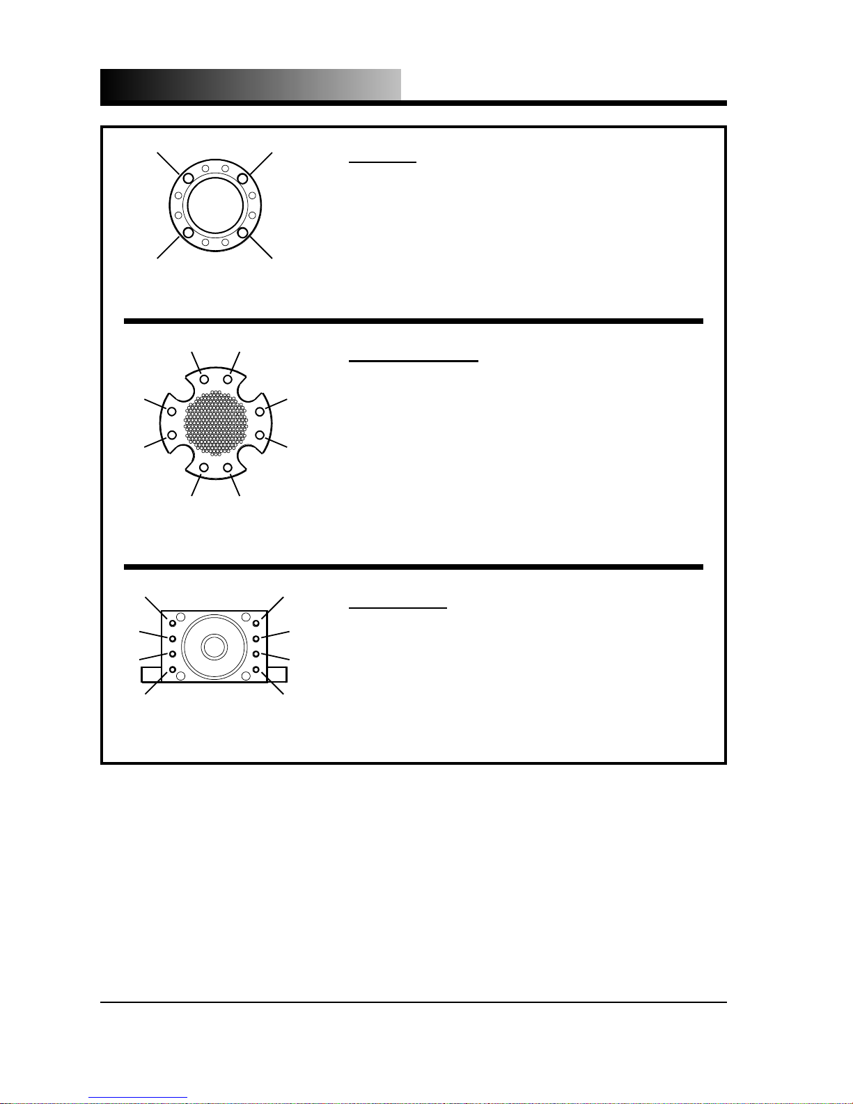
OPERATION & MAINTENANCE
3
2
TIE ROD
TORQUE SEQUENCE
3
5 8
7
2
EXTRUSION DIE
TORQUE SEQUENCE
1
4
1
4
TIE ROD
Fastener - 1” - 14 UNS tie rod with matching hex nut
Final Torque Value - 700 ft lbs (97 m kg) (951 Nm)
EXTRUSION DIE
Fastener - 5/8” - 18 x 3 1/2” UNF Grade 8 SHCS
Final Torque Value - 175 ft lbs (24 m kg) (238 Nm)
6
3
7
5 8
2
WEB PLATE
TORQUE SEQUENCE
1
6
4
Figure 4.3.2 - Models DE89RB-500 & DE89RB-1000
WEB PLATE
Fastener - 7/8” - 14 x 4” UNF SHCS
Final Torque Value - 500 ft lbs (69 m kg) (678 Nm)
Torque Sequences and Values
4.19
Page 45
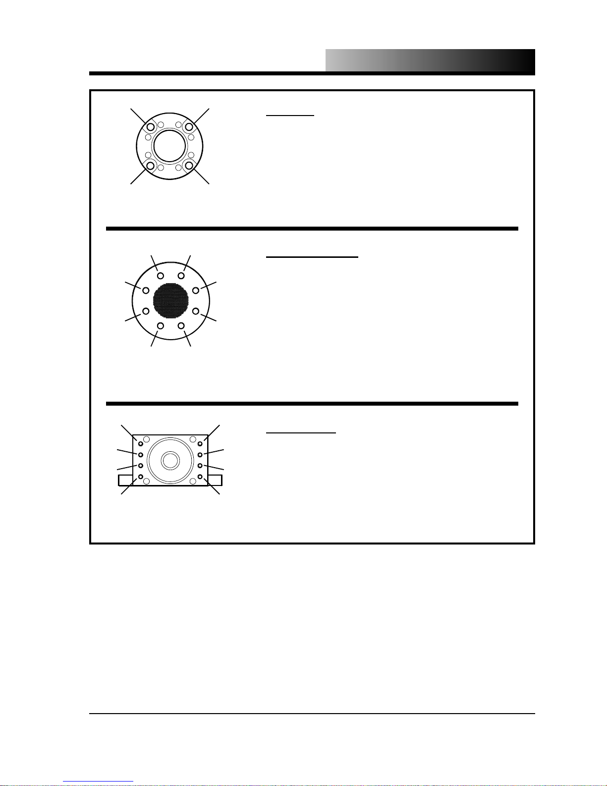
OPERATION & MAINTENANCE
3
2
TIE ROD
TORQUE SEQUENCE
3
5 8
7
2
EXTRUSION DIE
TORQUE SEQUENCE
1
4
1
4
TIE ROD
Fastener - 1 1/4” - 12 UNF Tie Rod with Matching Hex Nut
Final Torque Value - 1250 ft lbs (173 m kg) (1699 Nm)
EXTRUSION DIE
Fastener - 1” - 14 x 6” UNF Grade 8 HHCS
Final Torque Value - 475 ft lbs (66 m kg) (646 Nm)
6
3
7
5 8
2
WEB PLATE
TORQUE SEQUENCE
1
6
4
Figure 4.3.3 - Models HP-500 & HP-1000
WEB PLATE
Fastener - 1 1/4” - 12 x 4” SHCS
Final Torque Value - 1250 ft lbs (173 m kg) (1699 Nm)
Torque Sequences and Values
4.20
Page 46
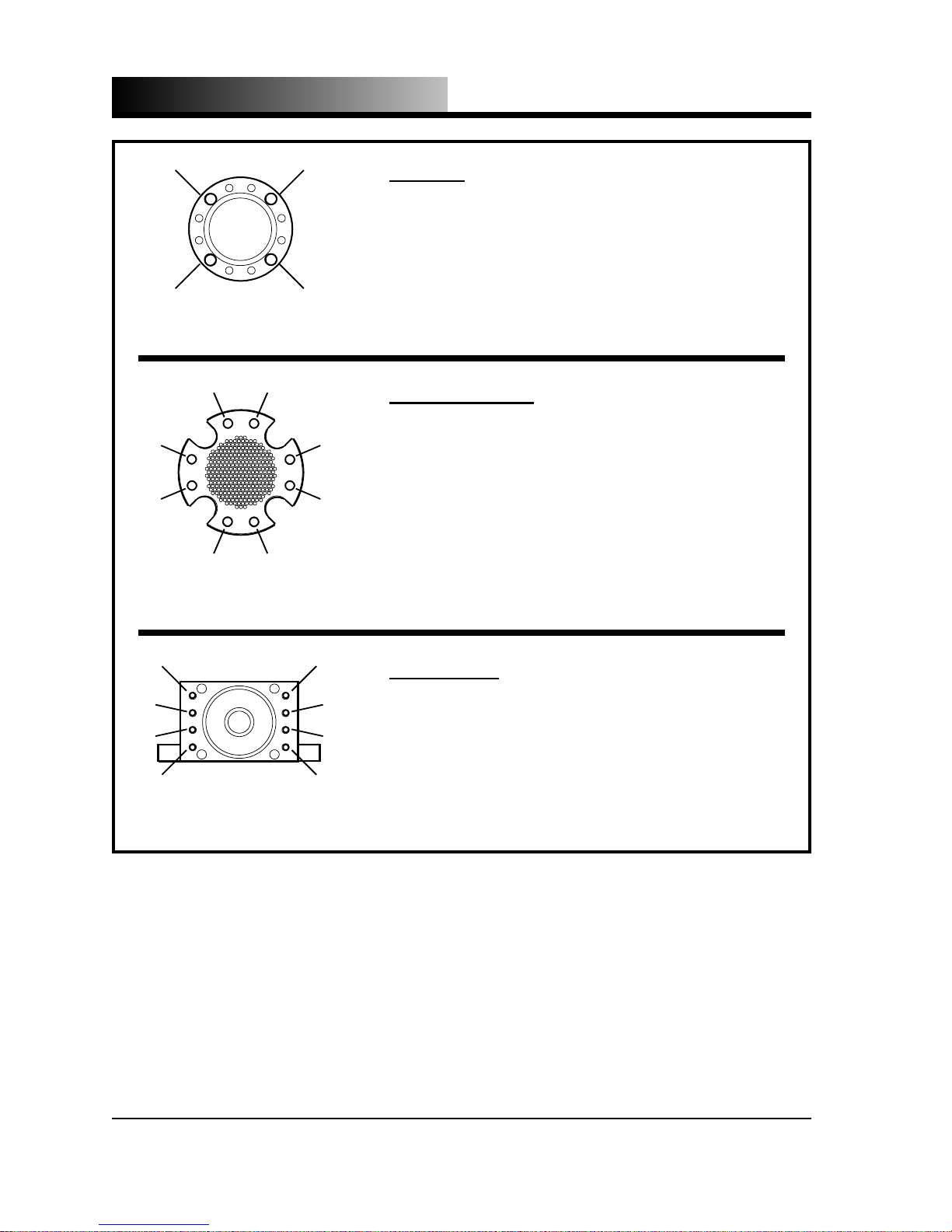
OPERATION & MAINTENANCE
3
2
TIE ROD
TORQUE SEQUENCE
3
5 8
7
2
EXTRUSION DIE
TORQUE SEQUENCE
1
4
1
4
TIE ROD
Fastener - 1 1/8” - 12 UNF Tie Rod with Matching Hex Nut
Final Torque Value - 950 ft lbs (131 m kg) (1291 Nm)
EXTRUSION DIE
Fastener - 3/4” - 16 x 3 1/2” UNF Grade 8 SHCS
Final Torque Value - 280 ft lbs (39 m kg) (381 Nm)
6
3
7
5 8
2
WEB PLATE
TORQUE SEQUENCE
1
6
4
WEB PLATE
Fastener - 1” - 14 x 4 1/2” UNF
Final Torque Value - 700 ft lbs (97 m kg) (951 Nm)
Figure 4.3.4 - Model DE89RB-1500
Torque Sequences and Values
4.21
Page 47
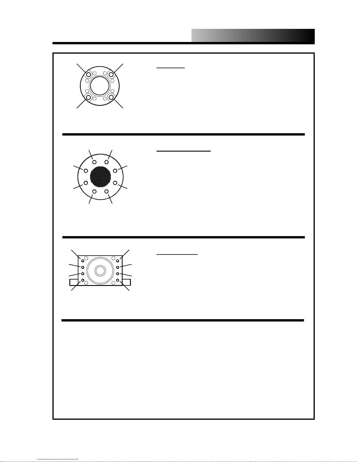
OPERATION & MAINTENANCE
3
2
TIE ROD
TORQUE SEQUENCE
3
5 8
7
2
EXTRUSION DIE
TORQUE SEQUENCE
1
4
1
4
TIE ROD
Fastener - 1 1/2” - 12 UNF Tie Rod with Matching Hex Nut
Final Torque Value - 1800 ft lbs (249 m kg) (2446 Nm)
EXTRUSION DIE
Fastener - 1” - 14 x 7” UNF Grade 8 HHCS
Final Torque Value - 530 ft lbs (73 m kg) (720 Nm)
6
3
7
5 8
2
WEB PLATE
TORQUE SEQUENCE
1
6
4
WEB PLATE
Fastener - 1 1/4” - 12 x 3 3/4” frt. SHCS (4” rear)
Final Torque Value - 600 ft lbs (83 m kg) (815 Nm)
Figure 4.3.5 - High Capacity
Torque Sequences and Values
4.22
Page 48

Page 49

SECTION
TROUBLE-
5
SHOOTING
5.0
Page 50

TROUBLESHOOTING
All troubles hooting should only be performed by a qualified carbon dioxide service
technician. Reference the appropriate Wiring Schematic Drawing and the appropriate Process and Instrumentation Diagram Drawing in the Appendix of this manual
for component identification.
PROBLEM POSSIBLE CAUSE REMEDY
Compression cylinder pressure too high
(55 - 60 psig (3.79 - 4.13 bar))
Compression cylinder pressure too high
(exceeds 60 psig (4.13 bar))
Compression cylinder pressure too low
(0 - 20 psig (0 - 1.37 bar))
1. Moisture or debris on the exhaust fil ter screen
2. Restriction in the vapor exhaust line
3. Metering valve open too much
4. Injection valve not closing properly
1. Over pressure switch out of adjust ment or defective
1. Closed or restricted liquid supply line
2. Metering valve closed too much
3. Storage unit pressure too low
4. Injection valve not opening fully
5. Transition box leaking
6. Injection valve not seating properly,
allowing CO
closed causing plug
to leak through when
2
1. Replace or clean according to the
procedure on page 4.6
2. Locate and remove restriction
3. Close valve until pressure drops to
35 - 40 psig (2.4 - 2.8 bar) during liq uid CO
4. Check vapor supply pressure, should
be minimum 90 psig (6.2 bar) - if
vapor supply pressure above 90 psig
(6.2 bar), repair or replace injection
valve actuator
2. Repair or replace and troubleshoot
causes 1-4 above
1. Check supply valve and/or strainer or
filter
2. Open valve during injection cycle until
pressure rises to 35 - 40 psig (2.4 -
2.8 bar)
3. Storage unit pressure should be
minimum 200 psig (13.8 bar), 250 300 psig (17.2 - 20.7 bar) is
preferable
4. Check the vapor supply pressure
(max 125 psig (8.6 bar))
5. Replace gasket(s), check and replace
filter screen according to procedure
on page 4.6 if necessary
6. Repair or replace
injection
2
Dry ice pellets blow out during compression stroke
5.1
1. Dirt, moisture or debris on the
exhaust filter screen causing ex cessive pressure
2. Excess vapor trapping between pis ton face and plug on compression
stroke
3. Limit switch out of adjustment caus ing dry ice plugs that are too short
1. Replace or clean according to the
procedure on page 4.6
2. Adjust timer(s) T1 and/or T2 in con trol panel to higher setting to increase
the delay prior to the compression
stroke, allowing the excess vapor
time to exhaust
3. Adjust limit switch away from extru sion die slightly to produce longer dry
ice plugs
Page 51

TROUBLESHOOTING
PROBLEM POSSIBLE CAUSE REMEDY
Injection time too long or too short 1. Timer(s) TA and/or TB out of adjust-
ment
Hydraulic pressure sustains relief setting
pressure for more than 5 seconds
Hydraulic cylinder does not move 1. Solenoid coil on hydraulic control
1. Moisture on extrusion die or inside
compression cylinder accumulating
during shut down period
2. Excess moisture in liquid CO
(dew point above -60 ºF (-51 ºC)
valve burned out
2. Rectifier board in hydraulic control
valve shorted
3. Hydraulic control valve or hydraulic
pilot valve spool jammed by foreign
particles
4. Limit switch defective or stuck
5. Hydraulic control valve or hydraulic
pilot valve damaged
supply
2
1. Adjust timer(s) TA and/or TB in control panel as needed
1. Remove extrusion die, clean and dry
die and inside of compression
cylinder thoroughly and reinstall,
being certain to torque according the
procedures on page 4.12
2. Check liquid CO
1. Replace solenoid coil, check control
voltage (high or low voltage will
cause solenoid coil to burn out) - for
double solenoid valves, make sure
both solenoid coils are energized at
the same time
2. Replace
3. Disassemble hydraulic control valves
and hydraulic pilot valve, clean and
reassemble
4. Repair or replace
5. Dissemble hydraulic control valves
and hydraulic pilot valve, replace any
damaged parts and reassemble
supply dew point
2
Hydraulic pump does not deliver hydraulic fluid
1. Hydraulic fluid level low
2. Closed or restricted hydraulic fluid
supply line to pump
3. Leak in fluid intake line
4. Fluid viscosity too high (especially in
cold conditions)
5. Pump rotation reversed
6. Pump broken
7. Pump coupling broken
1. Add hydraulic fluid to proper level
2. Check supply valve and/or strainer
or filter
3. Repair
4. Use hydraulic fluid with a lower vis cosity or install a low density immer sion heater suitable for hydraulic fluid
(contact Tomco for more information)
5. Correct pump rotation - Note: Contin ued operation of pump in wrong di rection can damage pump
6. Replace
7. Replace
5.2
Page 52

TROUBLESHOOTING
PROBLEM POSSIBLE CAUSE REMEDY
No hydraulic pressure in system 1. Hydraulic relief valve setting incorrect
2. Hydraulic relief valve relieving below
set pressure
3. Hydraulic cylinder piston rings and
seals worn
4. Decompression valve stuck open
Hydraulic pump making excessive noise 1. Closed or restricted liquid supply line
2. Leak in fluid intake line
3. Leak at pump shaft packing and/or
seals
4. Hydraulic fluid level low
5. Fluid viscosity too high (especially in
cold conditions)
6. Pump coupling loose or worn
Excessive wear or breakage of pump
parts
1. Abrasive material in hydraulic fluid
2. Hydraulic fluid does not meet specifi
cations
3. Other
1. Reset to specifications
2. Repair or replace
3. Replace worn rings and seals
4. Repair or replace
1. Check supply valve and/or strainer or
filter
2. Repair
3. Repair
4. Add hydraulic fluid to proper level
5. Use hydraulic fluid with a lower vis cosity or install a low density immer sion heater suitable for hydraulic fluid
(contact Tomco for more information)
6. Tighten or replace
1. Replace or clean hydraulic fluid filter,
clean hydraulic reservoir and change
hydraulic fluid
2. Use hydraulic fluid with a viscosity of
150-300 SUS (ISO 32-68) @ 100 ºF
(37.7 ºC) such as Rando HD68 or
equal
3. See problem Hydraulic pump making
Hydraulic fluid leaks from around pump
shaft or housing
Control Panel Message
“MOTOR OVERLOAD”
Control Panel Message
“LOW OIL LEVEL”
5.3
1. Pump shaft packing and/or seals
worn
2. Head packing seals damaged
3. Excessive case pressure due to re stricted case drain flow to tank
1. Excessive hydraulic pump pressure
2. Moisture on extrusion die or inside
compression cylinder
1. Possible leaks in hydraulic system 1. Repair leaks, add hydraulic fluid to
1. Replace worn packing and seals
2. Replace damaged head packing
seals
3. Clean case drain line
1. Check pump pressure control set tings
2. Remove extrusion die, clean and dry
die and inside of compression
cylinder thoroughly and reinstall,
being certain to torque according the
procedures on page 4.12
proper level
Page 53

TROUBLESHOOTING
PROBLEM POSSIBLE CAUSE REMEDY
Control Panel Message
“OIL TEMPERATURE”
Control Panel Message
“CYL A FRONT LIMIT SWITCH FAULT”
or
“CYL B FRONT LIMIT SWITCH FAULT”
(dual cylinder models only)
Control Panel Message
“CYL A REAR LIMIT SWITCH FAULT”
or
“CYL B REAR LIMIT SWITCH FAULT”
(dual cylinder models only)
Ice behind cold end compression piston
Note: Tomco pelletizers have a Force
reduction System installed to prevent
damage to piston and rod assembly’s.
CAUTION!
Constant restarting of the machine with-
out correcting this problem can eventu-
ally cause piston or rod failure.
DRY ICE MUST BE COMPLETELY
THAWED BEFORE RESTARTING THE
MACHINE WHEN THIS CONDITION
HAS OCCURRED.
1. Hydraulic relief valve setting too low
2. Hydraulic fluid level low
1. Moisture on extrusion die or inside
compression cylinder
2. Hydraulic relief valve setting too low
3. Hydraulic pump pressure setting in correct
4. Defective limit switch
1. Cylinder not fully retracted during
CO
injection
2
2. Limit switch not tripped or defective
1. CO2 injector valve not closing com pletely.
2. Worn piston wear band.
1. Reset to specifications
2. Add hydraulic fluid to proper level
1. Remove extrusion die, clean and dry
die and inside of compression
cylinder thoroughly and reinstall, be ing certain to torque according the
procedures on page 4.12
2. Reset to specifications
3. Check pump pressure control set tings
4. Repair or replace
1. Manually retract cylinder and check
for defective hydraulic piston rings if
cylinder drifts away from fully re tracted position
2. Reset, repair or replace
1. Repair or Replace.
2. Replace defective wear band.
You can contact TOMCO2 EQUIPMENT CO. for parts and service 24 hours a day, 7
days a week at:
TOMCO
EQUIPMENT COMPANY
2
3340 Rosebud Road
Loganville , G eorgia 30052 USA
Telephone
(770) 979-8000 · Toll Free in the U.S. (800) 832-4262
Fax
(770) 985-9179
Parts & Service Fax
(770) 979-2514
5.4
Page 54

Page 55

SECTION
REPAIR
6
&
ADJUSTMENTS
6.0
Page 56
REPAIR & ADJUSTMENTS
All repai rs and adjustments should be performed by a qualified carbon dioxide equipment service technician. The following applies to all single pump machines.
HIGH-LOW PRESSURE COMPENSATOR ADJUSTMENT
The high-low pressure compensator will provide the highest possible pump flow until a
preset pressure is reached. The pump then de-strokes to provide a minimum preset flow
rate regardless of system pressure. The high-low pressure compensator is preset at the
factory but may need to be adjust ed, particularly after pump repair or replacement. The
high-low pressure compensator must be adjus ted properly to provide satisfactory pump
operation.
1. Disconnect electrical power and fol low your company’s lock out and tag out safety
procedures.
2. Using a 9/16” wrenc h , loosen the high-low pressure compensator adjustment bolt
locknut by turning it counterclockwise.
3. Turn the high-low pressure compensator adjustment bolt counterclockwi se by hand
until it is completely removed.
4. Reinstall the high-low pressure compensator adjustment bolt, very gently
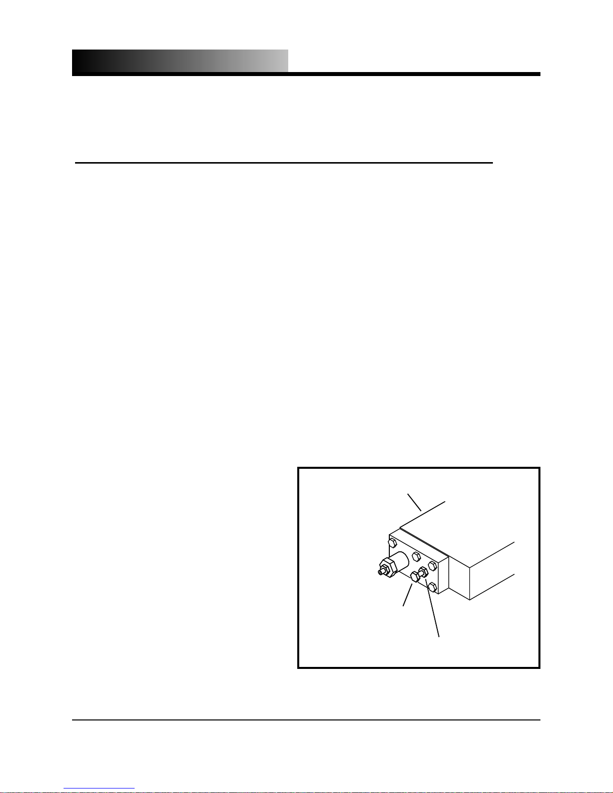
HYDRAULIC PUMP
CONTROL BODY
turning it by hand until it makes contact with the internal compensation
spool.
5. Turn the adjustment bolt 1/4 turn
clockwise, slightly compressing the
compensation spool.
6. Hold the adjustment screw to prevent
it from turning and tighten the lock-
PRESSURE COMPENSATOR
ADJUSTMENT BOLT
PRESSURE COMPENSATOR
ADJUSTMENT BOLT LOCKNUT
nut.
6.1
Figure 6.1 - High-Low Pressure
Compensator Adjustment
Page 57
REPAIR & ADJUSTMENTS
MINIMUM VOLUME CONTROL ADJUSTMENT
The minimum volume control provides an adjustable minimum hydraulic pump volume
regardless of hydraulic system pressure. The minimum volume control is preset at the
factory but may need to be adjusted, particularly after pump repair or replacement or if
supply voltage is not 60 Hz. The minimum volume control must be adjus ted properly to
provide satisfactory pump operation.
1. Disconnect electrical power and fol low your company’s lock out and tag out safety
procedures.
2. Open the electrical control panel and attach an amp meter to one leg of the voltage
supply wiring above the contactor
USE EXTREME CAUTION WHEN ELECTRICAL
POWER IS TURNED ON AND THE ELECTRICAL
PANEL IS OPEN. CONTACT WITH ELECTRICAL
CIRCUITS CAN CAUSE DEATH!
DANGER
3. Turn on the electrical power to the
pelletizer.
4. Begin operati on according to the procedure found on page 4.2.
5. Monitor the amp meter while the pelletizer makes dry ice. The amp reading should peak at the amputating
which corresponds to the machine
voltage as indicated on the motor data
plate. If the amp reading is too high
or too low proceed to the next step.
6. Using a 3/4” wrench, loosen the minimum volume control locknut by turning it counterclockwise.
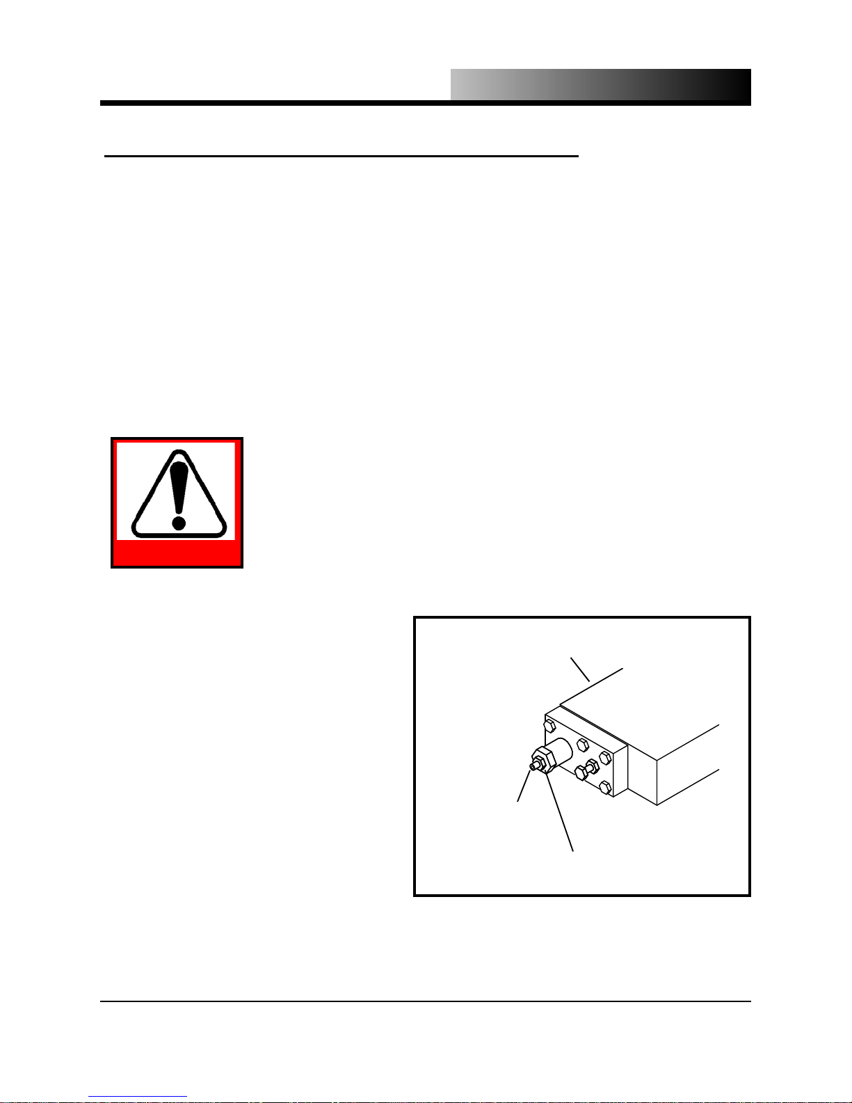
MINIMUM VOLUME
CONTROL ADJUSTMENT BOLT
Figure 6.2 - Minimum Volume Control Adjustment
HYDRAULIC PUMP
CONTROL BODY
MINIMUM VOLUME CONTROL
ADJUSTMENT BOLT LOCKNUT
6.2
Page 58

REPAIR & ADJUSTMENTS
7. Using a 1/4” a l len wrench, adjust the minimum volume control adjusting screw.
Turn the screw clockwise to increase the amp reading or counterclockwise to decrease the amp reading. Make adjustments in 1/4 turn increments.
8. Use the allen wrench to prevent the adjustment screw from turning and tighten the
locknut.
9. Allow the pelletizer to operate normally for approximately one hour and check the
load amperage again. If necessary readjust the minimum volume control.
10.Stop the pelletizer operation and lock out electrical power to the pelletizer.
11.Disconnect the amp meter and close the electrical panel.
High Capacity Hydraulic Unit Set-up & Operation
Note: The following applies to tandem pump units only.
The hydraulic unit has a tandem Oilgear pump as sembly driven at 1800 RPM by a 50
HP electric motor. One Oilgear pump delivers approx. 60 gallons of fluid per minute
and has a two pressure compensating control device. The other pump has a control device that lets you shift from an adjustable high flow set point (approx. 25 GPM) to an
adjustable low flow set point (appro x. 18 GPM) simply by energizing a solenoid control.
The hydraulic unit has electric solenoid operated directional control valves and electric
solenoid operated decompression excess flow and dump valves.
The hydraulic unit has a return line heat exchanger (air-cooled) and return line contamination filter.
Set-up The pump closest to the electric motor is the 60 gal high volume low pressure
compensating pump and is referenced as pump #1. The other pump (farthest from the
electric motor) is the solenoid controlled two volume (adjustable fixed displacement)
pump and is referenced as pump #2.
1. Before starting the unit: (a) The adjustment screw on the max-v olume control of
6.3
Page 59

REPAIR & ADJUSTMENTS
pump #2 should be adjus ted where approx. inch of adjustment screw threads are exposed outside of the jam nut when the jam nut is locked in place (the max-volume
control adjustment is the one closest to the reservoir) and (b) The adjustment screw
of the min- volume control of pump #2 should be adjusted where approx. inch of
adjustment screw threads are exposed outside of the jam nut when the jam nut is
locked in place. (The min-volume adjustment is on the opposite side of the pump
controller from the max- volume control).
2. Start the hydraulic unit and remove control relay CR10 from its relay base.
(Removing CR10 will close the bypass valve.)
3. Adjust the pump #1 compensator adjustment screw (hex head bolt on side of compensator) inward and watch gauge #11 for increasing pressure. When you determine
that the pump pressure is responding to your adjust ment you need to turn the adjustment screw counterclockwise until you have lowered the pressure to 450 PSI and
set the jam nut in place.
Note: Gauge #11 is located adjacent to the discharge port of pump #1
4. Use the manual override and energize control relay CR 16 that will activate the pump
#1 solenoid control val ve. While control relay CR16 is energized, adjust the pump
pressure control valve (located on the pump #1 controller) either clockwise to in
crease or counter clockwise to decrease until the pressure reading on gauge #11 is
650-700 PSI. Lock the jam nut.
5. Loosen the jam nut on the system relief valve (located in the subplate supporting
valve #28). Using the manual override, energize control relay CR17 and keep it energized while you adjust the system relief valve (clockwise to raise or counter
clockwise to lower) to a pressure setting of 2900 PSI.
Note: You can observe system pressure on gauge #23 located next to the pressure
switches mounted on the upper right end of the reservoir.
6. With the system pressure gauge holding 2900 PSI, loosen the lock screw on the pressure switches and adjust the switches to the setting where the contacts will make on
rising pressure at 2900 PSI and lock the setting. (You may want to raise and lower
6.4
Page 60

REPAIR & ADJUSTMENTS
the relief valve to simulate rising pressure.)
7. After you have set the pressure switches you should adjust the relief valve clock
wise until the relief setting is reading 3600-3800 PSI on gauge #23. Lock the relief valve jam nut and release control relay CR17.
8. Reset the min-volume adjustment to a position where approx. inches of adjustment screw threads are exposed outside the jam nut when the jam nut is locked
in place.
Note: Shifting the pump #2 swashplate to max-volume setting by overriding control
relay CR17 while you are adjusting the min-volume adjustment provides easier
turning of the adjustment screw.
Replace control relay CR10 into its base.
The final adjustment (if necessary) on the maximum flow and minimum flow of
pump #2 are made by reviewing the actual amp load on the electric motor when the
cylinder is extruding ice. (The max full load amps is 60)
A. If the amp reading exceeds 60 amps when the pressure gauge is climbing from
650 PSI to 2800 PSI during the extrude cycle then the max-volume control
needs to be adjusted inward to decrease the pump flow to an amount where
the amp reading is less than 60 amps.
Likewise if the amp load measures considerably less than 60 amps when the controller shifts at 2900 PSI then the max-volume adjustment screw could be backed out to
increase the pump flow. (The ideal circumstance is to draw exactly 60 amps when
the pump pressure reaches the shift point of 2900 PSI.)
Note: Remember the max-volume adjustment screw can be adjusted much easier
when the pump is shifted to min-vol ume operation.
B. When the pressure switch reaches 2900 PSI and shifts pump #2 to the min-
volume position you will see a significant drop in amp draw on the ammeter.
Then you will see an increase to a peak amp load and then possibly a minimal
drop off before the cylinder reaches the end of stroke. The ideal circumstance
6.5
Page 61

REPAIR & ADJUSTMENTS
is to set the min-volume adjustment for the maximum flow without peaking
over 60 amps.
You will adjust the min-vol ume screw clockwise to increase the minimum flow
which will increase the amp load and raise the peak amp reading on the ammeter. If
the peak amp draw is above 60 amps as a result of the initial setting or your adjustment attempt then you can easily lower the setting by turning the minimum volume
adjustment screw counter clockwise.
Note: The minimum volume adjustment screw turns much easier when CR17 is en ergized and the pump is shifted to max-volume.
Operation
1. When the operation controls are set in automatic operation and "A" cylinder, "B"
cylinder or "Both" cylinders have been selected for operation. The cycle is initiated by pushing the "start butt on".
2. The directional control valve #20 will energize and shift to extend the cylinder.
The cylinder will begin advancing because:
A. Pump #1 shifts to full flow (60 GPM)
B. Pump #2 shifts to high flow (25 GPM)
C. Dump valve #28 closes (time delay)
D. Valve #26 (decompression/excess flow) is off
3. As the cylinder advances the resistance created by the C02 gas being compressed
and the snow packing will cause the system pressure to raise to 650-700 PSI then
pump #1 (60 GPM) compensates to a no flow condition and pump #2 (25 GPM)
high flow setting is advancing the cylinder until it reaches 2900 PSI and the
pump #2 pressure switch trips and shifts the pump #2 volume setting to minvolume (18 GPM) and also shifts the pump #1 solenoid control to 450 PSI
(unload pressure).
6.6
Page 62

REPAIR & ADJUSTMENTS
4. When the pressure switch shifts at 2900 PSI the cylinder continues to advance at an
18 GPM flow rate and the pressure increases (due to ice compression resistance) to
approx. 3200-3600 PSI. The ice slug moves and extrudes ice through the die until
the end of stroke limit switch (extend) is tripped.
Note: The pressure drops off slightly when the ice slug begins to move.
5. When the cylinder reaches the end of the extend stroke and signals the processor
(end of stroke limit switch), the following happens:
A. Valve #26 shifts to decompression and valve #28 opens to decompress the system
pressure.
B. Valve #20 directional control de-energizes and shifts from extend to the center
position (all ports closed).
C. The cylinder stops its advance travel.
6. Direction control valve #20 energi zes and shifts to retract the cylinder. The cylinder
will begin retracting because:
A. Pump #1 shifts to full flow (60 GPM)
B. Pump #2 shifts to full flow (25 GPM)
C. Dump valve #28 closes
D. Valve #26 shifts from decompression to excess flow position.
7. When the cylinder has traveled to a point near the full retracted position it trips a retracted limit switch, and the following happens:
A. Pump #2 shifts to min-volume (18 GPM)
B. Pump #1 shifts to the 450 PSI (unload) setting
C. Valve #28 is energized and dumps partial pump flow to tank
6.7
Page 63

REPAIR & ADJUSTMENTS
D. Directional valve #20 de-energizes and shifts to the center position (all ports
closed) stopping the cylinder travel.
8. Valve #26 shifts to the center blocked position from the excess flow position
(time delay following the stopping of the cylinder).
9. Cycle starts over
Valve Operation Status
1. Valve #28 (by-pass valve)
A. By-pass valve #28 is energized and open to reservoir anytime the system is in
manual operation and the cylinder directional valves #20 are in the center position (no cylinder movement).
B. By-pass valve #28 is energized a nd open to reservoir for two (2) seconds
when the hydraulic unit starts-up.
C. By-pass valve #28 is energized and open to reservoir when the system is in
automatic and both cylinders are retracted on the home limit switch.
D. By-pass valve #28 is energized and open to reservoir when valve #26 is
shifted to the decompression position.
E. By-pass valve #28 is energized and open for 100 mil/sec when "A" or "B" re-
tracting cylinder hits the retracted limit switch.
F. By-pass valve #28 is energized and o pen to reservoir when "A" or "B" ex-
tending cylinder hits the extend limit swit ch and turns off 200 mil/sec after
valve #20 (cylinder directional valve) shifts to the retract position.
2. Valve #26 (decompression)
Valve #26 is shifted to the decompression position whenever an extending cylinder
hits the extend limit switch then closes 200 mil/sec after valve #20 (cylinder di rectional valve) shifts to retract position.
6.8
Page 64

REPAIR & ADJUSTMENTS
3. Valve #26 (excess flow)
Valve #26 is energized and shifted to the excess flow position 200 microseconds after
valve 20 is shifted to the retract travel position.
Dry Ice Extrusion Process (start-up)
Note: When the cycle start is activated the microprocessor will determine if “A” cylinder has been selected, "B" cylinder has been selected or "Both" cylinders have been selected to operate.
1. If "A" or "A&B" have been selected for an operation mode the first function will be
a clean out stroke on "A" (then a clean out stroke on "B"' if A&B were selected).
2. If "B"' had been selected then a cl ean out stroke on cylinder "B" is the only function.
Note: Clean out stroke consists of injection of C0
w/valve #2 for a preset injection
2
time then check for ice plug by sensing pressure on PS-1
3. If PS-1 senses pressure on clean out stroke, then the sequence shifts to normal operation.
4. If PS-1 does not sense pressure due to the presence of an ice plug. The machine goes
into a series of five (5) cool down cycles.
A. #1 inject CO
B. #2 inject C0
, with valve #3 for 1 minute (extrude and return)
2
with valve #3 f o r 1 m inute (extru de and return)
2
C. #3 inject C02 with val v e #3 for 1 minute (extrude an d return)
D. #4 inject C02 with valve #3 for 1 minute (extrude and return)
E. #5 inject C02 with valve #3 for 1 minute (extrude and return)
5. Inject C02 with valve #2 and check for plug (pressure switch PS-1)
A. If PS-1 senses pressure the sequence will shift to normal operation.
6.9
Page 65

REPAIR & ADJUSTMENTS
B. If PS-1 does not sense pressure return to cool down cycle #5 of 5
C. The machine checks for a plug again (start of step 5)
D. Repeat (up to 15 cycles) #5 of 5
1) If plug is present, go to normal cycle
2) If no plug is indicated after 15 cycles, the unit will shut down.
6.10
Page 66

Page 67

SECTION
7
APPENDIX
7.0
Page 68

APPENDIX
GLOSSARY
Carbon Dioxide The chemical compound formed by combining one atom of
carbon with two atoms of oxygen
CO
The molecular formula for carbon dioxide
2
Critical Point The temperature and pressure above which a chemical
compound can only exist as a supercritical fluid - for Carbon
Dioxide: 87.9 ºF (31.1 ºC) and 1070.6 psig (73.8 bar)
Dew Point The temperature at which water dissolved in carbon dioxide
condenses
Dry Ice Solid carbon dioxide
Sublime To change from a solid to a vapor without becoming a liquid
Supercritical Fluid A chemical compound at temperature and pressure greater than
its critical point
Triple Point The conditions at which all three states (solid, liquid and vapor)
of some chemical compounds can exist at equilibrium. For
Carbon Dioxide the conditions are: -69.9 ºF (-56.6 ºC) and
60.4 psig (4.2 bar)
7.1
Page 69

REFERENCES
Compressed Gas Association
1725 Jefferson Davis Hwy.
Suite 1004
Arlington, VA 22202-4102 USA
Phone: (703) 412-0900
APPENDIX
7.2
Page 70

APPENDIX
All equipment manufactured and sold by Tomco
against defects in materials and workmanship (normal wear and tear excluded) under normal use and service for a period of
one year from the date of invoice or hour usage for the following equipment:
LIMITED WARRANTY
Equipment Company, hereinafter identified as TOMCO2, shall be warranted
2
Pelletizer/Extruder/Disc Press 2,000 hours
AH-45/CM-40 Pump 2,000 hours
CO
Cleaning System 15,000 cycles or about 2,000 hours
2
This Limited Warranty shall be invalidated if the products:
a) have not been installed, handled, or used in accordance with TOMCO
’s recommended procedures.
2
b) have been damaged through the negligence or abuse of the customer or any subsequent purchaser.
c) are damaged by causes external to the products, including (without limitation) shipping damage, or
accident or catastrophe of nature.
d) have been subjected to repairs or attempted repairs by any person other than an authorized TOM-
CO
service technician.
2
e) have been repaired using non-TOMCO
spare parts.
2
The limit of TOMCO
part of such equipment, which TOMCO
’s entire warranty obligation is, at TOMCO2’s election, replacing, issuing credit or repairing any covered
2
’s examination determines to be defective. These remedies are exclusive and are the
2
sole measure of recoverable damage.
A claim must be made within 30 days after the defect is discovered and any claim not made within the specified time period
may be deemed by TOMCO
to be waived or released by purchaser.
2
Defective part(s) must be returned to TOMCO
ranty consideration. Upon receipt of the defective part, TOMCO
within 20 days upon receipt of replacement part to receive vali d war-
2
will make a warranty determination in accordance
2
with our limited warranty and notify purchaser in the event parts are not covered.
Prior to returning any part to TOMCO
Parts and Service Department. Parts must be returned to TOMCO
, a returned goods authorization number (RGA) must be obtained from the
2
Equipment Company at 3340 Rosebud Road, Lo-
2
ganville, Georgia 30052, with the transportation charges prepaid and the following information provided:
a) Company name
b) Company address
c) Contact name
d) Contact telephone number
e) Quantity, description, model number and, if applicable, a serial number of each item being returned
f) Reason for return
g) Original TOMCO
sales order number, invoice number or customer purchase order number
2
h) Return goods authorization number (RGA) must appear on the shipping label and packing slip
TOMCO
harm to others or loss of profits. Neither TOMCO
shall not be liable for consequential damages or any special, incidental, or other cost, expense or damage, including
2
nor purchaser shall seek, from the other, reimbursement or indemnity for
2
claims related to the equipment that involves its employees or its visitors.
THIS IS THE ONLY WARRANTY GIVEN BY TOMCO
HEREIN; TOMCO
DISCLAIMS ALL OTHER WARRANTIES, EXCEPT TITLE, INCLUDING ANY WARRANTY
2
EQUIPMENT COMPANY, EXCEPT AS PROVIDED
2
OF MERCHANTABILITY OR FITNESS FOR A PARTICULAR PURPOSE.
This warranty excludes products, accessories, parts or attachments that are not manufactured by TOMCO
of the warranty from the original manufacturer assigned by TOMCO
request of TOMCO
.
2
. Copies of such applicable warranties are available upon
2
except to the extent
2
Revised 1-28-02
7.3
Page 71
APPENDIX
REPLACEMENT PARTS & ORDERING INFORMATION
QTY PART NUMBER DESCRIPTION
1 267302 Filter Screen, 1 1/2” x 6” (38.1 mm x 152.4 mm)
2 328703 Piston Wearband
2 3328-2 Rod Seal
2 3329-2 Rod Bearing
2 3320-4 Hydraulic Cylinder Rebuild Kit
1 318593 Hydraulic Fluid Filter
1 3284-7 Compression Cylinder Piston
2 2043-A1 1/2” Injection Ball Valve
1 2040 Injection Ball Valve Actuator
1 1080-91 Limit Switch
2 3686 Compression Cylinder Pressure Switch
2 3197 Compression Cylinder Pressure Gauge, 0 - 100 psig
1 3192 Hydraulic Pressure Gauge, 0 - 5000 psig
2 3317 Hydraulic Directional Valve Coil
2 3318 Hydraulic Valve Rectifier
2 3747 Delay or Injection Timer
3 3735-1 120V Panel Bulb
1 3336012 Hydraulic Relief Cartridge
Table 7.1.1 - Replacement Parts for Model DE89RB-100-US
7.4
Page 72
APPENDIX
QTY PART NUMBER DESCRIPTION
2 267302 Filter Screen, 1 1/2” x 6” (38.1 mm x 152.4 mm)
4 328713 Piston Wearband
2 3328-2 Rod Seal
2 3329-2 Rod Bearing
2 3320-4 Hydraulic Cylinder Rebuild Kit
1 318593 Hydraulic Fluid Filter
1 3284-7 Compression Cylinder Piston
2 2043-A 1/2” Injection Ball Valve
1 2040 Injection Ball Valve Actuator
1 1080-91 Limit Switch
2 3686 Compression Cylinder Pressure Switch
2 3197 Compression Cylinder Pressure Gauge, 0 - 100 psig
1 3192 Hydraulic Pressure Gauge, 0 - 5000 psig
2 3317 Hydraulic Directional Valve Coil
2 3318 Hydraulic Valve Rectifier
2 3747 Delay or Injection Timer
3 3735-1 120V Panel Bulb
1 3336012 Hydraulic Relief Cartridge
Table 7.1.2 - Replacement Parts for Model HP-200
7.5
Page 73
QTY PART NUMBER DESCRIPTION
1 267303 Filter Screen, 3 1/2” x 10” (88.9 mm x 254 mm)
2 328711 Piston Wearband
1 3325 Rod Seal
1 3327 Rod Bearing
1 3320-6 Hydraulic Cylinder Rebuild Kit
1 318593 Hydraulic Fluid Filter
1 3286 Compression Cylinder Piston
1 2043-A 1/2” Injection Ball Valve
1 2040 Injection Ball Valve Actuator
1 1080-91 Limit Switch
2 3686 Compression Cylinder Pressure Switch
2 3197 Compression Cylinder Pressure Gauge, 0 - 100 psig
1 3192 Hydraulic Pressure Gauge, 0 - 5000 psig
APPENDIX
2 3317 Hydraulic Directional Valve Coil
2 3318 Hydraulic Valve Rectifier
2 3747 Delay or Injection Timer
3 3735-1 120V Panel Bulb
1 3336012 Hydraulic Relief Cartridge
1 3250-1 Air Valve
Table 7.1.3 - Replacement Parts for Model DE89RB-500
7.6
Page 74
APPENDIX
QTY PART NUMBER DESCRIPTION
1 267303 Filter Screen, 3 1/2” x 10” (88.9 mm x 254 mm)
2 328711 Piston Wearband
1 3325 Rod Seal
1 3327 Rod Bearing
1 3320-8 Hydraulic Cylinder Rebuild Kit
1 318593 Hydraulic Fluid Filter
1 3286 Compression Cylinder Piston
1 2043-A 1/2” Injection Ball Valve
1 2040 Injection Ball Valve Actuator
1 1080-91 Limit Switch
2 3686 Compression Cylinder Pressure Switch
2 3197 Compression Cylinder Pressure Gauge, 0 - 100 psig
1 3192 Hydraulic Pressure Gauge, 0 - 5000 psig
2 3317 Hydraulic Directional Valve Coil
2 3318 Hydraulic Valve Rectifier
2 3747 Delay or Injection Timer
3 3735-1 120V Panel Bulb
1 3336012 Hydraulic Relief Cartridge
1 3250-1 Air Valve
Table 7.1.4 - Replacement Parts for Model HP-500
7.7
Page 75
QTY PART NUMBER DESCRIPTION
2 267303 Filter Screen, 3 1/2” x 10” (88.9 mm x 254 mm)
4 328711 Piston Wearband
2 3325 Rod Seal
2 3327 Rod Bearing
2 3320-6 Hydraulic Cylinder Rebuild Kit
1 318593 Hydraulic Fluid Filter
1 3286 Compression Cylinder Piston
2 2043-A 1/2” Injection Ball Valve
1 2040 Injection Ball Valve Actuator
1 1080-91 Limit Switch
2 3686 Compression Cylinder Pressure Switch
2 3197 Compression Cylinder Pressure Gauge, 0 - 100 psig
1 3192 Hydraulic Pressure Gauge, 0 - 5000 psig
APPENDIX
2 3317 Hydraulic Directional Valve Coil
2 3318 Hydraulic Valve Rectifier
2 3747 Delay or Injection Timer
3 3735-1 120V Panel Bulb
1 3336012 Hydraulic Relief Cartridge
1 3250-1 Air Valve
Table 7.1.5 - Replacement Parts for Model DE89RB-1000
7.8
Page 76
APPENDIX
QTY PART NUMBER DESCRIPTION
2 267303 Filter Screen, 3 1/2” x 10” (88.9 mm x 254 mm)
4 328711 Piston Wearband
2 3325 Rod Seal
2 3327 Rod Bearing
2 3320-8 Hydraulic Cylinder Rebuild Kit
1 318593 Hydraulic Fluid Filter
1 3286 Compression Cylinder Piston
2 2043-A 1/2” Injection Ball Valve
1 2040 Injection Ball Valve Actuator
1 1080-91 Limit Switch
2 3686 Compression Cylinder Pressure Switch
2 3197 Compression Cylinder Pressure Gauge, 0 - 100 psig
1 3192 Hydraulic Pressure Gauge, 0 - 5000 psig
2 3317 Hydraulic Directional Valve Coil
2 3318 Hydraulic Valve Rectifier
2 3747 Delay or Injection Timer
3 3735-1 120V Panel Bulb
1 3336012 Hydraulic Relief Cartridge
1 3250-1 Air Valve
Table 7.1.6 - Replacement Parts for Model HP-1000
7.9
Page 77
QTY PART NUMBER DESCRIPTION
2 267303 Filter Screen, 3 1/2” x 10” (88.9 mm x 254 mm)
4 328712 Piston Wearband
2 3325 Rod Seal
2 3327 Rod Bearing
2 3320-7 Hydraulic Cylinder Rebuild Kit
1 318593 Hydraulic Fluid Filter
1 3286-7 Compression Cylinder Piston
2 2043-A 1/2” Injection Ball Valve
1 2040 Injection Ball Valve Actuator
1 1080-91 Limit Switch
2 3686 Compression Cylinder Pressure Switch
2 3197 Compression Cylinder Pressure Gauge, 0 - 100 psig
1 3193 Hydraulic Pressure Gauge, 0 - 5000 psig
APPENDIX
2 3317 Hydraulic Directional Valve Coil
2 3318 Hydraulic Valve Rectifier
2 3747 Delay or Injection Timer
3 3735-1 120V Panel Bulb
1 3336012 Hydraulic Relief Cartridge
1 3250-1 Air Valve
Table 7.1.7 - Replacement Parts for Model DE89RB-1500
7.10
Page 78
APPENDIX
QTY PART NUMBER DESCRIPTION
2 267302 Filter Screen, 1 1/2” x 6” (38.1 mm x 152.4 mm)
4 328713 Piston Wearband
2 3328-2 Rod Seal
2 3329-2 3 1/4” (82.55 mm) Rod Bearing
2 3329 1 3/4” (44.45 mm) Rod Bearing
2 3320-4 Hydraulic Cylinder Rebuild Kit
1 318593 Hydraulic Fluid Filter
1 328020 1/2” Forming Cylinder Wearband
1 3113-SK Forming Cylinder Seal Kit
1 3112-RB Slide Gate Rod Bearing
1 3112-SK Slide Gate Seal Kit
1 3284-7 Compression Cylinder Piston
1 2056 CO2 Injection Needle Valve
2 2043-A 1/2” Injection Ball Valve
1 2040 Injection Ball Valve Actuator
1 1080-91 Limit Switch
2 3686 Compression Cylinder Pressure Switch
2 3197 Compression Cylinder Pressure Gauge, 0 - 100 psig
1 3192 Hydraulic Pressure Gauge, 0 - 5000 psig
2 3317 Hydraulic Directional Valve Coil
2 3318 Hydraulic Valve Rectifier
2 3747 Delay or Injection Timer
3 3735-1 120V Panel Bulb
1 3336012 Hydraulic Relief Cartridge
1 3336-011 Forming Cylinder Relief Cartridge
1 3783 Proximity Limit Switch
1 3320-1 NC Decompression Valve Cartridge & Coil
Table 7.1.8 - Replacement Parts for Model LB-450
7.11
Page 79
QTY PART NUMBER DESCRIPTION
Cold end seal kit
Hydraulic cylinder seal kit
3293075 Dies, 3/4” pellet standard
1080-91 Limit Switch
Piston Sleeve
Hydraulic Oil Filter
Filter Screen
Vent Box
Filter Screen Retainer
Filter Screen O-ring
1/4-20X1 1/2” SS SHCS
1/4-20X1 1/8” SS SHCS
3735-1 120V Panel Bulb
APPENDIX
1/2” Gemini Ball Valve (standard)
1/4” Gemini Ball Valve
1/2” Bürkert Valve
3197 0-100 psi gauge
3192 0-5000psi gauge
Hydraulic Directional Valve Coil
Hydraulic Valve Rectifier
Hydraulic Relief Cartridge
Compression Cylinder Pressure Switch
3747 Delay Timer
Die Bolt Kit
Cold End Tie Rod Kit
Table 7.1.9 - Replacement Parts for 8” High Capacity
7.12
Page 80

APPENDIX
You can contact TOMCO2 EQUIPMENT CO. for parts and service 24 hours a day, 7
days a week at:
TOMCO
EQUIPMENT COMPANY
2
3340 Rosebud Road
Loganville , G eorgia 30052 USA
Telephone
(770) 979-8000 · Toll Free in the U.S. (800) 832-4262
Fax
(770) 985-9179
Parts & Service Fax
(770) 979-2514
E-Mail
Internet
http://www.tomcoequipment.com
7.13
Page 81

NOTES
APPENDIX
7.14
Page 82

APPENDIX
NOTES
7.15
Page 83

APPENDIX
CUSTOMER QUESTIONNAIRE
Name
Company
Phone
Application
1. How did you receive this manual? Was the manual . . .
a. Included in a product shipment? d. Give n to you by a colleague?
b. Given to you by management? e. Other?
c. Purchased by you?
2. How frequently do you use this manual?
a. Quarterly d. Daily
b. Monthly e. Hourly
c. Weekly f. Seldom
3. Under what circumstances do you use this manual?
4. Describe the last time you used this manual.
5. What task or project were you performing when you used this manual?
Date
Please Complete and Mail to:
TOMCO
Engineering Department
3340 Rosebud Rd.
Loganville, GA 30052 USA
or fax to:
(770) 985-9179
EQUIPMENT COMPANY
2
6. How do you use this manual? Do you . . .
a. Sit down and read it?
b. Refer to a certain section while performing a task or project?
c. Look up information for someone else?
d. Refer to it only when you have a problem to solve?
e. Other?
7. How do you look up information in this manual? Do you . . .
a. Use the table of contents?
b. Fl ip th rough th e pages until you locate the right section?
c. Flip to the tabbed sections, then proceed to locate information?
d. Other?
8. When you use this manual, how easy is it to find information? Do you . . .
a. Always locate the right section immediately?
b. Sometimes turn to another section before you locate the right one?
c. Take more than three times to locate information?
d. Fai l to loc ate information?
9. Do you record notes in the margins of this manual? Yes No
10. If yes, what notes do you write down?
continued on other side
User-Friendliness
7.16
Page 84

APPENDIX
11. Evaluate how descriptive or detailed key manual components are. Complete the following statements
usi ng a 1 to 4 scale. 1 is not descriptive and detailed, 4 is very descriptive and highly detailed.
The headings in this manual were 1 2 3 4
The sub-headings in this manual were 1 2 3 4
The instructions in this manual were 1 2 3 4
The illustrations, graphics in this manual were 1 2 3 4
12. Evaluate the readability of this manual. Complete the following statements by using a 1 to 4 scale. 1 is
hard to read, 4 is very easy to read.
The headings in this manual were 1 2 3 4
The sub-headings in this manual were 1 2 3 4
The instructions in this manual were 1 2 3 4
The illustrations, graphics in this manual were 1 2 3 4
13. Evaluate the accuracy of this manual. Complete the following statements using a 1 to 4 scale. 1 is not accurate, 4 is accurate.
The headings in this manual were 1 2 3 4
The sub-headings in this manual were 1 2 3 4
The instructions in this manual were 1 2 3 4
The illustrations, graphics in this manual were 1 2 3 4
14. What sections, if any, were inaccurate?
15. Who else uses this manual?
16. What do they use it for?
Overall Impression
17. What do you like best about this manual?
Graphics Color Special sections
Illustrations Size Job aids
Format Length Supplemental material
Style Consistency Other
18. What do you like least about this manual?
Graphics Color Special sections
Illustrations Size Job aids
Format Length Supplemental material
Style Consistency Other
19. What would you change about this manual?
20. What sections need to be updated?
21. What was your overall impression of this manual?
7.17
Page 85
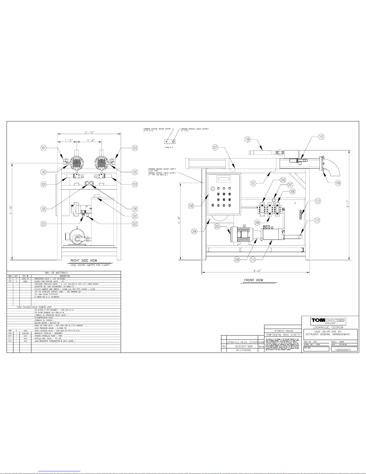
Page 86
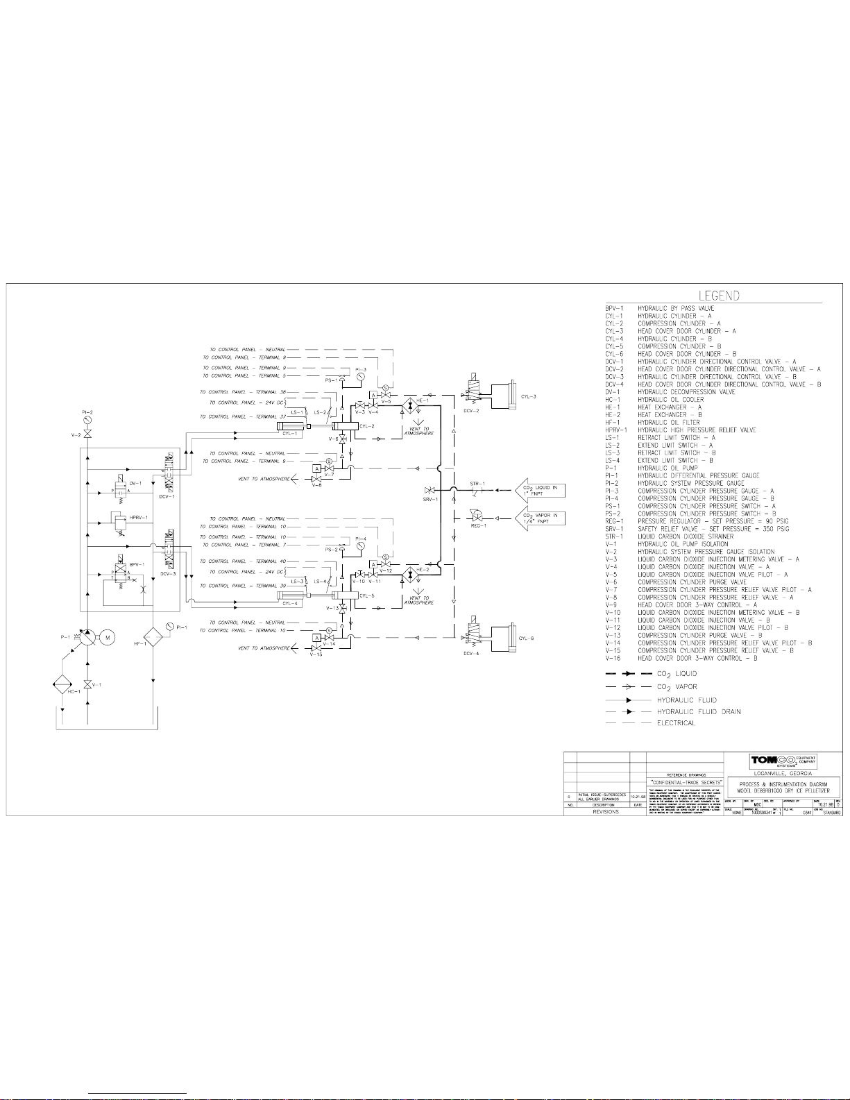
Page 87
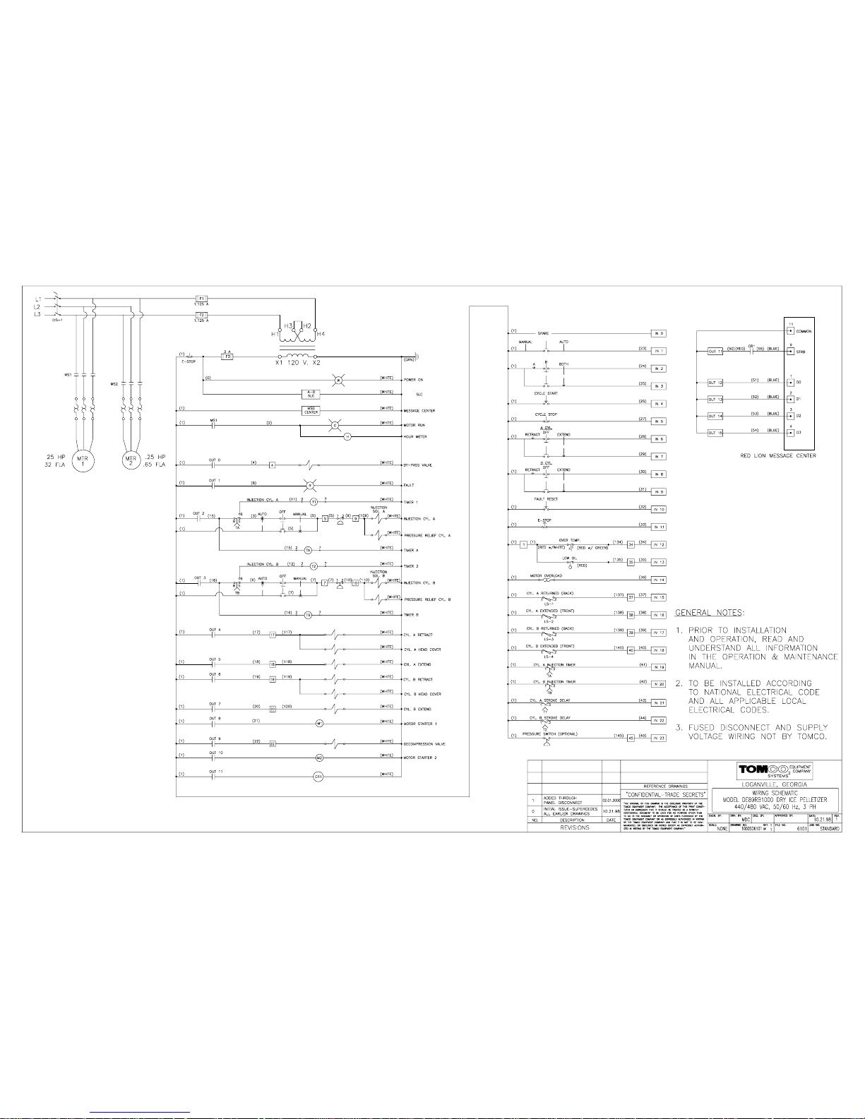
 Loading...