

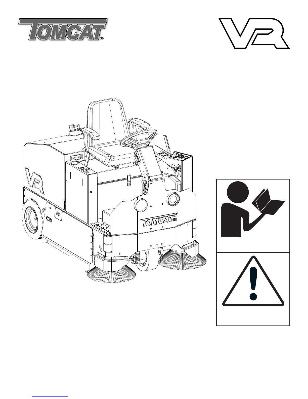
COMMERCIAL CLEANING EQUIPMENT
Operating Instructions (EN)
Read these Instructions before
using the machine.
Read these Safety Messages
before using the machine.
www.tomcatequip.com
1711 South Street
Racine, WI 53404 (USA)
(800) 450-9824 | (+001) 262-681-6470 VERSION 15.246
© 2015 RPS Corporation VR-OP-EN

INTRODUCTION
This manual is furnished with each new machine. This manual will allow the Operator to get the best performance out of
your RPS manufactured Scrubber-Drier, Sweeper, Burnisher, or Orbital Scrubber. Read this manual thoroughly before
operating or servicing the machine.
This machine will provide excellent performance, but the best results will be obtained at the most minimum costs if:
• The machine is regularly maintained - per the machine Preventative Maintenance instructions provided.
• The machine is operated with reasonable care and caution.
• The machine is maintained with manufacturer supplied parts.
ABOUT THIS MANUAL
TABLE OF CONTENTS: Tells you where to look in the manual.
SAFETY MESSAGES: Section contains important information regarding hazard or unsafe practices of the machine. Lev-
els of hazards are identifi ed that could result in product or personal injury, or severe injury resulting in death.
OPERATION CONTROLS / MACHINE COMPONENTS: Shows you the different machine controls and features.
MACHINE SETUP: Tells you how to setup machine from un-crating to installing squeegee and brushes.
MACHINE OPERATION: Section is to familiarize the operator with the operation and function of the machine.
BATTERY CHARGING: Shows you how to charge the batteries (on-board and off board charging).
MAINTENANCE: This section contains preventative maintenance to keep the machine and it’s components in good work-
ing condition. They are listed in this general order:
• Batteries
• Brooms
• Filters
• Service Schedule
• Machine Trouble Shooting
TROUBLE SHOOTING: A list of common problems that may occur.
MACHINE SPECS: Tells you Machine Specifi cations for the various parts of the machine.
MACHINE INSTALL FORM: Should be fi lled out upon machine installation and faxed to 1-866-632-6961 or online at
www.rpscorporation.com.
WARRANTY POLICY: Tells you coverage, exclusions and limitations to warranty.
NOTE: The serial number of your machine is located on the lower half of the Steering Pedestal of the machine.
AS OUR POLICY IS ONE OF CONSTANT IMPROVEMENT - ALL INFORMATION AND
SPECIFICATIONS ARE SUBJECT TO CHANGE WITHOUT NOTICE.
- 2 - TR-OP-EN
SERIAL NUMBER

TABLE OF CONTENTS
Introduction 2
About This Manual 2
Table of Contents 3
Safety Messages 4
Safety Label Locations 6
Operation Controls 7
Operation Controls 8
Operation Controls 9
Machine Components 10
Machine Components 11
Machine Setup 12
Un-Crating Machine: 12
Connecting Batteries: 12
Installing Main Broom: 12
Installing Side Brooms: 13
Adjusting Side Brooms: 13
On-Board Charger 16
On-Board Battery Charging (Optional): 16
Description of LED: 16
Battery Charging 17
External Battery Charging: 17
Battery Maintenance Guide 18
Safety: 18
Inspection and Cleaning: 18
Storage: 18
Watering: 18
Maintenance 19
Daily Maintenance: 19
Weekly Maintenance: 19
Monthly maintenance: 19
Yearly Maintenance: 19
Storing Machine: 19
Checking Battery Specifi c Gravity: 19
VR PM Records 20
Trouble-shooting 22
Machine Specs 23
Machine Operation 13
Pre-Cleaning Checklist: 13
Operating Hints: 13
Sweeping: 14
WET Sweeping: 14
Cleaning Filter: 15
Changing Filter: 15
Empty Hopper: 15
Common Wear Parts 24
Cylindrical Brooms: 24
Side Brooms: 24
Filter Kits: 24
Standard Warranty Policy 25
Machine Install / Warranty Registration 26
TR-OP-EN - 3 -
SAFETY MESSAGES
You will see four kinds of safety reminders in this manual:
DANGER
DANGER indicates a hazardous situation which, if not
avoided, will result in death or serious injury.
WARNING
WARNING indicates a potentially hazardous situation
which, if not avoided, could result in death or serious
injury.
CAUTION
CAUTION indicates a potentially hazardous situation
which, if not avoided, could result in minor or moderate
injury or damage to this machine or nearby objects. CAUTION also can be used to alert against unsafe practices.
NOTICE
NOTICE indicates information considered important, but
not hazard-related. This safety message may be related
to property damage or warranty warnings.
Your safety, and that of others, is very important. Operating this machine safely is an important responsibility.
DO NOT OPERATE THIS MACHINE:
• Unless you are trained and authorized to do so by your RPS Authorized Local Distributor
• Unless you have read and understood this Operator’s Manual
• On surfaces with greater than a 5% grade
• Unless equipped with a functional parking brake
WHEN OPERATING THIS MACHINE:
• Remove loose objects from the fl oor that could be projected from the rotating Brooms
• Keep your hands and feet away from the rotating Brooms
• Do not operate this machine where fl ammable liquids are present
• Use caution when maneuvering
BEFORE LEAVING THE MACHINE:
• Park the machine on a level surface
• Turn the machine off & remove key
• Open battery lid
BEFORE SERVICING THE MACHINE:
• Disconnect the Batteries
DANGER
Explosive hydrogen gas forms when Batteries are
charging. An open fl ame or spark can cause this gas
to explode. Serious personal injury or property damage
could occur. Only charge the Batteries in this machine in
a well ventilated area.
- 4 - TR-OP-EN

WARNING
The Batteries in this machine produce hazardous
voltage which can cause electrical shock, burns and/
or electrocution. Always disconnect Batteries before
servicing this machine.
WARNING
When climbing or descending ramps, always drive
machine forward. To avoid overturning the machine, Do
not back down ramps. Do not drive across inclines. Do
not turn while ascending or descending ramps. Overturning the machine can cause serious injury or death.
WARNING
Do not park this machine on ramps or slopes. Always
park this machine on a level, hard surface. Do not operate this machine outdoors or on uneven surfaces.
WARNING
The Batteries in this machine contain sulfuric acid,
which causes burns to skin. If battery acid contacts
clothing or skin, rinse the effected area with cold water
immediately. If battery acid gets on your face or in your
eyes, fl ush the area immediately with cold water and
seek medical attention.
WARNING
Do not remove, paint over or destroy warning decals. If
warning decals become damaged, call 1-262-681-3583
for free replacements.
WARNING
Dress safely. Do not wear a neck tie, scarf, or any
loose or dangling clothing while operating this machine.
Loose or dangling clothing or neck-wear can tangle in
rotating parts, causing serious injury or death.
WARNING
Always turn off this machine before leaving it unattended. Do not allow untrained persons to operate this
machine.
WARNING
NO RIDERS. Do not carry passengers on this machine. Do not use this machine as a stepladder or work
platform.
WARNING
Understand the dynamic braking system before you
operate the machine on ramps. 5 Degree max.
WARNING
To avoid electrical shock, do not operate this machine
over electrical fl oor outlets.
WARNING
Dress safely. Do not wear rings or metal wrist watches
when servicing this machine, as they can cause an
electrical short circuit which can cause serious burns.
CAUTION
Do not operate this machine if any parts have been
damaged or removed.
CAUTION
Always use the automatic battery charger provided by
the manufacturer of this machine to charge the Batteries of this machine. It is designed to charge the Batteries at the appropriate rate. If you must use a different
charger, disconnect the Batteries before charging to
avoid damage to the electronic speed controller.
WARNING
Before you service a Battery, always wear face protec-
tion, protective gloves and protective clothing. Battery
acid or battery explosion can cause serious injuries.
CAUTION
To avoid damage to the electronic control components
of this machine, Do not store this machine outdoors. Do
not pressure wash this machine.
TR-OP-EN - 5 -
SAFETY LABEL LOCATIONS
US
E
ON
LY
DISTIL
L
E
D
W
A
TE
R
I
N
TH
E
B
ATTE
R
I
ES.
U
S
E
O
N
LY T
H
E
OEM
CHAR
G
ER
PR
O
VIDED
W
I
TH TH
E
M
A
-
CH
I
N
E.
AL
WA
YS DISC
ON
NECT
T
HE
B
A
T
T
E
RY
B
E
F
OR
E
S
E
RVICI
NG
THE
M
A
C
H
I
N
E.
RE
F
E
R
T
O
M
A
N
U
A
L
O
R
CA
L
L
+
0
1
1-262-
6
8
1-35
83
DANGER
EXPLOSION RISK!
E
XPL
OS
IVE
H
Y
DROGEN GAS
F
ORMS
W
HEN
B
AT
T
E
RI
E
S ARE CHA
R
GIN
G.
AN OP
E
N
FLAME
OR S
PARK
C
AN C
A
USE THIS
GAS
TO
E
X
P
L
OD
E.
ON
LY CH
A
RG
E
THE B
A
TTER
I
ES
I
N
TH
I
S
M
A
-
C
H
IN
E
IN
A WELL
V
E
N
TILATE
D
A
RE
A.
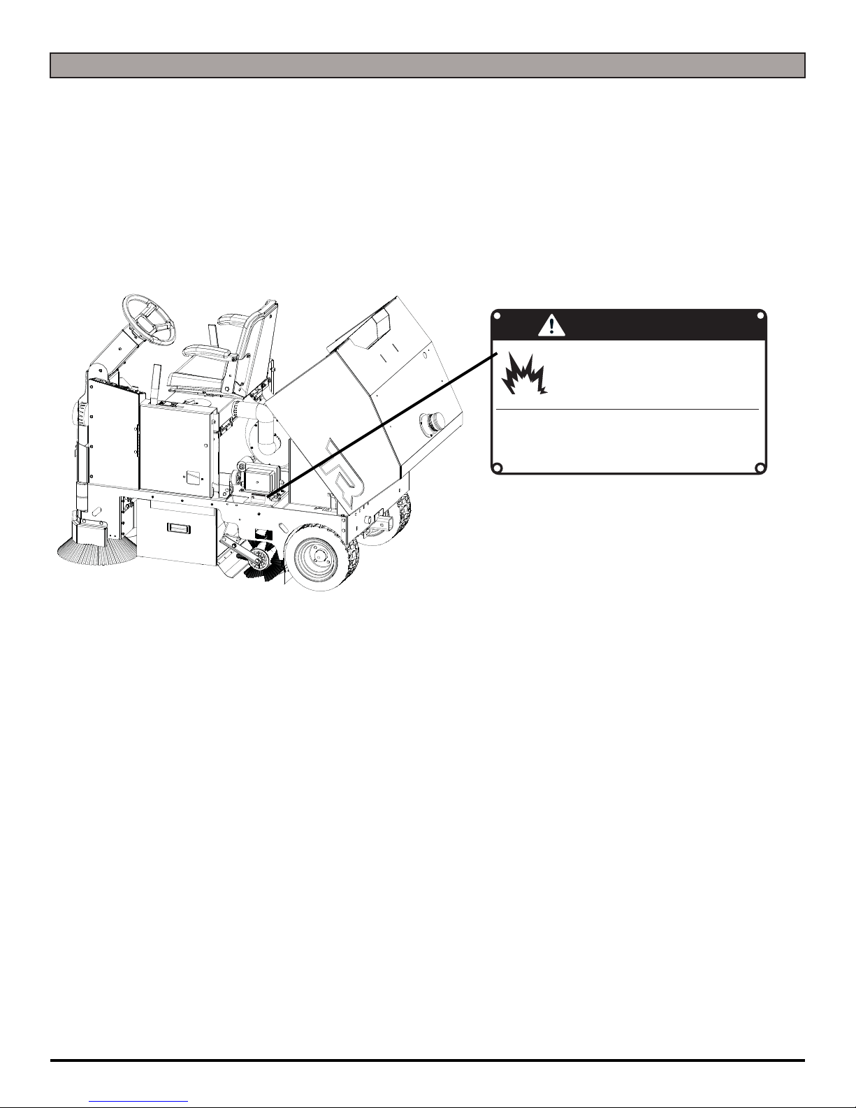
Read and obey all Safety Labels on your VR Floor Sweeper. If you have questions about these labels, ask your supervisor.
These images indicate where on the VR Safety Labels are located. If ever the labels become illegible, worn off, or torn,
promptly report it to your supervisor and replace it.
DANGER
EXPLOSIVE HYDROGEN GAS FORMS WHEN
BATTERIES ARE CHARGING. AN OPEN FLAME
OR SPARK CAN CAUSE THIS GAS TO EXPLODE.
ONLY CHARGE THE BATTERIES IN THIS MACHINE IN A WELL VENTILATED AREA.
USE ONLY DISTILLED WATER IN THE BATTERIES. USE
ONLY THE OEM CHARGER PROVIDED WITH THE MACHINE. ALWAYS DISCONNECT THE BATTERY BEFORE
SERVICING THE MACHINE.
REFER TO MANUAL OR CALL +011-262-681-3583
BATTERY CHARGING LABEL
EXPLOSION RISK!
PART #: 349-7280
- 6 - TR-OP-EN

OPERATION CONTROLS
234
5
1
6
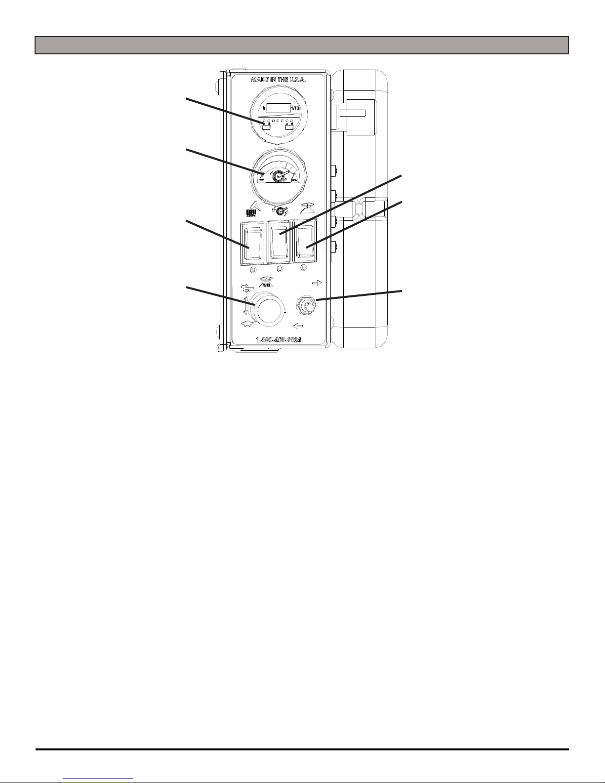
1. CIRCUIT BREAKER: 15 AMP resettable circuit breaker
2. CIRCUIT BREAKER: 15 AMP resettable circuit breaker
3. CIRCUIT BREAKER: 10 AMP Side Broom resettable circuit breaker
4. CIRCUIT BREAKER: 40 AMP Main Broom resettable circuit breaker
5. KEY SWITCH: Turns power of the machine ON and OFF
6. EMERGENCY STOP (OPTIONAL): 1 button push machine shut down in case of emergency
TR-OP-EN - 7 -
OPERATION CONTROLS
4
3
5
6
2
1
1. SIDE BROOM SPEED CONTROL KNOB: Controls the speed of the Side Brooms - Turn
counterclockwise to reduce speed
2. FILTER SHAKER SWITCH: Filter shaker button shakes fi lter to remove dust or debris particles to
deposit into the hopper for removal
3. BRUSH AMP GAUGE: Indicates the amount of amperage that the Main Broom pulling
4. BATTERY GAUGE / HOUR METER: Indicates the amount of batery charge remaining along with
total hours used
5. MAIN BROOM SWITCH: Tuns the Main Broom
ON or OFF
7
6. SIDE BROOM SWITCH: Turns the Side Brooms ON or OFF
7. REVERSE SWITCH: Switch back for reverse machine drive
- 8 - TR-OP-EN
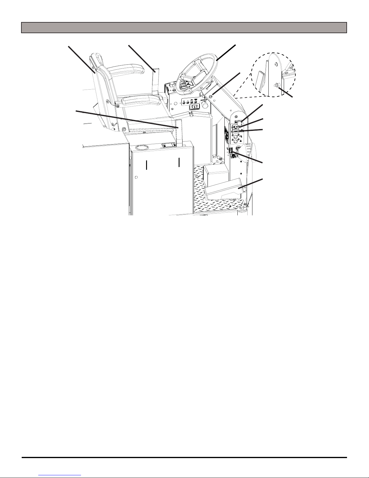
OPERATION CONTROLS
2
3
4
OPPOSITE SIDE OF
STEERING PEDESTAL
5
6
7
1
8
9
10
11
1. SIDE BROOM LIFT LEVER: Lifts and lowers Side Brooms that allow for debris clean up
directly up to walls
2. ADJUSTABLE SEAT WITH ARM RESTS: The machine is equipped with an ergonomic
seat with adjustable arm rests and positioning
3. MAIN BROOM LIFT LEVER: Lifts and lowers the Main Broom
4. STEERING WHEEL: Steers the main Drive Wheel
5. HORN: Sounds the horn for warning oncoming traffi c
6. HEADLIGHT SWITCH: Turns power of the Headlights ON and OFF
7. ADJUSTABLE STEERING: Four settings for operator comfort and ease of entry
8. HOUR METER: Hour meter to indicate complete time machine has been ON
9. RECHARGE CYCLE METER: Shows the amount of charges on a machine
10. CHARGER PORT: Grey 50 used to receive charger input for optional external charger
11. FOOT PEDAL: Controls the acceleration and deceleration of the machine
TR-OP-EN - 9 -

11
MACHINE COMPONENTS
1
6
10
9
8
1. STROBE LIGHT (OPTIONAL): Optional Strobe Light silently alerts others nearby of the
machines presence
2. HEADLIGHTS: Helps you see in low light areas and to warn oncoming traffi c
3. SIDE BROOM GUARDS (OPTIONAL): Optional Side Broom Guards protect your Side
Broom Brushes in case operator error
4. SIDE BROOMS: Allows for debris clean up directly up to walls
6
7
3
4
5
2
3
4
5. FRONT DRIVE TIRE: Drives and steers the machine
6. TIE DOWN POINTS: Location for tie down straps during transport
7. FILTER ACCESS LATCH: Latch holds the Filter Box together while also releasing and
allowing access to the inside of the Filter Box
8. SIDE ACCESS DOOR: Protects the Main Broom and Hopper
9. SIDE DOOR LATCH: Opens and latches closed the Side Access Door to the Main
Broom and Hopper
10. REAR WHEELS: Rear wheels provide three point stability for this machine
11. SIDE BROOM ADJUSTMENT SCREW: Turn screw counterclockwise for fi ne tuning of
height adjustment of the Side Brooms to accommodate for brush wear
- 10 - TR-OP-EN
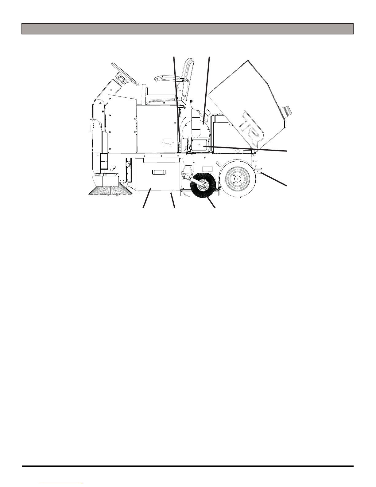
MACHINE COMPONENTS
21
3
4
567
1. FILTER MOTOR: Powers the Beater Bar to clean out the fi lter
2. MAIN BROOM MOTOR: Powers the Main Broom and creates vacuum for the Filter Box
3. ONBOARD CHARGER: Easily charge your machine by conveniently pulling over and
plugging in into any standard wall outlet to charge
4. HITCH (OPTIONAL): Used to attach rear Garbage Can Holder option
5. MAIN BROOM: The powerful Main Broom sweeps the fl oor by sweeping debris into the
back of the Hopper
6. HOPPER TRANSPORT WHEELS: Wheels allow the Hopper to easily slide in and out
from underneath the machine
7. HOPPER: Houses all of the dust and debris that the machine sweeps
TR-OP-EN - 11 -

MACHINE SETUP
UN-CRATING MACHINE:
Carefully check the crate for any signs of damage and that
the batteries are in the unit.
To un-crate the machine, remove banding strips from
around the crate. Take off the top and sides and dispose
properly. Remove brackets from machine wheels.
Remove bolts from pallet, then remove board. Carefully
roll the machine off of the base. Notify the carrier
immediately if concealed damage is discovered.
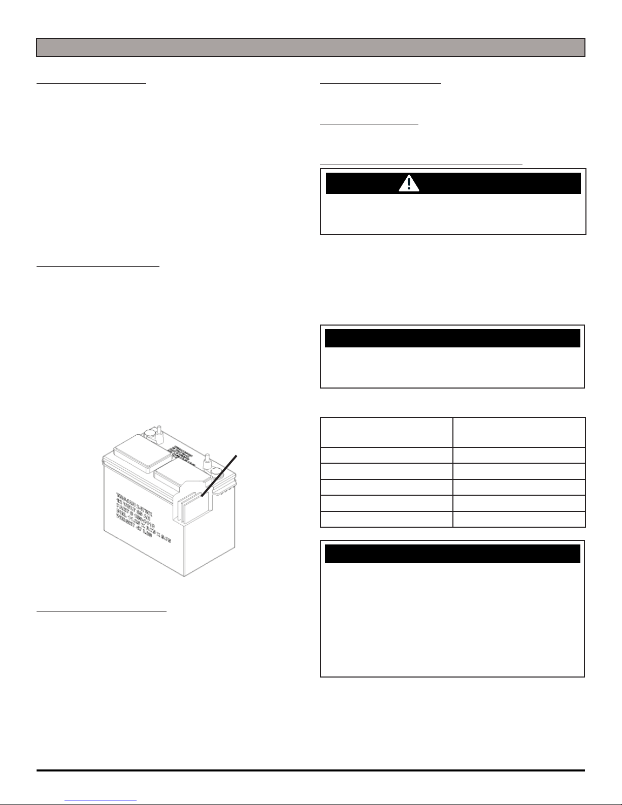
CONNECTING BATTERIES:
Your machine is equipped with (4×) 6-Volt/ 245 AH, (4×)
6-Volt/ 325 AH, or (4×) 6-Volt/ 420 AH Wet Lead Acid,
AGM, Industrial, or Deep Cycle Batteries which form a 24
Volt system.
(SEE PICTURE BELOW OR BATTERY DISCONNECT
LABEL FOR CORRECT CABLE CONNECTIONS)
INSTALLING MAIN BROOM:
1. Turn Key Switch to the OFF position and remove Key.
2. Open Side Access Door and remove bolt holding Idler
Arm in place (A) (SEE BELOW).
A
3. Remove Idler Arm and pull out old Broom (B) (SEE
BELOW).
B
1. Turn all switches to the OFF position and remove Key.
2. Tip Tank back. Attach all Battery Cables to Terminals
as shown below.
3. Turn ON main power switch and check the Battery
Meter to ensure correct installation. Charge Batteries
if needed (SEE BATTERY CHARGING).
NOTICE
Batteries are a possible environmental hazard. Consult
your Battery supplier for safe disposal methods.
NOTICE
Orientation of Batteries is critical for cables to reach.
24 VOLTS
4. Slide the new Broom in. With new Broom on Driver,
spin until Driver engages Broom.
5. Reinstall Idler Arm and tighten bolt (B) (SEE ABOVE).
6. If Broom is not level, loosen bolt and run Main Broom
motor for a couple seconds.
7. Retighten bolt and ensure Broom is level.
NOTICE
For correct Main Broom application - Contact your Local
Servicing Dealer.
DRIVER ALIGNED NOT ALIGNED
- 12 - TR-OP-EN

INSTALLING SIDE BROOMS:
1. Lower the Side Brooms by pulling forward on the Side
Broom Level and sliding to the rear.
MACHINE OPERATION
PRE-CLEANING CHECKLIST:
2. Remove the Side Brooms from the box.
3. Install the Side Brooms onto the Motor Shaft. Use the
bottom hole on the shaft to install the Clevis Pin and
A
Saftey Clip (A) (SEE BELOW).
4. Check Side Broom height to see if Adjustments are
needed.
ADJUSTING SIDE BROOMS:
1. To adjust Side Broom height, turn Adjustment Screws
Clockwise to raise and Counterclockwise to lower (B)
(SEE BELOW).
2. The right Side Broom bristles should contact the fl oor in
a 10 o’clock to a 3 o’clock pattern when the Broom is in
motion (C) (SEE BELOW). The left Side Broom bristles
should contact the fl oor in a 9 o’clock to a 2 o’clock
pattern when the Broom is in motion (D) (SEE BELOW).
B
C
Read and understand the Safety Messages section on Pages 3 and 4 before operating the machine.
1. Check Battery Condition Gauge on the Control Panel.
Make sure Batteries are fully charged before using.
2. Check the condition of the Brooms.
3. Check to make sure Hopper is empty.
4. Disconnect Charger and close Hood.
5. Adjust the Seat and Steering Pedestal.
6. Turn the Key Switch ON and drive to the area to be
cleaned.
7. Adjust the speed of the Side Brooms to the desired
speed and confi rm the Side Brooms height is correct.
8. Lower the Main Broom and the Side Brooms.
9. Drive slowly.
OPERATING HINTS:
1. Observe the amount of dirt/debris that the machine is
sweeping up. If dirt/debris is left on ground make sure
that the Wet Sweep By-Pass is not open. This feature
reduces dust control and should only be used when
operating on a fl oor with water on it.
2. Always operate at lower speeds when sweeping around
walls and objects. You should reduce the speed to maintain control when turning.
D
3. To raise the Side Brooms higher when in the up position,
adjust the Adjustment Arm (E) (SEE BELOW).
E
TR-OP-EN - 13 -
3. Change or turn over Brooms when dirty.
4. Stay clear of objects protruding from the fl oor such as
sockets, grates, etc, for they will damage the Brooms.
5. Always keep an eye on your gauges. They let you know
the status of a particular system at a glance. If your
battery gauge is reading low you must stop immediately
and recharge. Running the Batteries dead will result in
damage to the Batteries.
6. When you are ready to stop, raise the Side Brooms,
raise the Main Broom, turn OFF the Side Broom Switch,
turn OFF the Main Broom Switch and drive the machine
back to the charging area. Be sure to clean the Hopper
thoroughly before storing the machine.

SWEEPING:
1. Turn on machine Key Switch (A).
2. Check the Battery Gauge to ensure proper charge
before starting to sweep (B).
3. Lower the Main Broom to the fl oor by dropping the
Main Broom Lift Lever forward (C).
4. Lower the Side Brooms head to the fl oor by dropping
the Side Broom Lift Lever forward (D).
5. Turn on the Main Broom Motor by pressing the Main
Broom Motor Switch (E).
6. Turn on the Side Broom Motors by pressing the Side
Broom Motors Switch (F).
7. Set the speed of the Side Brooms by dialing the Side
Broom Speed Control (G) (Clockwise = Fastest /
CounterClockwise = Slowest).
8. Begin sweeping by depressing the Foot Pedal (H)
slowly and then to the speed required.
9. Once the machine begins to move, check the Broom
Amp Gauge (I). This Gauge allows the Operator to
see if there are issues in regards to the Broom type
for certain applications, if something was tangled in
the Broom, or other small issues that could cause the
circuit to blow.
10. To operate the machine in reverse, simply switch the
Reverse switch (J) back towards the rear of the machine. The reverse speed is set to approximately 50%
of the forward speed.
11. To stop the machine, release the Foot Pedal and the
machine will stop automatically (H).
WET SWEEPING:
1. Turn on machine Key Switch (A).
2. Check the Battery Gauge to ensure proper charge
before starting to sweep (B).
3. Lower the Main Broom to the fl oor by dropping the
Main Broom Lift Lever forward (C).
4. Lower the Side Brooms head to the fl oor by dropping
the Side Broom Lift Lever forward (D).
5. Open the WET Sweep By-Pass door by rotating it
clockwise (K). This door being open reduces the Dust
Control. Always remember to close door when sweeping again once on dry ground.
6. Turn on the Main Broom Motor by pressing the Main
Broom Motor Switch (E).
7. Turn on the Side Broom Motors by pressing the Side
Broom Motors Switch (F).
8. Set the speed of the Side Brooms by dialing the Side
Broom Speed Control (G) (Clockwise = Fastest /
CounterClockwise = Slowest).
9. Begin sweeping by depressing the Foot Pedal (H)
slowly and then to the speed required.
10. Once the machine begins to move, check the Broom
Amp Gauge (I). This Gauge allows the Operator to
see if there are issues in regards to the Broom type
for certain applications, if something was tangled in
the Broom, or other small issues that could cause the
circuit to blow.
11. To operate the machine in reverse, simply switch the
Reverse switch (J) back towards the rear of the machine. The reverse speed is set to approximately 50%
of the forward speed.
12. To stop the machine, release the Foot Pedal and the
machine will stop automatically (H)
C
K
B
G
.
I
E
F
J
H
D
A
- 14 - TR-OP-EN

CLEANING FILTER:
1. If dust begins to blow through the Vacuum Motor or
is leaking out of the sides, then the fi lter needs to be
cleaned.
2. Turn on machine Key Switch (A).
3. Before cleaning Filter, turn off Main Broom and Side
Broom motors.
4. Clean the Filter by pressing the Shaker Switch for 20
seconds (B).
NOTICE
After using the Shaker Switch let the machine sit for 30
seconds to allow the dust time to settle.
CHANGING FILTER:
1. To remove Filter, open Battery Compartment Hood (C)
(SEE BELOW).
A
B
2. Undo the Filter Latch and lift open the Filter Chamber
Lid with the Seat ontop (D).
3. Pull out old Filter and replace with new one (E).
EMPTY HOPPER:
1. After machine usage, stop and shake fi lter.
2. Turn machine OFF and remove the key.
3. Open the Hopper Access Side Door and remove the
Hopper (F).
4. Use Hopper tip lever (G) for easier dumping of contents. Clean thoroughly before placing back in machine.
F
D
E
C
G
TR-OP-EN - 15 -

RELEASING PARKING BRAKE OVERRIDE LEVER:
To release the Parking Brake, move the Parking Brake
Override Lever (A) to the UP position. To return back to
Override Mode - slide to the DOWN position.
A
- 16 - TR-OP-EN

ON-BOARD CHARGER
Charger Specifi cations
• Output voltage of 24 Volts
• Output current of 40 amps max
• Input voltage of 110 Volts/ 60 Hz
(220V/50 Hz available)
• Automatic shut off circuit
• Made for Deep Cycle Batteries
DANGER
Explosive hydrogen gas forms when Batteries are
charging. An open fl ame or spark can cause this gas
to explode. Serious personal injury or property damage
could occur. Only charge the Batteries in this machine
in a well ventilated area.
WARNING
Before you service a Battery, always wear face protection, protective gloves and protective clothing. Battery
acid or battery explosion can cause serious injuries.
4. Plug the Charger power cord (B) into a grounded
standard wall outlet (SEE BELOW).
5. The charger will automatically begin charging and
automatically shut off when fully charged.
6. After the Charger has turned off, unplug the Charger
from the wall outlet.
7. Recheck the cell level after charging. If needed, add
distilled water up to the correct level. Be certain to
replace the caps securely and to wipe off the top of the
Batteries with a clean cloth.
WATER LEVEL SHOULD BE
1/8'' ABOVE PLATES
A
WARNING
The Batteries in this machine contain sulfuric acid,
which causes burns to skin. If battery acid contacts
clothing or skin, rinse the effected area with cold water
immediately. If battery acid gets on your face or in your
eyes, fl ush the area immediately with cold water and
seek medical attention.
CAUTION
Always use the automatic battery charger provided by
the manufacturer of this machine to charge the Batteries of this machine. It is designed to charge the Batteries at the appropriate rate. If you must use a different
charger, disconnect the Batteries before charging to
avoid damage to the electronic speed controller.
ON-BOARD BATTERY CHARGING (OPTIONAL):
1. Transport machine to a well ventilated area for
charging.
2. Turn the machine off. Open the Machine Battery
Compartment.
DESCRIPTION OF LED
Red LED: Battery level low
Yellow LED: Battery at 1⁄2 charge
Green LED: Battery fully charged
:
B
3. Check the water in each Battery (A). Do not charge
the machine unless the water is slightly higher than
the plates. If needed, add enough distilled water to
just slightly cover the plates. Be careful not to over fi ll.
Batteries can overfl ow during charging. Replace caps
before charging.
TR-OP-EN - 17 -

BATTERY CHARGING
Charger Specifi cations
• Output voltage of 24 Volts
• Output current of 40 amps max (Optional)
• Input voltage of 110 Volts/ 60 Hz
(220V/50 Hz available)
• Automatic shut off circuit
• Made for Deep Cycle Batteries
DANGER
Explosive hydrogen gas forms when Batteries are
charging. An open fl ame or spark can cause this gas
to explode. Serious personal injury or property damage
could occur. Only charge the Batteries in this machine
in a well ventilated area.
WARNING
Before you service a Battery, always wear face protection, protective gloves and protective clothing. Battery
acid or battery explosion can cause serious injuries.
50 Charger plug. Connect the red 50 Charger plug
to the machine’s Charger (B). While the Charger
plug is connected, plug the charger power cord into a
grounded 110 Volt standard wall outlet (C).
5. The Charger will automatically begin charging and
automatically shut off when fully charged (check
Battery gauge).
6. After the Charger has turned off - First, unplug the
Charger from the wall outlet. Second, unplug the red
50 Charger plug from the Batteries and reconnect the
Batteries.
7. Recheck the cell level after charging. If needed, add
distilled water up to the correct level. Be certain to
replace the caps securely and to wipe off the top of the
Batteries with a clean cloth.
WATER LEVEL SHOULD BE
1/8'' ABOVE PLATES
A
WARNING
The Batteries in this machine contain sulfuric acid,
which causes burns to skin. If battery acid contacts
clothing or skin, rinse the effected area with cold water
immediately. If battery acid gets on your face or in your
eyes, fl ush the area immediately with cold water and
seek medical attention.
CAUTION
Always use the automatic battery charger provided by
the manufacturer of this machine to charge the Batteries of this machine. It is designed to charge the Batteries at the appropriate rate. If you must use a different
charger, disconnect the Batteries before charging to
avoid damage to the electronic speed controller.
EXTERNAL BATTERY CHARGING:
1. Transport machine to a well ventilated area for
charging.
2. Turn the machine off. Open the Machine Battery
Compartment.
3. Check the water in each Battery (A). Do not charge
the machine unless the water is slightly higher than
the plates. If needed, add enough distilled water to
just slightly cover the plates. Be careful not to over fi ll.
Batteries can overfl ow during charging. Replace caps
before charging.
4. First, disconnect the batteries by unplugging the red
C
B
- 18 - TR-OP-EN

BATTERY MAINTENANCE GUIDE
SAFETY:
DANGER
Explosive hydrogen gas forms when Batteries are
charging. An open fl ame or spark can cause this gas
to explode. Serious personal injury or property damage
could occur. Only charge the Batteries in this machine
in a well ventilated area.
WARNING
Before you service a Battery, always wear face protection, protective gloves and protective clothing. Battery
acid or battery explosion can cause serious injuries.
WARNING
The Batteries in this machine produce hazardous
voltage which can cause electrical shock, burns and/
or electrocution. Always disconnect Batteries before
servicing this machine.
WARNING
The Batteries in this machine contain sulfuric acid,
which causes burns to skin. If battery acid contacts
clothing or skin, rinse the effected area with cold water
immediately. If battery acid gets on your face or in your
eyes, fl ush the area immediately with cold water and
seek medical attention.
WATERING:
• Add water, NEVER ACID, to cells (distilled water
recommended).
• Do not over water
• Before charging the Batteries, only add water if the
plates are exposed. Add just enough water to cover
the plates, then charge the batteries. Once fully
charged, add water to the proper level as indicated
below.
• For full charge plus series Batteries add water to the
maximum water level indicator (A).
• After watering, secure vent caps back on Batteries.
WATER LEVEL SHOULD BE
1/8'' ABOVE PLATES
A
WARNING
Dress safely. Do not wear rings or metal wrist watches
when servicing this machine, as they can cause an
electrical short circuit which can cause serious burns.
INSPECTION AND CLEANING:
• Keep Batteries clean and dry from residue
• Check that all vent caps are tight
• Use a solution of baking soda and water to clean if
acid residue on Batteries or corrosion on the terminals
• Protective spray of petroleum jelly should be applied to
terminals to reduce corrosion
STORAGE:
• Batteries should be fully charged prior to and during
storage
• Never store discharged Batteries
• Store Batteries in a cool, dry place but never below
freezing - Recharge in storage a minimum of every 30
days
• Recharge Batteries before putting them back into
service
TR-OP-EN - 19 -
MAINTENANCE
DAILY MAINTENANCE:
1. Remove the clean Brushes. Never use soiled Brushes
when cleaning. Replace Brushes when they become
worn.
2. Press Filter Shaker Switch for 20 seconds to clean out
Filter. Inspect fi lter.
3. Pull out Hopper to empty and clean before machine
storage.
4. Wipe down machine if needed. Use a non-abrasive,
non-solvent cleaner or a clean damp cloth.
5. Recharge the Batteries if needed.
WEEKLY MAINTENANCE:
1. Check Battery water level in each cell of the Batteries
and fi ll as needed. Always use distilled water to refi ll
Batteries. Batteries should be fi lled approximately
3
⁄4'' to 1'' above the plates. Overfi lling will cause the
Batteries to leak during charging. The charging
process creates gas bubbles inside the Battery, which
effectively increases the volume of the electrolyte.
2. Clean Battery tops to prevent corrosion.
3. Flip Brushes.
4. Pull out Hopper to empty and clean before machine
WATER LEVEL SHOULD BE
1/8'' ABOVE PLATES
YEARLY MAINTENANCE:
Call your local dealer for yearly maintenance.
STORING MACHINE:
1. Be sure to clean the Hopper out completely.
CHECKING BATTERY SPECIFIC GRAVITY:
WARNING
Before you service a Battery, always wear face protection, protective gloves and protective clothing. Battery
acid or battery explosion can cause serious injuries.
Use a hydrometer to check the Battery specifi c gravity.
Checking Gravity:
• Hydrometer
• Battery
NOTICE
Do not take readings immediately after adding distilled
water. If water and acid are not thoroughly mixed, the
reading may not be accurate.
Check the hydrometer against this chart
SPECIFIC GRAVITY
@ 80°F (27°C)
1.265 100% Charged
1.225 75% Charged
1.190 50% Charged
1.155 25% Charged
1.120 Discharged
BATTERY
CONDITION
storage.
MONTHLY MAINTENANCE:
1. Check Main Broom Jackshaft Belt for wear and
tension.
2. Check machine for Vacuum Leaks.
3. Inspect the Dust Curtains and replace if torn or worn.
4. Check to see if Battery cables are tightened. Tighten,
if needed, 8-10 ft/lb MAX.
5. Insepct all Cables and Springs,.
6. Insepct all Nuts, Bolts, and Fasteners.
- 20 - TR-OP-EN
NOTICE
If the readings are taken when the battery electrolyte
is any temperature other than 80°F(27°C), the reading
must be temperature corrected. To fi nd the corrected
specifi c gravity reading when the temperature of the
battery electrolyte is other than 80°F(27°C): add (+) to
the specifi c gravity reading 0.004 (4 points), for each
10°F(6°C) above 80°F(27°C). Subtract (-) from the
specifi c reading 0.004 (4 points), for each 10°F(6°C)
below 80°F(27°C).

VR PM RECORDS
CUSTOMER INFORMATION
CUSTOMER EMAIL
ADDRESS PHONE
CITY STATE ZIP CONTACT
MACHINE INFORMATION
MODEL #: SERIAL #:
WORK ORDER#: HOUR METER (Key):
CHASSIS HOUR METER: HOUR METER (Traction):
RE-CHARGE COUNTER: HOUR METER (Scrub):
BATTERY CONDITION CELL 1 CELL 2 CELL 3 CELL 4 CELL 5 CELL 6
BATTERY 1 HYDROMETER
BATTERY 1 ELECTROLYTE CLARITY
(Clear, Cloudy, Particulate, Dark)
BATTERY 1 WATER LEVEL
(Overfi lled, Full, Low, Dry)
BATTERY 2 HYDROMETER
BATTERY 2 ELECTROLYTE CLARITY
(Clear, Cloudy, Particulate, Dark)
BATTERY 2 WATER LEVEL
(Overfi lled, Full, Low, Dry)
BATTERY 3 HYDROMETER
BATTERY 3 ELECTROLYTE CLARITY
(Clear, Cloudy, Particulate, Dark)
BATTERY 3 WATER LEVEL
(Overfi lled, Full, Low, Dry)
BATTERY 4 HYDROMETER
BATTERY 4 ELECTROLYTE CLARITY
(Clear, Cloudy, Particulate, Dark)
BATTERY 4 WATER LEVEL
(Overfi lled, Full, Low, Dry)
CLEAN BATTERY TOPS. CHECK BATTERY CABLE AND TERMINAL CONDITION.
NOTES:
PAD/BRUSH CONDITION
MAIN BROOM FIBER LENGTH ROTATED BRUSHES
BROOM DRIVER GOOD WORN NEEDS REPLACEMENT
BROOM DRIVER & IDLER HUBS GOOD WORN NEEDS REPLACEMENT
SIDE BROOM CONDITION GOOD WORN NEEDS REPLACEMENT ROTATED SIDE TO SIDE
CHECK OPERATION AND CONDITION OF: IN SPEC REPAIR PROBLEM
MAIN POWER SWITCH OR KEY SWITCH
STEERING WHEEL TILT MECHANISM
HORN
HEAD LIGHTS
BATTERY / HOUR METER GAUGE
BROOM AMP GAUGE
MAIN BROOM SWITCH
SIDE BROOM SWITCH
FILTER SHAKER SWITCH
FORWARD / REVERSE SWITCH
TR-OP-EN - 21 -

FOOT PEDAL
BACK UP ALARM
SIDE BROOM SPEED CONTROL RHEOSTAT
MAIN BROOM BELTS
MAIN BROOM LIFT CABLE
SIDE BROOM LIFT MECHANISM
MAIN BROOM MOTOR
SIDE BROOM OPERATION
STROBE LIGHT
BATTERY CHARGER CONNECTORS
BATTERY CHARGER
CLEAN AND / OR LUBRICATE IN SPEC REPAIR PROBLEM
FILTER (20 SEC W/ SHAKER SWITCH)
HOPPER
SIDE BROOM LINKAGE
REMOVE BROOM & CHECK DRIVERS FOR DEBRIS
STEERING CHAIN
VISUALLY INSPECT IN SPEC REPAIR PROBLEM
SEAL UNDER FILTER
HOPPER CURTAIN
HOPPER SIDE CURTAIN
MAIN BROOM CURTAIN (REAR)
SIDE DOOR CURTAIN
INNER SIDE CURTAIN
VACUUM HOSE
DRIVE WHEEL CONDITION
REAR WHEELS CONDITION
COMMENTS
SERVICING DISTRIBUTOR: ____________________________________
TECHNICIAN’S NAME: _______________________ DATE: ____________ SIGNATURE: ____________________
CUSTOMER’S NAME: ________________________ DATE: ____________ SIGNATURE: ____________________
- 22 - TR-OP-EN

TROUBLE-SHOOTING
PROBLEM CAUSE SOLUTION
No power - Nothing operates Faulty Key Switch Contact Local Servicing Dealer
Batteries need charging See CHARGING BATTERIES
Faulty Batteries Replace Battery
Loose Battery Cable Tighten loose cable
Main Broom does not sweep Main Broom is not down Slide Main Broom Lever to the down
position
Foot Pedal is not depressed Engage Foot Pedal
Main Broom Circuit Breaker tripped Reset 40 Amp Breaker
Carbon Brushes worn Contact Local Servicing Dealer
Fault Motor or Wires Contact Local Servicing Dealer
Drive Motor does not operate Recharge Switch misadjusted Contact Local Servicing Dealer
Faulty Speed Controller or Wires Contact Local Servicing Dealer
Faulty Drive Motor Contact Local Servicing Dealer
Faulty Wiring Contact Local Servicing Dealer
Carbon Brushes worn Contact Local Servicing Dealer
Drive Motor runs incorrectly Faulty Speed Controller or Wires Contact Local Servicing Dealer
Faulty Potentiometer Contact Local Servicing Dealer
Loose Wires Contact Local Servicing Dealer
Poor Dust Control Filter clogged Press Filter Shaker Switch for 20 seconds
Hopper Gasket faulty Replace Gasket
Hopper full Empty Hopper
Faulty Vacuum fan Contact Local Servicing Dealer
Battery Charge is low Fully charge batteries
Wet Sweep By-pass Door is open Close By-pass Door
TR-OP-EN - 23 -

MACHINE SPECS
BODY CONSTRUCTION/DIMENSIONS VR
Frame Construction:
Front Drive Wheel: 10" × 3" [25 × 8 cm]
Rear Wheels: (2×) 14" × 5" [(2×) 36 × 13 cm]
Size (L × W × H): 64'' × 37'' × 50'' (163 × 94 × 140 cm)
Weight (without Batteries): 850 lb
Weight (with standard Batteries): 1140 lb
3
⁄16'' Steel (.47625 cm)
SWEEPING SYSTEM
Sweeping Method: Direct Throw
Broom (length × dia): 32'' × 10'' (81 × 25 cm)
Broom Power/Speed: 1.0 hp / 435 rpm
Side Broom Size: (2×) 17''
Side Broom Power: (2×) 0.3 hp
Side Broom Speed: 100 rpm
Hopper Capacity 4.2 cubic ft
FILTERING SYSTEM
Filtering Material: Polymer Felt
Filter Rating: 1 Micron
Size: 5,182 sq. inches
Vacuum Rating: 280 cfm
BATTERY SYSTEM
System Voltage: 24 Volts
Standard Battery Ah Rating: (4×) 245 Ah
Optional Battery Ah Rating: Up to (4×) 420 Ah
Battery Run Time (Standard): Up to 7 Hrs
Charger (Automatic): 25 Amp
DRIVE SYSTEM
Drive Power: 2.0 hp (1491 watts)
Speed Control: 0-4 mph
PRODUCTIVITY
Cleaning Width: 46''
Cleaning Rate: 60,568 sq.ft/hr
GENERAL
Sound Level: 71 dBA
Standard Equipment: Low Battery Indicator
Optional Equipment: Non-Marking Tires, Artifi cal Turf Pack-
age, Strobe Light
- 24 - TR-OP-EN

CYLINDRICAL BROOMS:
SIDE BROOMS:
FILTER KITS:
COMMON WEAR PARTS
BROOM TYPE PART #'S
Poly
Nylon
Carpet Broom
Poly & Steel
Union
Union & Steel
SIDE BROOM TYPE PART#'S
Poly
Poly & Steel
8-401
8-401N
8-401NN
8-401S
8-401U
8-401US
4-402
4-402S
FILTER TYPE PART#'S
Standard Filter Assembly
(Includes Tape Seal Kit, Grill, and Filter)
Standard Filter Kit
(Includes Tape Seal Kit and Filter)
1 Micron Filter
0.2 Micron Filter
Nomex Filter
Filter Tape Seal Kit
4-500
4-502D
4-502
4-502F
4-502N
4-502K
TR-OP-EN - 25 -

STANDARD WARRANTY POLICY
RPS Corporation warrants its Machines and Original Equipment Accessories to be free of manufacturer’s defects
in materials or workmanship for the periods specifi ed below. Warranty will be granted at the sole discretion of RPS
Corporation and is subject to fi nal claim and parts review by RPS Corporation and its vendors. This policy is effective
January 1, 2014 and is subject to change on production units at a future date.
COVERAGE, EXCLUSIONS AND LIMITATIONS:
BATTERY POWERED MACHINES:
PARTS: 36 months or 1,500 hours (Power On meter)
LABOR: 12 months
TRAVEL: 3 months (150 mile maximum)
POLY TANKS: 7 Years or 3,000 hours (Water must not exceed 135°F/57°C)
Freight coverage for 3 Years under the parts section of warranty.
AC POWERED MACHINES:
FLOOR MACHINES: All EDGE and ORBITZ Models
PARTS: 1 Year
LABOR: 90 Days
MOTOR: 2 Years(1,500 hour)
ZERO3 WALL MOUNT/PORTABLE UNITS: Unit Must be Shipped back to Factory
PARTS: 6 Month
BACKPACK VACUUMS: Unit Must be Shipped back to Factory
PARTS: 3 Years / Lifetime Housing Warranty
LABOR: 3 Years
CARPET SPOTTER/EXTRACTOR: Unit Must be Shipped back to Factory
PARTS: 3 Years
LABOR: 3 Years
NEW PARTS: 90 day warranty on OEM replacement parts (when installed by an authorized dealer)
VALIDITY: Machine is serviced by Factory Authorized Personnel and a fully completed Machine Delivery Form (online or fax) is
on record at RPS Corporation.
LIMITATION: Warranty will begin on date of machine installation to end-user or 6 months after shipment from RPS Corporation to
the distributor if unsold at that time.
This warranty includes all parts and original equipment accessories on the machine except normal wear items.
Some examples of these wear item exclusions are:
• EDGE/ORBITZ isolators (1,000 hours on average)
• EDGE/ORBITZ Grip Face
• Squeegee Blades, Wiper Blades, Skirts and Curtains.
• Caster Wheels, Squeegee Wheels and Bumpers.
• Lights (Strobe, Headlights, or Bulbs).
• Chains and Belts.
• Filters, Screens, and Vacuum Bags.
• Motor Brushes and/or commutator wear.
• Brooms, Brushes, Pads and Pad Retainers.
• Hoses and Tubing.
• Drive Tires, Foam Filled/Pneumatic Wheels, Tubes or Valve Stems.
• Rubber Floor Seals or Gaskets.
• Vacuum motors with evidence of moisture or debris intrusion or > 400 hours.
• Batteries (see below)
NOT COVERED: Routine maintenance, adjustments or parts damaged from abuse, neglect, improper use of the machine, or lack of
scheduled “daily, weekly, monthly” maintenance in accordance with our published PM Sheets.
BATTERIES: Warranted through the battery manufacturer for One Year (pro-rated) from the date of delivery. The battery manufacturer
approves or denies the warranty coverage after their analysis. Labor and Travel credit through RPS is applicable once a warranty defect
has been confi rmed.
NOT COVERED: Damage from lack of maintenance/lack of water, use of a non-OEM charger, or use of non-distilled
water.
BATTERY TERMINALS: Battery terminals and cable connections are covered for 30 days from the shipment of the machine.
(Battery terminals and cables should be inspected, cleaned and secured upon installation of the machine and then every 30
days thereafter.)
- 26 - TR-OP-EN

MACHINE INSTALL / WARRANTY REGISTRATION
Installing Dealer: Installed By:
Location: (City, State): Install Date:
End-User Company Name: End-User Contact:
Address: City/State: Zip:
Phone: Fax: Email:
Model: Serial #: Hour Meter:
BUYER’S REPRESENTATIVE HAS RECEIVED INSTRUCTION IN PROPER OPERATION OF THE FOLLOWING CONTROLS AND FEATURES:
SCRUBBERS:
-
- Adjusting controls & operation, Double scrubbing, Squeegee lift delay, High Recovery RED Light, vacuum switch (horn honking) and
vacuum timer
- Shroud and pad/brush removal and installation
- Side Wiper and Curtain adjustment and maintenance for water control
- Solution valve and fi lter operation (removal and cleaning)
- LCD display operation, 4 hour meters (key switch, brush, traction drive, vacuum)
- Tank tilt back feature, only when both tanks are fully drained
- Squeegee hose removal and checking for clogs
Filling solution tank, Solution tank sight tube, Solution drain hose or valve for fl ushing and freezing conditions
- Recovery tank draining & cleaning in APPROVED locations only, Common Squeegee hose clog points, vacuum screen removal and
cleaning, drain saver basket emptied
BURNISHERS
-
- Pad pressure gauge and proper operating range to avoid tripping the circuit breaker
Train and have customer demonstrate proper removal and replacement of burnishing pad
SWEEPERS
- Demonstrate proper removal and replacement of main broom and side brooms
- Method for cleaning the dust fi lter, emptying out the debris hopper and correct installation
- Correct operation of the main broom and side broom levers, and understands to park with brushes in UP position
- Trained on the “Wet-Sweep” bypass door and not to operate through standing water
EDGE / ORBITZ MACHINES
- Customer understands the Grip Face is not warranted against damage from improper use or direct contact with the fl oor
- EDGE / ORBITZ scrubbers must have their isolators & deck hour meter replaced every 1,000 hours of use
ALL MACHINES
- Charging operation and customer understands batteries have limited “cycles” and recharging = 1 cycle
- Seat and steering wheel adjustment
- Customer has read and understands the list of WARNINGS/CAUTIONS in the Operator manual
- Battery and Machine Maintenance Guide posters hung up and reviewed
- Manufacturer’s website is a good source of information (Videos, PM Sheets) and sign up for quarterly newsletters
- Operators and Parts manuals were delivered, reviewed, understood, and confi rmation preventive maintenance is done every 100 hours of
use and recorded on PM Sheets provided online or in manuals
Installed By (print)
Buyers Representative (print) Signature
- Checking for proper battery electrolyte level, electrolyte condition monthly, and check that battery terminals are properly torqued to 10ft/lbs
- Parking Brake works and Park Brake Override functions if installed / Always park on a solid and level surface, NEVER on a movable or
inclinded surface
Signature
Buyer agrees to pay for any repairs, adjustments, or secondary training that manufacturer determines is excluded from the
Complete Online at www.rpscorporation.com
TR-OP-EN - 27 -
warranty.

BLANK
THIS PAGE WAS INTENTIONALLY LEFT BLANK

1711 South Street
Racine, WI 53404
www.tomcatequip.com
Tel. US: 800-450-9824
Tel. Int: (001) 262-681-6470
© RPS Corporation 2015
 Loading...