

Model 200
Operator Manual
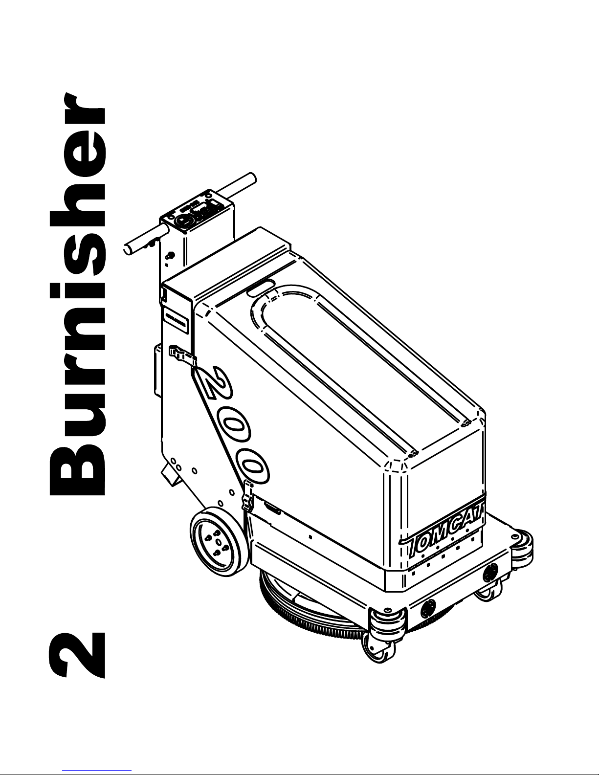
200 Walkie Burnisher
2010 Edition: 1
00
R.P.S. Corporation Phone: 1-800-450-9824
O. Box 241 Fax: 1-866-632-6961
P.
Racine,
Wisconsin 53401

How to use this manual
This manual contains the following sections:
- HOW TO USE THIS MANUAL
- SAFETY
- OPERATIONS
- MAINTENANCE
- PARTS LIST
The HOW TO USE THIS MANUAL section will
tell you how to find important information
for ordering the correct replacement parts.
Parts may be ordered from authorized dealers.
When placing an order for parts, the machine
model and serial number are important.
Refer to MACHINE INFORMATION on page one
of this manual, which is filled out during the
installation of your machine.
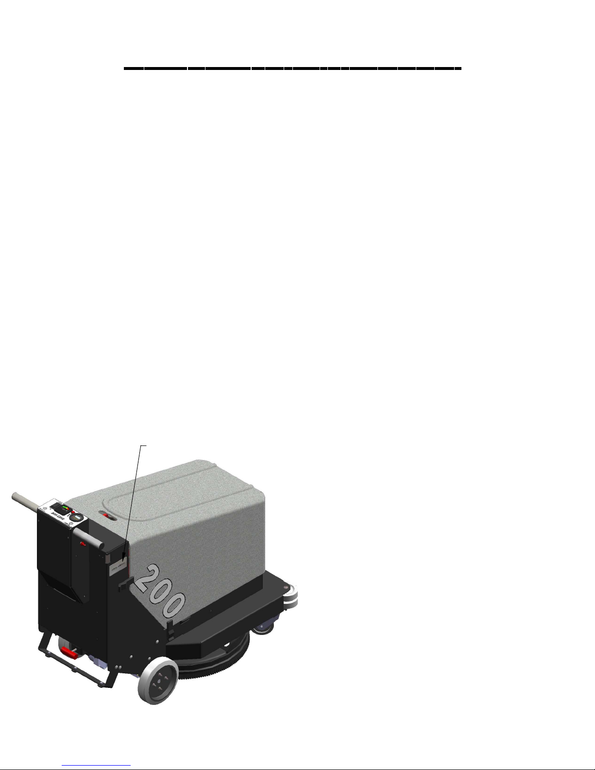
The serial number of your machine is located
on the lower half of steering tower of the
machine. (See Picture Below)
The SAFETY section contains important information
regarding hazard or unsafe practices of the
machine.
Levels of hazards are identified that could result
in product or personal injury, or severe injury
resulting in death.
The OPERATIONS section is to familiarize the
operator with the operation and function of the
machine.
The MAINTENANCE section contains preventative
maintenance information to keep the machine
and its components in good working condition.
They are
listed in this general order:
- Batteries
- Burnishing Pads
- Cleaning Filter
- Service Schedule
- Machine Trouble Shooting
SERIAL NUMBER PLATE
The PARTS LIST section contains assembled parts
illustrations and corresponding parts list. The parts
lists include the following columns of information:
- ITEM - Refers to the reference
number on the parts illustration.
- PART NO. - Lists the part number
for the part.
- QTY - Lists the quantity of the part
used in that area of the machine.
- DESCRIPTION - Is a brief description
of the part.
- COMMENTS -For information not
noted by the other columns.
NOTE: If a service or option kit is installed on your
machine, be sure to keep the KIT INSTRUCTIONS
which came with the kit. It contains replacement
part numbers needed for ordering future parts.

Table of contents
Machine information form
Warranty registration form
Machine specifications
Common wear parts
Safety messages
!!Safety precautions!!
Machine controls and features
Controls and fuctions
Machine preparation
Machine setup
Operation
Pre-burnishing check list
One pass burnishing
Charging batteries
Onboard charger
Maintenance
Preventative maintenance records
Troubleshooting
Machine parts section
Page 1
Page 2
Page 3
Page 4
Page 5
Page 6
Page 7
Page 8
Page 9
Page 10
Page 11
Page 11
Page 11
Page 12
Page 13-14
Page 15
Page 16-17
Page 18-19
Page 20-32
Machine Parts Illustration
Machine Bottom Components
Burnisher Deck
Actuator Slide
Machine Top Components
Central Command
Handle Bar
Pages 21-22
Pages 23-24
Pages 25-26
Pages 27-28
Pages 29-30
Pages 31-32
Machine information
Please fill this area out at the time of installation for future reference.
Model number_____________________________________________________________
Serial number:______________________________________________________________
Installation date:___________________________________________________________
Installing dealer:__________________________________________________________
Dealer contact: ___________________________________________________________
Address:____________________________________________________________________
City, state, zip: _____________________________________________________________
Phone number:_____________________________________________________________
This operator and parts manual should be considered a permanent part of the unit and should remain with the unit at
all times. This operator and parts manual covers all the Tomcat 200 Series burnishers. You may find descriptions and
features that are not on your particular model. The information and specification included in this publication were in
effect at the time of printing. R.P.S. Corporation reserves the right to make changes without notice incurring any
obligation.
To register for warranty, fax your warranty registration form today!
PAGE 1

Common wear parts
Pad
Image ultra high
speed - beige
Luster lite - blue
Combo ultra
high speed
Pad
Function
Ultra high speed
High speed buffing
And burnishing.
Ultra high speed
buffing and
burnishing.
Ultra high speed
buffing and
burnishing.
Results
For high speed buffing
and burnishing. For
frequent burnishing on
soft to medium
finishes.
For burnishing soft
floor finishes. May be
used on a daily basis.
Ideally suited for top
dressing highly
polished floors.
Blended polyester and
natural fibers. For
frequent burnishing on
medium finishes.
200 Part
Number
20-4221
20-4222
20-4223
Porko ultra high
speed
Porko elite
Porko plus
Ultra high speed
buffing and
burnishing.
Ultra high speed
buffing and
burnishing.
Ultra high speed
buffing and
burnishing.
Blended natural fiber
pad. For frequent
minimal burnishing on
hard finishes.
Blended natural fiber
pad works on all UHS
machines. For minimal
burnishing on medium
to hard finishes.
High content of
natural fibers. Ideal
for minimal burnishing
on hard finishes.
20-4224
20-4225
20-4226
PAGE 4

afety Messages
S
Your safety, and the safety of others, is very important and operating this unit safely is an important responsibility.
To help you make informed decisions about safety, we have provided operating procedures and other safety
information in this manual. This information informs you of potential hazards that could hurt you or others.
It is not practical or possible to warn you of all the hazards associated with operating this unit.
You must use your own good judgment.
This is intended for commercial use. It is designed to be used on hard floors in an indoor environment,
with the recommended pads.
1. DO NOT OPERATE UNIT:
Unless trained and authorized.
Unless operator manual is read and understood.
If unit is not in proper operating condition.
2. W
HEN OPERATING UNIT:
Remove loose objects from the floor that may be projected from the revolving burnisher pad.
Keep hands and feet away from revolving pads.
Do not operate machine where flammable liquids or gasses are present.
Use extreme caution when maneuvering.
3. BEFORE LEAVING:
Make sure machine is turned off.
Stop on level surfaces.
4. BEFORE SERVICING:
Stop on level surface, and secure machine.
Disconnect batteries.
PAGE 5

!! Safety Precaution!!
WARNING: Hazardous voltage. Shock, burns or
electrocution can result. Always disconnect the
batteries before servicing machine.
WARNING: Batteries emit hydrogen gases. Explosion or
fire can result. Keep sparks and open flames away.
WARNING: Charge unit in a well ventilated area, and
keep battery compartment open when charging.
Explosion or fire could result.
WARNING: Battery acid can cause burns. Wear
protective eye wear and gloves when servicing
batteries.
WARNING: Do not store outdoors or pressure wash.
Prevent electronic components from getting wet.
WARNING: The use of parts and solutions other than
that recommended by the manufacturer may cause
damage or endanger people.
WARNING: Dress safely. Do not wear rings or metal wrist
watches while working on this machine. They can
cause an electrical short, which, can cause serious
burns. Do not work on this machine while wearing a
tie, scarf or other loose, dangling neckware or clothing.
These loose items can tangle in the rotating parts and
cause serious injury or even death.
WARNING: Always use the charger provided by
the maufacurer to charge the machine.
It is an automatic charger, specifically designed
to charge at the appropriate rate. If you must
use a different charger, disconnect the batteries
before charging. This will prevent damage to the
electronic speed controller.
WARNING: Do not park the machine on ramps
or slopes.
WARNING: Do not operate the machine if
any parts have been removed or damaged.
WARNING: Do not remove, paint over, or
destroy warning decals. If warning decals
become damaged, they must be replaced.
WARNING: Do not operate machine in unsafe
condition. If the machine is in need of repair or
is in any way unsafe to operate, the matter
should be reported immediately to the shift
supervisor. Do not operate the machine until it
is returned to proper operating condition.
WARNING: This machine must only be
operated by trained operator. As part of his
or her training, they must read this manual
thoroughly. If extra copies are needed,
contact your local dealer.
WARNING: Do not use the machine as a step ladder or
chair.
WARNING: Only operate this machine from the
operators position. It was not designed to carry
passengers.
WARNING: Do not operate this machine on ramps or
uneven surfaces. When climbing a ramp, always drive
the machine in forward straight up or down the ramp.
Never drive across the incline. Do not back down or
turn on ramps!
WARNING: Always turn off the machine,
before leaving it unattended.
WARNING: Do not operate over electrical
floor outlets. May result in serious injury.
PAGE 6

Machine Controls and Features
4
2
5
7
6
9
8
3
14
21
22
20
15
16
17
18
19
30
24
2
10
25 26
11
12
27
28
13
29
1
30
23
PAGE 7

ontrols and Fuctions
C
See figures (1-6) on page 7
1. Corner roller bumpers: helps prevent damage to machine when cleaning close to walls and other objects.
2. Rear tires: Non-marking and extra wide tires for stability.
3. Rear transaxle: Provides propulsion for machine.
4. Spring adjustment knob: Increases or decreases the pad pressure.
5. Actuator: The actuator lifts and lowers the deck.
6. Central command box: Holds all electrical switches and control components
7. Handle bar: Used to steer the machine.
8. Batteries: The machine comes standard with (3) 12 volt batteries (Standard) or (Optional) (6) 6 volt batteries
9. Battery access lid: Provides access to batteries for charging and maintenance.
10. Shroud: The shroud contains dust created from burnishing.
11. Shroud curtain: The shroud curtain contains dust created from burnishing.
12. Casters: Twin casters for stability.
13. Clean air intake: The clean air intake allows clean air to flow into
14. Clean air intake hoses: The clean air intake hoses direct clean air into the burnishing motor.
15. Burnisher motor cover: Prevents dust from entering the burnisher motor prolonging motor life.
16. Burnisher motor: This motor drives the burnishing pad driver.
17. Burnisher pad: Burnishes floor
18. Pad retainer clip: Holds burnisher pad to pad driver.
19. Tip back bar: The machine tips back to allow easy access to burnisher pad installment and removal
20. Speed control knob: Controls the drive speed of the machine, turn cloc
couter clockwise to decrease speed.
21. (+) 15 amp resetable circuit breaker: (15 amp) positive bus bar.
22. Key switch: Turns power to machine on and off.
23. Resetable 65 amp burnisher motor circuit breaker: Prevents motor damage do to too much down pressure
the burnishing motor.
.
kwise to increase speed and
24. Burnisher deck switch: Lowers burnisher deck.
25. Burnishing deck pressure gauge: Settings green (safe operating range) - red (overload).
26. Burnishing motor brush indicator: Indicates when the burnisher motor needs new brushe
27. Hour meter: Keeps track of how many hours are on the machine.
28. Battery gauge: Indicates relative battery charge remaining.
29. Reverse switch: Controls the direction of the traction motor.
30. Green control button: Depress to drive the machine forward and release to stop
s.
PAGE 8

M
achine Preperation
Uncrating machine
Carefully check the crate for any sign of Damage. Batteries are in the unit. To uncrate the machine, remove banding from
around the crate. Take off the top and sides And dispose of properly. Remove banding from machine. Remove the
chocks around the drive wheels. Fold down ramp, and roll machine off of the base. Notify the carrier immediately if
concealed damage is discovered.
Connecting batteries
Your machine is equipped with (3) 12 volt, Deep cycle 175, amp hour batteries or, an optional (six) 6 volt, Deep cycle,
245 amp hours batteries, which Form a 36 volt system.
1. Turn all switches to the off position and remove key.
2. Hinge open the battery access lid to access the battery compartment.
3. All of the battery cables are connected to the batteries. Locate any loose ones and connect to the open terminal.
Tighten with 9/16" wrench. (see below)
4. Turn on main power switch and check the battery condition meter to ensure correct installation. Charge batteries if
needed. (see: battery charging)
Standard (3) 12-volt 175 ah
Optional (6) 6-volt 245 ah
PAGE 9

MACHINE SETUP
ATTACHING PAD
1. Turn machine power off.
2. Tip machine back until the tip back bar is
resting safely on floor.
3. Remove blue pad retainer clip from pad
holder.
4. Place pad on top of locking clip and slide
both below burnishing deck directly into the
center of the burnishing disk. (see right)
5. With pad and clip directly in the center of the
burnishing disk push up and screw in the pad clip.
(Hand tighten only) (see right)
TIP BACK BAR
FLOOR
BLUE PAD
RETAINER CLIP
PAD
6. Once the pad is in place, tip the machine
back down to the normal operating position.
7. Run machine and check for vibraitons. If
deck vibrates badly the pad may not be
centered on disk correctly. Remove pad and
reistall pad in the center of disk.
BLUE PAD
RETAINER CLIP
***FOR CORRECT PAD APPLICATION , CALL YOUR LOCAL DEALER***
PAD
SHROUD AND SHROIUD CURTAIN
PAGE 10

Operation
Read and understand the safety section on page
5 and 6 before operating machine.
Operating hints
Pre- burnishing
Check list
1. Check battery condition gauge on the hour
meter/battery gauge. (See below) Make sure
batteries are fully charged before using.
BATTERY GAUGE
2. Check condition of pad and make sure it is
securely in place.
3. Check hose connections from the motor to
the frame are secure. (See below)
One Pass
Burnishing
Steps: (see below)
1. Turn machine on with the key switch.
HOUR METER
2. Lower burnishing head to the floor by simply
depressing the black burnisher deck button.
3. Begin burnishing by holding the green
control button onthe the handle bar.
4. Adjust the red speed control knob to desired
speed located on the side of the central
command box.
5. Once the pad begins to move, check the
pressure gauge. Start burnishing with in the
green marks, do not use yellow marks without
management approval.
6. To operate machine in reverse, simply pull
back on red togel switch located on the right
hand side of central command box.
5. Check condition of shroud curtain the
shroud curtain needs to be in good condition for
dust control system to work properly. (See below)
7. To stop the machine, let go of the green
control button and the machine will stop
automatically.
1 2 354 6
PAGE 11

Battery charging
CAUTION: The following instructions are intended for the 36v charger
supplied with the machine. Do not use any other charger with this machine.
Charger speccifications
Output voltage of 36 volts.
Output current of 25 amps max.
Input voltage of 110 volts/60 Hz.
Automatic shut off circuit.
Made for deep cycle batteries.
Danger: always charge batteries in a well ventilated area.
Batteries emit hydrogen gas. Explosion or fire can result. Keep
sparks and flame away. Shield eyes when servicing batteries
and avoid contact with battery acid. Leave rear hood open
when charging!
1. Transport machine to a well ventilated area for charging.
2. Turn the machine off.
3. Hinge opens the battery access hood to expose the
batteries. (Caution: always wear eye protection when batteries
are exposed)
4. Check the water level in each battery. Do not charge the
machine unless the water is slightly higher than the plates. If
needed, add enough distilled water to just slightly cover the
plates. Do not over fill. Batteries can overflow during charging.
Replace caps before charging.
5. With the grey charger plug disconnected from the machine,
plug the charger power cord into a grounded 110 volt standard
wall outlet.
6. Connect the grey charger plug into the battery charging
port located on the lower portion of the steering tower.
7. The charger will automatically begin charging, and
automatically shut off when fully charged (check gauge)
8. After the charger has turned off, unplug the grey charger
plug from the machine and disconnect the charger from the
wall outlet.
Gray charger
plug
9. Recheck the cell level after charging. If needed, add
distilled water up to the correct level. Be certain to replace the
caps securely and to wipe off the top of the batteries with a
clean cloth.
PAGE 12

Onboard battery charger display
3
1
4
2
5
PAGE 13

Onboard battery charger display
"
bat
" is displayed.
General information and warnings
Electronic automatic battery charger with microprocessor suitable for any battery type.
Fully automatic charging cycle with electronic setting protected against overload, short-circuit at clamps and reversed
polarity.
Never disconnect the battery while charging: this could cause sparks.
Never use the equipment in the rain, in areas used for washing or damp areas.
Before starting to charge, make sure the voltage of the equipment suits the voltage of the battery, that the charging current
suits the capacity of the battery and the selected charging curve(for lead-acid batteries or airtight gel batteries) is correct for
the type of battery to be charged. In addition, make sure the rated input voltage of the charger suits the available supply
voltage and the system is quipped with grounding.
If necessary, replace the fuse with another of the same type and value as indicated on the rating plate.
Use battery chargers only in well ventilated areas.
Pay attention to any remarks on the battery manufacturer.
For lead-acid batteries with liquid electrolyte:
Control the water level after each charging process.
Refill with distilled water only.
Caution! The gasses generated during charging are explosive. Do not smoke in the vicinity of the batteries. When working with
cables and electrical equipment, avoid open flames and sparks.
Attention: Use protective glasses and gloves during battery maintenance. Battery acid causes injuries. In case of contact with
battery acid, wash the affected parts with a lot of fresh water and consult a doctor if necessary.
Controls
1.Three-digit display + symbol (1), to view A = the charging current, U = the battery voltage, h = the charging time, C = the
charging ampere-hours [Ah], e = the energy used [KWh].
2.Button for the selection of the display mode (2): A, U, h, C, E. After about 10 seconds the display returns to the visualization of
the charging current.
3.Red control indicator (3): when it is on, the charging cycle has started.
4.Yellow control indicator (4): when it is on, the final phase of the charging cycle as started.
5.Green control indicator (5): when it is on, the charging cycle has finished.
Operation
Plug the cord into a socket.
Connect the battery, checking the polarity.
Now, the battery chargers display will show a sequence of details on the chargers internal programming: after the name “SPE”,
it will show the software release installed in the equipment, then in sequence, the following parameters: battery voltage,
charging current, charging curve number and, finally, the words “GEL” or “ACD” depending on the set up charging curve
being suitable for airtight gel batteries or lead acid batteries. Make sure the type of batteries to be charged (gel or lead-acid
batteries) matches the displayed details (“GEL” or “ACD”, respectively). If it doesn't, contact our dealer. Now a test is run on the
battery voltage to decide if the charging process should be started or not. If the battery is not connected to the battery
charger, the display will show the word “BAT”. The word will stay on, even if the test is failed (for instance, reversed polarities or
incorrect battery connection). If the test is passed, the display will show the battery voltage for approximately 5 seconds and
the battery will begin to be charged. The charging cycle progress will be shown by red (3), yellow (4) and green (5) LED
indicators. At the end of the charge, when the green indicator (5) is on, unplug the cord from the socket and operate the
machine.
Problems Solutions and checks
The battery charger does not sw itch on. Check that the pug is connected to the supply mains and
that the fuse is effcient
The charging cycle does not start and the message
The yellow indicator (4) will not light up even 15 hours
from the starting of the charging cycle, and the display
The message
If the battery charger is provided w ith a safety
thermostat and the message
The message
The message
The message
is displayed This means that the maximum v oltage admissible by the
E01
is displayed.
E02
is displayed This means that the maximum t im e for the charging
E03
is displayed This means that the total safety tim er has interrupted the
SCt
is displayed This signals a possible internal chart circuit.
Srt
Check the connection to the battery and the polarity.
Check the battery for possible faulty components.
battery has been exceeded. The charging is interupted.
This means that the maximum t emperature has been
exceeded. The charging is interrupted.
phase has been exceeded. The charging is interrupted.
PAGE 14

Maintenance
Daily Maintenance
1. Check pad condition. (Replace if necessary)
2. Check battery charge.
3. Clean dust control filters.
4. Check hoses and verify there are no clogs.
5. Check pads for wear and replace if needed.
6. Charge unit and verify that charger is operating
properly
Monthly
Maintenance
1. Check flex driver
2. Check to see if battery cables are
tightened and clean. (Tighten if needed)
3. Check condition of burnishing deck actuator.
Weekly Maintenance
1. Check battery water level.
2. Check condition of all three tires.
3. Check condition of dust curtains on shroud.
4. Check condition of dust control hoses.
5. Check to see if vacuum exhaust is clear.
Yearly
Maintenance
1. Call your local dealer for yearly maintenance
PAGE 15

Preventative maintenance records
MACHINE INFORMATION
CUSTOMER INFORMATION
CUSTOMER
ADDRESS
CITY STATE ZIP CODE
MODEL # SERIAL #
WORK ORDER# HOUR METER:
BATTERY CONDITION Cell #1 Cell #2 Cell #3
Battery # 1 Hydrometer Reading
Battery # 1 Water Condition
Battery # 2 Hydrometer Reading
Battery # 2 Water condition
Battery # 3 Hydrometer Reading
Battery # 3 Water Condition
Battery # 4 Hydrometer Reading
Battery # 4 Water condition
Battery # 5 Hydrometer Reading
Battery # 5 Water Condition
Battery # 6 Hydrometer Reading
Battery # 6 Water Condition
Clean Battery Tops. Check Battery Cable and Terminal Condition
NOTES:
PAD CONDITION
Pad Good Worn Needs Replacement
Pad retainer Good Worn Needs Replacement
Pad Holder Condition Good Worn Needs Replacement
CHECK OPERATION AND CONDITION OF: IN SPEC REPAIR PROBLEM
Key Switch
Pad Pressure Adjustment
Handlebar Switch
Reverse Switch
Burnish Switch
Burnishing Deck Lift System
Battery Charger Connectors
Battery Charger
PAGE 16

Preventative maintenance records
CLEAN AND/OR LUBRICATE IN SPEC REPAIR PROBLEM
Burnishing Deck Linkage
VISUALLY INSPECT: IN SPEC REPAIR PROBLEM
Vacuum Motor Brushes
Vacuum Hoses
Brush skirts
Pad Motor Brushes
Pad Driver Condition
Drive Wheel Condition
Front Caster Condition
All Rollers
COMMENTS
Technician's Name
Technician's Signature Date
Customer's Name:
Customer's Signature Date
©2006 R.P.S. Corporation
PAGE 17

Trouble Shooting
Problem
No power, nothing operates.
Burnishing motor does not operate.
Drive motor does not operate.
Cause
Faulty key switch.
Batteries need charging.
Faulty battery.
Loose battery cable.
Main circuit breaker tripped.
Burnishing deck is not down.
Burnishing circuit breaker tripped.
Carbon brushes worn.
Faulty motor or wires.
Recharge switch misadjusted.
Faulty speed controller or wires.
Faulty drive motor.
Faulty wiring.
Carbon brushes worn.
Solution
Contact local servicing dealer.
See charging batteries.
Replace battery.
Tighten loose cable.
Wait 5 minutes for auto reset.
determine cause and correct.
Put deck down.
Wait 5 minutes for auto reset
Determine cause and correct.
Contact local servicing dealer.
Contact local servicing dealer.
Contact local servicing dealer.
Contact local servicing dealer.
Contact local servicing dealer.
Contact local servicing dealer.
Contact local servicing dealer.
Drive motor runs incorrectly.
Faulty speed controller or wires.
Faulty potentiometer.
Loose wires.
PAGE 18
Contact local servicing dealer.
Contact local servicing dealer.
Contact local servicing dealer.

Trouble Shooting
Problem
Poor dust control.
Poor burnishing quality.
Burnishing scrub deck noisy.
Cause
Main vacuum hose disconnected.
Burnishing deck hose disconnected.
Burnishing deck hose clogged.
Damaged main vacuum hose.
Damaged burnishing deck hose.
Filter clogged.
Filter door not closed tightly.
Filter door gasket faulty.
Filter full.
Torn shroud curtain.
Faulty vacuum Motor.
Battery charge is low.
Burnishing pads worn out.
Debris stuck to burnishing pad.
Torn burnishing pad.
Faulty disk pad motor.
Battery charge is low.
Missing burnishing pad.
Burnishing pad worn out.
Torn curtain hitting burnishing disks.
Damaged shroud.
Solution
Reconnect hose.
Reconnect hose.
Remove debris.
Contact local servicing dealer.
Contact local servicing dealer.
Clean out filters.
Adjust screw on door clamp to
tighten seal.
Contact local servicing dealer.
Remove debris.
Contact local servicing dealer.
Contact local servicing dealer.
Charge batteries overnight.
Replace pads.
Remove debris.
Replace pads.
Contact local servicing dealer.
Charge batteries overnight.
Replace pads.
Replace pads.
Contact local servicing dealer.
Fix or replace shroud.
Rear tires noisy.
Poor traction.
Short run time.
Bearings dry.
Faulty hubs.
Excessive burnishing pad.
Pressure.
Worn drive tire.
Batteries run down.
Batteries still down.
Batteries low on water.
Batteries over cycled.
PAGE 19
Grease bearings.
Contact local servicing dealer.
Reduce pressure with switch.
Contact local servicing dealer.
Charge batteries twice
Contact local servicing dealer.
Fill with distilled water to 3/4" above
the lead plates.
Contact local servicing dealer.

 Loading...