

Tomberlin 2010 E-Merge Maintenance Manual

TOMBERLIN®CONSUMERDISCLAIMER
Tomberlin®reservestherighttochangethesuggestionsgainedinthisconsumersupportsite.Itis
intendedprimarilyforeducationalpurposesonly.Someexperiencedconsumersprefertodothe
maintenanceandservicethemselves,forthe"DoItYourself"owners,Tomberlinstronglyencourages
interactionwithyourlocaldealerfirstandtoneverattemptaprocedureyouareunfamiliarwithsafely
performing.Anelectricvehiclehasasignificantvoltagethatcanresultinshock,fireandinjuryifnot
performedbyaprofessional.Damagetothevehiclecanalsooccur.Someproceduresrequirespecific
torquesettingsthatwhennotfollowedcanresultindangerous,possiblylifethreateningsituations.
Manyerrorswillnotsurfaceimmediately.Theinformationhereinhasgenerallyproventoenhancethe
lifecycle,safetyandoverallownershipexperiencewhenproperlyfollowed.Tomberlinassumesno
liabilityforthecontentprovidedinthisconsumereducationalsectionanditispossiblethatanerror
withregardtospelling,grammar,nomenclature,andtranslationispresent.Notethattheinformation
providedshouldbetreatedaslivedocumentsmeaningtheyarealwaysinastateofrefinement,
correctionandimprovement.Checkbackoftenandifprinted,checkbackpriortoreliancetoassurethey
remaincurrent.Neverattempttomanipulatethevehicletoexceedthespeedasrequiredby
regulations.ThehighestspeedrangeforTomberlin®E‐Merge™PTV'sandLSV'sarefactorysetat15‐19
mphasaPTVor22‐25mphasanLSV.Consumersshouldalwaysexerciseprudentcommonsense
measures,usepropersafetygearwithtoolsdesignedspecificallyforthetask.Alwaysutilizeinsulated
toolsaroundelectricalconnections.Neverexceedyourcomfortlevelandwhenindoubt,stopandcall
yourlocaldealer.TomberlinAuthorizedDealersarealwaysyourbestresource.Ifyounoticeanerroror
haveanideathatwillimproveoureffortshere,pleaseemailyourideatoinfo@tomberlin.net.

2
INTRODUCTION
This Maintenance Manual is compiled by TOMBERLIN Company for dealers authorized by
the Company and their technicians. The Manual is only for the maintenance and repair of
electric vehicles of E-MERGE series.
TOMBERLIN reserves the rights to revise the specifications and design from time to time
and the electric vehicles and other products. are subject to improvement that may influence
the maintenance procedure with no notice, nor obligation to alternate devices sold
previously.
Before starting any service on the electric vehicle, read the Manual carefully and note the
difference of the following symbols:
This indicates Note! Alarm! Watch your safety!
WARNING The symbol indicates a danger may occur, calling the attentions of
the driver, passenger, by stander or inspection and maintenance
personnel.
CAUTION It describes some special precautions to avoid vehicle damage.

3
Chapter 1 Overview
Safety Precautions................................................................................................................................1-1
Preparation for Emergency ............................................................................................................1-1
Safe Use of Lubricating Oil.............................................................................................................1-1
Safe Use of Battery........................................................................................................................1-1
Protection of Vehicle Safety...........................................................................................................1-2
Electrical Safety During Maintenance.............................................................................................1-2
Use the Designated Lifting Jack.....................................................................................................1-5
Use Appropriate Tools...........................................................................................................................1-6
Special Tools..................................................................................................................................1-6
Instrumentation for Electric Control System...................................................................................1-6
Cautions................................................................................................................................................1-6
Washing and Cleaning...................................................................................................................1-6
Keep Tidy.......................................................................................................................................1-6
Tightening Torque...........................................................................................................................1-7
Parts Replacement .........................................................................................................................1-7
Washer, Grease Fitting and O-ring.................................................................................................1-7
Bearing and Oil Seal ......................................................................................................................1-7
Recommendations on Disassembly and Assembly........................................................................1-7
Chapter 2 Regular Inspection and Adjustment
Regular Maintenance ............................................................................................................................2-1
Periodic Lubrication Plan.......................................................................................................................2-2
Braking System..................................................................................................................................2-4
Braking Inspection.............................................................................................................................2-4
Inspection of Parking Brake...............................................................................................................2-5
Inspection of Brake Drum and Brake Shoe ........................................................................................2-6
Inspection of the Accelerator Pedal ...................................................................................................2-9
Inspection of the Steering System.....................................................................................................2-9
Inspection of the Steering Linkage...................................................................................................2-10
Inspection of Stub Axle....................................................................................................................2-11
Inspection of the Front Wheel Alignment.........................................................................................2-11
Install for the Adjustment of Toe-in:.................................................................................................2-12
Inspection of Tires and Wheel Rim..................................................................................................2-12
Inspection of the Front Wheel Bearing.............................................................................................2-13
Inspection of the Rear Axle Bearing ................................................................................................2-13
Inspection of the Shock Damper......................................................................................................2-14
Inspection of the Seat Belt...............................................................................................................2-14
Chapter 3 Canopy
Removal of the Canopy.........................................................................................................................3-1
Remove..........................................................................................................................................3-1
Install..............................................................................................................................................3-1

4
Removal of Canopy Rods......................................................................................................................3-1
Remove..........................................................................................................................................3-1
Install..............................................................................................................................................3-2
Removal of the Pillar.............................................................................................................................3-2
Remove..........................................................................................................................................3-2
Install..............................................................................................................................................3-3
Chapter 4 Body
Removal of the Front Bumper ...............................................................................................................4-1
Remove..........................................................................................................................................4-1
Removal of the Rear Tray................................................................................................................4-1
Remove..........................................................................................................................................4-1
Removal of the Rear Bumper.........................................................................................................4-1
Remove..........................................................................................................................................4-1
Install..............................................................................................................................................4-1
Removal of the Seat Cushion................................................................................................................4-2
Remove..........................................................................................................................................4-2
Install..............................................................................................................................................4-3
Removal of Front Cover ........................................................................................................................4-4
Remove..........................................................................................................................................4-4
Install..............................................................................................................................................4-4
Removal of the Dashboard....................................................................................................................4-4
Remove..........................................................................................................................................4-4
Install..............................................................................................................................................4-5
Removal of the Rear Cover...................................................................................................................4-6
Remove..........................................................................................................................................4-6
Install..............................................................................................................................................4-6
Rear cover.............................................................................................................................................4-9
Chapter 5 Front Axle
Front axle ..............................................................................................................................................5-1
Removal of the Front Axle.....................................................................................................................5-2
Remove .............................................................................................................................................5-2
Inspect...............................................................................................................................................5-6
Install .................................................................................................................................................5-7
Chapter 6 Driving Axle
Driving axle............................................................................................................................................6-1
Removal of the Driving Axle..................................................................................................................6-2
Remove..........................................................................................................................................6-2
Inspect and test..............................................................................................................................6-5
Install..............................................................................................................................................6-6
Gearbox.................................................................................................................................................6-8
Removal of the Differential Gear...........................................................................................................6-9
Remove..........................................................................................................................................6-9

5
Inspection.....................................................................................................................................6-11
Install............................................................................................................................................6-12
Chapter 7 Brake System
Brake System........................................................................................................................................7-1
Brake Pedal...........................................................................................................................................7-2
Parking brake handle ............................................................................................................................7-3
Accelerator pedal ..................................................................................................................................7-4
Chapter 8 Steering System
Steering System....................................................................................................................................8-1
Removal of the Steering System....................................................................................................8-2
Removal of the Steering Gear........................................................................................................8-3
Disassembly of the Steering Gear..................................................................................................8-4
Install..............................................................................................................................................8-7
Chapter 9 Electric Component
Key switch removal........................................................................................................................9-1
Key switch installation....................................................................................................................9-1
Removal of forward/reverse gear switch........................................................................................9-1
Installation of forward/reverse gear switch.....................................................................................9-2
Battery discharge meter removal ...................................................................................................9-2
Battery discharge meter installation...............................................................................................9-3
Horn removal..................................................................................................................................9-3
Horn installation .............................................................................................................................9-3
Combination switch removal ..........................................................................................................9-4
Combination switch installation......................................................................................................9-4
Controller removal..........................................................................................................................9-5
Controller installation......................................................................................................................9-6
Charger receptacle removal...........................................................................................................9-7
Charger receptacle installation.......................................................................................................9-7
Battery removal..............................................................................................................................9-7
Battery installation..........................................................................................................................9-8
DC converter removal ....................................................................................................................9-8
DC converter installation................................................................................................................9-8
Removal of DC changeover contactor and diode assembly...........................................................9-9
Installation of DC changeover contactor and diode assembly......................................................9-10
Motor removal..............................................................................................................................9-10
Motor installation..........................................................................................................................9-12
Removal of bulb of headlight and front turn signal light................................................................9-12
Headlight installation....................................................................................................................9-13
Tail light removal..........................................................................................................................9-13

6
Tail light installation......................................................................................................................9-14
High mount stop lamp removal.....................................................................................................9-14
High mount stop lamp disassembly..............................................................................................9-14
High mount stop lamp installation ................................................................................................9-14
Wiper removal..............................................................................................................................9-15
Chapter 10 Troubleshooting
Troubleshooting Instructions Part 1.....................................................................................................10-1
Check procedures........................................................................................................................10-3
Index for check procedures..........................................................................................................10-3
Check Procedure 1-- Battery/ voltage check................................................................................10-4
Check Procedure 2--Accelerator signal voltage...........................................................................10-4
Check Procedure 3-- Motor voltage at A1 and A2........................................................................10-4
Check Procedure 4 - TOW/RUN switch .......................................................................................10-5
Check Procedure 5—Battery voltage...........................................................................................10-5
Check Procedure 6—Circuit check for key switch and accelerator pedal switch..........................10-5
Check Procedure 7--Controller signal
…
…
…
…
…
…
…
…
…
…
…
…
…
…
…
…
…
…
…
…
…
…
…
…
…
…
…
…
…
…
…
…
…
…
…
…
…
…
…
…
…
…
…
…
…
…
…
…
…
…
…
…
…
…
…
…
…
…
…
…
…
…
…
…
…
…
…
…
…
…
…
…
…
…
…
10-7
Check Procedure 7A—Pin 1
…
…
…
…
…
…
…
…
…
…
…
…
…
…
…
…
…
…
…
…
…
…
…
…
…
…
…
…
…
…
…
…
…
…
…
…
…
…
…
…
…
…
…
…
…
…
…
…
…
…
…
…
…
…
…
…
…
…
…
…
…
…
…
…
…
…
…
…
…
…
…
…
…
…
…
…
…
…
…
…
…
…
…
…
10-7
Check Procedure 7B—Pin 4 and 5
…
…
…
…
…
…
…
…
…
…
…
…
…
…
…
…
…
…
…
…
…
…
…
…
…
…
…
…
…
…
…
…
…
…
…
…
…
…
…
…
…
…
…
…
…
…
…
…
…
…
…
…
…
…
…
…
…
…
…
…
…
…
…
…
…
…
…
…
…
…
…
…
…
…
…
10-8
Check Procedure 7C—Pin 7
…
…
…
…
…
…
…
…
…
…
…
…
…
…
…
…
…
…
…
…
…
…
…
…
…
…
…
…
…
…
…
…
…
…
…
…
…
…
…
…
…
…
…
…
…
…
…
…
…
…
…
…
…
…
…
…
…
…
…
…
…
…
…
…
…
…
…
…
…
…
…
…
…
…
…
…
…
…
…
…
…
…
…
…
10-9
Check Procedure 7
D
—Pin 6
…
…
…
…
…
…
…
…
…
…
…
…
…
…
…
…
…
…
…
…
…
…
…
…
…
…
…
…
…
…
…
…
…
…
…
…
…
…
…
…
…
…
…
…
…
…
…
…
…
…
…
…
…
…
…
…
…
…
…
…
…
…
…
…
…
…
…
…
…
…
…
…
…
…
…
…
…
…
…
…
…
…
…
…
10-9
Check Procedure 7E—Pin 3
…
…
…
…
…
…
…
…
…
…
…
…
…
…
…
…
…
…
…
…
…
…
…
…
…
…
…
…
…
…
…
…
…
…
…
…
…
…
…
…
…
…
…
…
…
…
…
…
…
…
…
…
…
…
…
…
…
…
…
…
…
…
…
…
…
…
…
…
…
…
…
…
…
…
…
…
…
…
…
…
…
…
…
…
10-9
Check Procedure 8 – voltage at the red wire jack of charger rec
eptacle....................................
10-10
Check Procedure 9—Motor speed sensor .................................................................................10-10
Check Procedure 10—forward/reverse gear switch................................................................... 10-11
Check Procedure 11—Reverse buzzer...................................................................................... 10-11
Check Procedure 12 -- Battery discharge meter........................................................................10-12
Check Procedure 13-- High mount stop lamp ............................................................................10-12
Check Procedure 14 - wiper.......................................................................................................10-13
Check Procedure 15—flashing light...........................................................................................10-13
Troubleshooting Instructions Part 2............................................................................................10-14
CHAPTER 11 BATTERY AND CHARGER
Battery.................................................................................................................................................11-1
Overview......................................................................................................................................11-1
Common misconceptions about battery.......................................................................................11-2
Battery replacement.....................................................................................................................11-3
Battery maintenance ....................................................................................................................11-4
Preventative maintenance............................................................................................................11-4
Self discharge .............................................................................................................................. 11-5
Electrolyte liquid level................................................................................................................... 11-5
Mineral content............................................................................................................................. 11-6
Vibration damage.........................................................................................................................11-6

7
Battery charging...........................................................................................................................11-6
Deep discharge............................................................................................................................ 11-7
Premature excessive discharge...................................................................................................11-7
AC power supply line....................................................................................................................11-7
Alternating use of vehicles ........................................................................................................... 11-7
Electric vehicle and charger numbering ....................................................................................... 11-8
Battery troubleshooting diagram .................................................................................................. 11-9
Inspection and test of the battery ...............................................................................................11-10
Inspection and test of the battery charger..................................................................................11-10
Charging voltage inspection....................................................................................................... 11-10
Inspection with hydrometer ........................................................................................................11-10
Procedures for inspection with hydrometer................................................................................ 11-11
Calibration of hydrometer........................................................................................................... 11-11
Hydrometer inspection result presentation................................................................................. 11-11
Discharge test............................................................................................................................11-12
Procedures for discharge test .................................................................................................... 11-13
Discharge test result presentation..............................................................................................11-13
Battery troubleshooting example................................................................................................11-14
Battery storage...........................................................................................................................11-15
Battery charge
r …
…
…
…
…
…
…
…
…
…
…
…
…
…
…
…
…
…
…
…
…
…
…
…
…
…
…
…
…
…
…
…
…
…
…
…
…
…
…
…
…
…
…
…
…
…
…
…
…
…
…
…
…
…
…
…
…
…
…
…
…
…
…
…
…
…
…
…
…
…
…
…
…
…
…
…
…
…
…
…
…
…
…
…
…
…
…
…
…
…
…
…
…
…
…
…
…
…
…
…
…
…
…
…
…
…
…
…
11-16
Overview....................................................................................................................................11-16
Conditions to be noted before charging...................................................................................... 11-16
Get to know the charger............................................................................................................. 11-17
Removal of the charger.............................................................................................................. 11-18
Maintenance of the battery charger............................................................................................ 11-19
Troubleshooting ......................................................................................................................... 11-19
Diode test procedure.................................................................................................................. 11-20
Procedures for component replacement .................................................................................... 11-20
Charger trouble-shooting procedure...........................................................................................11-20
On-board charger …
…
…
…
…
…
…
…
…
…
…
…
…
…
…
…
…
…
…
…
…
…
…
…
…
…
…
…
…
…
…
…
…
…
…
…
…
…
…
…
…
…
…
…
…
…
…
…
…
…
…
…
…
…
…
…
…
…
…
…
…
…
…
…
…
…
…
…
…
…
…
…
…
…
…
…
…
…
…
…
…
…
…
…
…
…
…
…
…
…
…
…
…
…
…
…
1
1-23
Operatin
g Instructions…
…
…
…
…
…
…
…
…
…
…
…
…
…
…
…
…
…
…
…
…
…
…
…
…
…
…
…
…
…
…
…
…
…
…
…
…
…
…
…
…
…
…
…
…
…
…
…
…
…
…
…
…
…
…
…
…
…
…
…
…
…
…
…
…
…
…
…
…
…
…
…
…
…
…
…
…
…
…
…
…
…
…
…
…
…
…
…
…
…
…
…
…
1
1-23
Maintenance instructions …
…
…
…
…
…
…
…
…
…
…
…
…
…
…
…
…
…
…
…
…
…
…
…
…
…
…
…
…
…
…
…
…
…
…
…
…
…
…
…
…
…
…
…
…
…
…
…
…
…
…
…
…
…
…
…
…
…
…
…
…
…
…
…
…
…
…
…
…
…
…
…
…
…
…
…
…
…
…
…
…
…
…
…
…
…
…
1
1-24
Specifications…
…
…
…
…
…
…
…
…
…
…
…
…
…
…
…
…
…
…
…
…
…
…
…
…
…
…
…
…
…
…
…
…
…
…
…
…
…
…
…
…
…
…
…
…
…
…
…
…
…
…
…
…
…
…
…
…
…
…
…
…
…
…
…
…
…
…
…
…
…
…
…
…
…
…
…
…
…
…
…
…
…
…
…
…
…
…
…
…
…
…
…
…
…
…
…
…
…
…
…
…
…
…
…
…
1
1-24
Inst
allation Instructions…
…
…
…
…
…
…
…
…
…
…
…
…
…
…
…
…
…
…
…
…
…
…
…
…
…
…
…
…
…
…
…
…
…
…
…
…
…
…
…
…
…
…
…
…
…
…
…
…
…
…
…
…
…
…
…
…
…
…
…
…
…
…
…
…
…
…
…
…
…
…
…
…
…
…
…
…
…
…
…
…
…
…
…
…
…
…
…
…
…
…
…
…
1
1-25
Chapter 12 Electric Motor
Overview .............................................................................................................................................12-1
Exterior inspection of the electric motor ..............................................................................................12-1
Check Procedure 1-internal short circuit...........................................................................................12-1
Check Procedure 2-disconnection of armature circuit.......................................................................12-1
Check Procedure 3-open excitation circuit........................................................................................12-2
Removal of the electric motor..............................................................................................................12-3
Inspection and test of the motor element ............................................................................................12-4
Inspection of the armature............................................................................................................12-4
Armature earth test.......................................................................................................................12-4

8
Inspection of the excitation winding..............................................................................................12-5
Motor element..............................................................................................................................12-5
Bearing inspection........................................................................................................................12-6
Removal of the bearing................................................................................................................12-6
Mounting of the bearing................................................................................................................12-6
Inspection of the speed sensor magnet........................................................................................12-6
Removal of the speed sensor magnet..........................................................................................12-7
Mounting of the speed sensor magnet.........................................................................................12-7
Readjustment of the electric motor...............................................................................................12-7
Specifications for the electric motor.....................................................................................................12-8
Assembly of the electric motor ............................................................................................................12-9
Mounting of the electric motor...........................................................................................................12-11
Speed sensor of the electric motor....................................................................................................12-14
Inspection of the speed sensor of the electric motor..................................................................12-14
Removal of the speed sensor.....................................................................................................12-14
Mounting of the speed sensor of electric motor..........................................................................12-14
Overview
MERGE 1-1
Chapter 1
Safety Precautions
WARNING
During the maintenance of these vehicles, the following safety precautions can be taken to prevent
serious accidents.
Preparation for an Emergency
To prevent a potential in jury or fire hazard, the following
simple articles should be prepared. For example:
• First-aid kit
• Fire extinguisher
• Emergency phone
Safe Use of Lubricating Oil
While refilling or replacing oil, do not smoke and keep
away from fire.
Any spilled grease should cleaned on a regular basis
and be handled properly.
Safe Use of Battery
Before maintenance, the battery acid should be sealed.
The battery can give off explosive gases. The battery
should be kept away from the ignition source. The liquid
level of electrolyte should be inspected with the use of
flashlight.
Do not measure and test the voltage after connecting the
battery wire. A voltmeter or hydrometer should be used
for taking this measurement.
Do not connect the wire with the negative electrode first.
Connect it at last.
Do not charge the battery while it is refrigerated. The
battery should be unfrozen before it is charged.
To prevent the production of explosive hydrogen gas, the

Overview
MERGE 1-2
Chapter 1
battery should be placed in an area with good ventilation
while charging.
The electrolyte of the battery contains sulfuric acid,
which is toxic and highly corrosive and should be
prevented from being spilled onto the skins, eyes and
clothes. In the event that electrolytes are spilled into
eyes, water should be used to clean the eyes for 15
minutes and effective medical treatment should be
taken.
WARNING
During the maintenance of these vehicles, the following
safety precautions can be adopted to prevent serious
accidents.
Vehicle Safety During Maintenance
• The parking brake should be applied.
• Blocks should be placed in front of the front tires.
• No one should be allowed to stand in front of or
behind the vehicle being serviced.
Electrical Safety During Maintenance
DANGER
• Battery contains explosive gas! Smoking is strictly
prohibited. Sparks and open flames should be kept
away from the electric vehicle and the working area.
The place where the battery is charged should be a
space where it is kept in good ventilation. While
maintaining or working beside the battery, the
operator should wear a full face mask and rubber
gloves.
• Batteries are toxic and contain acid fluid that may
cause serious burns if the fluid should contact the
skin. Anti-acid measures:
Overview
MERGE 1-3
Chapter 1
• Exterior: Flush the area where acid is spilled with
water, and visit the doctor immediately.
• Oral medication: Drink a large quantity of milk or
water before taking milk of magnesia or vegetable
oil. Visit the doctor immediately.
• Eyes: If battery acid should contact your eyes, you
should flush your eyes with water for 15 minutes
and immediately contact your doctor.
WARNING
• The electric vehicle can only be repaired or
maintained by technician with adequate training.
Even the personnel who are in charge of simple
repair or maintenance are required to have the
knowledge or experience in relation to electrical and
mechanical maintenance.
• Please follow the procedures contained in this
Manual, and note all the “DANGER”, “WARNING”
AND “NOTICE” marks contained in this Manual and
attached to the electric vehicle.
• Misuse of electric vehicles or inappropriate
maintenance may result in the performance
degradation of the vehicle or serious personal injury.
• Any refit or alteration of the electric vehicle that may
affect its stability or maneuverability or any speed
increase beyond the maximum speed specified in
the manufacturer’s specifications may result in
death and serious personal injury.
• Refer to the user’s manual for the corresponding
positions labeled on the electric vehicle of all
“WARNING” marks and ensure that they are in
place and easily visible.
• During the maintenance of electric vehicle, please
wear the safety goggles or effective eye-shields.
While maintaining or working beside the battery, the
operator should wear full face mask and rubber
gloves. During the maintenance of electric vehicle, it
is strictly prohibited to wear loose clothes or earrings,
watches, necklace and bracelets, etc.
Overview
MERGE 1-4
Chapter 1
• Moveable elements! It is strictly prohibited to
maintain the electric vehicle while it is in operation.
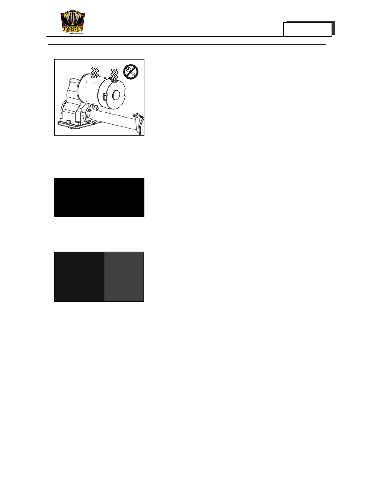
• Hot! It is strictly prohibited to maintain a hot motor.
Any violation of this warning may result in serious
burns.
• While working beside the battery or electrical
element, the operator should use insulated tools
with special care to avoid short circuit of the
component or wiring.
• Before servicing the electric vehicle, please turn the
key switch to the OFF position and take the key out.
Turn FWD/REV switch to NEUTRAL position and
chock the wheels with blocks.

Overview
MERGE 1-5
Chapter 1
• To avoid unintentional start-up of the electric
vehicle, please turn the Tow/Run switch to the
TOW position before disconnecting or
connecting the battery.
• After disconnection of the battery, please wait for 90
seconds to allow for the discharge of the capacitor
in the controller.
NOTICE:
After removing or replacing the wire, please arrange
and fix the wiring and wiring harness. Inappropriate
arrangement of the wiring and wiring harness may
result in the malfunction of the vehicle, property
damage and/or personal injury and death.
Use the Designated Lifting Jack
Front: put the lifting jack below the pivot to support it.
Rear: Use the portion of crossed frames.
Caution:
In the case that the lifting jack is placed behind the
vehicle, the lifting jack should be prevented from
touching the back tower bar.
First, remove the
positive electrode
cable
Disconnect the
storage battery
cable here
Overview
MERGE 1-6
Chapter 1
Use Appropriate Tools
To prevent the components and the vehicle from damage,
appropriate tools must be used.
Special Tools
The use of appropriate special tools is necessary for the
improvement of vehicles, accurate adjustment and
assembly. The use of appropriate special tools can
prevent damage resulting from the use of inappropriate
tools.
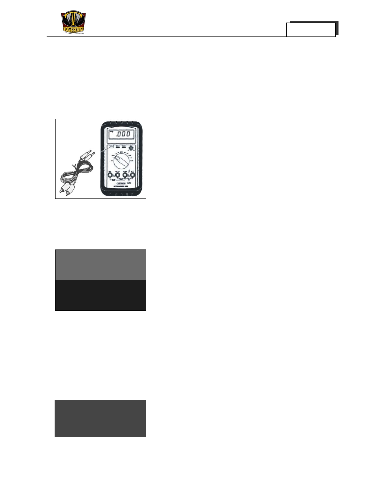
Instrumentation for Electric Control System
1. Pocket detector
This device is of vital importance to the inspection of
the electrical control system.
2. Hydrometer
This instrument is designed to measure the precise
specific grayte. of the electrolyte.
Cautions
Washing and Cleaning
Before the maintenance, thoroughly clean the body and
exterior of the components. During the cleaning, care
should be taken to protect electrical components such as
the relay and controller.
Keep Tidy
To ensure that vital parts are not misplaced, put them in a
secure location away from disarray.

Overview
MERGE 1-7
Chapter 1
Tightening Torque
Tighten the bolts, nuts or screws pursuant to the
instructions on the torque in each chapter.
Parts Replacement
We recommend that you use E-MERGE original parts for
all replaceable parts. Use the oil or grease
recommended by TOMBERLIN during the assembly,
inspection and repair.
Washer, Grease Fitting and O-ring
During the inspection and repair of vehicles, all the
washers, grease fittings and O-rings removed should be
cleaned up before being mounted.
Bearing and Oil Seal
During the mounting of bearing and oil seals on which
the manufacturer’s mark and number are present, the
mark and number should face outwards for easy
identification. All the bearing and oil seals, once removed,
must be replaced with new ones. To apply th e oil seal,
cover a thin layer of light lithium grease over the oil seal.
While mounting the bearing, the lubricants should be
fully applied.
Recommendations on Disassembly and Assembly
Follow the following recommendations to remove and
mount the parts:
• Whenever the parts are disassembled, they must be
cleaned and air dried.
• Apply the lubricant oil over the surface of the parts that
are to be mounted.
• After the mounting of all parts in place, verify that all
movable parts are in normal operation.
Original
Regular Inspection and Adjustment
MERGE 2-1
Chapter 2
Regular Maintenance
Normal maintenance is of paramount importance to the optimal performance and safe operation of
vehicles.
B WARNING
Unless otherwise required, the master switch must be turned off and the parking brake must be
applied during the maintenance.
C–Check CA-Check and Adjustment R-Replacement S-Service CL-Cleaning and Lubricating
L-Lubricating
Remarks
Before
operation
3100 miles
5000
kilometers
(Semiannuall
y)
6200 mile
10000
kilometers
(Annually)
12400 miles
20000
kilometers
(Every two
years)
18600 miles
30000
kilometers
(Every three
years)
Charging
S S S S S
Clean the top of the
battery and inspect the
retaining screws and
terminals for tightness.
S S S S S
Inspect the brake pedal
for free travel and make
adjustments when
necessary.
C CA CA CA CA
Inspect the operation of
the steering wheel
C C C C C
Inspect the tire pressure
and the tire recession
and tread for damage
C CA CA CA CA
Inspect the body and
chassis for damage
C C C C C
Inspect all the bolts, nuts
and screws for tightness
C C C C C
Inspectio
n before
operatio
n
Inspect the reverse
buzzer for normal
operation
C C C C C
Inspect the level of the
electrolyte
C C C C
Monthly
inspectio
n
Inspect all the connecting
lines
C C C C
Regular Inspection and Adjustment
MERGE 2-2
Chapter 2
Clean/Lubricate the pedal
control area
L L L L
Inspect all the insulated
wires for rupture or
dirtiness
C C C C
Semian
nual
inspecti
on
Inspect the shock
damper for oil leakage
and damage of spring
C C C C
Conduct discharging test
S S S
Use terminal protective
agent
S S S
Inspect the brake shoes
for tightness and the rear
axle bearing for normal
operation
C C C
Inspect the steering
knuckle bushing for
normal operation/Adjust
front wheel alignment
CA CA CA
Inspect the nuts of the
wheel for tightness and
the front-wheel bearing
for normal operation
C C C
Replace the lubricating
oil in the gear box
R
Annual
inspecti
on
Inspect the parking pedal
for free travel and make
adjustments when
necessary.
CA CA CA
Inspect the rear axle
bearing and replace it if
abrasion is identified
R
Inspectio
n every
three
years
Inspect for oil leakage,
and adjust the gear box
when necessary
CA
Regular Inspection and Adjustment
MERGE 2-3
Chapter 2
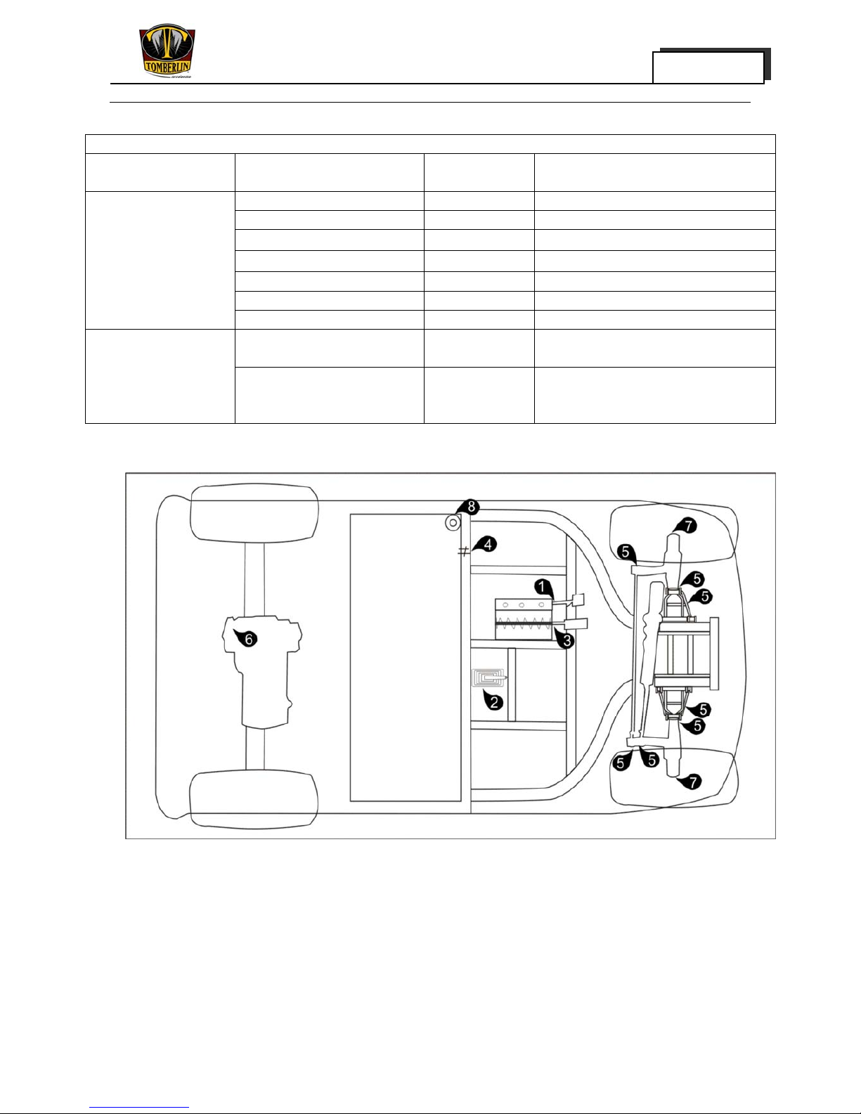
Periodic Lubrication Plan
Periodic lubrication plan
Normal intervals Maintenance
Lubricated
points
Recommend lubricating oil
Brake pedal shaft 1 3# Lithium based grease
Parking brake 2 3# Lithium based grease
Accelerator pivot bar foot 3 3# Lithium based grease
Charger receptacle 4 NYE760G
Front suspension 5 3# Lithium based grease
Front stub axle 7 Lithium based grease
The user or trained
technician applies the
lubricating oil once a
quarter (every 50
working hours)
Braking grease cup 8 DOT3 (3000)brake oil
Inspect the driving axle/oiled
cork position.
6
32.8 ounce(1.1 liter),37OZ
lubricating oil (GL - 5)
The trained
technician applies the
lubricating oil once a
year (every 100
working hours)
Inspect the front-wheel
bearing (Remount when
necessary).
7 3# Lithium based grease

Regular Inspection and Adjustment
MERGE 2-4
Chapter 2
Braking System
Main Brake Inspection
1. Remove:
· Anti-slip pedal
· Protective cover plate
Care should be taken to avoid scraping the body.
2. Inspect:
· Brake master cylinder ①
· Brake Oil Pipeline ②
· Tee joint ③
· Front wheel brake caliper ④
Oil leakage →if any, replacement is required
· Front wheel brake shoe
Standard thickness
7.0 mm (0.28 in)
Maximum wear value of thickness:
2.5 mm (0.1 in)
· Brake disc
Standard thickness:
4.0 mm (0.16 in)
Maximum thickness wear value:
1.0 mm (0.04 in)
Damaged/defective one is to be replaced

Regular Inspection and Adjustment
MERGE 2-5
Chapter 2
3. Measure:
· Free play of the brake pedal
Push against the pedal by hand (slightly) and measure
the distance it travels before the pressure is lost.
Defects are to be replaced.
Free Travel of the brake pedal
13mm(0.512 in)
Inspection of Parking Brake
1. Turn the key switch to "OFF" position and take out the
key.
2. Remove the protecting jacket of brake handle.
1. Inspect:
· Parking brake ratchet①
· Ratchet brake②
Worn or damaged ones are to be replaced.
2. Measure:
· Free travel
15mm (0.591in)
In case of non-compliance with the standard,
adjustment is to be made.
Regular Inspection and Adjustment
MERGE 2-6
Chapter 2
Procedures for the Adjustment of Free Travel
· Loosen the locknut ④
· Adjust the free travel via adjusting nut ③
· Tighten the locknut
· Re-inspect the free travel
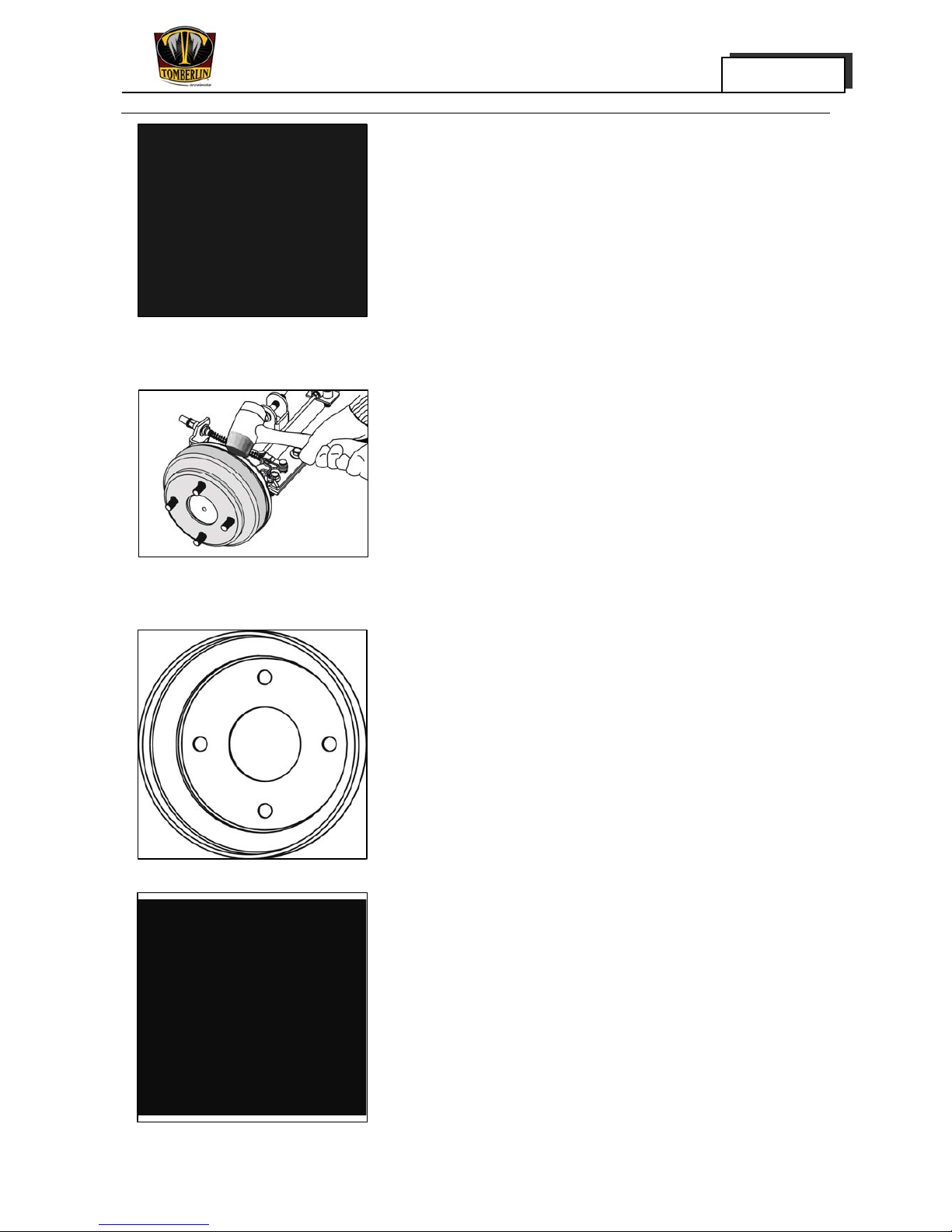
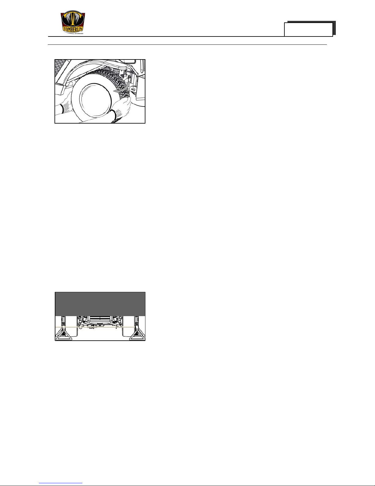
Inspection of Brake Drum and Brake Shoe
1. Turn the key switch to the "OFF" position and take
out the key.
2. Wedge the blocks onto the front lower part of the
front tires. Lift the rear body with the lifting jack.
3. Remove the rear tire lug nuts and then the rear
wheels.
4. Loosen the brake drum and knock slightly on the
drum with mallet.
5. Inspect:
· Internal surface of the brake drum
Oil → fully clean until no oil is found
Scrape → Rub lightly with the abrasive cloth
· Brake wheel cylinder
Where the upstream assembly is in normal working
condition, step on the brake pedal. In case the brake
wheel cylinder cannot open the brake shoe or oil
leakage is found, the brake wheel cylinder is to be
replaced with a new one.
Regular Inspection and Adjustment
MERGE 2-7
Chapter 2
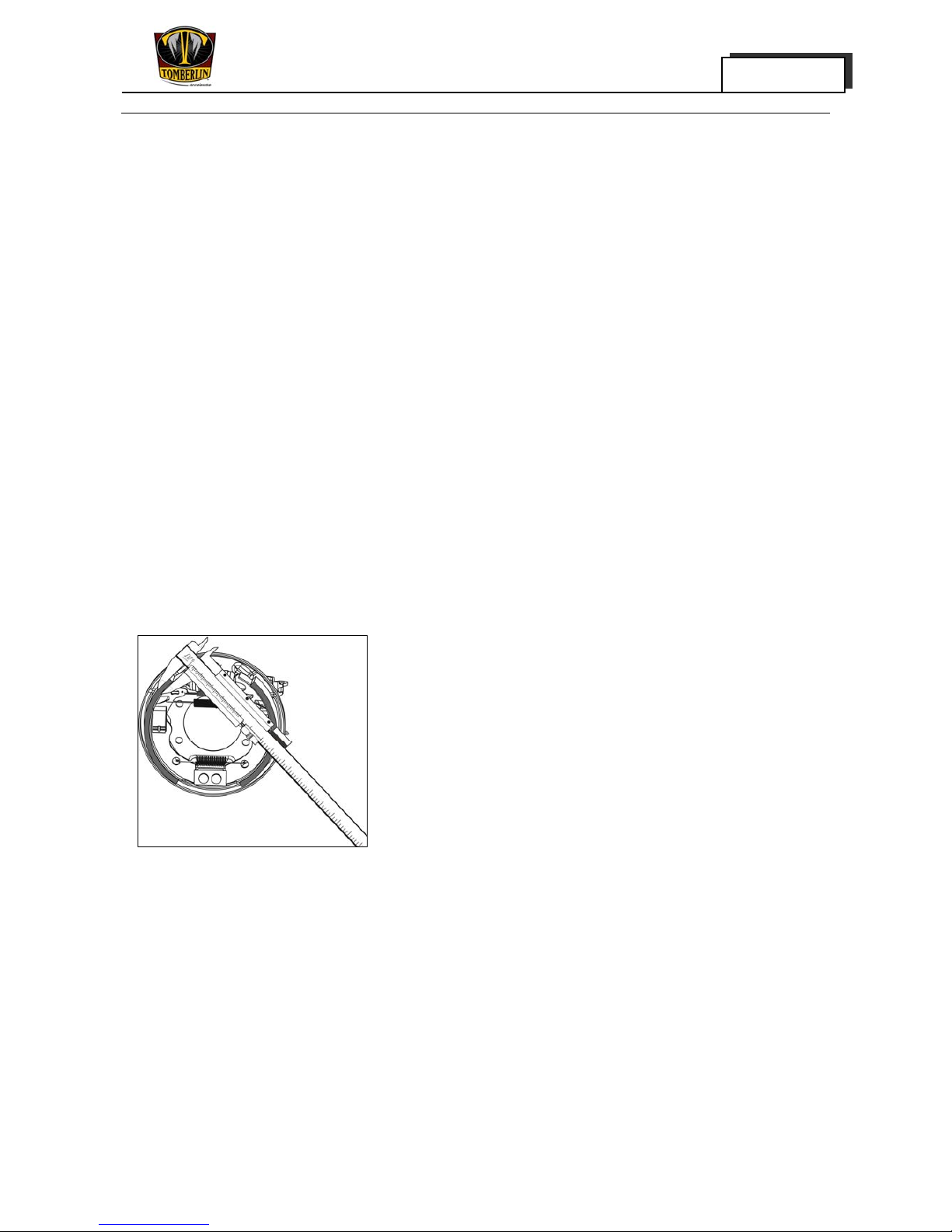
6. Measure
In case the inside diameter of the drum does not
meet the specification, it will be replaced with a new
one.
Standard inside diameter:
180mm(7.2 in)
Maximum wearing value of the inside diameter:
1.5mm(0.06 in)
7. Inspect:
· Surface of shoe block
Oil → Replace the old one or fully clean until no oil is
found
Scrape → Rub lightly with the abrasive cloth
8. Measure the thickness of the shoe plate, and replace
the shoe plate that does not meet the specifications
or in case brake shoe block is too old.
Standard thickness:
7.0 mm (0.16in)
Maximum thickness wearing value:
1.75mm (0.07in)
Regular Inspection and Adjustment
MERGE 2-8
Chapter 2
9. Install
· Brake drum
· Rear wheel
WARNING:
Verify that there is no oil or water on the surface of
the brake drum and shoe block.
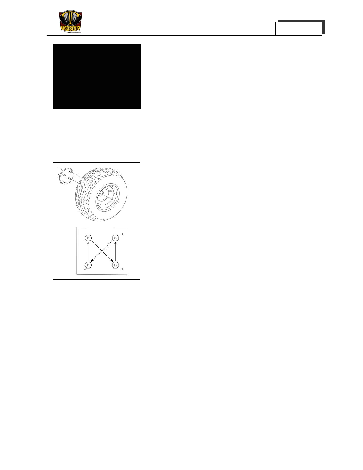
10. Install:
Wheel nuts
Tightening torque to
90N·m (66.4ft·1b)
NOTICE:
First, screw on the wheel nuts by hand, and then
tighten the nuts diagonally.
11. Upon the completion of the installation, step on the
brake pedal about 10 times to adjust the clearance
between the shoe plate and the drum.
Regular Inspection and Adjustment
MERGE 2-9
Chapter 2
Inspection of the Accelerator Pedal
1. Inspect:
Operating condition of the pedal
In case of unsmooth operation, the pivot should be
lubricated.
2. Inspect:
Lateral free travel of the pedal
4mm (0.158 in)
Step on the pedal and replace the pivot in case the
free play is too loose.
Limit value to the free pedal travel:
95mm (3.74in), measured at the top of the pedal
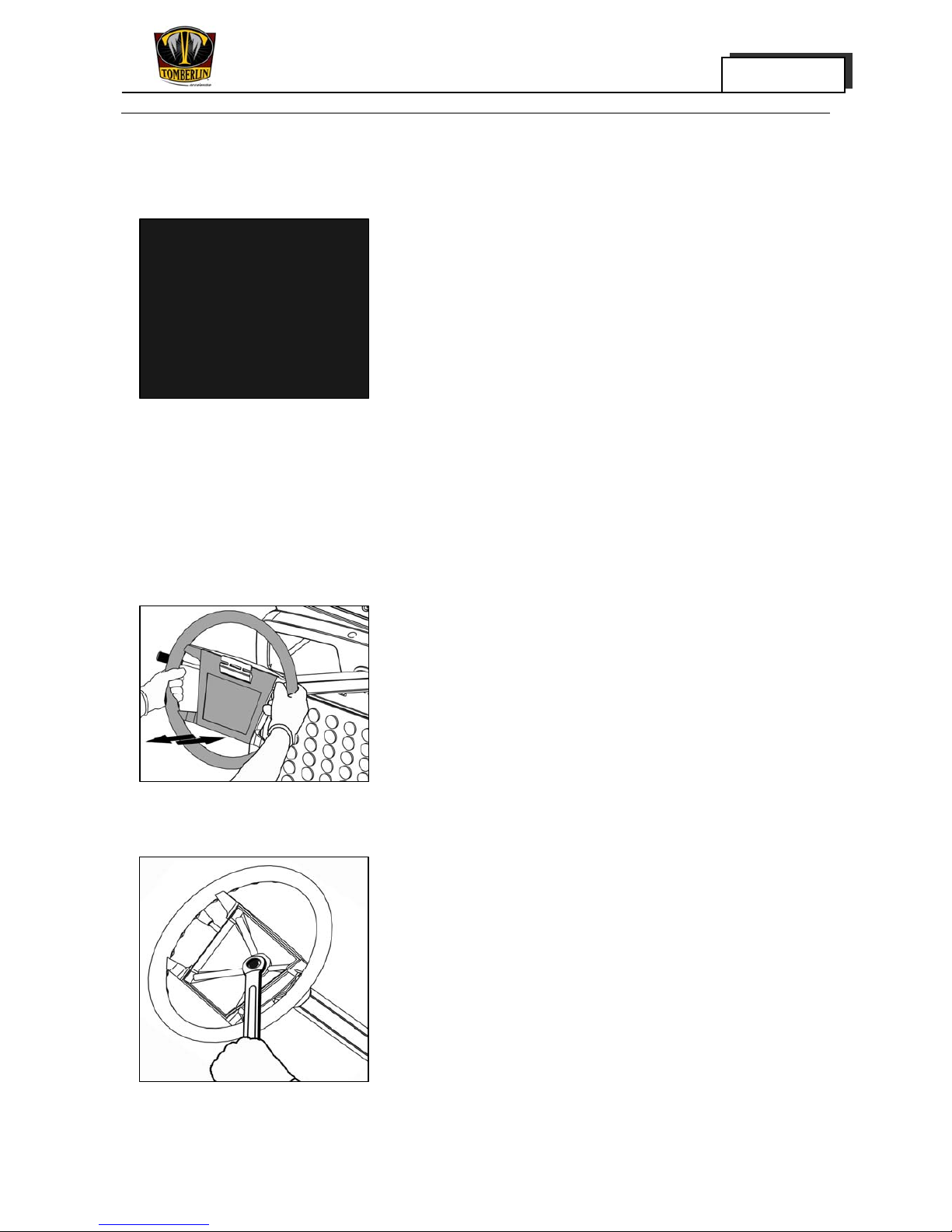
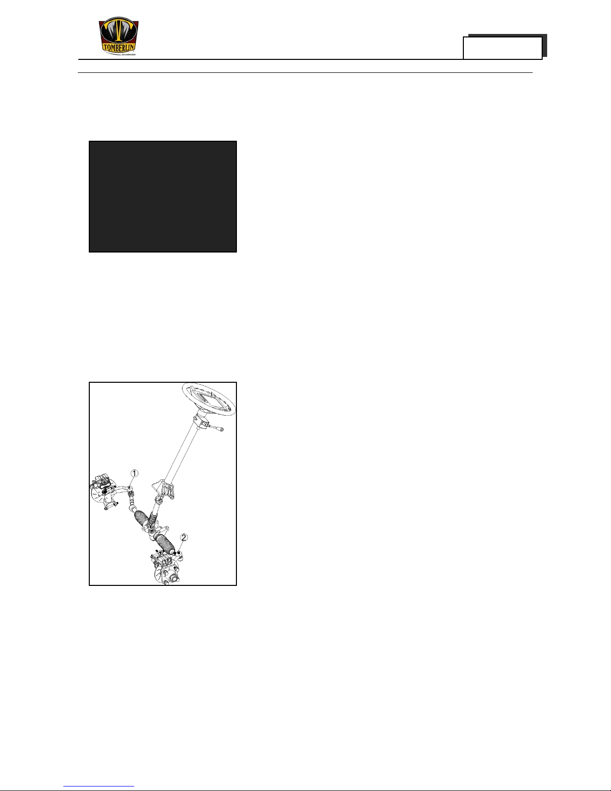
Inspection of the Steering System
State of the Steering Wheel in Steering Operation
1.Inspect:
Steering clearance
Push and pull or turn the steering wheel. In case of
over-looseness, the steering wheel or cross-pin type
joint bolts should be tightened.
Limit value to steering clearance of steering wheel:
5°(arc length:15.27mm)
2.Tighten:
Nuts (of steering wheel)
Tightening torque to
Regular Inspection and Adjustment
MERGE 2-10
Chapter 2
50N·m (36.9ft·1b)
And tighten:
Bolts (of universal joint)
Upper fixing bolt
Lower fixing bolt
Tightening torque to
22N·m (16.2ft·1b)
3.Re-inspect:
· Steering clearance
Inspection of the Steering Linkage
Removal of Tie Rod Ball Joint
2. Inspect:
Ball joints in the following conditions:
· Unsteady operation
· Over-loose free operation
· Bending or scrape
· Damage of dust boot
Refer to Chapter 8 "Steering System"
NOTICE:
In case of any of the above conditions, replace with
a new ball joint.
3. Install:
Steering Gearbox ball joint.
Regular Inspection and Adjustment
MERGE 2-11
Chapter 2
Inspection of Stub Axle
· Free gap of kingpin bolt, spacer and bushing
a. Park the vehicle on flat surface and apply
parking brake
b. Jack up the front wheels of vehicle
c. Move the wheels lightly
In case the free clearance is too large, the bushing is to
be replaced or the bearing clearance is to be adjusted.
Inspection of the Front Wheel Alignment
Toe-in
1. Park the vehicle on flat surface.
2. Push the vehicle straightly ahead for about 20 steps
to stabilize the suspension.
NOTICE:
Do not pull back the vehicle or step on the brake
pedal, as it will leads to changing of toe-in.
3. Measure:
· Toe-in
Empty:5~8mm (0.20~0.32in)
Full load:0-3mm (0in-0.118in)
In case of non-compliance with standard specified,
adjustment is to be made
Regular Inspection and Adjustment
MERGE 2-12
Chapter 2
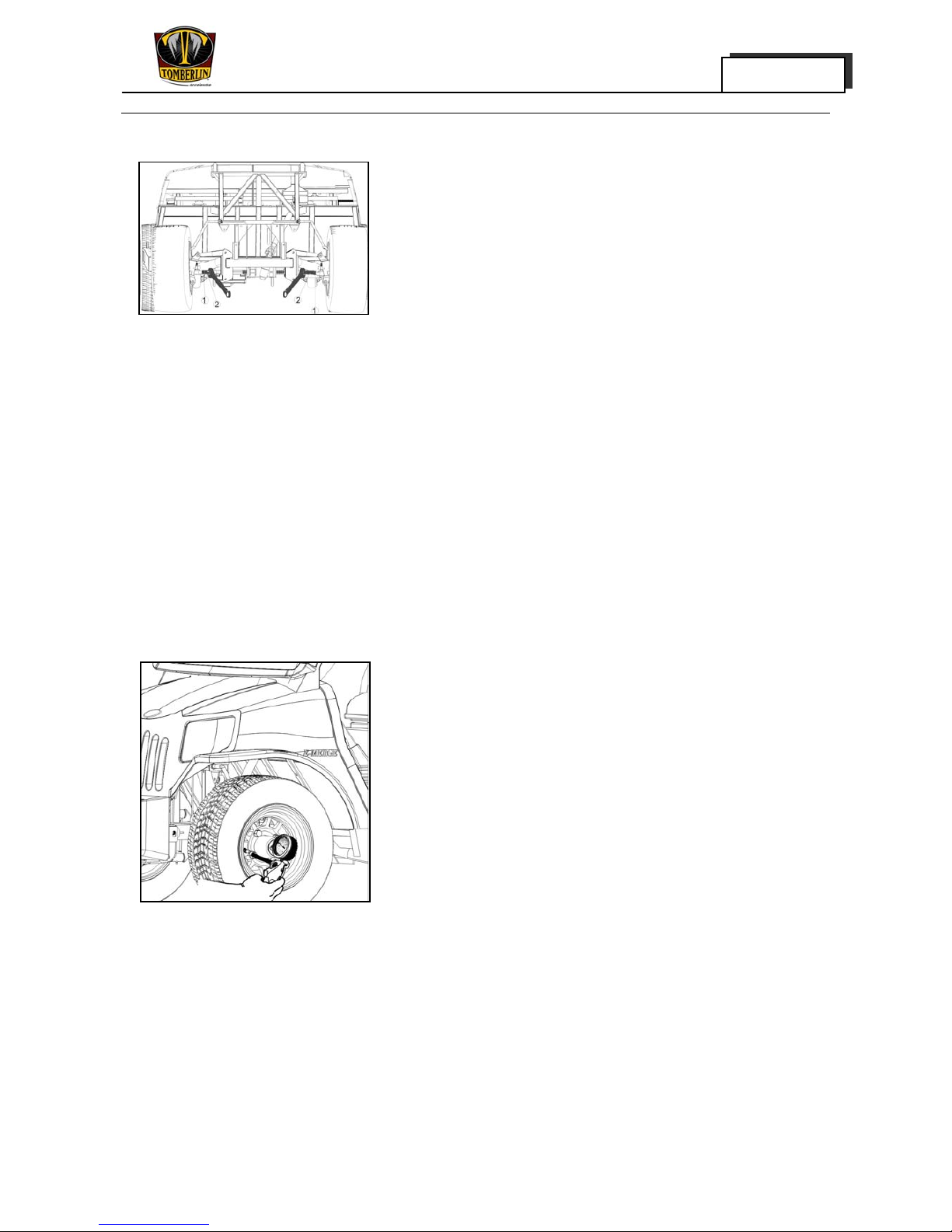
Procedures for the Adjustment of Toe-in:
· Park the vehicle on the flat surface and apply
parking brake.
Loosen the locknut(1) on the ends of the tie rod
Turn the steering tie rod to adjust the toe-in
increase→ rotate the steering tie rod so that the
length between two ball joints increases
Decrease→ rotate the steering tie rod so that the
length between two ball joints decreases (toe-in
decrease)
·
Tighten the locknut on the drag link ball joints.:
· Tightening torque to
40N·m (29.5ft·1b)
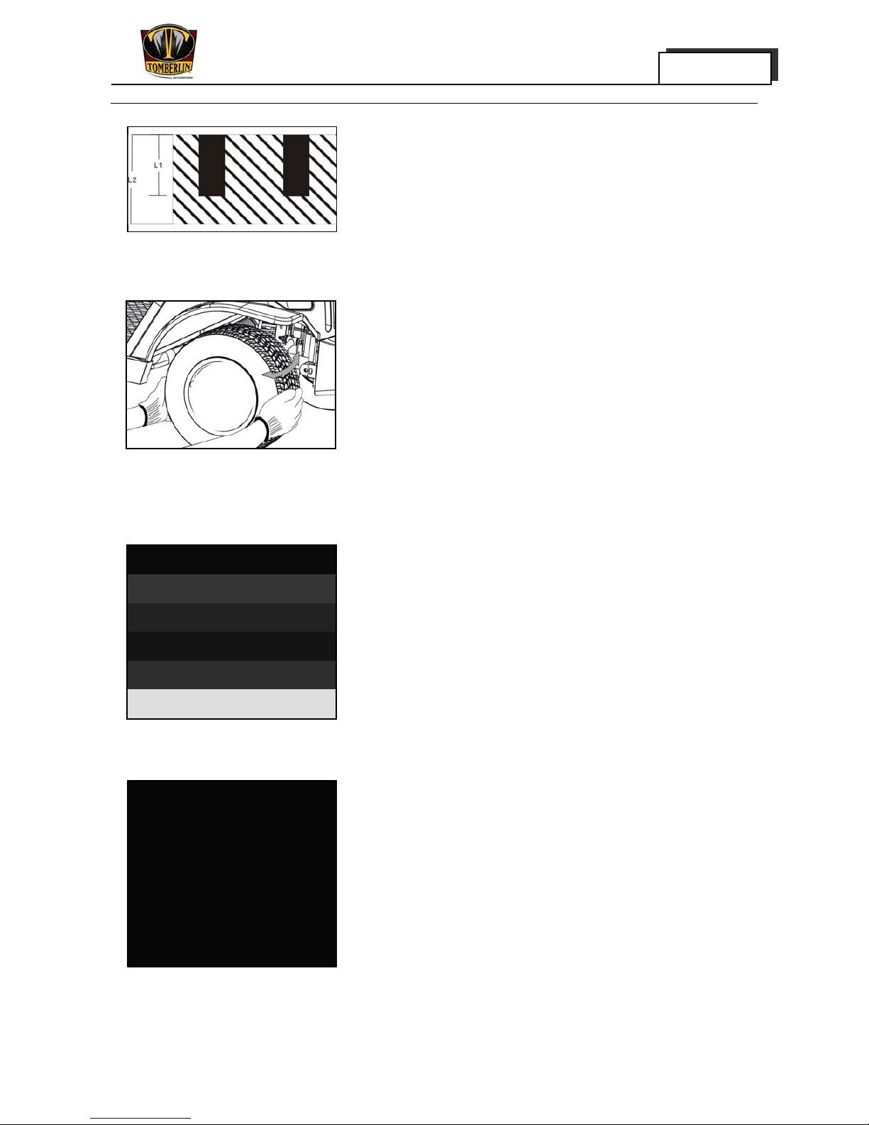
Inspection of Tires and Wheel Rim
1. Measure:
· Air pressure
In case of non-compliance with the standard,
adjustment is to be made
Tire pressure:(front and rear tires)
200-220kPa
Inspect:
· Tire surface
In case of any abrasion, damage, scrape or inset, the
tire is to be replaced.
· Wheel rim
In case of any damage or deformation, the rim is to be
replaced rather than go through the motions of
inspecting the wheel rim.
2. Measure:
Regular Inspection and Adjustment
MERGE 2-13
Chapter 2
· Wheel tread thickness
In case of non-compliance with the standard,
replacement is to be made
Maximum wearing value of wheel tread thickness
(front and rear tires) 4.0mm(0.16in)
Inspection of the Front Wheel Bearing
1. Wedge blocks onto the rear lower part of the rear
wheels and lift the front body with lifting jack.
2. Move front wheels by hand. Move the front wheel
with the Main Shaft being touched. In case the
clearance is too large, replace the bearing.
Inspection of the Rear Axle Bearing
1. Wedge blocks on the front lower part of the front
wheels, and loosen the rear wheel bolts.
2. Lift the rear body with the lifting jack.
3. Remove:
· Rear wheels
Brake drum
4. Slowly rotate by hand the half shaft of rear axle.
In case of unsmooth or unsteady rotation, the bearing
is to be replaced.
5. Lightly swing the half shaft of the rear axle. In case
that the free gap is too large, the bearing is to be
replaced.
NOTICE:
We do not recommend the replacement of bearing
and bearing sleeve as an individual part. During

Regular Inspection and Adjustment
MERGE 2-14
Chapter 2
the operation, the quality of fit between half shaft
and bearing or bearing sleeve may deteriorate. In
this case, we usually recommend the replacement of
a new rear axle half shaft assembly.
Inspection of the Shock Damper
1. Inspect:
· For oil leakage
In case of oil leakage, the shock damper is to be
replaced
· Spring
In case of decay, scrape or damage, the shock
damper is to be replaced
Mounting bolts of front shock damper:
Tightening torque
63N·m (46.5ft·1b)
Mounting bolts of the rear shock damper:
Tightening torque
63N·m (46.5ft·1b)
 Loading...