

Page 1

EXPLOSION-PROOF LED
3024XL, 3124XL SERIES
INSTALLATION, OPERATION AND MAINTENANCE DATA SHEET
IMPORTANT - Before installing, check the carton
label and fixture nameplate to be sure you have the
correct LED color and type of fixture. Read all
instructions before proceeding.
WARNING - Deactivate circuit before beginning
installation.
NOTE: All installations must comply with
applicable local and or National Electrical Code.
INSTALLATION:
1. Using the component drawing shown here,
remove the splice box from the fixture (if attached).
2. Refer to the splice box mount instruction sheet
K1087 included with the splice box. Install the
pendent mount splice box to the conduit and secure
with locking set screw. Install the ceiling mount using
four (4) external mounting screws.
NOTE: Fixture splice box must be grounded.
3. Remove the terminal block from the splice box by
loosening the two (2) mounting screws.
4. Connect the ground wire to the green screw inside
the base of the splice box.
OPERATIONAL DATA
Operate this fixture at its rated voltage. See fixture
nameplate for this data.
CAUTION: Disconnect the supplying circuit
before opening or reprogramming this fixture.
REPROGRAM FLASH RATE
Loosen the set screw, unscrew and remove the globe
support assembly.
Locate the DIP switch on the LED power supply at
the top center of the LED heatsink. CAUTION: Use
care not to disturb the LED wire harness. Change
the DIP switch pin settings as per the diagram.
Inspect the mating threads to be sure they are clean
and well lubricated. Inspect the globe for scratches.
NOTE: If the globe is scratched or chipped, the
globe support assembly must be replaced.
Reinstall the globe assembly.
When reprogramming, be careful not to damage the
external threaded areas, since they maintain the
fixtures explosion-proof properties. The threads
should be lubricated periodically.
5. Connect the supply lines to the terminal block.
(NOTE: For DC voltage the terminal block is to be
wired “POS” (+) to the “LINE” terminal and “NEG” (-)
to the “COM” or “WHITE” terminal.)
6. Reinstall the terminal block in the splice box, and
securely tighten it in place.
7. Thread the fixture into the splice box and secure
with the set screw. Be sure that the mating threads
are clean and adequately lubricated.
8. Check the tightness of all set screws and all
threaded joints. Turn on the supplying circuit to test
the fixture.
Save the installation instructions for maintenance
personnel.
IS0516-01
06-04-2013
Check the tightness of all set screws and all threaded
joints. Turn on the supplying circuit to test the fixture.
MAINTENANCE DATA
To maintain maximum light output from this fixture, it
should be cleaned periodically per the following
suggestions.
The aluminum exterior of the fixture should be
cleaned only with a mild soap or cleaner, and should
be rinsed with water immediately. Alkaline or acidic
cleaners should never be used on aluminum.
The glass globe may be cleaned with any nonabrasive cleaner. The globe should be regularly
inspected for scratches and chips.
These periodic cleaning procedures are important in
preventing the accumulation of dust and dirt which
will impair the light output of the fixture.
Page 2
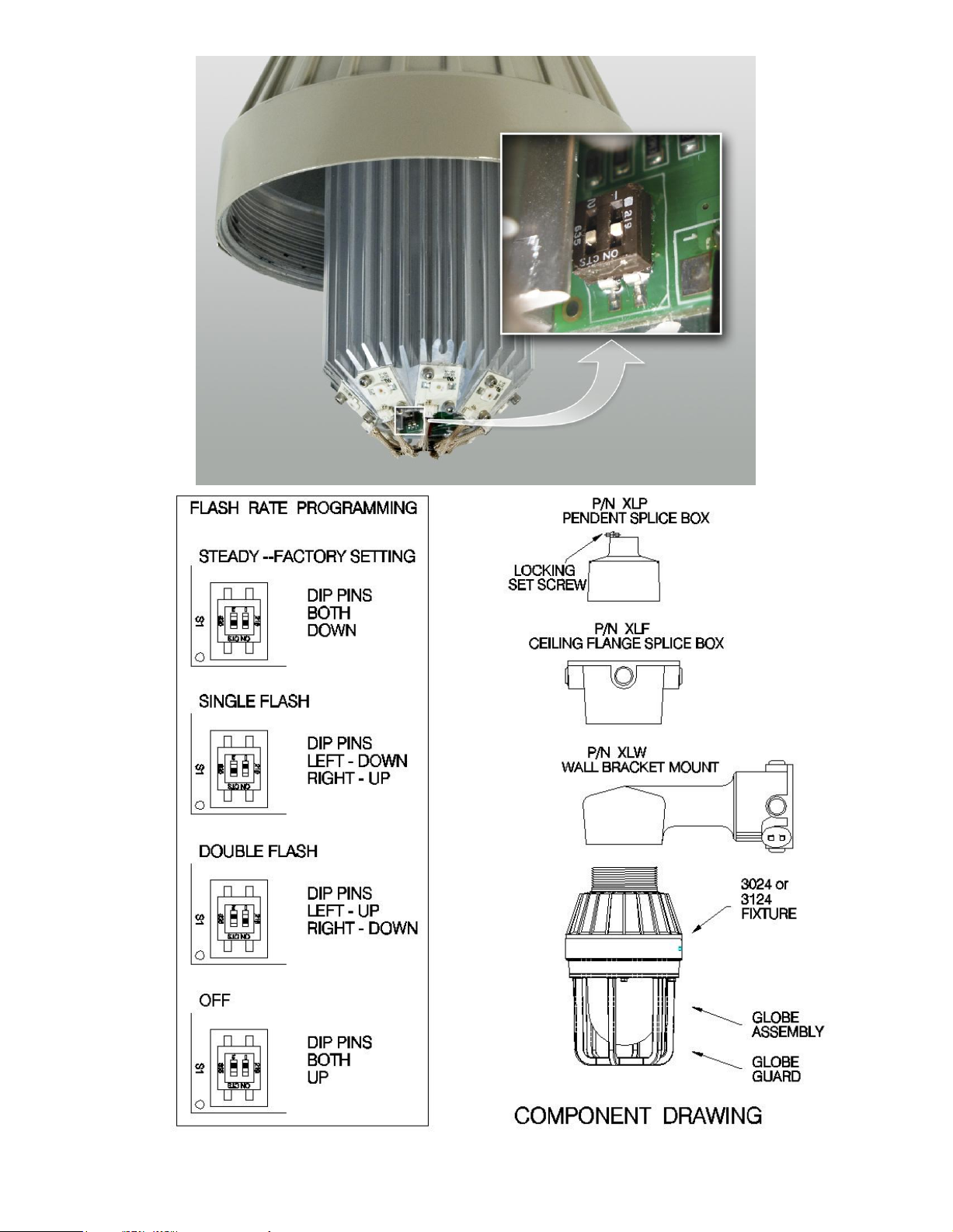
FLASH RATE PROGRAMMING SWITCH LOCATION
IS0516-01
06-04-2013
Page 3

IS0516-01
06-04-2013
 Loading...