

Page 1
IS0537-02
06/21/2013
Tomar Scorpion
TM
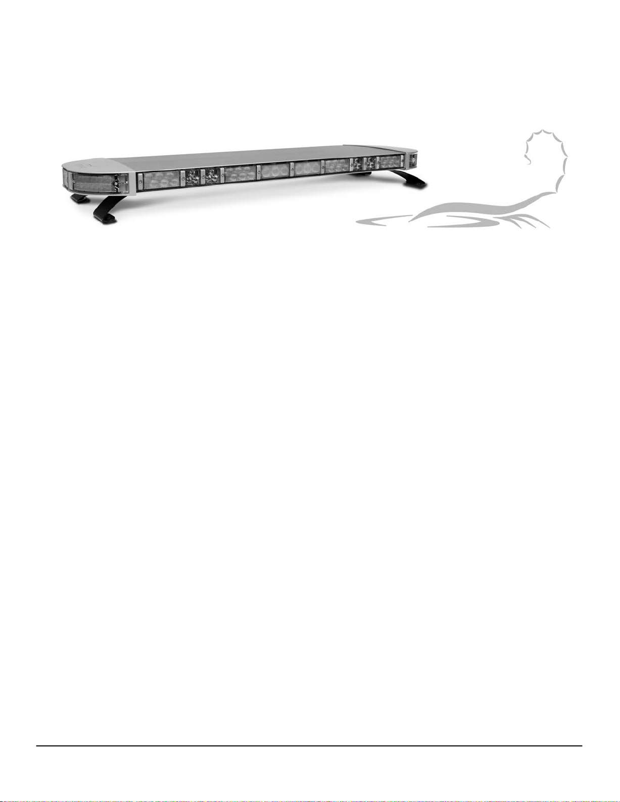
970L Lightbar
Operational & Programming Instructions
Programming Warning & Directional Modes Using The Lightbar Control Cable or The 94XDCP Digital Control Panels
The 970L Lightbar flash patterns may be custom programmed by using the Lightbar Control Cable, or by
using either of theTOMAR 94X-DCP Digital Control Panel or the TOMAR 94X-SIREN Siren Amp & Digital
Control Panels.
The 970L Lightbars have a wide variety of Flash Patterns built into the 970L-CONTROLLER. Using
EEPROM
CONTROLLER allows for independent programming of the Front, Rear, and Side Lamps. Factory set
patterns & a complete list of programmable patterns are detailed in Appendix A for the length of 970L
Lightbar you have ordered.
flash memory, the 970L-CONTROLLER can be reprogrammed many times. The 970L-
There are two ways to activate the control wires for the 970L lightbar. The first method is to control the
lightbar by using a progressive slide switch. The second method is to control the lightbar using independent
rocker
or on/off switches. Program the lightbar for all the individual and or wire combinations which will be
used in this installation.
Programming Warning Modes Using The Lightbar Control Cable
To activate the lightbar programming mode:
GROUND the 10 AWG BLACK power wire.
Apply +12vdc to the 12 AWG RED power wire & the GRN control wire.
Selecting the Warning Mode to Program
Apply +12vdc to program the desired Mode wire combinations, see the switching
examples
NOTE: All 7 possible combinations of the 3 warning mode wires (ORG, BLU, WHT/BLK) can be
programmed uniquely. If two or more wires are to be activated simultaneously, the wire combination must be
programmed as well. The last flash pattern programmed before exiting the programming mode becomes the
operational setting.
below.
2100 W OBISPO AVE
GILBERT, AZ 85233
WWW.TOMAR.COM
Page 1
PHONE: 800-338-3133
FAX: 800-688-6627
Page 2

IS0537-02
06/21/2013
Tomar Scorpion
TM
970L Lightbar
Operational & Programming Instructions
Example - Program Progressive Slide Switch Apply +12vdc to:
Mode 1 – ORG ORG
Mode 2 – ORG + BLU ORG + BLU
Mode 3 – ORG + BLU + WHT/BLK ORG + BLU + WHT/BLK
Example - Program Independent Switch Apply +12vdc to:
Mode 1 – ORG ORG
Mode 2 – BLU BLU
Mode 3 – WHT/BLK WHT/BLK
Advancing Selectable Warning Mode Patterns and Flash Rates
Once Warning Mode Programming has been entered and the Mode to be programmed activated, tap (apply
and remove) the appropriate wire to advance through the available ash patterns and ash rates. Continue
until the desired WARNING MODE AND FLASH RATE HAVE BEEN is selected.
Advancing Warning Pattern Selection:
Tapping the RED/WHT wire advances the REAR Warning Lamp patterns.
Tapping the BRN/WHT wire advances the FRONT Warning Lamp patterns.
Tapping the GRAY wire advances the SIDE Warning Lamp patterns.
Advancing Warning Flash Rate Selection:
Tapping the RED/WHT + WHT wire advances the REAR Flash Rate.
Tapping the BRN/WHT + WHT wire advances the FRONT Flash Rate.
Tapping the GRAY + WHT wire advances the SIDE Flash Rate.
Advancing Optional Features (if ordered):
These optional Steadyburn Light features can be programmed to be OFF or FLASHING in warning modes. In
normal operation, activation of a Steadyburn light overrides this warning mode.
Tapping the BRN wire toggles the Takedown Light between OFF and Flashing.
Tapping the VIO wire toggles the Rearwork Light between OFF and Flashing.
Tapping the YEL wire toggles the Alley Lights between OFF and Flashing.
Repeat for each Warning Mode wire and or combinations of Warning Mode wires.
To Exit Warning Mode Programming, remove power from all 970L power and control wires.
2100 W OBISPO AVE
GILBERT, AZ
85233
WWW.TOMAR.COM
Page 2
PHONE: 800-338-3133
FAX: 800-688-6627
Page 3

IS0537-02
06/21/2013
Tomar Scorpion
TM
970L Lightbar
Operational & Programming Instructions
Programming Directional Modes Using The Lightbar Control Cable
To activate the lightbar traffic direction programming mode:
GROUND the 10 AWG BLACK power wire.
Apply +12vdc to the 12 AWG RED power wire & the GRN control wire,
then apply +12vdc to the RED/WHT (Right Arrow) control wire.
NOTE: The Traffic Direction modes are (RED/WHT) Right Arrow, (BRN/WHT) Left Arrow and (RED/WHT +
BRN/WHT) Center Out. Only one Traffic Direction Mode, either Right Arrow or Left Arrow need be
programmed
six 970 LED modules are configured to the Rear of the 970L Lightbar.
Once Traffic Programming Mode has been entered, tap (apply and remove) the appropriate wire to advance
through the available traffic flash patterns and rates. Continue until the desired activation is selected.
Advancing Traffic Pattern Selection:
to program the Traffic Direction Modes. Traffic Direction modes are only available when at least
Tapping the WHT/BLK wire advances the DIRECTION patterns.
Advancing
Traffic Flash Rate Selection:
Tapping the WHT/BLK + WHT wire advances the DIRECTION Flash Rate.
To Exit Traffic Direction Mode Programming, remove power from all 970L power and control wires.
Programming Preemption Parking Brake Disable Function (Violet Wire)
GROUND the 10 AWG BLK power wire.
Apply +12 VDC to the 12 AWG RED power wire & the GRN control wire.
Advancing the function of the VIOLET disable wire
Tap the 18 AWG RED wire to scroll through the available settings. The strobe lamp will
pulse 1, 2, 3, or 4 times to indicate the function selected.
1 pulse of strobe = Ground
2 pulses of strobe = +12v
3 pulses of strobe = Ground Latch
4 pulses of strobe = +12v Latch
To activate the lightbar preemption parking break disable programming mode
2100 W OBISPO AVE
GILBERT, AZ 85233
WWW.TOMAR.COM
Page 3
PHONE: 800-338-3133
FAX: 800-688-6627
Page 4
IS0537-02
06/21/2013
Tomar 970L Scorpion Lightbar Programming Instructions
TM
Using one of the 94X-DCP Digital Control Panels or the 94X-Siren Amp & Control Panels
Connecting to the 970L LED Controller:
REMOVE POWER. Unscrew the lamp at the rear
passenger side of the Lightbar. Locate the 970L LED Controller and connect the DB9 receptacle of
the Tomar DB9-RJ45-Cable. Then connect the RJ-45 modular plug directly to the 94X-DCP, or the
94X-Siren Amp & Control Panel via the Slave RJ-45 port on the rear panel. If any Lightbar control
wires are connected by any other method then the 94X-Siren Amp & Control Panel -- DO NOT
activate any while in programming mode. Apply and maintain main power to the Lightbar.
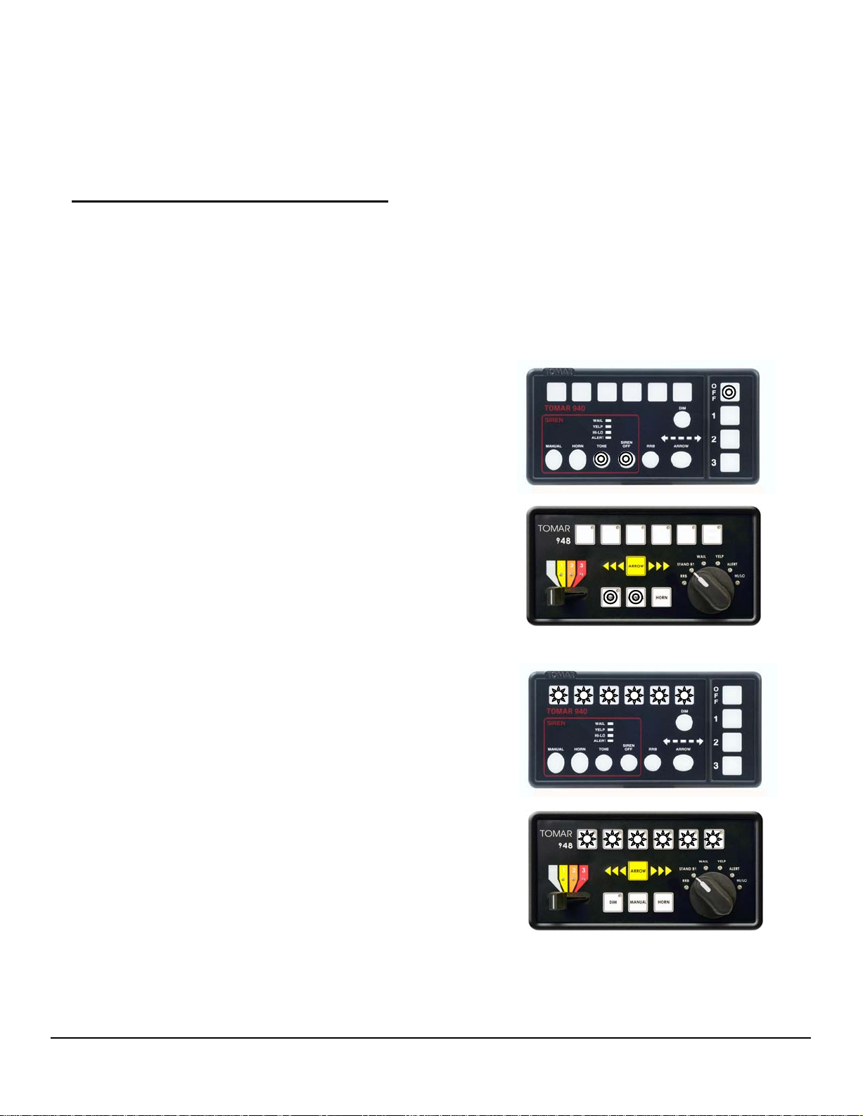
A. Activate Lightbar Programming Mode
1 2 3 4 5 6
940L - Activate the Lightbar Program Mode by
simultaneously pressing the TONE +
SIREN OFF + OFF switches and hold for
two seconds
948L - Activate the Lightbar Program Mode by
simultaneously pressing the MANUAL+
DIM switches and hold for two seconds
2. Programming switches 1-6 will blink three
times to indicate successful activation of
programming mode.
1 2 3 4 5 6
2100 W OBISPO AVE
GILBERT, AZ
85233
WWW.TOMAR.COM
Page 4
PHONE: 800-338-3133
FAX: 800-688-6627
Page 5
IS0537-02
06/21/2013
Tomar 970L Scorpion Lightbar Programming Instructions
TM
B. Programming Progressive Mode Switches
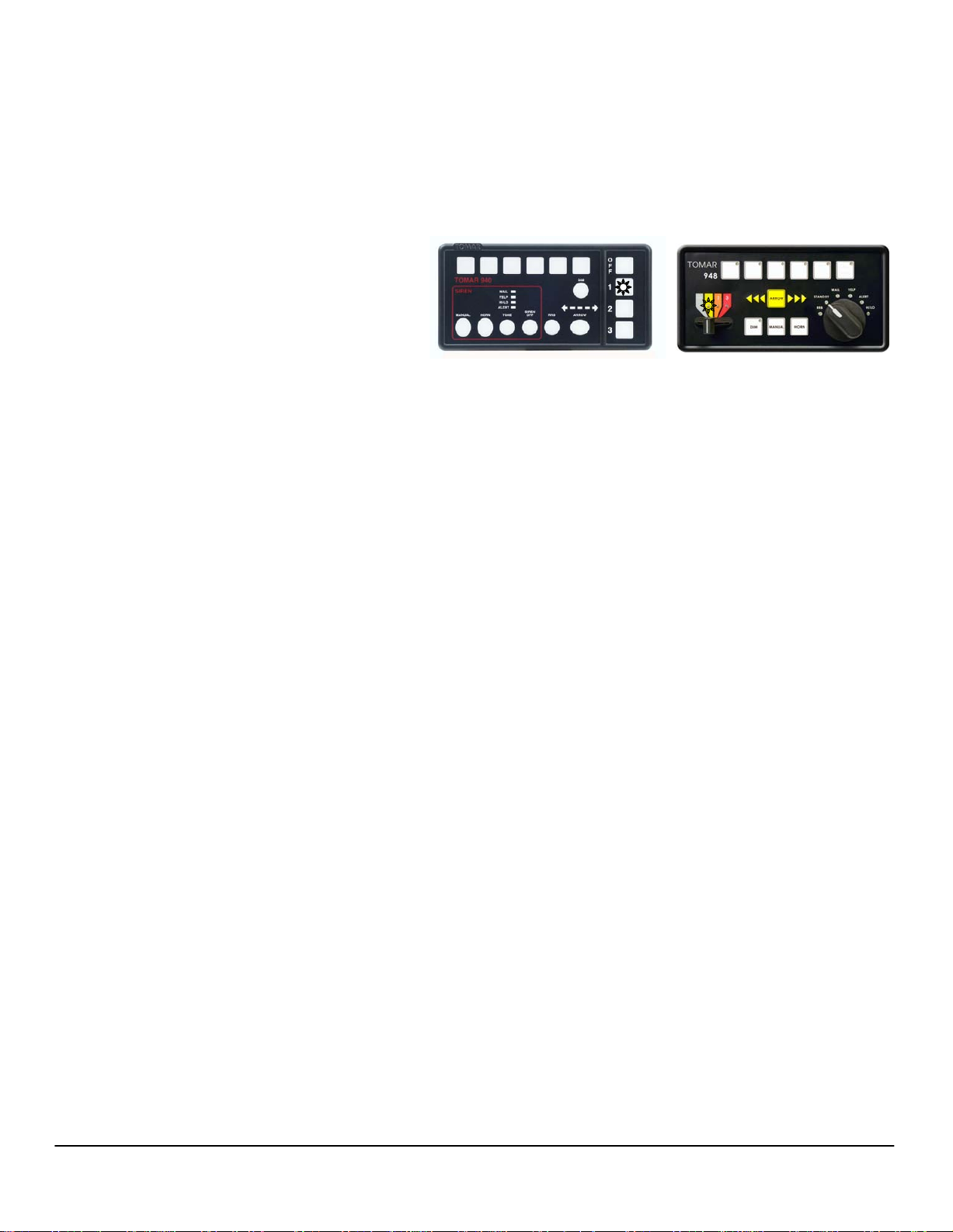
1. Program a Mode:
Example: Begin programming the Mode 1
warning pattern by pressing mode
Switch 1, or moving the slide switch to
position 1.
(a) Selecting Flash Pattern: Select the Mode 1 warning pattern by pressing the appropriate
switch as listed below. Each press advances the pattern one step. Continue until the desired
pattern is selected.
Pressing Programming switch 1 advances the Front Warning Lamps
Pressing Programming switch 3 advances the Rear Warning Lamps
Pressing Programming switch 5 advances the Side Warning Lamps
(b) Selecting Flash Rate: Select the Mode 1 ash rate by pressing the appropriate switch as
listed below. Each press advances the ash rate one step. Continue until the desired ash rate
is selected.
1 2 3 4 5 6
1 2 3 4 5 6
Pressing Programming switch 2 switch advances the Front Flash Rate
Pressing Programming switch 4 switch advances the Rear Flash Rate
Pressing Programming switch 6 switch advances the Side Flash Rate
(c) Selecting Flashing warning mode for Optional TD/RW/A Lights (if ordered):
To program, toggle the optional TD/RW/A Lights to be OFF or FLASHING in Warning Modes. In
normal operation, activation of a TD/RW/A light overrides this Flashing warning mode.
Press & hold DIM then press Programming switch 1 to toggle the Takedown Light (TD)
Press & hold DIM then press Programming switch 3 to toggle the Rearwork Light (RW)
Press & hold DIM then press Programming switch 5 to toggle the Alley Lights (A)
Repeat the above steps for each Warning mode; Mode 1, 2 & 3.
(d) Warning patterns and ash rates are now set for Mode s 1, 2 & 3 when selected.
2100 W OBISPO AVE
GILBERT, AZ
85233
WWW.TOMAR.COM
Page 5
PHONE: 800-338-3133
FAX: 800-688-6627
Page 6
IS0537-02
06/21/2013
Tomar 970L Scorpion Lightbar Programming Instructions
TM
C. Programming Traffic Direction Modes:
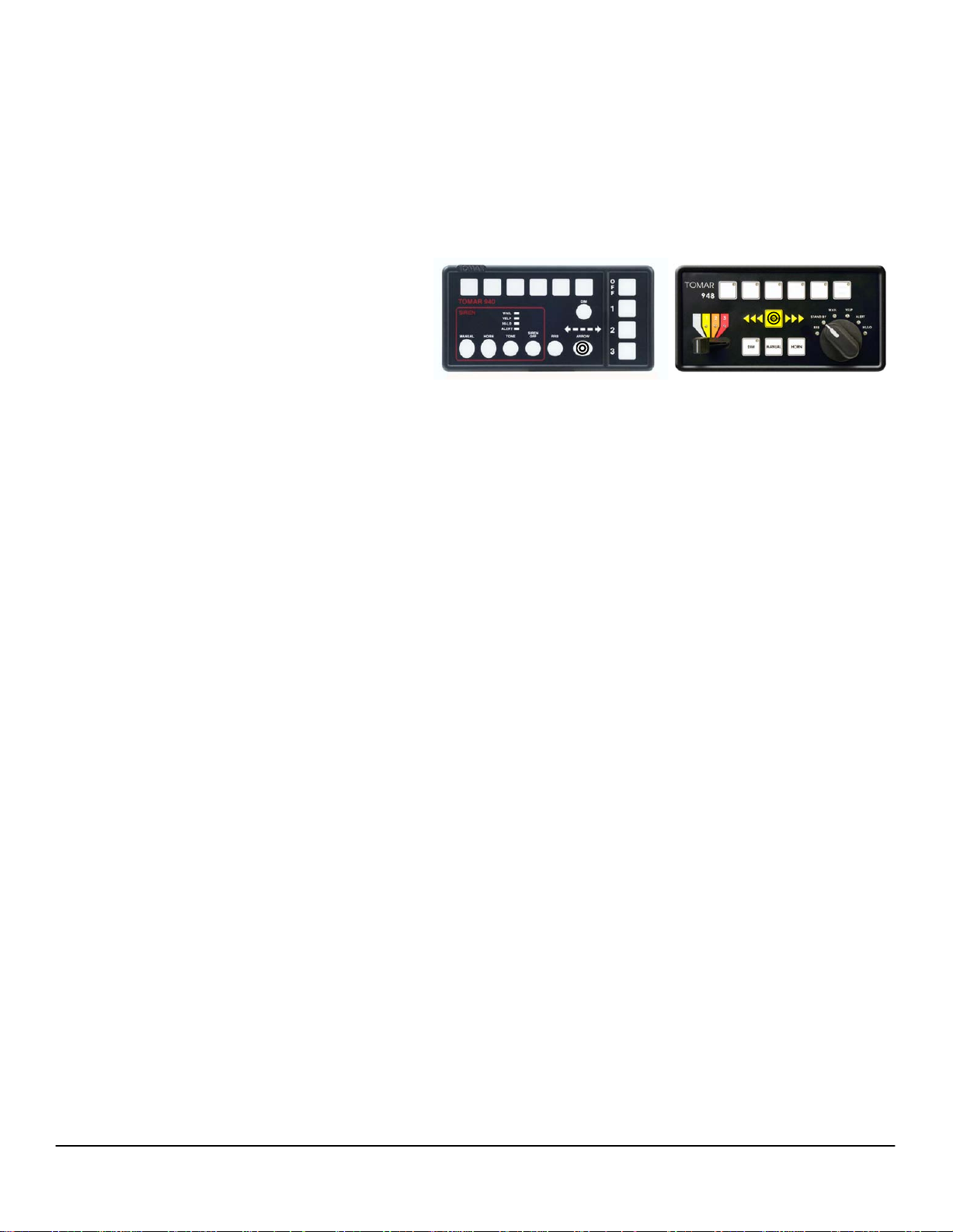
1. Program Rear Warning In Trac Direction
1 2 3 4 5 6
Modes: Select an arrow pattern by
pressing the Arrow switch
(a) Select Trac Direction Pattern by pressing Programming switch 1. Each press advances the
pattern one step. Continue until the desired pattern is selected.
(b) Selecting Trac Direction Flash Rate by pressing Programming switch 2. Each press advances
the ash rate one step. Continue until the desired ash rate is selected.
(c) Flash pattern and rate are now set for Trac Direction Mode when selected.
1 2 3 4 5 6
D.
EXIT 940L Programming Mode: Press the OFF switch TWICE, once to disable the Lightbar
once to
Press the MANUAL and DIM switches to exit program
EXIT 948L Programming Mode:
exit the 940L program mode.
mode on the 948L.
,
2100 W OBISPO AVE
GILBERT, AZ
85233
WWW.TOMAR.COM
Page 6
PHONE: 800-338-3133
FAX: 800-688-6627
 Loading...