

Page 1
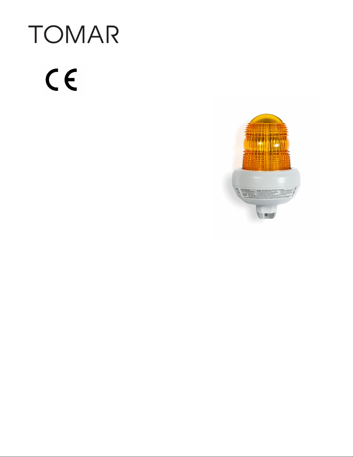
IS0589B-01
11/08/18
INSTALLATION, OPERATION
AND MAINTENANCE DATA SHEET
for MODEL 4375 and 4374 STROBE BEACONS
FOR CLASS I, DIV. 2, GROUPS ABCD
CLASS II, DIV 2 GROUPS F & G
HAZARDOUS LOCATIONS
SAFETY MESSAGE TO INSTALLERS, USERS, AND MAINTENANCE PERSONNEL
It is important to follow all instructions shipped with this product. This device is to be installed by a trained
installer who is thoroughly familiar with the national electrical code and local codes as well.
The selection of the mounting location for the device, its controls and the routing of the wiring is to be
accomplished under the direction of the facilities engineer. In addition, listed below are some other
important safety instructions and precaution you should follow:
• Read and understand all instructions before installing or operating this equipment.
• Do not connect this device to the system when the power is turned on.
• After installation, ensure that all screws and thread joints are properly tightened.
• After installation, test the system regularly to ensure that it is operating properly.
• After installation and testing is complete, provide a copy of this instruction sheet to all operating
Wiring the Beacon
The Model 4375 and 4374 Series strobe Beacons should be installed per the NEC or CEC, STATE and LOCAL
CODES, using a suitable wiring system for the specific hazardous location. Alternate installation locations
and/or orientations should only be performed with the approval of the authority having jurisdiction.
NOTE: The 120-240 VAC beacon is designed to operate on both 50 Hz and 60 Hz electrical power. Special
modifications are NOT required for either AC line frequency.
Page 2

Wiring the AC Models (4375S-120-240)
1. Ensure that power is off.
2. Install conduit to conduit opening and tighten set screw.
3. Pull field wiring through conduit into enclosure/base.
4. Remove threaded dome assembly by twisting it counterclockwise.
5. Loosen the printing wiring board (PWB) mounting screws and detach the PWB assembly to access
the lead wires.
6. Connect the black lead to the phase (hot) side of the power source and the white lead to the
common (neutral) side of the AC power source. Connect the green wire to ground.
7. Reattach the PWB assembly and secure the dome to the base of the beacon.
8. Connect power to the beacon and test it for proper operation.
Wiring DC Models (4375S-12-74)
1. Ensure that power is off.
2. Install conduit to conduit opening and tighten set screw.
3. Pull field wiring through conduit into enclosure/base.
4. Remove the threaded dome assembly by twisting it counterclockwise.
5. Loosen the printing wiring board (PWB) mounting screws and detach the PWB assembly to access
the lead wires.
6. Connect the red (+) lead to the positive side of the power source and the black (–) lead to the
negative side of power source. Connect the green wire to ground. Reattach the PWB assembly and
secure the dome to the base of the beacon.
7. Connect power to the beacon and test it for proper operation.
Wiring DC Supervisory Models (4374S-12-74) with four lead wires
1. Ensure that power is off.
2. Install conduit to conduit opening and tighten set screw.
3. Pull field wiring (five total including ground conductor) through conduit into enclosure/base.
4. Remove the threaded dome assembly by twisting it counterclockwise.
5. Loosen the printing wiring board (PWB) mounting screws and detach the PWB assembly to access
the lead wires.
6. Connect one red (+) lead to the positive side of the standard power source and one black (–) lead to
the negative side of the standard power source. Connect the green wire to ground. For supervisory
powering of the unit, connect the second red (+) lead to the supervisory positive power connection
and the second black (–) lead to the supervisory negative power connection.
7. Reattach the PWB assembly and secure the dome to the base of the beacon.
9. Connect power to the beacon and test it for proper operation.
EXPLOSION HAZARD—To reduce the risk of fire or explosion, do not install the beacon in a hazardous
location if the operating temperature exceeds the hazardous atmosphere’s ignition temperature. Before
proceeding, consult the product nameplate and determine the operating temperature of the beacon.
OPERATION
To operate the unit, just apply power. There are no adjustments to make for flash rate or intensity.
Page 3

IS0589B-01
09-11-18
SERVICE AND REPAIR
DANGER HIGH VOLTAGE
Should the light fail to operate, check to see that the proper voltage is reaching the unit. If the unit still fails to
operate, replace the lamp. To replace a lens or lamp, switch power off and wait 5 minutes before removing
lens.
WARNING - EXPLOSION HAZARD - SUBSTITUTION OF COMPONENTS MAY IMPAIR SUITABILITY
FOR CLASS I, DIVISION 2.
WARNING - EXPLOSION HAZARD - DO NOT DISCONNECT EQUIPMENT UNLESS POWER HAS BEEN
SWITCHED OFF OR THE AREA IS KNOWN TO BE NON - HAZARDOUS.
TOMAR Electronics, Inc.
2100 West Obispo • Gilbert, Arizona 85233 USA
800-338-3133 • (480) 497-4400 • FAX (480) 497-4416
 Loading...