

TOM Ultra XQ-U400H, Ultra XQ-U900H, Ultra XQ-U1600H Operation Manual

DIGITAL VIDEO RECORDER
OPERATION MANUAL (REV 1.0)
XQH - Ultra
Series
2
Safety precautions
Failure to follow these instructions could result in serious personal
injury or death.
Install this equipment avoiding a direct ray of light, heats and moistures.
-Doing not, can result in lowering efficiency, electric shock or fire.
Failure to follow these instructions could result in personal injury or
property damage.
Notifies user of references to use conveniently.
Do not pull electric wire or do not touch power plug with wet hands.
-Can result in electric shock or fire.
Do not bend the power cable forcedly or do not press it with heavy materials.
-Can result in electric shock or fire.
Do not use damaged power cord or loose outlet plug.
-Can result in electric shock or fire.
Do not use the outlet fully.
-Can result in electronic shock or fire.
Do not disassemble, repair or convert this product without permission.
-Can result in electric shock or fire. When repair is required, contact the service center.
D
o not open the cover of the product at your convenience or do not insert inductive stick
into the ventilation hole.
-Especially, SMPS is open, so only professional technicians are allowed to work on.
Do not place equipment on the inclined or uneven plane.
-Can cause lowering of efficiency or malfunction.
Do not vibrate or shock in operation.
-Can cause out of order with equipment and hard disk (HDD).
be caution that do not cover the ventilation hole of HDD or put liquid into the equipme nt.
-may cause out of order of equipment and hard disk drive (HDD)
Battery Caution : “Risk of Explosion if Battery is replaced by an Incorrect Type.
Dispose of Used Batteries According to the Instructions.”
3
Contents
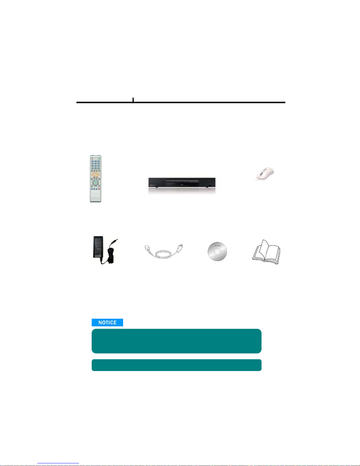
Open the box at the clean and even place. And read operation manual thoroughly before you install.
Remote Controller USB Mouse (option)
DVR Mainframe
Power Cord Set
Software CD
Operation Manual
DC Power Adapter
Check the items supplied with your DVR system. Refer to the picture above
and contact your dealer if you find anything is missing or damaged.
The specification and appearance may be changed without prior notice.

4
Index
Chapter I. System overview
System Specification ------------------------------------------------------------------------ 7
System Characte r i stics ---------------------------------------- --- --------------------------- 8
Chapter II. H/W description
System Appearance ------------------------------------- --- --- ----------------------------- 10
DVR Rear Panel --------------------------------------------------------------------------- 11, 12
System Rear Connection detail ------------------------------------------------------- 13, 14
System Front Description ------------------------------------------------------------ ----- 15
Remote Control Description ------------------------------------------------------------------- 16
Installation Guide for HDD disk --------------------------------------------------------------- 17
System on / shutdown -------------------------------------------------------------------------- 18
Chapter III. Monitoring Screen
Monitoring Screen --------------------------------------------------------------------------------20
Screen split, login ------------------------------ -------------------------------------------------- 21
Menu – Display ----------------------------------------------------------------------------------- 22
Menu – PTZ, Alarm --------------------------------------------------------------- --------------- 23
Menu – Status ------------------------------------------------------------------------------------- 24
Menu – Record, Camera, Color, OSD ------------------------------------------------------ 25
Menu – Backup ----------------------------------------------------------------------------------- 26
Menu – Mute, Logout --------------------------------------------------------------------------- 27
Chapt
erIV. Setup
System ---------------------------------------------------------------------------------------------- 29
System – Information -------------------------------------------------------------------------- 30
System – Date/Time --------------------------------------------------------------------------- 31
System – Disk ----------------------------------------------------------------------------------- 32
System – User ----------------------------------------------------------------------------------- 33
System – Log, Logout, Shutdown ----------------------------------------------------------34
Network ----------------------------------------------- ---------------------------------------------- 35
Network – LAN ---------------------------------------------------------------------------------- 36
Network – DDNS --------------------------------------------------------------------------------37
Network–Email ---------------------------------------------------------- ----------------------- 38
Network – Callback ---------------------------------------------------------------------------- 39
Device ----------------------------------------------------------------------------------------------- 40
Device – Camera ------------------------------------------------------------------------------- 41
Device – Alarm / Display ---------------------------------------------------------------------- 42
Device – Main Monitor ----------------------------------------- ------------------------------- 43
Device – Miscellaneous ----------------------------------------------------------------------- 44
Record ----------------------------------------------------------------------------------------------- 45
Record – Record policy / Data Retention ----------------- ------------------------------- 46
Record
–
Record Setup----------------------------------------------------------------------- 47
p
Event ------------------------------------------------------------------------------ ------------------- 48
Event – Motion ---------------------------------------------------------------------------------- 49
Event – Sensor ---------------------------------------------------------------------------------- 50
Event – Video loss ----------------------------------------------------------------------------- 51
Event – System --------------------------------------------------------------------------------- 52

5
Index
Chapter V. Search
Search screen ------------------------------------------------------------------------------------- 54
Menu – Display / Calendar search ---------------------------------------------------------- 55
------------------------------------------------------- --------
Menu
Section
/
Event
search
56
Menu – Date / Time search / First, Last, Bookmark ----------------------------------- 57
Menu – Advance Playback / Local device ------------------------------------------------ 58
Menu – Backup device ------------------------------------------------------------------------- 59
Chapter VI. Client program
REMOTE ------------------------------------------------------------------------------------------- 61
Connection Info / Button ----------------------------------------------------------------------- 62
Program Info & Setup --------------------------------------------------------------------------- 63
Icon Adjustment ---------------------------------------------------------------------------------- 64
Remote
search
execute
&
setup
---------------------------------------------- ---------------
65
Menu – Remote setup (Camera) ------------------------------------------------------------- 66
Menu – Remote setup (Alarm) --------------------------------------------------------------- 67
Menu – Remote setup (Main Monitor) ------------------------------------------------------ 68
Menu – Remote setup (Record) -------------------------------------------------------------- 69
Menu – Remote setup (Record table) ------------------------------------------------------ 70
Menu – Remote setup (Record policy) ----------------------------------------------------- 71
Menu – Remote setup (Motion) ------------------------------- ------------------------------- 72
Menu – Remote setup (Motion link) --------------------------------------------------------- 73
Menu – Remote setup (Sensor) -------------------------------------------------------------- 74
M
enu
–
R
emotesetup(Senso
r
link)
------------------------------------------------ --------
75
Menu – Remote setup (Video loss) --------------------------------------------------------- 76
Menu – Remote setup (Video loss link) ---------------------------------------------------- 77
Menu – Remote setup (Disk full / Disk full link) ------------------------------------------ 78
Menu – Remote setup (S.M.A.R.T / S.M.A.R.T link) ----------------------------------- 79
Menu – Remote setup (DDNS) --------------------------------------------------------------- 80
Menu – Remote setup (E-Mail) --------------------------------------------------------------- 81
Menu – Remote setup (Callback) ------------------------------------------------------------ 82
Menu – Remote setup (LAN) ------------------------------------------------------------- ---- 83
Play & Pause / Audio transmission / Mouse click to right ------------------------- 84
Channel button/Layout change button --------------------------------------------------- 85
PTZ operation ----------------------------------------------------------------------------------- 86
Remote search (Image playback screen / Section) ----------------------------------- 87
Remote search (Hotkey & Event search) ------------------------------------------------ 88
Remote search (Connection info / button / playback button) ----------------------- 89
Remote search (Split screen change / Audio / Image control button) ----------- 90
Remote search (Saving related button) -------------------------------------------------- 91
Remote search (Preview) -------------------------------------------------------------------- 92
Remote search (Mouse click to right) ----------------------------------------------------- 93
Remote search
(
Time table)----------------------------------------------------------------- 94
(
)
Backup playback -------------------------------------------------------------------------------- 95
PLAYER ------------------------------------------------------------------------------------ 96 ~ 98
Product Warranty ------------------------------------------------------------------------------- 99

6
Chapter-I. System Overview

7
XQ-U400H XQ-U900H XQ-U1600H
Chapter I
System Specification
Video IN / Loop Out
4/0 9/0 16/0
Video Display 1, 4 1, 4, 9 1, 4, 9, 16
Monitor Out
1CH Composite
VGA Out
1CH
Audio In/Out 4 in / 1 out
Audio Compression G.723
Display Resolution 720x480
Recording Resolution 720x480, 720x240, 360x240
Video Compression H.264
Display
Frame
NTSC 120fps 270fps 480fps
PAL 100fps 225fps 400fps
Record
Frame
NTSC 240fps 240fps 240fps
PAL 200fps 200fps 200fps
Playback
NTSC 240fps 240fps 240fps
Frame
PAL 200fps 200fps 200fps
OS Embedded Linux
Network
Interface 10/100 Base-T (1EA)
Transmission speed Max. 240fps
USB USB2.0 (Front 1EA, Rear 1EA)
HDD SATA 1CH
PTZ RS485
Alarm Function (In/Out)
4/1
Remote controller ID Remote controller
Watchdog / Power monitor Yes
Front LED Power, REC, HDD, Network
Dimension 350(W) x 215(D) x 50(H) mm
Operation temp. 0~45℃
Operation humidity 5~70%
Weight
1.6kg (Without HDD)
Power Adapter DC 12V 3A 50/60Hz

8
System Characteristics
¾ High quality video compression H.264 Codec
Chapter I
¾ Powerful 240fps Recording Performance – CIF (360x240) Base
¾ Max. 1 HDD built-in ( can support up to 1.5TB ) / SATA Type HDD support
¾ Frame rates, resolution and image quality adjustable for each camera separately
¾ User Friendly Control by USB Mouse, Remote Controller and Keyboard
¾ Maximized Security Efficiency by Live Image Edition, Digital Zoom(2x)
¾ Optimal Recording Mode with Event, Enforcement and Schedule Recording
¾ Various Search Engine Support like Time, Calendar and Event
¾ Multifarious Backup Device : Network Backup and USB 2.0 Device ( Memory Stick, USB HDD )
¾ DISK ID, S.M.A.R.T functions, real-time disk health check
¾10/100 Base-T network
¾ Strengthen Security Management by 9 Levels
¾ Multi-Language available
(English, Japanese, Chinese, French, Spanish, Portugu ese, Danish, Italian, Turkish, Polish,
Russian, Taiwanese and Korean )
¾ Various Network S/W Support for REMOTE, CMS, AGENT, PDA, WEB and 3G Phone
-
¾
Simultaneous Monitoring on 64CH, Max. 128CH Watching by Dual Monitor, e
MAP
,
Alarm & Event By CMS

9
Chapter-II. H/W Description
10
Chapter II
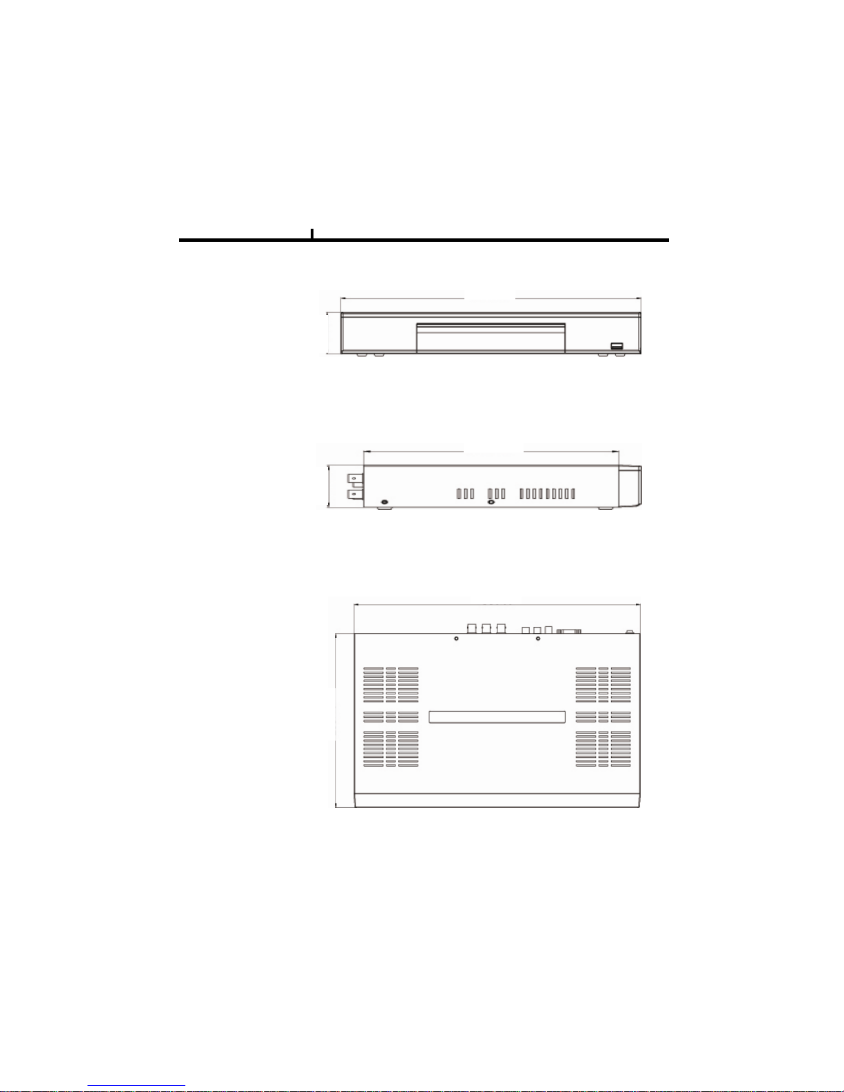
System appearance
350mm
1) Front View
48mm
2) Side View
196.3mm
48mm
350mm
3) Top View
213.4mm
11
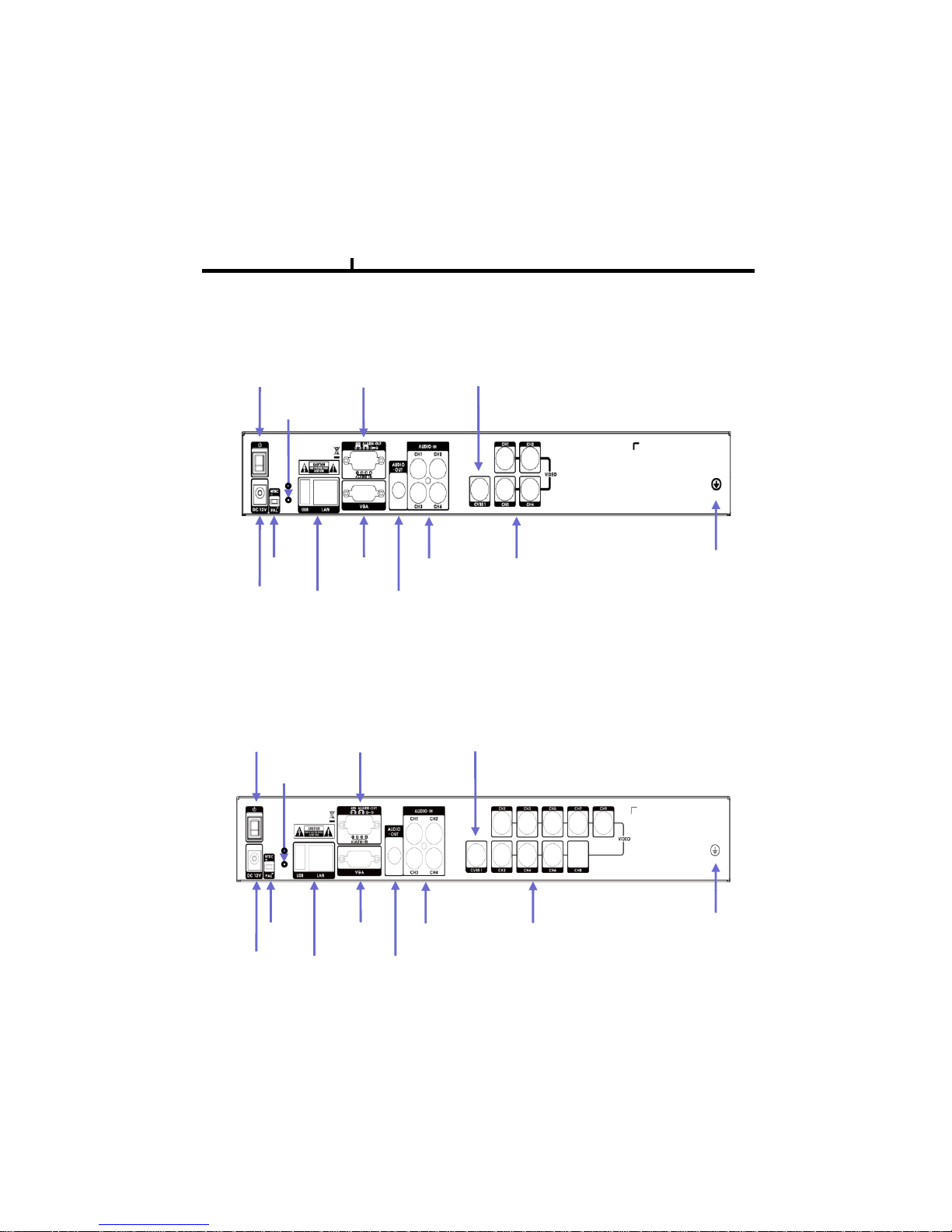
DVR Rear Panel
1) 4CH Rear Panel
Chapter II
Power
ON/OFF
Alarm In/Out,
RS485
Video Out
Factory
Default
Video In
4CH
GroundAudio In
4CH
Audio Out
VGA Port
Power In
USB/Network
NTSC/PAL
Switch
2) 9CH Rear Panel
DC 12V 3A
Port
Power
ON/OFF
Alarm In/Out,
RS485
Video Out
Factory
Default
Power In
DC 12V 3A
NTSC/PAL
Switch
USB/Network
Port
VGA Port
Audio Out
Audio In
4CH
Video in
9CH
Ground
12
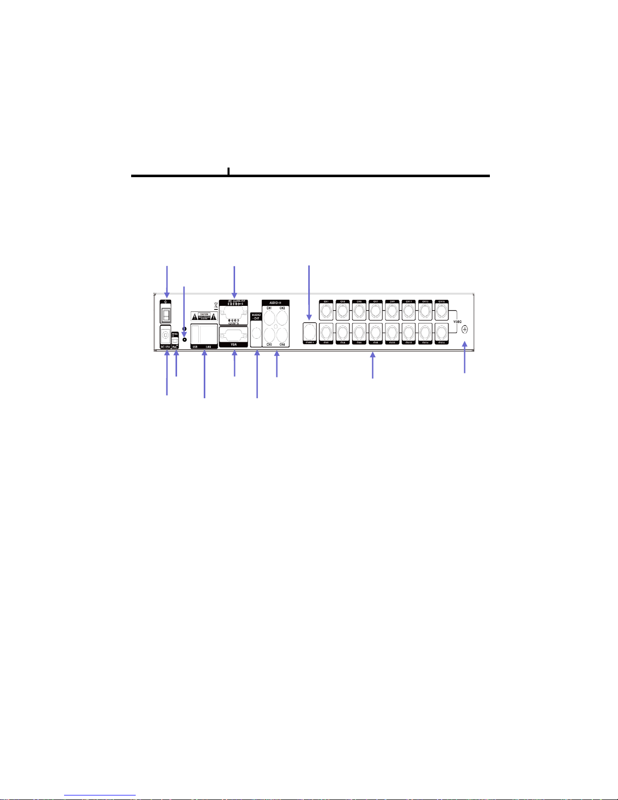
3) 16CH Rear Panel
Chapter II
Power
ON/OFF
Alarm In/Out,
RS485
Video Out
Factory
Default
NTSC/PAL
Switch
VGA Port Audio In
4CH
Video in
16CH
Ground
USB/Network
Port
Audio OutPower In
DC 12V 3A
13
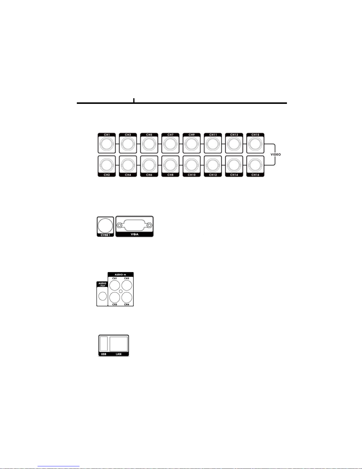
System rear connection detail
1) Video Source Connection
Chapter II
2) Monitor Connection
It connects video sources (camera image) to BNC connector via cable.
CVBS OUT : It connects normal CCTV CRT monitor.
VGA : It connects PC monitor or LCD monitor
(
not supporting DVI
)
It connects audio source (mic) to audio
(g)
3) Audio Connection
input of RCA and connects speaker to
audio output.
It supports 10/100 BaseT, connects
4) Network, USB Connection
Cat5 cable with RJ-45
Its supported devices are such as USB mouse, USB
external HDD and USB memory stick

14
Chapter II
5) NTSC/PAL Shift Switch
NTSC/PAL switch is used to adapt DVR to the User environment .
Make sure to switch the shift while DVR’s power is turned off.
After switching to the desired format turn on DVR again.
6) Alarm In (Sensor)/Out Connection and RS 485 connection
* Alarm Input 1~4CH
DVR is set to react to the Event through the External Device
Various Sensor and Switches (Signal, GND) can be connected
through this port
Ref. : Voltage level max. 6V/50mA
* Alarm Out 1CH
Th
e external devices
like Light, B
uzzer etc.
can be switched ON/OFF through this port.
Alarm Out Mode can be setup as Normal Open or Normal Close.
Ref. : Voltage level max24V/2A
* RS485
This Port supports Remote Control by Control Keyboard or
other external device through Half-duplex Serial.
Additionally , PTZ(Pan, Tilt, Zoom) camera can be controlled
throu
g
h this port.
gp
For connection to DVR’s RS485 +,- .
Power Supply is DC12V / 3A ; main power is changeable by ON/OFF switch.
7) Power Connection
8) Factory Default Button
Among 2 holes in the rear panel, the below one is factory default button,
while pushing the button and turn on DVR, it’ll become factory default mode.
15
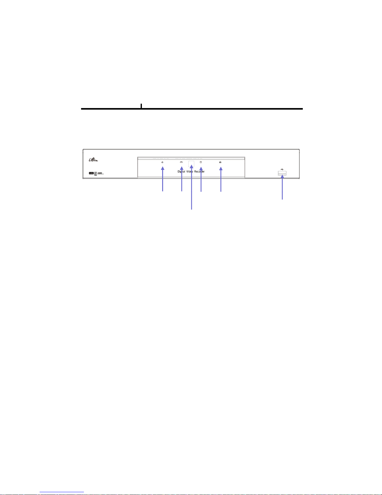
System Front Description
Chapter II
USB 2.0
Power
LED
Recording
LED
HDD
LED
Network
LED
Remote Controller IR Sensor
16
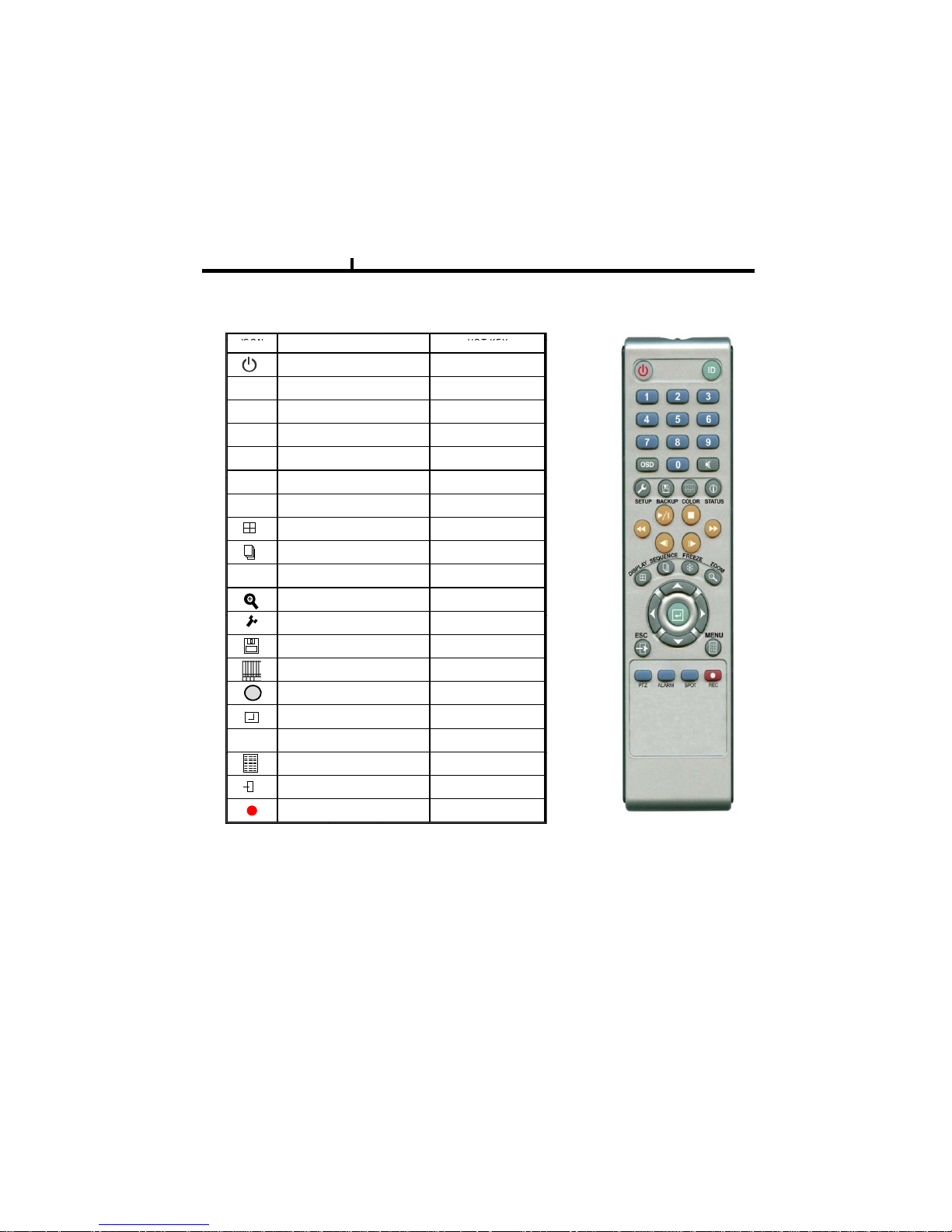
Remote controller Description (Optional)
Chapter II
ICON
HOT KEY
LATEST SEARCH
TO LIVE
FIRST SEARCH
LAST SEARCH
REWIND
FAST FORWORD
FUNCTION
POWER ON/OFF
PLAYBACK & PAUSE
STOP
||▶
■
◀◀
▶▶
CALENDAR SEARCH
EVEN T SEARCH
DISPLAY
SEQUENCE
FREEZE
ZOOM
STEP REVERSE
STEP FORWORD
◀|
|▶
7
SETUP
BACKUP
COLOR
STATUS
ENTER
DIRECTION
▲◀▶
▼
◀
1
i
○ How to change remote controller ID
A) Enter 'ID' button for 3seconds
RECORD
MENU
ESCAPE
▶
B) Power LED is lightened.
C) Enter 2 letters of digit. (00 ~ 99) – In case 00, means no ID function
- ID set is available from 01 to 99.
D) Save setting value, then LED is off.
E) It enables to communicate the same ID DVR
F) LED is ON every time data is transferred.
17
Chapter II
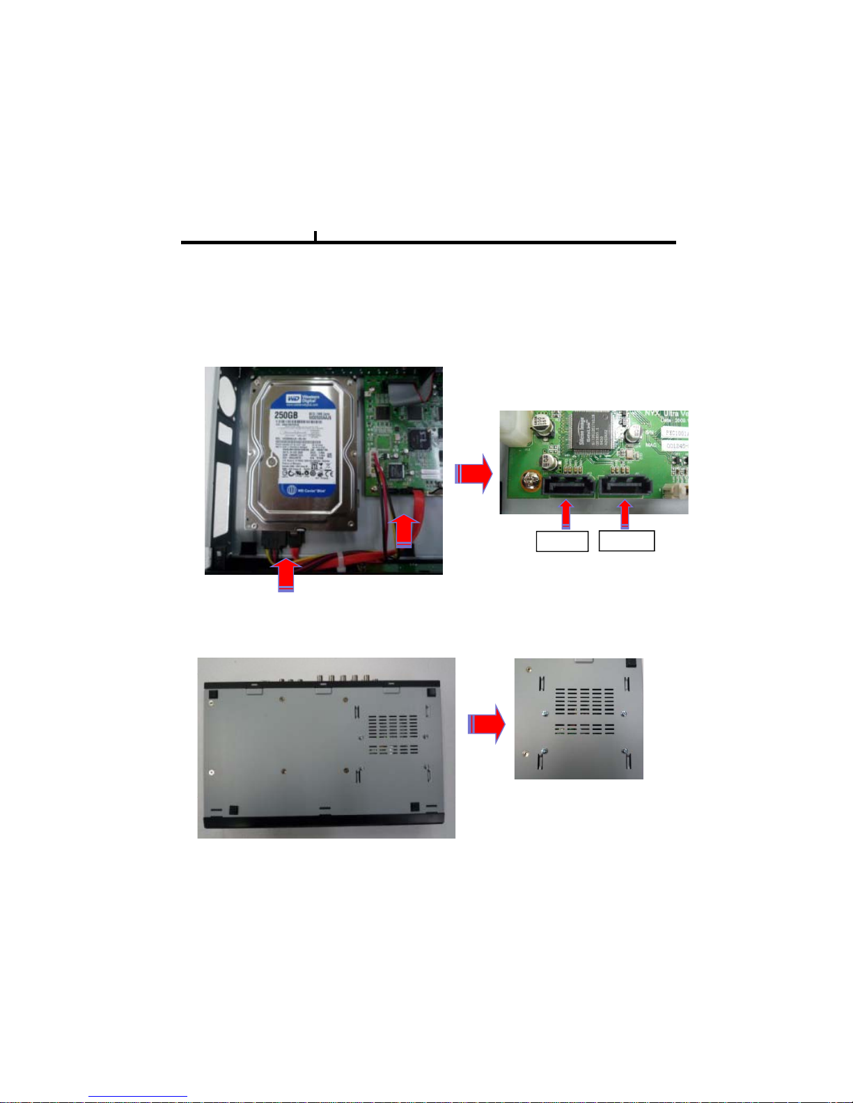
Installation Guide for HDD disk
Description
HDD for system needs to be installed as “SATA1”
SATA 1
SATA 2
( Product Inside )
Please fix HDD with 4pcs of screws.
( Product bottom side )
18
Chapter II
System On
• Put the power to the DVR.
•Turn on the power switch at the rear power button .
• It takes abou t 2minutes to boot (It may take more when network cable isn’t connected)
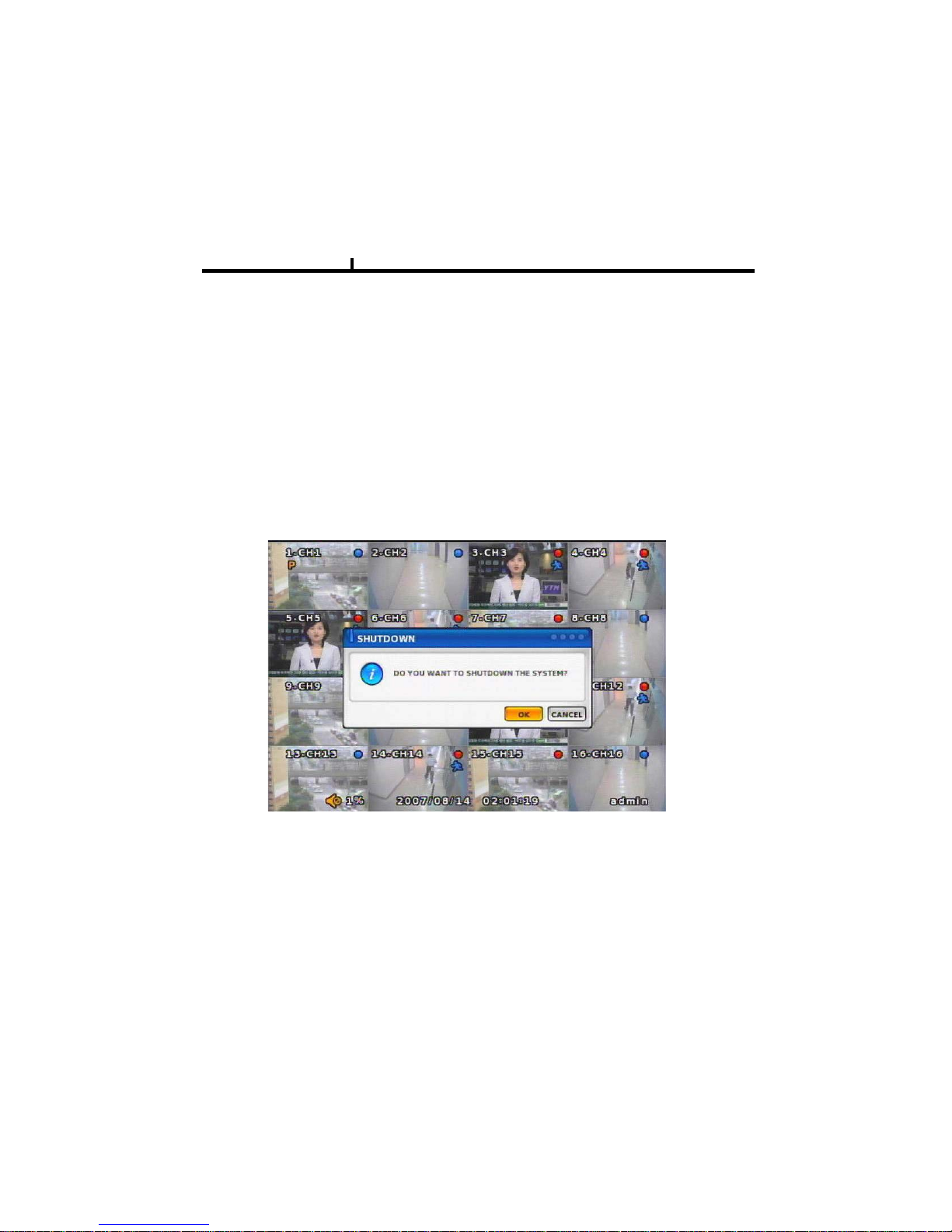
System Shutdown
•Select [SETUP > SYSTEM > SYSTEM SHUTDOWN] to shutdown system at login status
• Press “OK” butto n to confirm “Power off the system”, then turn off power switch in the rear.

19
Chapter-III. Monitoring Screen
20
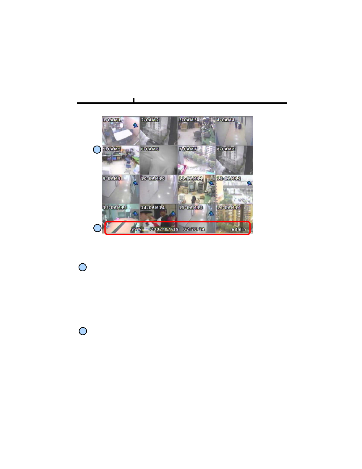
Monitoring Screen
Chapter III
1
2
Monitoring screen : it monitors each channel.
<Screen Indication>
Left Up : Camera Name
1
P –Pan/tilt
A – Audio
Right Up : Record mode (Blue-Normal, Red-Event)
Motion status
Central : Video Loss, Hidden Camera
Status Bar : DVR status Indication
2
(Backup, HDD usage, Current Time, SEQUENCE, FREEZE, Login info. etc)
21
Chapter III
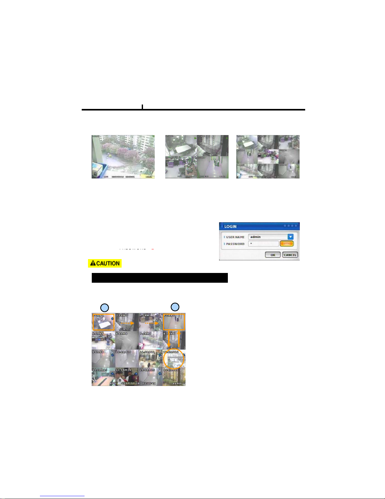
Screen Split
Press DISPLAY button or mouse menu: changed on 1 -> 4 -> 9 -> 16 by turn
Direct Channel
LOG IN
Login to menu for setup
Default: ID – admin
-
1) Press channel No. on the remote control or front panel.
2) Click the screen to watch specific channel using mouse.
** Pressing No.1 button responds a bit delayed to wait a possible signal input of
No.10~16 (approx 2.5 seconds)
It is recommended to change ID and PW for your safety.
PASSWORD
1
CAMERA ALLOCATION function (changing camera display position)
1
2
1) Press Enter in the monitoring screen, then
box is selected at No.1 camera.
2) Locate the box to the camera No. you want to
move using direction buttons.
3) Enter the camera number to switch
Ex) Switching camera No 4 and 12.
4) Then, selected camera is switched with the
Camera number you pressed.
5) To exit, press ESC or Enter
22
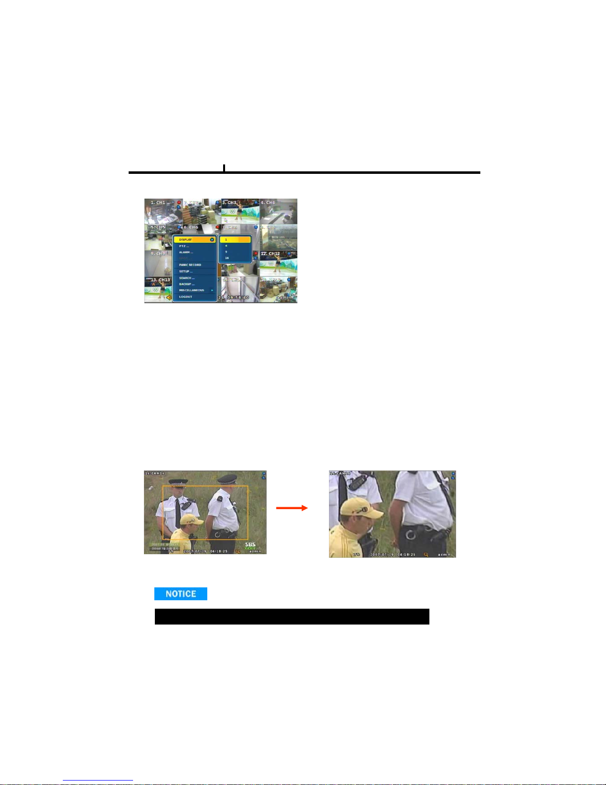
Menu Bar * Click MENU button or right button of mouse
Chapter III
DISPLAY
1, 4, 9, 16
: Split screen change (the same as DISPLAY button)
SEQUENCE
Sequence camera group regularly
FREEZE
MISCELLANUEOUS
ZOOM
1 Full Live screen available only.
Select Zoom : Press zoom button and locate the box to magnify using direction keys
Move Zoom : It can be moved using direction key after press Enter.
Pause the screen
Zoom screen may provide low quality or be shaken as formatted digitally.
<
ZOOM
selected screen>
<ZOOM
screen
>
23
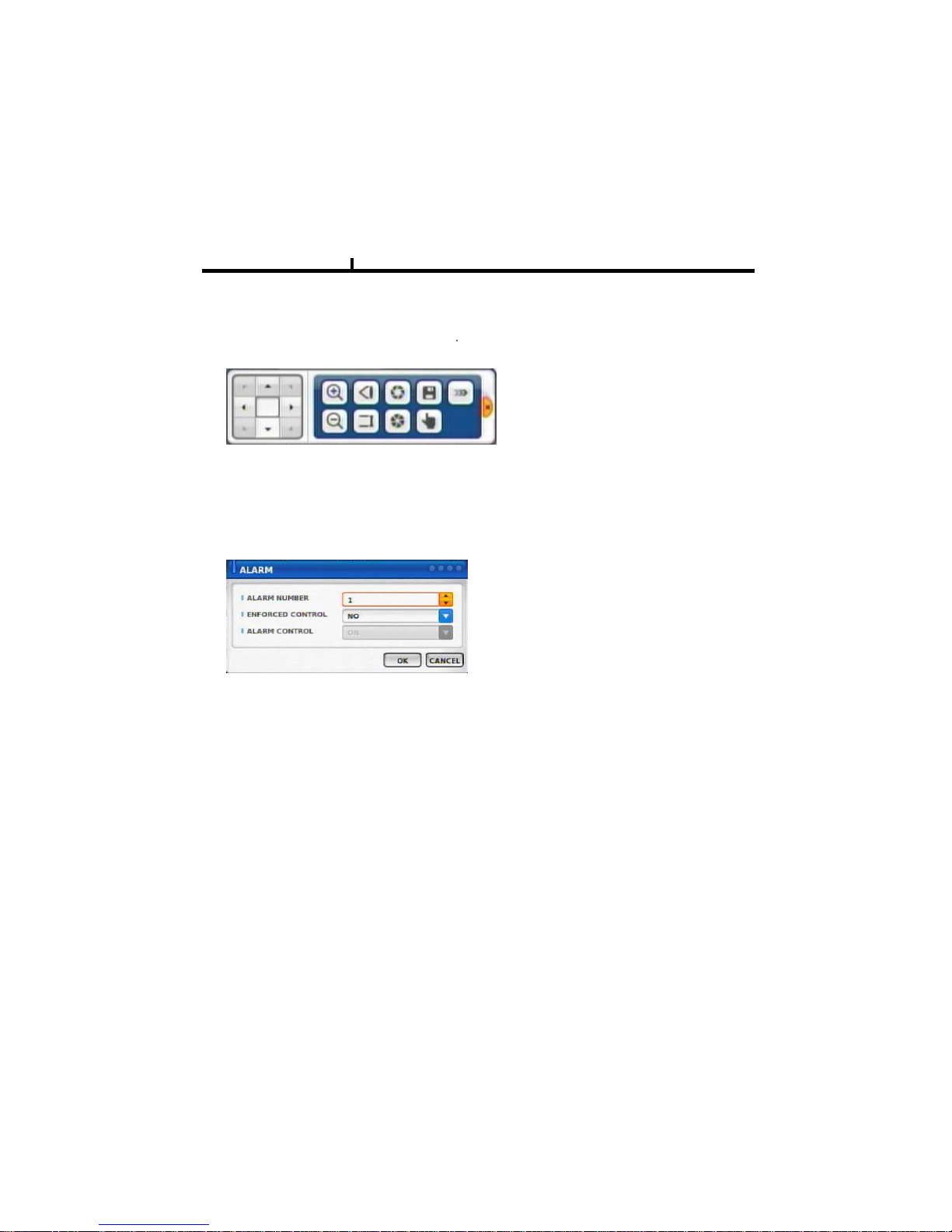
Chapter III
PTZ
Pan Tilt/Zoom/Focus/Iris Preset setting and moving functions are supported.
Each function can be different from each PTZ
p
rotocol.
p
ALARM
Control Alarm output function.
24
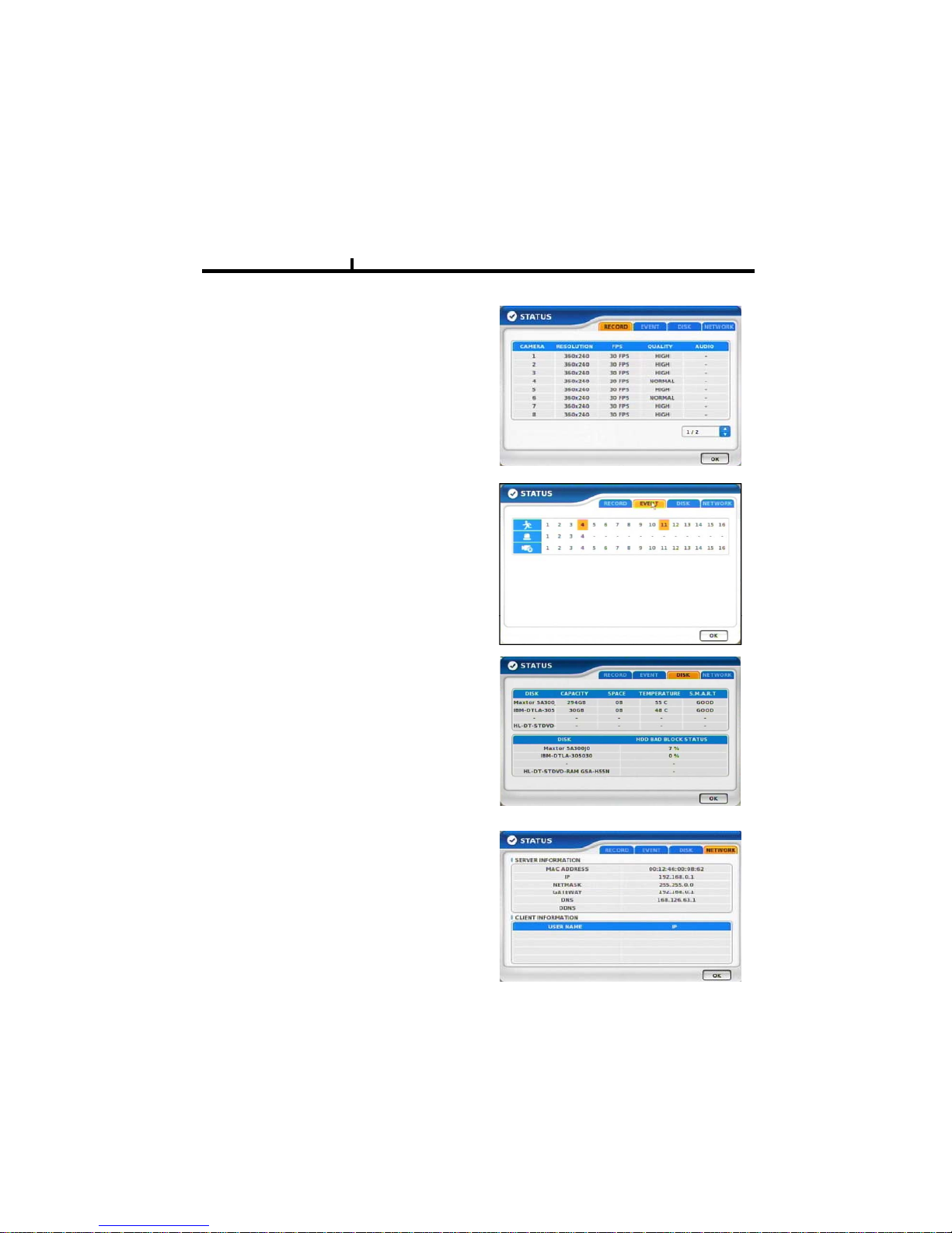
STATUS
Chapter III
RECORD
Displays current recording status
EVENT
Displays current event information (motion/alarm).
DISK
Displays current Disk information
Bad Block Status
NETWORK
Displays current network information.
Also displays current connected client information.
25
PANIC RECORD
Set recording mode in an emergency situation.
Press SETUP>RECORD> EVENT RECORD>FPS/QUALITY
Chapter III
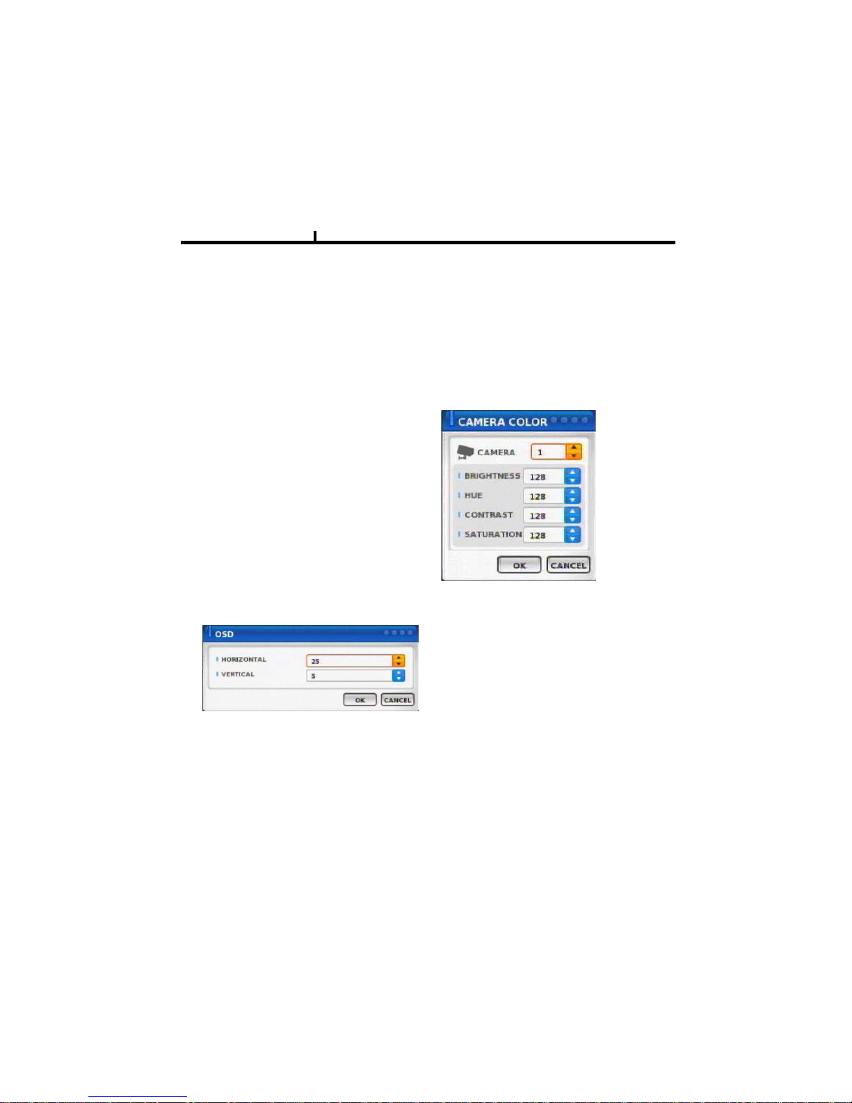
SETUP
Select to enter into SETUP menu
CAMERA COLOR
Changes camera screen color
OSD
Changes OSD (On Screen Display)’s position.
SEARCH
Select to enter into SEARCH menu
26
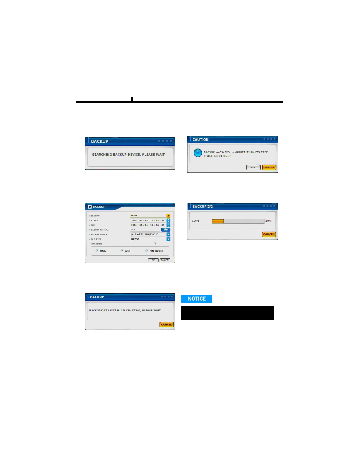
BACKUP
Select to backup recorded data.
Chapter III
1) Backup Device Search 4) Warning when data size is ove
r
2) Select data to backup 5) Make Image after pressing OK.
3) Calculate data size
During backup, any function won’t be
working due to system’s stability.

27
MUTE
Sound off
Chapter III
LOGOUT
Press SETUP>SYSTEM>USER

28
Chapter-IV. SETUP
29
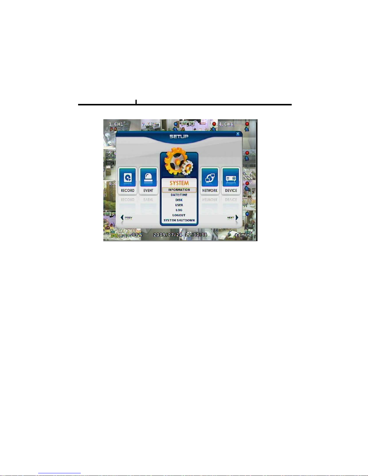
SETUP SCREEN
Chapter IV
SYSTEM
Set up various system related items.
INFORMATION
DATE/TIME
DISK
USER
LOG
LOGOUT
SYSTEM SHUTDOWN
30
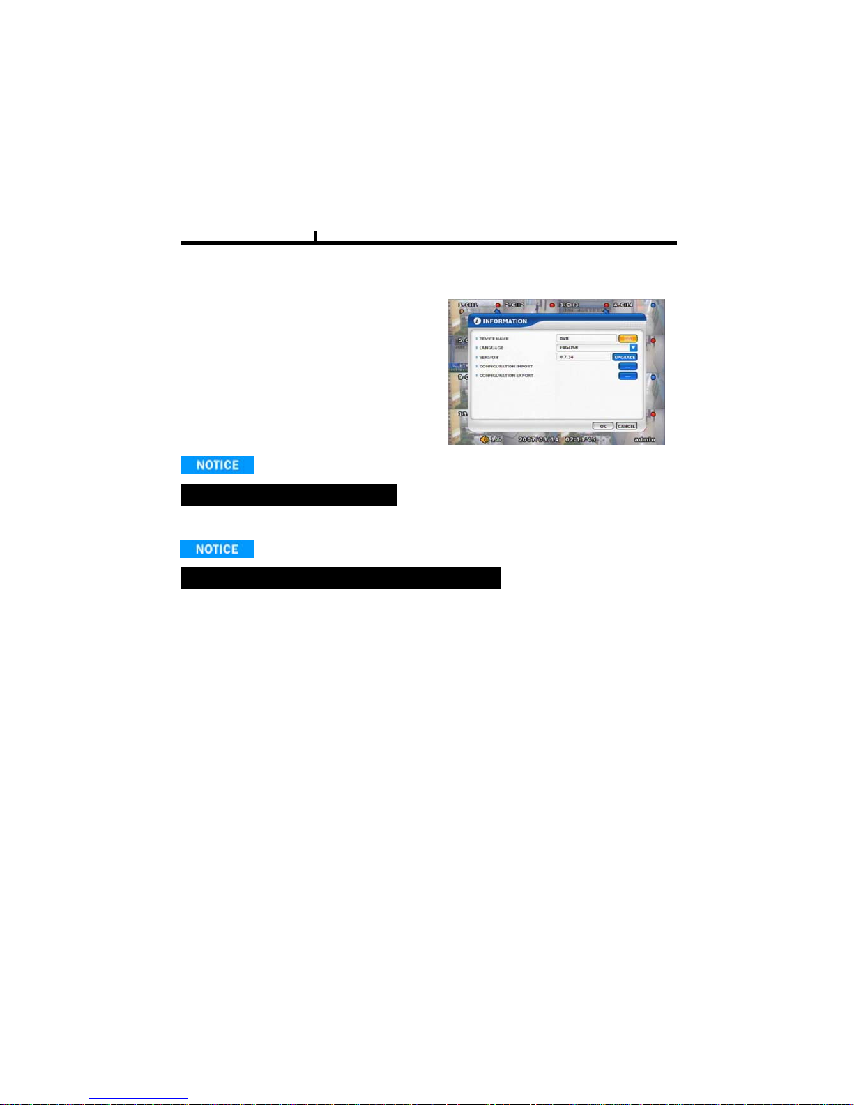
INFORMATION
Chapter IV
INFORMATION
DEVICE NAME: User can change the DVR
name on his own.
LANGUAGE : Select language.
VERSION : Shows S/W version info.
(With UPGRADE button, you can upgrade
the newest S/W version
)
)
Can’t upgrade when DVR’s power is on .
Contact manufacturer or distributors for upgraded versio n.
CONFIGURATION IMPORT : You can read setup values saved in USB or
Initialize the setup values
CONFIGURATION EXPORT :
You can record set
up
values in USB equipment
.
 Loading...