


ADMINISTRATORS GUIDE

2

bruAPP™ Backup Appliance Administratorʼs Guide
Made in U.S.A.
COPYRIGHT STATEMENT
TOLIS Group, Inc., et al
Copyright © 2001–2010 TOLIS Group, Inc. All rights reserved.
Your right to copy this manual is limited by copyright law. Making copies or adaptations without prior
written authorization from TOLIS Group, Inc. is prohibited by law and constitutes a punishable violation
of the law. To receive permission to reprint or copy information, contact tolispr@tolisgroup.com.
NOTICE OF TRADEMARKS AND SERVICE MARKS
BRU, bruAPP, bruAPP/OS, the TOLIS Group “three-man” Logo, the BRU “b” Logo, BRU Server, BRU
Server Agent, BRU Server Server, and BRU Server Console are trademarks or registered trademarks
of TOLIS Group, Inc.
“Backup You Can Trust” and “Because Itʼs the Restore that Matters” are service marks of TOLIS Group,
Inc.
The absence of a product, service name or logo from this list does not constitute a waiver of TOLIS
Group's trademark or other intellectual property rights concerning that product, service name or logo.
Throughout this manual trademarks are used. TOLIS Group, Inc. states that we are using any and all
trademarked names in an editorial fashion and to the benefit of the trademark owner with no intention of
infringement of the trademark. For TOLIS Group legal information, please contact
brulegal@tolisgroup.com.
NOTICE OF LIABILITY
The information in this manual is distributed “as is” and without warranty. While every precaution has
been taken in the preparation of this book, TOLIS Group, Inc. nor its resellers and representatives shall
have any liability to any person or entity with respect to any loss or damage caused or alleged to be
caused directly or indirectly by the information and instructions contained in this manual or by the
computer software and hardware described within.
TOLIS Group, Inc. may revise this publication from time to time without notice.
UPDATE INFORMATION
TOLIS Group, Inc. will always work to ensure that the data contained in this manual is kept up to date.
As such, please visit our website at http://www.tolisgroup.com to retrieve the latest version of this
manual.
PRINTING HISTORY
" May 2004:" " First Edition
" August 2008:" " Second Edition
" October 2010:" " Third Edition
" November 2010:" Fourth Edition
3

4

Table Of Contents
...............................................................................bruAPP/OS USB Update Drive 9
........................................................................................3U Chassis SAS Devices 9
.......................................................................................2 - Thank you!" 10
....................................................................................Contact TOLIS Group, Inc. 10
...........................................................................................................General Inquiries 10
.....................................................................................................................BRU Sales 10
..........................................................................................................Technical Support 10
......................................................................................Feature Requests & Feedback 10
....................................................................3 - bruAPP Box Contents" 11
.................................................................................................Initial Connections 12
.....................................................................................Connecting a Tape Device 12
...............................................................................................SCSI Tape Devices 13
......................................................1 - Important Warranty Information" 9
....................................................................Removing the bruAPP Chassis Cover 9
.............................................................................Non-TOLIS Group USB Devices 9
...........................................................................Non-Warranty Repair Information 9
..................................................................Shipment Packaging Required for RMA 9
.........................................................4 - Installation and Connections" 12
................................................................................3U Chassis SAS Tape Connection 12
.........................................................................Fibre-Channel (FC) Tape Devices 13
.............................................................................5 - Rack Installation" 14
.............................................................Identifying the Sections of the Rack Rails 14
...............................................................................Installing the Rear Inner Rails 14
........................................................................................Installing the Rack Rails 15
............................................................Installing the 1U/3U bruAPP into the Rack 15
...........................................................Installing the 1U bruAPP into a Telco Rack 15
...........................................................Installing the 3U bruAPP into a Telco Rack 16
.............................................................................Rack Mounting Considerations 16
..........................................................................................................Rack Precautions 16
........................................................................................................Server Precautions 16
....................................................................................Ambient Operating Temperature 16
............................................................................................................Reduced Airflow 17
.......................................................................................................Mechanical Loading 17
........................................................................................................Circuit Overloading 17
.............................................................................................................Reliable Ground 17
.............................................................6 - Powering On Your bruAPP" 18
......................................................................................................Tower Systems 18
........................................................................................1U Rackmount Systems 18
........................................................................................3U Rackmount Systems 19
........................................................................7 - Initial Configuration" 20
.......................................................................................................Network Setup 20
..............................................................................................Configure Ethernet Port 0 20
..............................................................................................Configure Ethernet Port 1 22
.................................................................................................Apply Network Settings 22
5

.........................................................................................Setting the Date & Time 22
...................................................................................................................Set the Date 22
.............................................................................................................Setting the Time 23
...................................................................................................Manually Set the Time 23
............................................................................................Automatically Set the Time 23
.....................................................................Applying the System Date & Time ― NTP 24
..............................................................................Setting the RAID Administrator 25
.......................................................................RAID Administrator SMTP Configuration 25
....................................................................Setting the bruAPP Admin Password 25
....................................................................Performing the Initial Hardware Scan 26
.................................................................................................Final Step: Reboot 27
.....................................................................................Setup BRU Server Agents 27
..........................................................................8 - Additional Options" 28
.........................................................................................bruAPP/OS Main Menu 28
.......................................................................................................Support Information 28
..............................................................................................................System Reboot 28
...........................................................................................................System Poweroff 28
.........................................................................................BRU Server Main Menu 28
.....................................................................................................bruAPP Stage Status 28
..............................................................................................BRU Server Text Console 29
..........................................................................................BRU Server Hardware Scan 30
...................................................................................BRU Server Agent Configuration 31
........................................................................................BRU Server Daemon Restart 31
...................................................................BRU Server License & Version Information 31
...........................................................................................Update License Information 32
.........................................................................................................Change Password 32
..................................................................................System Configuration Menu 32
............................................................................................bruAPP/OS Update Check 33
................................................................................bruAPP/OS Network Settings 34
...............................................................................bruAPP/OS Network Configuration 34
..............................................................................................bruAPP/OS Network Test 34
..................................................................................bruAPP RAID Configuration 36
.......................................................................................................RAID Administration 36
.................................................................................................................Rebuild RAID 39
............................................................................bruAPP/OS Date/Time Settings 41
.................................................................................................................NTP Settings 41
.....................................................................................................Setting the Timezone 42
............................................................................................Manually Syncing the Time 42
.................................................................................Viewing the Current System Time 42
.....................................................................................................Viewing the NTP Log 42
.........................................................................................................4. GENERAL 44
...................................................................................................Network Settings 45
.................................................................................................................ETH0 (NIC 1) 45
.................................................................................................................ETH1 (NIC 2) 45
...........................................................................................................................System 45
................................................................................................RAID Administrator 45
6
.......................................Appendix A: End User License Agreement" 43
...............................................................1. LICENSE AND USE RESTRICTIONS 43
.......................................................................2. WARRANTY AND DISCLAIMER 43
................................................................................3. LIMITATION OF LIABILITY 44
...............................................................Appendix B: Saved Settings" 45

................................................................................................Date/Time Settings 45
.............................................Appendix C: Tape Compatibility Notice" 46
...............................................................................................Incompatible Tapes 46
..............................Appendix D: 1-Year Limited Hardware Warranty" 47
....................................................Global Limited Warranty and Technical Support 47
...................................................................................Hardware Limited Warranty 47
................................................................................................................General terms 47
.....................................................................................................................Exclusions 48
.........................................................................................................Exclusive Remedy 49
................................................................................................Limitation of liability 49
.....................................................................................Customer Responsibilities 50
....................................................................Types of Hardware Warranty Service 50
...................................................................................Parts-only warranty service 51
........................................................Advanced unit replacement warranty service 51
7

8

1 - Important Warranty Information
The bruAPP Backup Appliance is not a general purpose server and should not be considered as such.
It is not a SAN, NAS, SMB share, Xsan, Xserve RAID or anything similar to a shared network volume. It
should be considered a backup “toaster” in that it is a single function appliance.
Attempts to bypass the normal unit startup sequence, including system BIOS settings, will be
considered a violation of the included software End User License Agreement (EULA) (Appendix A of
this document) and will also result in the immediate termination of any and all warranties associated
with the unit.
Removing the bruAPP Chassis Cover
Removal of the bruAPP Backup Appliance chassis cover without authorization from TOLIS Group will
void the hardware warranty associated with the unit. There are no user-serviceable parts located inside
of the system and in the event the unit needs to be returned for warranty service, if there is any
evidence of tampering with internal components the repair will be performed under Non-Warranty
Repair.
Non-TOLIS Group USB Devices
Do not connect any USB peripherals (excluding USB keyboards), unless directed to do so by TOLIS
Group, Inc. staff. Insertion of a non-TOLIS Group supplied USB device (excluding USB keyboards)
may damage the bruAPP Backup Appliance or bruAPP/OS.
bruAPP/OS USB Update Drive
Do not connect the enclosed USB update drive (on select models) to the unit unless you are performing
a bruAPP/OS update or are directed to do so by TOLIS Group, Inc. staff. Doing so without proper
instruction may damage the bruAPP RAID array, resulting in loss of data and may require return of the
unit to TOLIS Group, Inc.
3U Chassis SAS Devices
Do not connect a non-TOLIS Group disk device to the “Disk” SAS port on the back of the bruAPP
Backup Appliance. Doing so can damage the bruAPP/OS and the bruAPP RAID array.
Non-Warranty Repair Information
Non-Warranty Repair is performed at customer expense. This includes, but is not limited to, all required
shipping charges, any hardware replacement costs, a hardware refurbishment fee, and possibly a
system reconfiguration fee.
Shipment Packaging Required for RMA
Please note for shipping purposes, your bruAPP Backup Appliance may be shipped with the hard disks
separate from the chassis unit. Please insert the numbered disks into the slots with the corresponding
number on your disks. For 1U & 3U units, move left to right, for 2U units, move left to right, top to
bottom. DO NOT DISCARD the bruAPP Backup Appliance or additional hardware packaging/boxes as
they are required for RMA shipping, contact TOLIS Group, Inc. for replacement packaging costs if
needed.
9

2 - Thank you!
Thank you for purchasing this bruAPP™ Backup Appliance. TOLIS Group is fully committed to
providing solutions that deliver unsurpassed data recovery reliability, are easy to use, and perform
critical work while affording excellent value.
We trust our commitment will be reflected throughout your experience with our products and our
company, and encourage open communication and feedback. It's one of the ways that we learn how to
make ourselves, and our products, even better. So please stay in touch.
Again, your business is very much appreciated, and we look forward to serving you.
Contact TOLIS Group, Inc.
General Inquiries
" TEL: 480-505-0488
" FAX: 480-505-0492
" E-Mail: bruinfo@tolisgroup.com
" WWW: http://www.tolisgroup.com
" HOURS: 8AM to 5PM Mountain Standard Time (MST - Arizona, U.S.A.) (GMT -0700)
BRU Sales
" TEL: 480-505-0488
" FAX: 480-505-0492
" E-Mail: brusales@tolisgroup.com
" WWW: http://sales.tolisgroup.com
" HOURS: 8AM to 5PM Mountain Standard Time (MST - Arizona, U.S.A.) (GMT -0700)
Technical Support
" TEL: 480-505-1814
" FAX: 480-505-0492
" WWW: http://support.tolisgroup.com
" HOURS: 8AM to 5PM Mountain Standard Time (MST - Arizona, U.S.A.) (GMT -0700)
Feature Requests & Feedback
" WWW: http://support.tolisgroup.com/featurereq/
10

3 - bruAPP Box Contents
Your bruAPP Backup Appliance shipping box(es) should contain the following items:
The bruAPP Backup Appliance (hard drives may ship installed on certain models, or in a separate
•
box on other models).
Rackmount hardware for rackmount units
•
bruAPP Quickstart Guide for initial bruAPP hardware setup.
•
bruAPP USB updater flash drive (on select models).
•
Document CD containing the BRU Server Admin Guide(s) to be used for BRU Server backup and
•
restore software operations.
bruAPP warranty card.
•
bruAPP hardware warranty.
•
BRU Server software support certificate.
•
Packing notices and additional notes as applicable.
•
Installation and use of the bruAPP Backup Appliance constitutes your agreement with
the End User License Agreement (EULA) found in Appendix A. If you do not agree to
the EULA, you may not install or use the bruAPP Backup Appliance in any way.
The documentation CD is being phased out in an effort to ensure that the most up-todate version of all documentation is being provided to customers. If your bruAPP
Backup Appliance did not come with a documentation CD, please visit the bruAPP
Backup Appliance documentation page on the web at http://www.tolisgroup.com/docs/.
11
4 - Installation and Connections
You've unpacked your bruAPP Backup Appliance, now please locate the following components:
The bruAPP system (Rackmount or Tower)
•
Component Box containing:
•
Power Cord (U.S. 120VAC 3 Prong)
•
Front or rear panel keys (rear keys for tower systems & rack systems with faceplates)
•
Documentation CD
•
Rail Kit Box (rackmount Systems – may ship separately)
•
The documentation CD is being phased out in an effort to ensure that the most up-todate version of all documentation is being provided to customers. If your bruAPP
Backup Appliance did not come with a documentation CD, please visit the bruAPP
Backup Appliance documentation page on the web at http://www.tolisgroup.com/docs/.
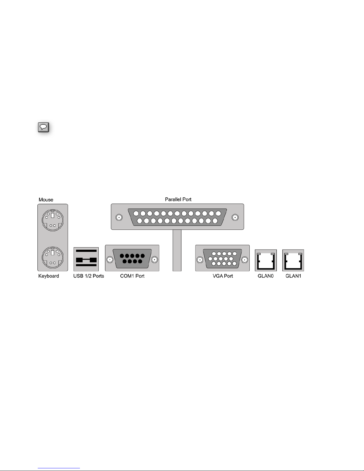
Initial Connections
For the initial installation of your bruAPP unit, plug your keyboard and monitor (mouse not required), at
least one network cable into GLAN0 (Ethernet port closest to the monitor port), and the power cord on
the back panel as outlined in Fig. 2.1 below.
Figure 4.1 – bruAPP Backup Appliance Rear I/O Panel
Note: Tower System arrangement is vertical, and some1U/2U/3U chassis will differ slightly.
Connecting a Tape Device
If you are attaching a SAS, SCSI or Fibre-Channel tape drive or library, connect it to the appropriate
ports.
3U Chassis SAS Tape Connection
bruAPP 3U Backup Appliances have two external SAS ports. One is labeled “Tape” (usually the top
port) and the other is labeled “Disk” (usually the bottom port) and when connecting the tape device to
your 3U bruAPP, you must plug the tape device into the “Tape” port only as shown if figure 4.2.
The “Disk” port is for planned future expansion of the bruAPP Backup Appliance for customers needing
to increase the total bruAPP RAID size.
12

Figure 4.2 ― The view of the 3U chassis SAS ports for disk and tape connections.
WARNING:
The “Disk” port is for future expansion and use of the bruAPP Backup Appliance from
TOLIS Group, is not to be used. Connecting a non-TOLIS Group disk to the “Disk”
SAS port of the bruAPP Backup Appliance will cause damage to the bruAPP/OS,
including the RAID array, and will result in return of the unit for Non-Warranty repair.
Non-Warranty does not cover to/from shipping and includes a hardware refurbishment
charge.
SCSI Tape Devices
For SCSI devices, you will need an LVD/SE VHDCI Male to SCSI-3 MD68 Male cable to connect the
SCSI tape device to the bruAPP Backup Appliance.
Fibre-Channel (FC) Tape Devices
For Fibre-Channel tape devices, you will need copper rather than optical cables. Otherwise, you will
need to supply appropriate GBICʼs to connect the optical cables to the mechanical/electrical connectors
in the provided FC HBA.
If you have purchased your bruAPP Backup Appliance with a TOLIS Group Library
(TGL1800, TGL2240, TGL4480, or TGL8960), the compatible SCSI, SAS, or FibreChannel cable will be included in the box with your tape library.
13
5 - Rack Installation
This section provides information on installing the 1U/3U bruAPP Backup Appliance into a server rack
unit with the rack rails provided. While the figures in this section show a 1U chassis, the concept for the
3U chassis is the same.
There are a variety of rack units on the market, which may mean the assembly procedure will differ
slightly. You should also refer to the installation instructions that came with the rack unit you are using.
Warning
The 3U bruAPP Backup Appliance is capable of holding 16 hard drives. When fully
loaded and the rail kit installed onto the 3U chassis, the net weight of the unit is
approximately 90 lbs (40.82 kg).
Therefore, install the bruAPP into the rack prior to inserting the hard drives to reduce the risk of injury.
Identifying the Sections of the Rack Rails
You may have received rack rail hardware in the same box as the 1U bruAPP Backup Appliance (two
front inner rails should already be attached to the chassis). This hardware consists of two rear inner
rails that secure to the chassis, one on each side just behind the pre-installed front inner rails. Note that
these two rails are left/right specific.
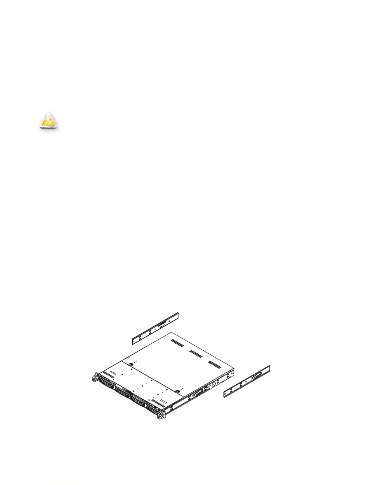
Installing the Rear Inner Rails
First, locate the right rear inner rail (the rail that will be used on the right side of the chassis when you
face the front of the chassis). Align the two square holes on the rail against the hooks on the right side
of the chassis. Securely attach the rail to the chassis with M4 flat head screws. Repeat these steps to
install the left rear inner rail to the left side of the chassis (see Figure 5.1). You will also need to attach
the rail brackets when installing into a telco rack.
Locking Tabs: Both chassis rails have a locking tab, which serves two functions. The first is to lock the
server into place when installed and pushed fully into the rack, which is its normal position. Secondly,
these tabs also lock the server in place when fully extended from the rack. This prevents the server
from coming completely out of the rack when you pull it out for servicing.
Figure 5.1 ― Installing the left and right rails on a 1U bruAPP Backup Appliance chassis.
14
Installing the Rack Rails
Determine where you want to place the 1U bruAPP in the rack (see Rack Mounting Considerations
below). Position the chassis rail guides at the desired location in the rack, keeping the sliding rail guide
facing the inside of the rack. Screw the assembly securely to the rack using the brackets provided.
Attach the other assembly to the other side of the rack, making sure that both are at the exact same
height and with the rail guides facing inward.
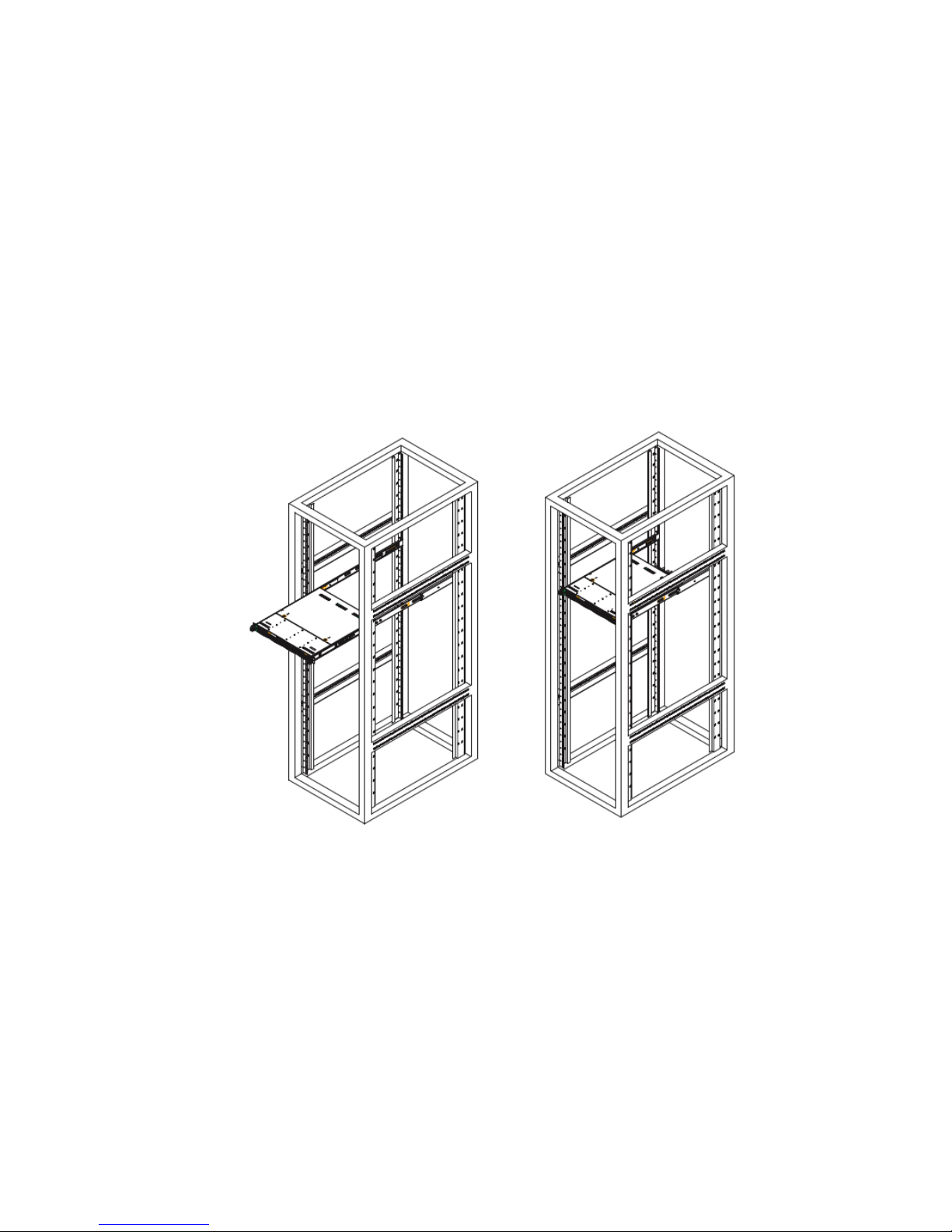
Installing the 1U/3U bruAPP into the Rack
You should now have rails attached to both the chassis and the rack unit. The next step is to install the
server into the rack. If the hard drives have been installed into the chassis, youʼll need to remove them
prior to attempting to lift the chassis into the rack (see the warning at the start of this chapter). Do this
by lining up the rear of the chassis rails with the front of the rack rails. Slide the chassis rails into the
rack rails, keeping the pressure even on both sides (you may have to depress the locking tabs when
inserting). See Figure 5.2.
When the server has been pushed completely into the rack, you should hear the locking tabs "click".
Installing the 1U bruAPP into a Telco Rack
To install the 1U bruAPP into a Telco type rack, use two L-shaped brackets on either side of the chassis
(four total). First, determine how far the server will extend out the front of the rack. Larger chassis
should be positioned to balance the weight between front and back. If a bezel is included on your
server, remove it. Then attach the two front brackets to each side of the chassis, then the two rear
brackets positioned with just enough space to accommodate the width of the rack. See Figure 5.3.
Finish by sliding the chassis into the rack and tightening the brackets to the rack.
Figure 5.2 ― Installing the rails into a server rack.
15
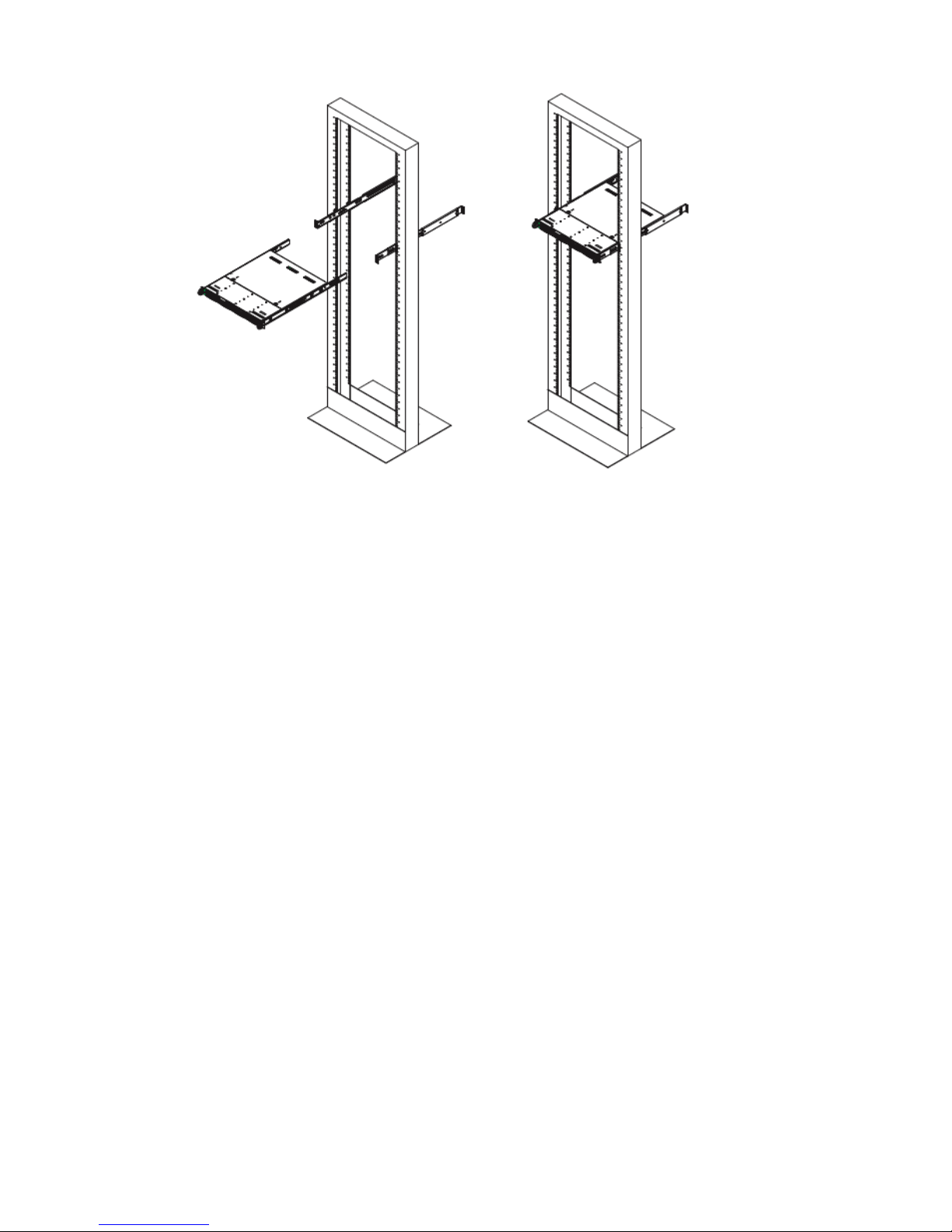
Figure 5.3 ― 1U bruAPP Telco Rack Installation
Installing the 3U bruAPP into a Telco Rack
While it is not recommended, if you must install the 3U bruAPP into a telco rack, the unit must be
installed on a shelf to fully support the weight of the unit. The enclosed rails that ship with the 3U
chassis cannot be used to install the unit into a telco rack.
Rack Mounting Considerations
Rack Precautions
Ensure that the leveling jacks on the bottom of the rack are fully extended to the floor with the full
•
weight of the rack resting on them.
In single rack installation, stabilizers should be attached to the rack. In multiple rack installations,
•
the racks should be coupled together.
Always make sure the rack is stable before extending a component from the rack.
•
You should extend only one component at a time - extending two or more simultaneously may
•
cause the rack to become unstable.
Server Precautions
Determine the placement of each component in the rack before you install the rails.
•
Install the heaviest server components on the bottom of the rack first, and then work up.
•
Use a regulating uninterruptible power supply (UPS) to protect the server from power surges,
•
voltage spikes and to keep your system operating in case of a power failure.
Allow the hot plug SATA drives and power supply modules to cool before touching them.
•
Always keep the rack's front door and all panels and components on the servers closed when not
•
servicing to maintain proper cooling.
Ambient Operating Temperature
If installed in a closed or multi-unit rack assembly, the ambient operating temperature of the rack
environment may be greater than the ambient temperature of the room.
16

Therefore, consideration should be given to installing the equipment in an environment compatible with
the manufacturerʼs maximum rated ambient temperature (Tmra).
Reduced Airflow
Equipment should be mounted into a rack so that the amount of airflow required for safe operation is
not compromised.
Mechanical Loading
Equipment should be mounted into a rack so that a hazardous condition does not arise due to uneven
mechanical loading.
Circuit Overloading
Consideration should be given to the connection of the equipment to the power supply circuitry and the
effect that any possible overloading of circuits might have on overcurrent protection and power supply
wiring. Appropriate consideration of equipment nameplate ratings should be used when addressing this
concern.
Reliable Ground
A reliable ground must be maintained at all times. To ensure this, the rack itself should be grounded.
Particular attention should be given to power supply connections other than the direct connections to
the branch circuit (i.e. the use of power strips, etc.).
17
6 - Powering On Your bruAPP
Depending on the bruAPP Backup Appliance that you ordered, the power button my be behind a
faceplate, on the back of the unit, or may require a small pen or screwdriver to power on. Please use
the appropriate section below for your bruAPP model.
Turn the unit on using a small tool such as a pen or small star screwdriver (do NOT use a pencil as lead
particles could interfere with the switch operation over time).
Tower Systems
For tower systems, turn the unit on using the front panel power switch. If the unit does not turn on,
check the switch on the power supply on the back of the unit and make sure that it is switched to the on
position.
1U Rackmount Systems
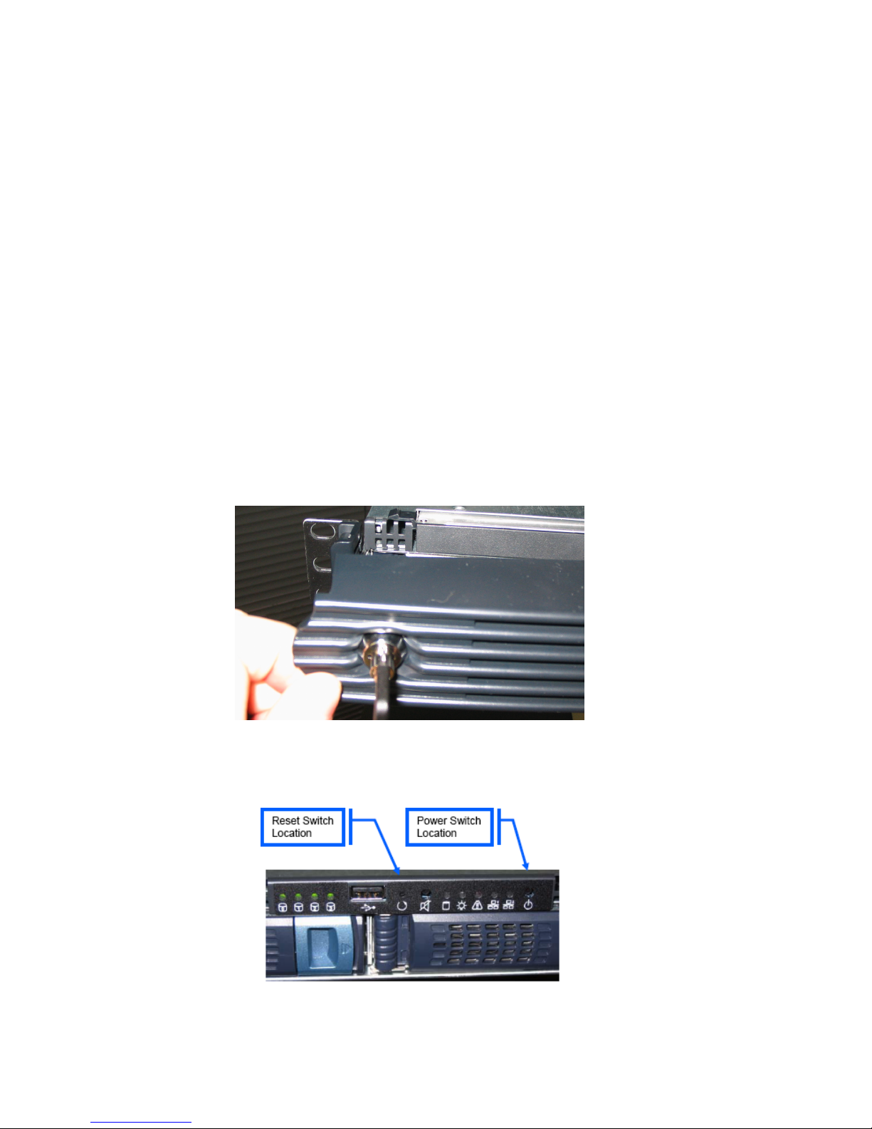
For 1U rackmount systems that have a faceplate/bezel, unlock the faceplate/bezel and remove by
grasping the left end and swinging it outward from left to right. See figure 6.1. As chassis designs may
vary between bruAPP models from the 1U unit described and shown below, your faceplate/bezel
removal process may differ slightly.
Fig. 6.1 ― Removal of the 1U chassis faceplate/bezel.
Once the faceplate/bezel has been removed, locate the Power and Reset switches. See figure 6.2.
Power the bruAPP on by pressing the Power switch.
Figure 6.2 ― Location of power and reset switches.
18

3U Rackmount Systems
3U rackmount systems do not have a faceplates/bezel. The power button is located on either the rear
of the unit or on the front of the unit in the bottom-left (see figure 6.3) or bottom-right corner with the
LED indicator lights below the power button.
Figure 6.3 ― Front view for the bruAPP 3U chassis. Power button and LEDs are on the
lower left side of the chassis, just under the rack handle.
All 3U systems utilize a hard drive carrier that inserts vertically instead of horizontally. The drives for 3U
bruAPPʼs will also ship separately due to weight limitations of packing and to ensure the hard drives are
not damaged during shipment. Make sure you insert all hard drives into the bruAPP before you power
on a 3U bruAPP for the first time.
19

7 - Initial Configuration
After the initial power-on, you will be prompted with the bruAPP/OS Welcome screen (figure 7.1). The
following will walk you through each of the setup screens to fully setup your bruAPP Backup Appliance
and configure it for use.
Figure 7.1 ― bruAPP/OS Welcome Screen
From this point on, use the keyboard to navigate all of the bruAPP/OS screens. Use of the mouse is
not supported and therefore mouse movements are ignored. Keystrokes are:
" [TAB] key to move between setting options, the action buttons.
" [ARROW KEYS] to highlight a desired option.
" [SPACEBAR] to select your desired option.
" [ENTER] will save the current settings and continue to the next option screen.
For future reference of all settings that you set, we suggest that you write the settings
down in the “Saved Settings” section of this manual in the event that you need to
reapply the settings to the values that you set originally.
Network Setup
The first part of the bruAPP/OS setup is to configure the bruAPP network settings. There are two
Ethernet ports on the bruAPP. You may configure them to connect to two different networks (using
subnets) or you may only connect one. If you use only one Ethernet port, make sure you plug in the
Ethernet cable to the ETH0 port (closest to the VGA port).
It is strongly discouraged to connect both Ethernet ports to the same network unless you properly
configure your network environment. Using both NICs on the same network may cause problems with
backup operations.
Configure Ethernet Port 0
The first part of the network setup will be for the ETH0 port. To ensure consistent communication to the
bruAPP, it strongly advised to use static IP addresses for the bruAPP and any client machine you will be
having the bruAPP backup. It is not required, but it will greatly reduce connectivity problems because of
IP addresses changing in installations where DHCP is used for servers.
20
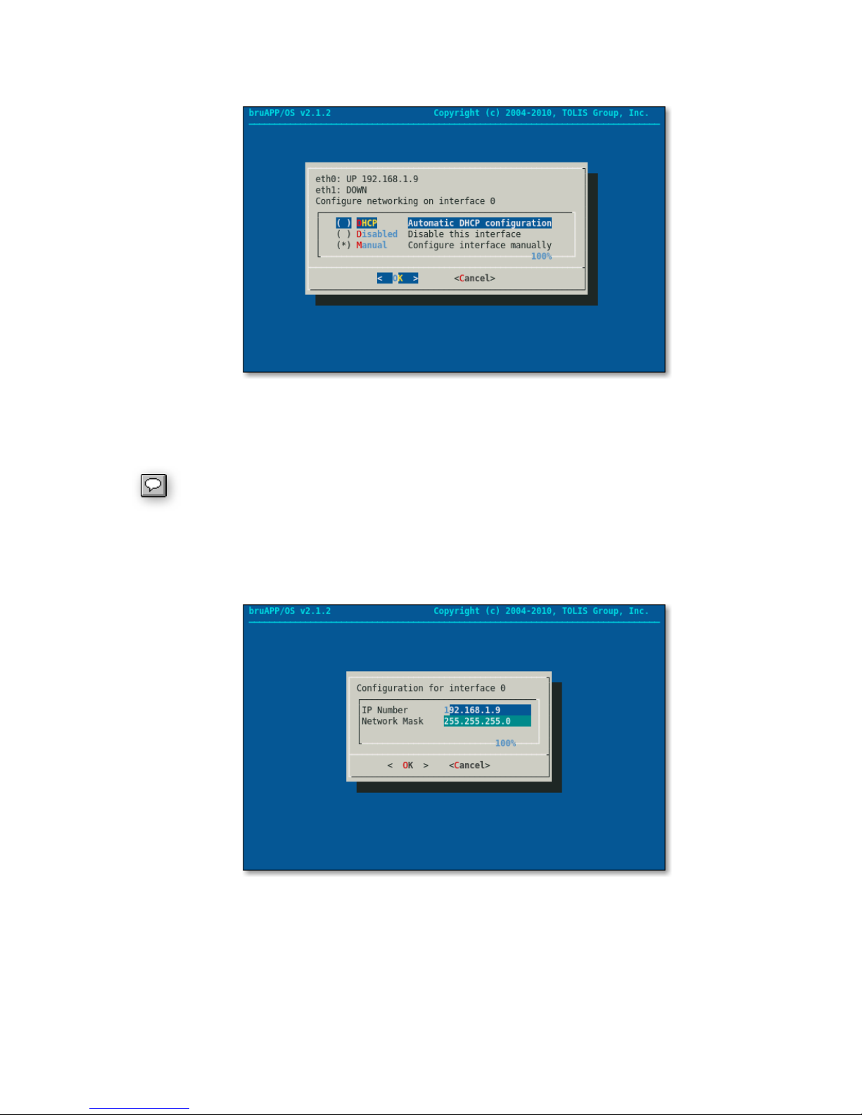
Using the arrow keys, highlight the option you want to have ETH0 be set to. Either manually set (static
IP) or if the ETH0 port will use DHCP. See figure 7.2.
Figure 7.2 ― Network Setup for ETH0.
Once you have highlighted “DHCP” or “Manual” for ETH0, press the [SPACEBAR] to select that option.
Once the option is selected, press [ENTER] to move to the next screen.
If you selected “DHCP” then you will be moved to the ETH1 port configuration screen.
If you selected “Manual”, enter the IP address and network (subnet) mask that the ETH0 port will be
using. Press [TAB] or use the arrow up/down keys to move between fields. See figure 7.3. Once
you've entered the desired values, press [ENTER] to continue to the next screen.
Figure 7.3 ― IP and Network Mask (Subnet Mask) settings for ETH0.
Once you have configured the IP address and network mask it is now time to configure the bruAPP's
hostname, gateway server and DNS servers. See figure 7.4.
Make sure that the hostname you enter is a unique name and is in a Fully Qualified Domain Name
(FQDN) format (i.e. bruapp.domain.com). Entering just the hostname may cause network errors.
21

Figure 7.4 ― Hostname, Gateway, and DNS server configuration.
Once you have finished with the Host Configuration of ETH0, you will be moved to the configuration of
ETH1.
Configure Ethernet Port 1
Most bruAPP users will not configure the bruAPP to use ETH1 since most connect the bruAPP to a
single network. If that is the case, then choose the “Disabled” option for ETH1 and press [ENTER] to
move to the next screen.
If you are connecting the bruAPP to two different networks, then perform the setup for ETH1 in the
same manner that you did for ETH0 using the second network values you want to be used.
Apply Network Settings
Once you have configured the settings for both Ethernet ports, the bruAPP/OS will now apply the
settings, creating the appropriate files for proper network connectivity.
If DHCP is used, the IP addresses for ETH0 and ETH1 can be logged in the “Saved Settings” section of
this manual.
Setting the Date & Time
The configuration of the bruAPP system date and time is first done manually, then you'll be prompted to
configure the NTP settings.
Set the Date
Setting the date on the bruAPP/OS consists of selecting the Month, Year and the Day, in that order.
Use the [TAB] and arrow keys to switch between fields and the change values within each field. Your
date screen should look like figure 7.5.
22

Figure 7.5 ― Manually set the Month, Year and the Day for the bruAPP/OS.
Setting the Time
Manually Set the Time
The Time screen allows you to set the current time of the bruAPP manually. This is helpful for
installations where there is not an in-house system that serves as a Network Time Protocol (NTP)
server or access to the internet on port 123, the NTP port, is restricted.
When you have completed the time and date, the bruAPP will set the system date and time based on
the values you provided. A dialog will appear to report what the current system time has been set to.
See figure 7.9.
Automatically Set the Time
The bruAPP/OS has the ability to set the system date and time using either an in-house NTP server or
an internet NTP server. By default, the bruAPP/OS NTP service is configured to connect to public NTP
servers (0.pool.ntp.org). If, however, you want to use an in-house machine or a different NTP server,
the NTP set will allow you to do so.
First, select your timezone from the list of available timezones. See figure 7.7.
Figure 7.6 ― Manually set the system time.
23

Figure 7.7 ― Set the system's timezone.
To speed the process of going through the timezone list, which is in alphabetical order by region, use
the [PAGE UP] and [PAGE DOWN] keys. Once you see your timezone in the list, use the arrow keys to
move one-by-one to the desired timezone. Press [ENTER] to select the timezone and move to the
NTP server configuration.
On the NTP server screen, figure 7.8, you my either leave the field set to “default” or you may enter
your desired NTP server. If you choose to use the “default” option, the server 0.pool.ntp.org will be
used to set the system date and time. For a complete list of time servers worldwide, visit www.ntp.org.
Figure 7.8 ― NTP Server configuration.
You may either enter the FQDN of the time server or the IP address. Either are acceptable, however,
please be aware that a valid DNS server entry is required on the bruAPP in order to resolve the FQDN
to an IP address.
Applying the System Date & Time ― NTP
Once you have configured both the manual and NTP settings, the bruAPP will now set the system time
and display what the current system time has been set to (figure 7.9).
24

Figure 7.9 ― Report of the current system time.
Setting the RAID Administrator
The bruAPP Backup Appliance requires a RAID administrator email address so that in the event that
there's a RAID status update an email will be sent to the email address provided. See figure 7.10.
Figure 7.10 ― RAID administrator email setup.
After the RAID administrator email has been entered, press [ENTER] to move to the next screen. A test
email will be sent to the email address using the existing Mail eXchange (MX) record for the domain
used.
RAID Administrator SMTP Configuration
This feature is currently being added to the bruAPP/OS. There is no current mechanism to allow
SMTP authentication at this time.
Setting the bruAPP Admin Password
The bruAPP admin password is the same password as the 'admin' user for the BRU Server software.
Changing the 'admin' password on the bruAPP will also change the 'admin' user password when
logging into the BRU Server Console.
25
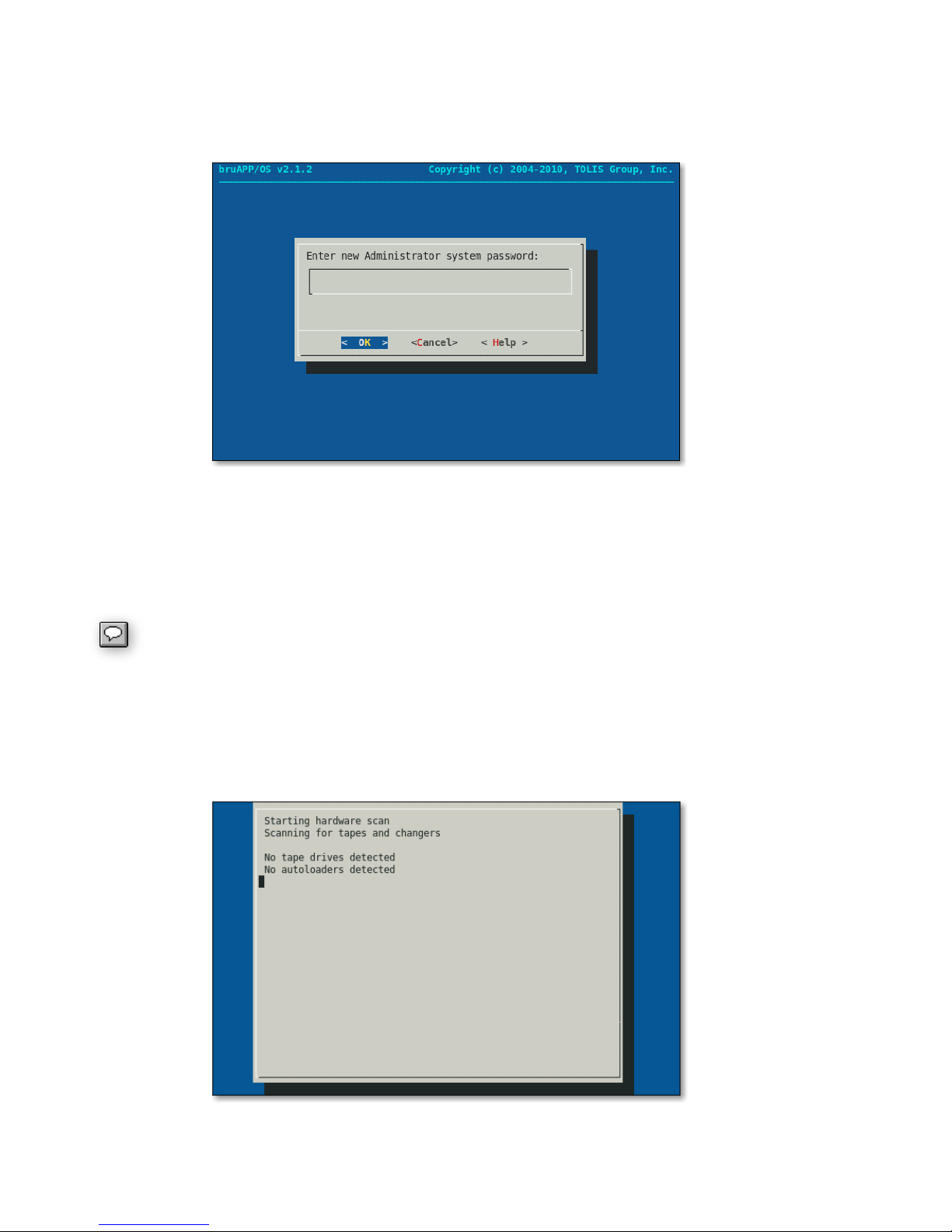
Using the same keystrokes in other screens, enter the password you want to use for the 'admin' user of
both BRU Server and direct access to the bruAPP. For security purposes, when you type the password
into the Administrator password screen (figure 7.11), nothing will appear as you type, continue to enter
your password and press [ENTER].
Figure 7.11 ― Administrator password screen.
The next screen will appear just like the original Administrator password screen, this is a confirmation
screen to ensure that you typed the password correctly the first time. If the first and second password
entered do not match the process will need to be started over to enure that the password that gets set
is intentional.
Password Security: The bruAPP will accept both simple and complex passwords of
any length. It is up to you to create a password that adheres to your organization's
security policies. It is recommended to keep the password between eight (8) and 16
characters in length.
Performing the Initial Hardware Scan
Now that your bruAPP has been configured, the BRU Server software must now perform a hardware
scan to detect any tape devices connected to the bruAPP for D2T or D2D2T operations. See figure
7.12.
Figure 7.12 ― BRU Server Hardware Scan.
26
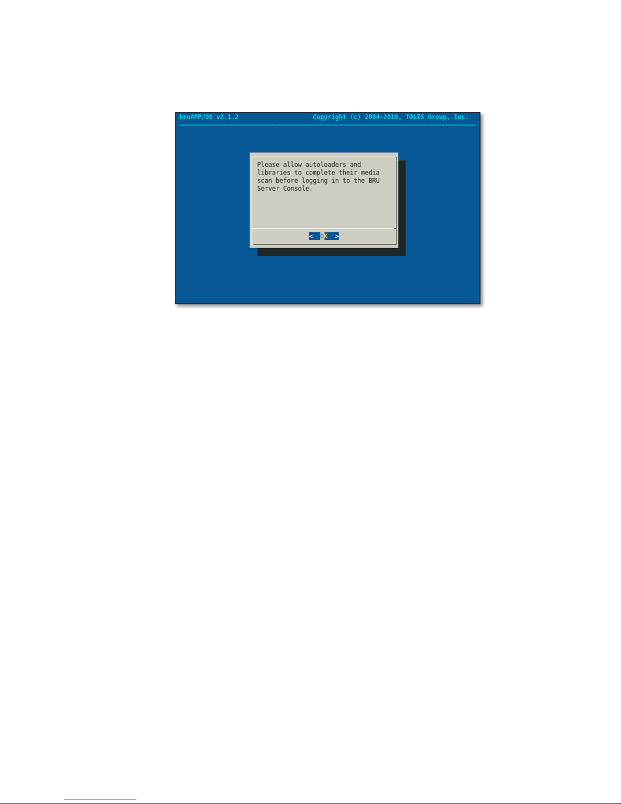
Final Step: Reboot
When the hardware scan has completed you will see a dialog indicating that the hardware scan has
completed (figure 7.13). At this point, the bruAPP will now reboot to set all system settings, match the
system time with the hardware time, and perform other various final operations.
Figure 7.13 ― BRU Server Hardware Scan completed dialog.
When the bruAPP has completed the reboot process, your bruAPP Backup appliance is now ready to
use!
Setup BRU Server Agents
At this point, it is now time to setup your BRU Server Agents and BRU Server Console. Please refer to
the BRU Server Admin Guide for information on installation and configuration of Agent and Console
installations based on the operating system you will be using.
27

8 - Additional Options
The bruAPP/OS has other additional options and features that you can utilize if you choose to do so,
but they are optional items and provided as an additional service or tool to aid in overall functionality of
the BRU Server software running on the bruAPP Backup Appliance.
For example, the bruAPP/OS is equipped with a Network Time Protocol (NTP) daemon that ensures
synchronization of the bruAPP/OS software and hardware clocks with official time servers and the goal
of the NTP service on the bruAPP is to ensure that all BRU Server schedules run on-time. The
bruAPP/OS does not provide the ability to be a NTP server.
Due to changes in the bruAPP/OS, the menu options below may not appear in the order
they are displayed on the bruAPP/OS menu.
bruAPP/OS Main Menu
From the bruAPP/OS Main Menu, you have several options. For information on a specific menu option,
see the categories below.
In addition to the System Configuration and BRU Server menus, you also have the ability to view the
TOLIS Group Technical Support contact information, reboot the bruAPP, power off the bruAPP, or logout
of the bruAPP.
Support Information
In case you need to contact TOLIS Group support and you donʼt have your Rolodex handy, you can
select this option to view the current TOLIS Group contact information.
System Reboot
If you have changed the system timezone, performing a bruAPP/OS update or decide you need to
reboot for any other reason, choosing this menu option will tell the bruAPP/OS to reboot the system.
System Poweroff
If youʼre changing hard disks due to a power failure, moving the bruAPP, or any other reason that you
need to power off the bruAPP Backup Appliance, selecting this option from the main menu will tell the
bruAPP/OS to power down.
When performing a system reboot or power off, the bruAPP appliance will do it
immediately. Any currently running backups in progress by BRU Server will be
terminated and they cannot be resumed from where the job was killed. If you do not
want to terminate the running backups, you must wait until the backups have completed
before performing a reboot or power down.
BRU Server Main Menu
From the bruAPP/OS Main Menu, use the arrow keys to highlight “BRU Server” and press [ENTER] to
move to the BRU Server Main Menu.
bruAPP Stage Status
You can view the stage status of the bruAPP to determine the current amount of available space and
the amount of used space.
28
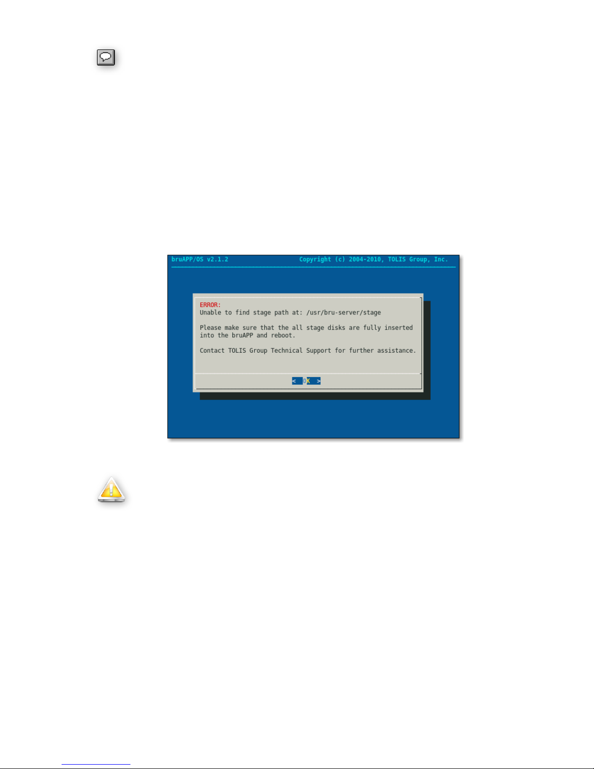
This is only available on bruAPP Backup Appliances that have an internal RAID array.
For bruAPP's that do not have a built-in RAID, and error message like the one in figure
8.1 will be displayed.
To get the bruAPP stage status, perform the following steps:
1. Login to the bruAPP/OS.
2. From the bruAPP/OS Main Menu, use the arrow keys to highlight “BRU Server” and press
[ENTER].
3. From the BRU Server Main Menu, using the arrow keys again, highlight “Stage Status” and
press [ENTER].
4. The bruAPP stage status window will appear.
If the stage status cannot be displayed, either because the RAID did not mount properly at boot or
because your particular bruAPP model does not have an internal RAID, an error will be displayed like
the one in figure 8.1.
Figure 8.1 ― Stage status error when the stage disk is not available.
bruAPP Stage Path
The stage path for BRU Server on the bruAPP is /usr/bru-server/stage. It should never
be changed from that path. Changing the BRU Server stage path on the bruAPP to
anything other than /usr/bru-server/stage will cause the stage backups to fail as that is
the mount point for the bruAPP RAID.
For bruAPPʼs that do not have an internal RAID array, the BRU Server stage path must
still be /usr/bru-server/stage to allow the unit to accept a RAID if hard drives are ever
added in the future.
BRU Server Text Console
The bruAPP/OS has the BRU Server Text Console available for direct BRU Server access. To access
the Server Text Console, press ALT-F2 (press and hold the ALT key then press the F2 key while holding
the ALT key).
You'll be presented with the BRU Server Text Console. To get started, press [ENTER] and then login
using the same username/password combination that you would normally use in the BRU Server
Graphical Console from a remote system.
29
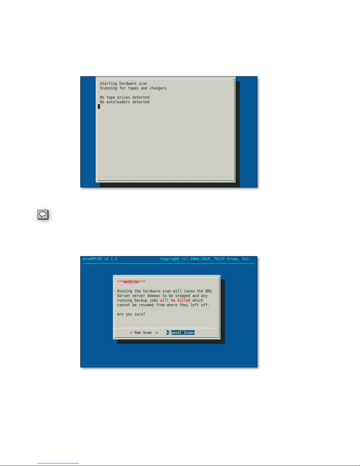
BRU Server Hardware Scan
In the event that you need to run a hardware scan on the bruAPP, use the “Hardware Scan” option to
re-scan for tape devices, new or old, that have been connected to the bruAPP Backup Appliance.
You'll see the progress of the hardware scan (figure 8.2) while it runs.
Figure 8.2 ― BRU Server Hardware Scan status.
When connecting new tape devices to the bruAPP, a reboot of the bruAPP system is
required in order for the bruAPP/OS to properly see and use the device in BRU Server.
When running a hardware scan, any backup or restore operations will be terminated. A warning is
displayed (figure 8.3) to alert of this when the hardware scan is selected.
Figure 8.3 ― BRU Server Hardware Scan warning.
If there are running operations in BRU Server when the hardware scan is performed they cannot be
resumed from the point at which they were terminated. All operations must be started from the
beginning.
30
BRU Server Agent Configuration
The bruAPP Backup Appliance ships with the BRU Server Agent software pre-installed and ready to be
configured. If you want to backup the bruAPP system, including the BRU Server Environment, the
Agent must be configured before you can run backups, just like any other BRU Server Agent system.
When you authenticate the BRU Server Agent to the BRU Server Server (the bruAPP itself), it will
occupy a client license “seat”. Therefore, if your bruAPP ships with 25 clients, after authenticating the
BRU Server Agent to the BRU Server Server you will have 24 remaining clients available for backup.
Tip: When you authenticate the BRU Server Agent running on the bruAPP to the BRU Server Server
running on the bruAPP, it is suggested that you use the name “localhost” when prompted for the name
of the BRU Server system.
Alternatively, you can use the IP address of 127.0.0.1.
BRU Server Daemon Restart
In the event that the BRU Server Server daemon needs to be restarted on the bruAPP, under the BRU
Server Main Menu the “Restart” option will perform a BRU Server Server daemon restart.
Warning
When restarting the BRU Server Server daemon, any backup or restore operations
that are running will be terminated. Once terminated, the backup/restore operation
cannot resume from where it left off. The backup/restore operation must be started
over from the beginning.
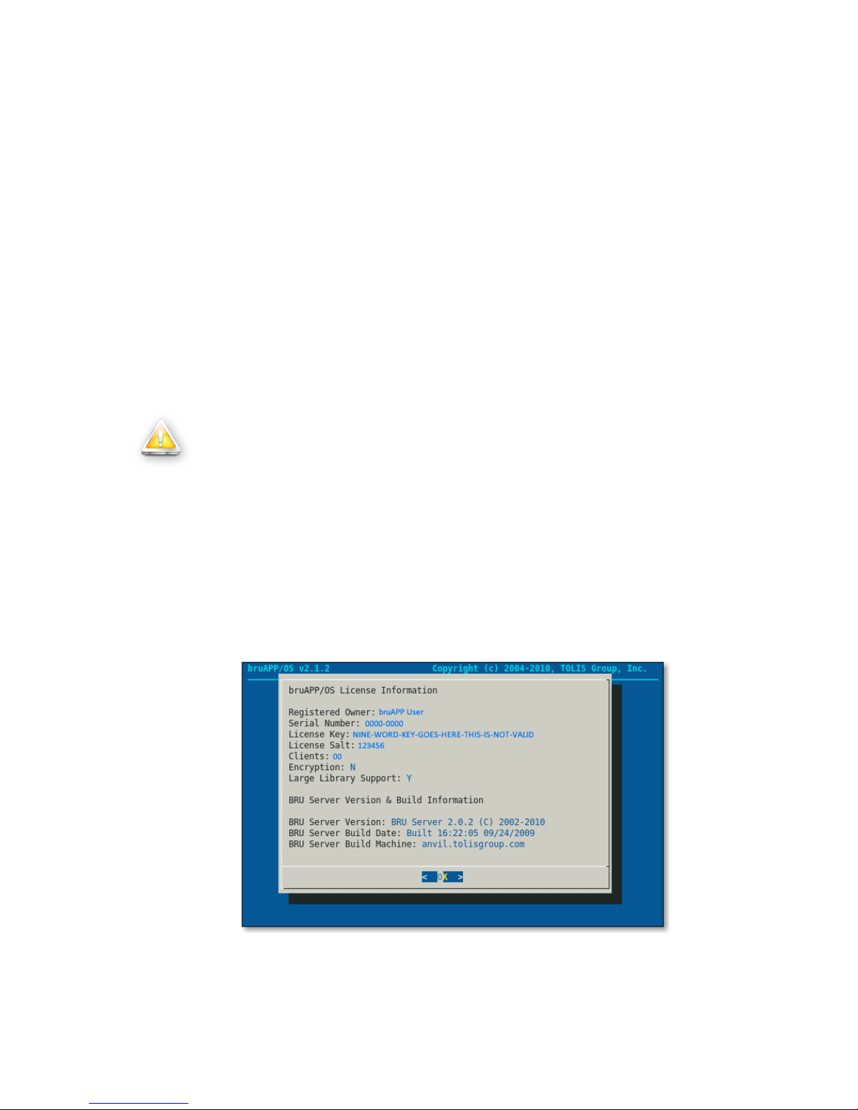
BRU Server License & Version Information
For support and informational purposes, the “View Details” option of the BRU Server Main Menu will
display the currently set BRU Server License information and the current BRU Server version & build
information. See figure 8.4.
This information may be requested by TOLIS Group Technical Support in the event that you need
technical assistance with your bruAPP.
Figure 8.4 ― BRU Server License and Version information. This above example
does not contain valid license information.
31

Update License Information
When you purchase additional clients for BRU Server, add large library support, or add the BRU Server
Encryption module you will get a new license from BRU Sales. When you get this new information you
may enter the license information, overwriting the old license (since it's no longer a valid/legal license)
information by using the “License” option.
Figure 8.5 shows the BRU Server license screen. When you enter this new license, you must enter the
information in the exact same way that is has been provided to you. This means that if the Registered
Owner field is misspelled, you need to contact BRU Sales to have the license corrected and a new
license provided to you with the correct spelling.
Figure 8.5 ― BRU Server license screen.
This also applies if the company name has a hyphen, space, ampersand, or other special character in
the name. All of the information must be entered EXACTLY as is has been give to you. The names
“TOLIS Group, Inc.” and “Tolis Group, Inc.” are not the same.
In figure 8.3 it shows an example license. In the example license the Registered Owner field is
“bruAPP User”. When entering this, it will not be accepted as “BruApp User”, “bruapp user”, or even
“bruAPP user”. It must be entered as “bruAPP User” since that's the name the license was created
from and therefore will not be valid as anything but “bruAPP User”.
Change Password
In the event that you want to change the bruAPP/BRU Server ʻadminʼ user password, select this option.
You will be asked to enter the new password, followed by a password confirmation screen. Once the
password has been applied, the system will reboot to ensure any logged in users of the BRU Server
Console are automatically logged out.
System Configuration Menu
The bruAPP/OS System Configuration Menu has the options and tools for the bruAPP/OS itself. The
changes made here not only affect the BRU Server software running on the bruAPP, but they may
affect the overall functionality of the bruAPP Backup Appliance itself.
The System Configuration Menu, figure 8.6, shows the options that are available for bruAPP users.
32

Figure 8.6 ― bruAPP/OS System Configuration Menu.
bruAPP/OS Update Check
This option performs a check of the bruAPP/OS against the latest available version listed on the TOLIS
Group website. An internet connection to the TOLIS Group servers (via port 80) is required in order for
this option to work.
If your bruAPP/OS version is up-to-date, you'll see the message displayed in figure 8.7. If an update is
available for the bruAPP/OS, you'll see an “Update Available” message.
In the event that there's an update that has become available for your bruAPP/OS, you can download
the updated version, as well as any instructions on installing the update, from the TOLIS Group website
at: http://www.tolisgroup.com.
In an effort to prevent problems during the update process the bruAPP/OS cannot be
updated via the internet or while the system is running. The bruAPP must boot from
update media in order to ensure a proper update process. At each bruAPP/OS release
an upgrade guide is published to walk users through the overall update process. This
guide can be obtained from the TOLIS Group website at http://www.tolisgroup.com/
Figure 8.7 ― Successful bruAPP/OS Update Check.
33
bruAPP/OS Network Settings
In the event that there are network changes that need to be made, the “Network” option of the System
Configuration Menu will enable you to make any changes to any of the following network options:
IP address for ETH0 and ETH1
•
Subnet Mask for ETH0 and ETH1
•
DNS 1, DNS 2, or DNS 3 servers
•
Gateway IP address
•
bruAPP system hostname
•
Changing any of these options will affect any network operations that are currently running, such as
backup/restore operations or users using the bruAPP Web Interface.
bruAPP/OS Network Configuration
From the System Network Configuration menu, use the “Configure” option the make changes to the
Ethernet settings, DNS, hostname, Gateway IP, and Subnet Mask.
bruAPP/OS Network Test
To assist in troubleshooting network issues on the bruAPP Backup Appliance, there are two tests that
get performed for network configuration testing.
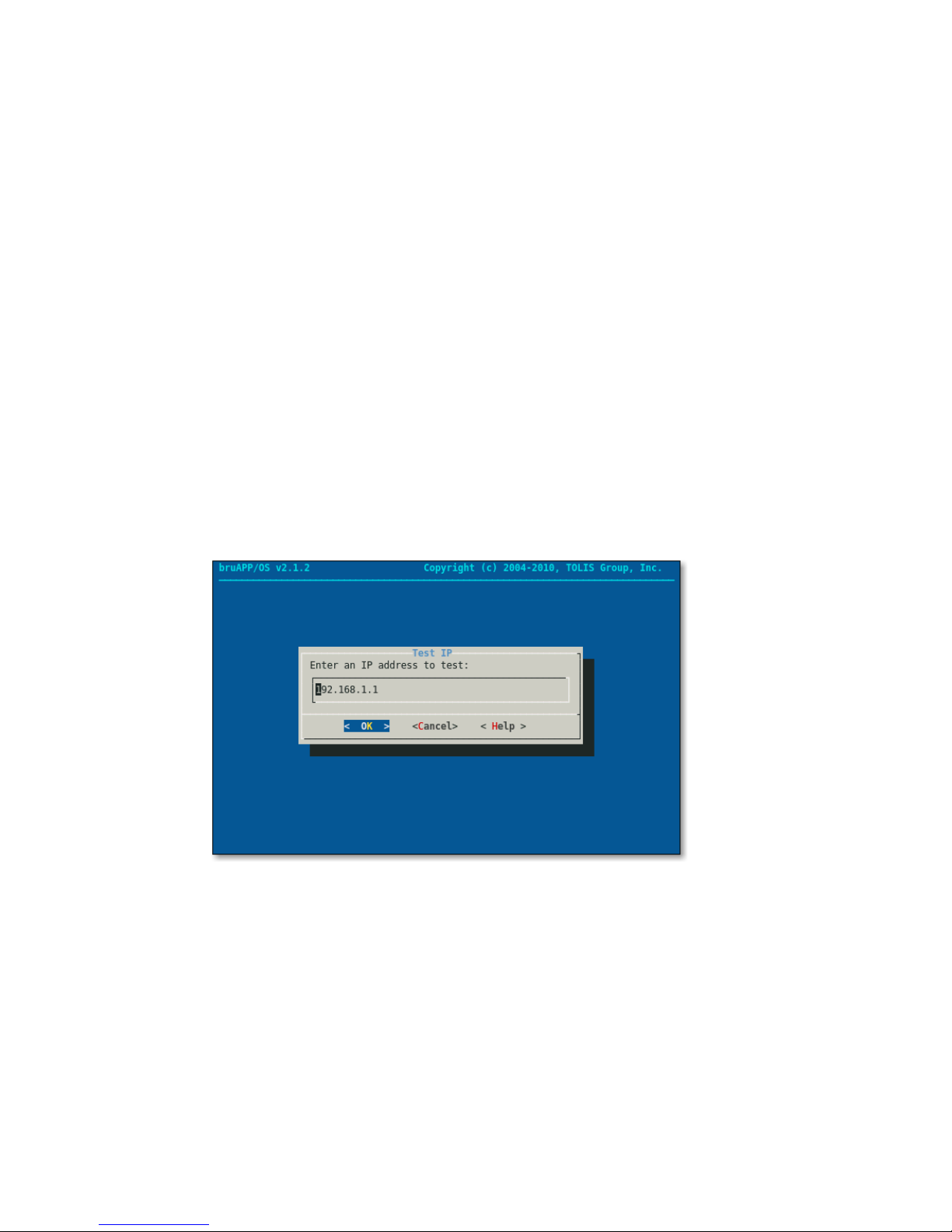
The first is an IP ping test. To conduct a general connectivity test, on the first screen (figure 8.8) enter
the IP address of a system that is known to be connected to the network and working as expected. The
IP address can also be an internet IP address to test internet connectivity from the bruAPP.
Figure 8.8 ― Network Connectivity test using 'ping' to ping an IP address.
Once an IP address has been entered, select OK to conduct the test. Four ping attempts will be
performed from the bruAPP to the IP address provided. See figure 8.9.
34

Figure 8.9 ― Network Connectivity test active for an IP address.
The next test that can be performed from the bruAPP is a DNS test to test the overall DNS capabilities
from the bruAPP. This is important for a number of reasons. The BRU Server software has its own
built-in Mail Transfer Agent (MTA) and in order to email to a given email address, the BRU Server
software performs an Mail eXchange (MX) record lookup for the given domain the email address. This
MX lookup requires both internet access and proper DNS resolution.
Another purpose for DNS is to ensure that the BRU Server software can find the client machines that
need to be backed up when BRU Server asks for the machine by name.
A number of other important factors apply with DNS and the bruAPP Network DNS test helps to debug
many of those errors.
Figure 8.10 ― Network DNS (FQDN) test for DNS resolution.
Figure 8.10 shows the DNS test prompt. In the field provided, you may enter any Fully Qualified
Domain Name (FQDN) into this field provided that it's a valid FQDN that exists on either the Internet or
local network.
To test Internet DNS, enter an outside server such as “www.tolisgroup.com” or your companies website.
For an in-house system, enter the FQDN for the in-house system. After the address has been entered,
select OK or press [ENTER] to conduct the test as shown in figure 8.11.
35

Once the test has completed, if there were errors, make any changes or adjustments to your IP, DNS,
Gateway, or Subnet Mask as needed to ensure proper connectivity. Otherwise, upon successful
completion, the network tests are done.
Figure 8.11 ― Network DNS test being performed on the bruAPP.
bruAPP RAID Configuration
The bruAPP RAID Configuration menu allows you to set the RAID Administrator email address, the
person notified by the bruAPP for all RAID notifications (online, offline, disk failures, etc), and the ability
to manually rebuild the bruAPP RAID array to the default RAID level as requested when the bruAPP
was ordered.
Customers who ordered the bruAPP with RAID 5 and a hot spare, the unit will rebuild the RAID using
level 5 with a hot spare. The same applies for RAID 0 (“stripe”), RAID 5, RAID 6, and RAID 6 with hot
spare.
At this time, is it not possible to specify the RAID level that is used on the bruAPP by using the “Rebuild
RAID” option.
RAID Administration
The RAID Administrator option allows for a single email address to be used for bruAPP RAID
notifications sent out by the bruAPP/OS.
In addition to the RAID Administrator email address, notifications are displayed on the bruAPP Web
Page in the event of a RAID alert. You can visit the bruAPP Web Page by typing in the hostname or IP
address of the bruAPP Backup Appliance into your favorite browserʼs address bar. If there is an alert, it
will be displayed at the top of the page in a color-coded alert box.
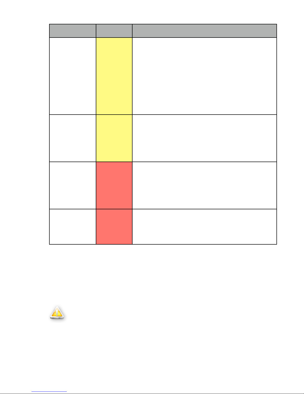
RAID Notifications, priority levels, and descriptions can be found in figure 8.12.
36

Notification
Priority
Description
TestMessage
Test
This is a test message since the 'test' command was given as
RAID startup. This message will also be generated in the
event that the RAID Admin email address was changed to test
the new email address given.
This email can be deleted and the rest of this message can be
ignored.
MoveSpare
Informational
A spare drive has been moved from one array in the sparegroup to another to allow a failed drive to be replaced.
No further action is required by you at this time.
NewArray
Informational
A new RAID device has been detected in on the bruAPP
Backup Appliance.
No action is needed from you at this time.
RebuildStarted
Informational
The RAID array has begun the process of rebuilding. This
can occur when a component of the RAID fails and the spare
is started or when a failed component has been replaced and
the spare is being returned to 'spare' status.
No further action is required by you at this time.
Rebuild
Informational
The RAID has completed __ percent of the rebuild process.
Updates are periodically given at regular intervals. A final
message will be sent when the rebuild process is completed.
No further action is required on your part at this time.
RebuildFinished
Informational
The RAID array that was rebuilding is no longer rebuilding.
Either because the rebuild completed successfully or because
it was aborted.
If the rebuild was aborted, an additional notification message
will be sent following this message.
No action is needed from you at this time.
SpareActive
Informational
A spare component device, which was being rebuilt to replace
a faulty device, has been successfully rebuilt and has become
active.
No further action is required by you at this time.
Degraded
Warning
The RAID array appears to be degraded.
At this time you should take appropriate actions to repair the
disk in the RAID array that has caused the RAID to run in
degraded mode.
37

Notification
Priority
Description
Fail
High
An active component in the RAID array has been marked as
faulty. The RAID spare, if available, will now be used.
An additional alert will be sent indicating the next step.
FailSpare
High
A spare component device which was being rebuilt to replace
a faulty device has failed. If another spare is available, it will
be used. If no other spare devices are available then the
RAID will run in degraded mode until both the spare and failed
device are replaced.
Perform appropriate actions to replace the failed spare disk.
DeviceDisappeared
High
The RAID array which was previously configured appears to
no longer be configured. The RAID is not defined and is
therefore no longer running.
Check the RAID array, make sure that all disks are securely
inserted into the bruAPP Backup Appliance and reboot the
bruAPP.
Figure 8.12 — bruAPP RAID Alert message descriptions.
Notification
Priority
Description
System Reboot
Informational
The bruAPP Backup Appliance has had a system configuration
change that requires a system reboot in order for the change to
become fully effective.
Please reboot the bruAPP Backup Appliance as soon as
possible to allow all changes to be properly made.
Server Restart
Informational
The BRU Server Server daemon has had a configuration
change that requires the daemon to be restarted in order for
the change to become effective.
This type of change is any type of change to the BRU Server
software itself, such as a license file change.
Please restart the BRU Server server daemon on the bruAPP
as soon as possible.
Colors in the priority field are the same colors used on the alert box displayed on the web interface.
In addition to these alerts, the web interface will display alerts that may occur during boot. The possible
messages are shown in figure 8.13.
Web alerts will include a timestamp to inform you of when the alert was made.
38
Notification
Priority
Description
DiskMissing
Warning
The bruAPP RAID has reported disk __ as missing from the
RAID array. The RAID is therefore offline and all D2D backups
are disabled.
The bruAPP has detected that there is a tape device attached,
please go to the bruAPP, acknowledge this warning by
pressing [ENTER] to enable backup operations to the attached
tape device. Once done, please contact TOLIS Group
Technical Support for further assistance.
The bruAPP will not finish itʼs boot sequence until an
administrator has acknowledged this warning.
Ta pe O nl y
Warning
The bruAPP has been set to Tape Only Mode because disk __
is missing from the bruAPP RAID array. A tape device has
been found to be connected to the bruAPP system and an
administrator has acknowledged the missing bruAPP disk.
Please contact TOLIS Group Technical Support for further
assistance.
MissingD2T
High
The bruAPP RAID has reported disk __ as missing from the
RAID array. The bruAPP has also detected that there are no
tape devices attached and therefore all backups, Disk-to-Disk
and Disk-to-Tape, have been disabled. The unit is now offline.
At this point, the bruAPP Backup Appliance cannot perform
backup operations due to missing hardware and is halted.
RAIDFailure
High
The bruAPP RAID has detected a failure and needs immediate
attention.
This message will also cause an email to be sent to the
bruAPP RAID Administrator.
Figure 8.13 — bruAPP web alerts and descriptions.
Rebuild RAID
The bruAPP/OS allows the ability to completely rebuild the RAID array in the even that there have been
too many disks fail or if there is any other reason in which the whole RAID needs to be completely
erased and rebuilt from scratch.
Warning
The “Rebuild RAID” option will completely erase all RAID hard drives, including any
data that resides on them, in order to properly rebuild the RAID array. If you have
staged archives on the bruAPP RAID array, it is strongly advised that you perform an
UpStage operation to move the archives from disk to tape so that you may restore
from the BRU Server archives in the future.
The erase operation will not removed, alter, change, or update the BRU Server database in any way.
39

Prior to erasing the RAID array, two warning dialogs will be displayed (figures 8.14 and 8.15) alerting
the user to what is going to happen to the bruAPP RAID.
Figure 8.14 — The first bruAPP/OS RAID array erase warning.
Figure 8.15 — The second bruAPP/OS RAID array erase warning.
Both of the screens will default to “Cancel” in an effort to prevent an accidental erase of the bruAPP
RAID array.
Warning
DO NOT power off, reset, unplug, or cut power to the bruAPP in any way when
performing a rebuild of the RAID. Doing so may leave the bruAPP in an unusable
state, thus requiring the unit to the returned to TOLIS Group for non-warranty repair.
If the erase process is instructed to proceed, the following steps are taken:
1. The BRU Server Server daemon is stopped. Any running backups will be terminated at once.
2. The bruAPP/OS will stop the RAID monitor.
3. The bruAPP/OS will unmount the RAID from the system.
40
4. Each disk in the RAID array will be erased, one-by-one. Thus removing any information about
prior RAID volumes, partitions, filesystems, etc.
5. The bruAPP/OS will removed all of the known disks from the bruAPP RAID list.
6. The bruAPP Backup Appliance will reboot.
Upon reboot, the bruAPP will automatically rebuild the RAID array based on the initial configuration that
was applied to the bruAPP when it was configured and shipped from TOLIS Group. It is not possible to
change the RAID configuration using the “Rebuild RAID” option. If the bruAPP was ordered with RAID
5 and a hot spare drive, it will be rebuilt using RAID 5 with a hot spare.
When rebuilding a bruAPP that utilizes RAID 5 or RAID 6, the approximate time frame
that the bruAPP RAID will be unusable or in “degraded” mode while the RAID rebuilds is
approximately one hour for each terabyte of data. A 16-drive bruAPP with 2 TB hard
drives (total 32 TB) will take approximately 32-hours to build using RAID 5 or 6.
bruAPP/OS Date/Time Settings
The bruAPP/OS can have the date and time set one of two ways. The first is through manual operation
of the “System Time” option or by using the Network Time Protocol (NTP). You may use either an inhouse NTP server or an internet NTP server.
The use of an internet NTP server requires that the bruAPP Backup Appliance have outbound internet connectivity on port 123, in additional to being able to connect to a DNS
server to resolve internet hostnames to IP addresses. If either service is blocked, the
NTP update via the internet will fail.
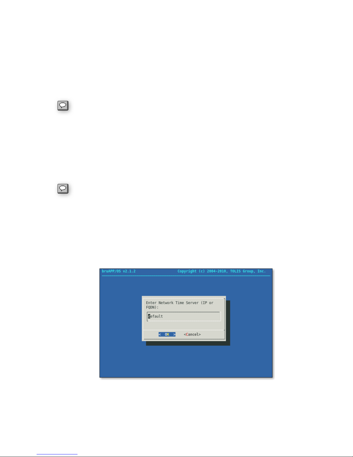
NTP Settings
When using the NTP option of the bruAPP, you may either use the default NTP server (0.pool.ntp.org)
or you may specify an internal NTP server. See figure 8.15.
When specifying your own NTP server, you may either use the IP address of the in-house NTP server
system (no DNS required) or you may enter the hostname (DNS required).
Figure 8.15 — Specifying an NTP server for the bruAPP.
If “default” or the field is left blank, the default NTP server of 0.pool.ntp.org will be used, thus requiring
both internet access on port 123 and DNS services to resolve internet hostnames to IP addresses.
41

After the NTP server has performed itʼs sync operation, the bruAPP/OS will request that
you reboot the system to ensure that all system components are updated with the
proper date and time (including timezone) settings.
Setting the Timezone
You can specify the timezone of the bruAPP by choosing your timezone from the Timezone list. Once
changed, youʼll be asked to reboot the bruAPP to ensure that the timezone settings take effect for all
running services.
Manually Syncing the Time
To manually synchronize the bruAPP system time with the currently defined timezone and NTP server,
choose the “Sync Time” option.
Viewing the Current System Time
To view the current system time, choose the “Current Time” option to view the current date and time of
the bruAPP Backup Appliance.
Viewing the NTP Log
If youʼre having trouble synchronizing the time with the defined NTP server using the current settings,
you can view the NTP log to see what errors, if any, that NTP is reporting.
To scroll through the log, use the up, down, left, and right arrows on your keyboard. If you find an error,
make the appropriate changes to correct the error and try a manual synchronization operation.
Each time the bruAPP synchronizes the time using the NTP server, the system
hardware clock will be updated to ensure that both the software and hardware clocks
remain accurate.
42

Appendix A: End User License Agreement
TOLIS Group, Inc.
LICENSE AGREEMENT
This License Agreement ("Agreement"), provided by TOLIS Group, Inc. ("TOLIS"), governs the use of
the object code version of the BRU brand computer software, documentation and materials
accompanying this Agreement or otherwise provided in connection herewith (collectively, "Software"),
owned by TOLIS, by the person or entity ("Client") that has clicked on the "Agree" button below. For
purposes of this Agreement, Software may be the bruAPP/OS, BRU Sever Server, BRU Server Agent,
or BRU Server Console component.
*************************************************************
IF YOU DO NOT AGREE WITH THESE TERMS YOU MUST NOT USE THE BRUAPP IN ANY
FASHION, CONTACT BRU SALES AND REQUEST RETURN OF THE PRODUCT.
*************************************************************
1. LICENSE AND USE RESTRICTIONS
Subject to all other terms of this Agreement including the payment of any applicable fees, TOLIS hereby
grants to Client a non-exclusive, non-transferable license, without the right to grant sublicenses, to use
one (1) copy of the Software solely for Client's own, internal purposes. The foregoing license includes
the right of Client to make a reasonable number of copies of the computer programs contained in the
Software solely for backup and archival purposes; provided, however, that all such copies shall be
deemed Software for purposes of this Agreement. The foregoing license shall terminate immediately
and without notice for any breach of this Agreement by Client, including any failure to pay fees when
due. Upon any such termination, Client shall immediately destroy or delete any and all Software and
promptly confirm in writing that Client has done so.
The Software is and shall remain the sole and exclusive confidential and proprietary property of TOLIS,
subject to protection under the intellectual property laws of the United States and those throughout the
world. Client agrees not to use or disclose the Software, during and after the term of this Agreement,
except as expressly permitted by this Agreement. Client further agrees not to modify the Software,
remove any notices or markings on the Software, or reverse compile, reverse assemble, reverse
engineer or otherwise attempt to learn or disclose the trade secrets contained in the Software, transfer
the Software in whole or in part over a network, or permit any third party to do any of the foregoing.
Nothing in this Agreement shall be construed as conferring any license under any of TOLIS' intellectual
property rights, whether by estoppel, implication, or otherwise, except for those licenses expressly
granted herein.
2. WARRANTY AND DISCLAIMER
TOLIS warrants that for a period of sixty (60) days from the date of receipt by Client of the Software, the
media on which the Software was delivered shall be without defects in materials or workmanship.
TOLIS agrees to replace any defective media which is returned to TOLIS within the foregoing sixty (60)
day period. TOLIS may make available to Client additional services, including updates, enhancements
or improvements of or to the Software, under separate written agreement, and for additional payment.
THE FOREGOING WARRANTY IS THE ONLY WARRANTY GIVEN HEREUNDER. EXCEPT AS
OTHERWISE PROVIDED ABOVE, THE SOFTWARE IS PROVIDED ON AN "AS IS" BASIS,
WITHOUT ANY WARRANTY WHATSOEVER. ALL EXPRESS, IMPLIED OR STATUTORY
CONDITIONS, REPRESENTATIONS AND WARRANTIES, INCLUDING ANY IMPLIED WARRANTIES
OF MERCHANTABILITY, FITNESS FOR A PARTICULAR PURPOSE, OR NON-INFRINGEMENT, ARE
DISCLAIMED. Some states do not allow the disclaimer of implied warranties, so the foregoing
limitations may not apply to you.
43

3. LIMITATION OF LIABILITY
TOLIS SHALL NOT BE LIABLE FOR ANY INDIRECT, SPECIAL, INCIDENTAL, CONSEQUENTIAL OR
EXEMPLARY DAMAGES ARISING UNDER THIS AGREEMENT OR IN CONNECTION WITH THE
SOFTWARE, REGARDLESS OF WHETHER ADVISED BEFOREHAND OF THE POSSIBILITY OF
SUCH DAMAGES. IN NO EVENT SHALL THE LIABILITY OF TOLIS HEREUNDER EXCEED THE
SUM OF ONE HUNDRED DOLLARS ($100), REGARDLESS OF THE CAUSE OF ACTION, IN TORT,
CONTRACT OR OTHERWISE.
4. GENERAL
Any action related to this Agreement shall be governed by the substantive laws of the State of Arizona,
without regard to conflicts of law principles. The State and Federal courts located in Maricopa County,
Arizona, shall have sole jurisdiction over any dispute arising hereunder, and the parties hereby consent
to the personal jurisdiction of such courts. Neither this Agreement, nor any rights hereunder, may be
assigned by operation of law or otherwise, in whole in part, by Client without the prior, written
permission of TOLIS. Any sale of more than fifty percent (50%) of the common voting stock of, or other
right to control, Client shall be deemed an assignment. Any purported assignment without such
permission shall be void. Any waiver of any rights of TOLIS under this Agreement must be in writing,
signed by TOLIS, and any such waiver shall not operate as a waiver of any future breach of this
Agreement. In the event any portion of this Agreement is found to be illegal or unenforceable, such
portion shall be severed from this Agreement, and the remaining terms shall be separately enforced.
The parties agree that any breach or threatened breach of this Agreement by Client is likely to cause
TOLIS damage that is not fully reparable by payment of damages, and further agree that in such case
TOLIS shall be entitled to seek and obtain injunctive or other equitable relief to protect its rights
hereunder. Client's performance hereunder and use of the Software shall at all times comply with all
applicable laws, rules and regulations, including those governing export of technical information, and
Client shall fully indemnify, defend and hold harmless
TOLIS against any violation thereof. This Agreement is the entire agreement between the parties with
respect to this subject matter, and supersedes any and all prior or contemporaneous, conflicting or
additional communications, negotiations or agreements.
Thank you for doing business with TOLIS Group, Inc.!
TOLIS Group, Inc.
8687 E Via de Ventura
Suite 115
Scottsdale, AZ 85258
bruinfo@tolisgroup.com
http://www.tolisgroup.com
TEL: +1-480-505-0488
FAX: +1-480-505-0492
Additional products and utilities from TOLIS Group that may be used in conjunction with
the bruAPP/OS or BRU Server software may be covered under a different End User
License Agreement(s) (EULA). Please visit http://www.tolisgroup.com/legal/license for
information about other EULA's.
44

Appendix B: Saved Settings
IP Address:
________._________._________._________
Subnet Mask:
________._________._________._________
IP Address:
________._________._________._________
Subnet Mask:
________._________._________._________
Hostname (FQDN):
____________________________________
Gateway IP:
________._________._________._________
DNS 1:
________._________._________._________
DNS 2:
________._________._________._________
DNS 3:
________._________._________._________
Email:
____________________________________
Timezone:
____________________________________
NTP Server:
____________________________________
You may use this page to store all of the settings that have been set on the bruAPP in the event that
you need to reapply the settings.
Network Settings
ETH0 (NIC 1)
ETH1 (NIC 2)
System
RAID Administrator
Date/Time Settings
45

Appendix C: Tape Compatibility Notice
LTO-1 Drive
LTO-2 Drive
LTO-3 Drive
LTO-4 Drive
LTO-5 Drive
LTO-1 Tape
R/W
R/WR―
―
LTO-2 Tape
―
R/W
R/WR―
LTO-3 Tape
――R/W
R/W
R
LTO-4 Tape
―――
R/W
R/W
LTO-5 Tape
――――R/W
LTO Cleani ng
✓✓✓✓✓
Static electricity can cause items such as small pieces of paper or cellophane wrapper pieces to stick to
the cartridge. When cartridges are inserted into the drive, the debris may prevent proper device
functioning and in worst case, damage the device.
To avoid tape device damage, please inspect all cartridges for debris before inserting into the drive, and
store the tapes in their cases.
For units with integrated LTO drives, or attached LTO devices, please review the LTO Tape and Drive
Compatibility matrix (figure 9.1) for LTO tape drive and LTO tape compatibility.
R/W = Read/Write • R = Read • ― = Tape Not Supported • ✓ = Compatible
Figure 9.1 ― LTO Tape and Drive compatibility matrix.
Incompatible Tapes
In the accidental event that you insert an incompatible tape into an LTO tape drive, the drive will
immediately eject the tape. On stand-alone tape drives the “Tape” LED will flash multiple times after the
tape is ejected to inform you of an error.
46

Appendix D: 1-Year Limited Hardware
Warranty
Global Limited Warranty and Technical Support
THIS GLOBAL LIMITED WARRANTY AND TECHNICAL SUPPORT STATEMENT PROVIDES
IMPORTANT INFORMATION ABOUT THE NATURE AND SCOPE OF THE EXPRESS LIMITED
WARRANTY PROVIDED FOR THE TOLIS GROUP PRODUCT, AND ALSO CONTAINS CERTAIN
DISCLAIMERS AND LIMITATIONS OF LIABILITY BY TOLIS GROUP, WHICH MATERIALLY IMPACT
YOUR RIGHTS. ACCORDINGLY, YOU ARE STRONGLY ADVISED TO CAREFULLY READ THIS
GLOBAL LIMITED WARRANTY AND TECHNICAL SUPPORT STATEMENT BEFORE USING YOUR
TOLIS GROUP PRODUCT. YOUR USE OF THE TOLIS GROUP PRODUCT IS DEEMED TO BE
ACCEPTANCE OF THE TERMS AND CONDITIONS SET FORTH IN THIS GLOBAL LIMITED
WARRANTY AND TECHNICAL SUPPORT STATEMENT.
Hardware Limited Warranty
General terms
This TOLIS Group Hardware Limited Warranty gives you, the customer, express limited warranty rights
from TOLIS Group, the manufacturer. In addition, you may also have other legal rights under applicable
local law or special written agreement with TOLIS Group.
TOLIS GROUP MAKES NO OTHER EXPRESS WARRANTY OR CONDITION WHETHER WRITTEN
OR ORAL AND TOLIS GROUP EXPRESSLY DISCLAIMS ALL WARRANTIES AND CONDITIONS
NOT STATED IN THIS LIMITED WARRANTY. TO THE EXTENT ALLOWED BY THE LOCAL LAW OF
JURISDICTIONS OUTSIDE THE UNITED STATES, TOLIS GROUP DISCLAIMS ALL IMPLIED
WARRANTIES OR CONDITIONS, INCLUDING ANY IMPLIED WARRANTIES OR CONDITIONS OF
MERCHANTABILITY, MERCHANTABLE QUALITY, AND FITNESS FOR A PARTICULAR PURPOSE.
FOR ALL TRANSACTIONS OCCURRING IN THE UNITED STATES, ANY IMPLIED WARRANTY OR
CONDITION OF MERCHANTABILITY, SATISFACTORY QUALITY, OR FITNESS FOR A PARTICULAR
PURPOSE IS LIMITED TO THE DURATION OF THE EXPRESS WARRANTY SET FORTH ABOVE.
SOME STATES OR COUNTRIES DO NOT ALLOW.
A LIMITATION ON HOW LONG AN IMPLIED WARRANTY LASTS OR THE EXCLUSION OR
LIMITATION OF INCIDENTAL OR CONSEQUENTIAL DAMAGES FOR CONSUMER PRODUCTS. IN
SUCH STATES OR COUNTRIES, SOME EXCLUSIONS OR LIMITATIONS OF THIS LIMITED
WARRANTY MAY NOT APPLY TO YOU.
FOR CONSUMER TRANSACTIONS IN AUSTRALIA AND NEW ZEALAND, THE LIMITED
WARRANTY TERMS CONTAINED IN THIS STATEMENT, EXCEPT TO THE EXTENT LAWFULLY
PERMITTED, DO NOT EXCLUDE, RESTRICT, OR MODIFY BUT ARE IN ADDITION TO THE
MANDATORY STATUTORY RIGHTS APPLICABLE TO THE SALE OF THIS PRODUCT TO YOU.
THE LIMITED WARRANTY TERMS CONTAINED IN THIS STATEMENT, EXCEPT TO THE EXTENT
LAWFULLY PERMITTED, DO NOT EXCLUDE, RESTRICT, OR MODIFY BUT ARE IN ADDITION TO
THE MANDATORY STATUTORY RIGHTS APPLICABLE TO THE SALE OF THIS PRODUCT TO YOU.
This Limited Warranty is applicable in all countries and may be enforced in any country or region where
TOLIS Group or its authorized service providers offer warranty service for the same product model
number subject to the terms and conditions set forth in this Limited Warranty.
Under the TOLIS Group Global Limited Warranty program, products purchased in one country/region
may be transferred to another country/region, where TOLIS Group or its authorized service providers
47

offer warranty service for the same product model number, without voiding the warranty. Warranty
terms, service availability, and service response times may vary from country/region to country/region.
Standard warranty service response time is subject to change due to local parts availability. Your local
TOLIS Group authorized service provider can provide you with details.
TOLIS Group is not responsible for any tariffs or duties that may be incurred in transferring the
products. Transfer of the products may be covered by export controls issued by the United States or
other governments.
This Limited Warranty applies only to TOLIS Group-branded hardware products (collectively referred to
in this Limited Warranty as “TOLIS Group Hardware Products”) sold by or leased from TOLIS Group,
Inc., its worldwide subsidiaries, affiliates, authorized resellers, or country distributors (collectively
referred to in this Limited Warranty as “TOLIS Group”) with this Limited Warranty. The term “TOLIS
Group Hardware Product” is limited to the hardware components and required firmware. The term
“TOLIS Group Hardware Product” DOES NOT include any software applications or programs, nonTOLIS Group products, or non-TOLIS Group branded peripherals.
All non-TOLIS Group products or non-TOLIS Group branded peripherals external to the TOLIS Group
Hardware Product—such as external storage subsystems, displays, printers and other peripherals—are
provided “AS IS” without TOLIS Group warranty. However, non-TOLIS Group manufacturers and
suppliers or publishers may provide their own warranties directly to you.
TOLIS Group warrants that the TOLIS Group Hardware Products that you have purchased or leased
from TOLIS Group are free from defects in materials or workmanship under normal use during the
Limited Warranty Period. The Limited Warranty Period starts on the date of purchase or lease from
TOLIS Group, or from the date TOLIS Group completes installation. Your dated sales or delivery
receipt, showing the date of purchase or lease of the product, is your proof of the purchase or lease
date. You may be required to provide proof of purchase or lease as a condition of receiving warranty
service. You are entitled to hardware warranty service according to the terms and conditions of this
document if a repair to your TOLIS Group Hardware Product is required within the Limited Warranty
Period.
Unless otherwise stated, and to the extent permitted by local law, new TOLIS Group Hardware Products
may be manufactured using new materials or new and used materials equivalent to new in performance
and reliability. TOLIS Group may repair or replace TOLIS Group Hardware Products (a) with new or
previously used products or parts equivalent to new in performance and reliability, or (b) with equivalent
products to an original product that has been discontinued. Replacement parts are warranted to be free
from defects in material or workmanship for ninety (90) days or, for the remainder of the Limited
Warranty Period of the TOLIS Group Hardware Product they are replacing or in which they are installed,
whichever is longer.
During the Limited Warranty Period, TOLIS Group will, at its discretion, repair or replace any defective
component. All component parts or hardware products removed under this Limited Warranty become
the property of TOLIS Group. In the unlikely event that your TOLIS Group Hardware Product has
recurring failures, TOLIS Group, at its sole discretion, may elect to provide you with (a) a replacement
unit of TOLIS Groupʼs choosing that is the same or equivalent to your TOLIS Group Hardware Product
in performance or (b) to give you a refund of your purchase price or lease payments (less interest)
instead of a replacement. This is your exclusive remedy for defective products.
Exclusions
TOLIS GROUP DOES NOT WARRANT THAT THE OPERATION OF THIS PRODUCT WILL BE
UNINTERRUPTED OR ERROR-FREE. TOLIS GROUP IS NOT RESPONSIBLE FOR DAMAGE THAT
OCCURS AS A RESULT OF YOUR FAILURE TO FOLLOW THE INSTRUCTIONS INTENDED FOR
THE TOLIS GROUP HARDWARE PRODUCT.
48

This Limited Warranty does not apply to expendable or consumable parts and does not extend to any
product from which the serial number has been removed or that has been damaged or rendered
defective (a) as a result of accident, misuse, abuse, contamination, improper or inadequate
maintenance or calibration or other external causes; (b) by operation outside the usage parameters
stated in the user documentation that shipped with the product; (c) by software, interfacing, parts or
supplies not supplied by TOLIS Group; (d) improper site preparation or maintenance; (e) virus infection;
(f) loss or damage in transit; or (g) by modification or service by anyone other than (i) TOLIS Group, (ii)
an TOLIS Group authorized service provider, or (iii) your own installation of TOLIS Group-approved
parts if available for your product in the servicing country or region.
TOLIS GROUP IS NOT RESPONSIBLE FOR DAMAGE TO OR LOSS OF ANY PROGRAMS, DATA,
OR REMOVABLE STORAGE MEDIA. TOLIS GROUP IS NOT RESPONSIBLE FOR THE
RESTORATION OR REINSTALLATION OF ANY PROGRAMS OR DATA OTHER THAN SOFTWARE
INSTALLED BY TOLIS GROUP WHEN THE PRODUCT IS MANUFACTURED.
TOLIS Group is not responsible for any interoperability or compatibility issues that may arise when (1)
products, software, or options not supported by TOLIS Group are used; (2) configurations not supported
by TOLIS Group are used; (3) parts intended for one system are installed in another system of different
make or model.
Exclusive Remedy
TO THE EXTENT ALLOWED BY APPLICABLE LOCAL LAW, THESE TERMS AND CONDITIONS
CONSTITUTE THE COMPLETE AND EXCLUSIVE WARRANTY AGREEMENT BETWEEN YOU AND
TOLIS GROUP REGARDING THE TOLIS GROUP HARDWARE PRODUCT YOU HAVE PURCHASED
OR LEASED. THESE TERMS AND CONDITIONS SUPERSEDE ANY PRIOR AGREEMENTS OR
REPRESENTATIONS—INCLUDING REPRESENTATIONS MADE IN TOLIS GROUP SALES
LITERATURE OR ADVICE GIVEN TO YOU BY TOLIS GROUP OR AN AGENT OR EMPLOYEE OF
TOLIS GROUP—THAT MAY HAVE BEEN MADE IN CONNECTION WITH YOUR PURCHASE OR
LEASE OF THE TOLIS GROUP HARDWARE PRODUCT. No change to the conditions of this Limited
Warranty is valid unless it is made in writing and signed by an authorized representative of TOLIS
Group.
Limitation of liability
IF YOUR TOLIS GROUP HARDWARE PRODUCT FAILS TO WORK AS WARRANTED ABOVE, TOLIS
GROUPʼS MAXIMUM LIABILITY UNDER THIS LIMITED WARRANTY IS EXPRESSLY LIMITED TO
THE LESSER OF THE PRICE YOU HAVE PAID FOR THE PRODUCT OR THE COST OF REPAIR OR
REPLACEMENT OF ANY HARDWARE COMPONENTS THAT MALFUNCTION IN CONDITIONS OF
NORMAL USE.
EXCEPT AS INDICATED ABOVE, IN NO EVENT WILL TOLIS GROUP BE LIABLE FOR ANY
DAMAGES CAUSED BY THE PRODUCT OR THE FAILURE OF THE PRODUCT TO PERFORM,
INCLUDING ANY LOST PROFITS OR SAVINGS, BUSINESS INTERRUPTION, LOSS OF DATA,
LOST REVENUE, LOSS OF USE, OR ANY OTHER COMMERCIAL OR ECONOMIC LOSS OF ANY
KIND, OR SPECIAL, INCIDENTAL, OR CONSEQUENTIAL DAMAGES. TOLIS GROUP IS NOT
LIABLE FOR ANY CLAIM MADE BY A THIRD PARTY OR MADE BY YOU FOR A THIRD PARTY.
THIS LIMITATION OF LIABILITY APPLIES WHETHER DAMAGES ARE SOUGHT, OR A CLAIM
MADE, UNDER THIS LIMITED WARRANTY OR AS A TORT CLAIM (INCLUDING NEGLIGENCE AND
STRICT PRODUCT LIABILITY), A CONTRACT CLAIM, OR ANY OTHER CLAIM. THIS LIMITATION OF
LIABILITY CANNOT BE WAIVED OR AMENDED BY ANY PERSON. THIS LIMITATION OF LIABILITY
WILL BE EFFECTIVE EVEN IF YOU HAVE ADVISED TOLIS GROUP OR AN AUTHORIZED
REPRESENTATIVE OF TOLIS GROUP OF THE POSSIBILITY OF ANY SUCH DAMAGES OR EVEN
IF SUCH POSSIBILITY WERE REASONABLY FORESEEABLE. THIS LIMITATION OF LIABILITY,
HOWEVER, WILL NOT APPLY TO CLAIMS FOR PERSONAL INJURY.
49

THIS LIMITED WARRANTY GIVES YOU SPECIFIC LEGAL RIGHTS. YOU MAY ALSO HAVE OTHER
RIGHTS THAT MAY VARY FROM STATE TO STATE OR FROM COUNTRY TO COUNTRY. YOU ARE
ADVISED TO CONSULT APPLICABLE STATE OR COUNTRY LAWS FOR A FULL DETERMINATION
OF YOUR RIGHTS.
Customer Responsibilities
To enable TOLIS Group to provide the best possible support and service during the Limited Warranty
•
Period, you will be required to:
Maintain a proper and adequate environment, and use the TOLIS Group Hardware Product in
•
accordance with the instructions furnished.
Verify configurations, load most recent firmware, install software patches, run TOLIS Group
•
diagnostics and utilities, and implement temporary procedures or workarounds provided by TOLIS
Group while TOLIS Group works on permanent solutions.
Allow TOLIS Group to keep resident on your systems or sites certain system and network diagnosis
•
and maintenance tools to facilitate the performance of warranty support (collectively referred to as
“Proprietary Service Tools”); Proprietary Service Tools are and remain the sole and exclusive property
of TOLIS Group. Additionally, you will:
Use the Proprietary Service Tools only during the applicable warranty period and only as allowed
by TOLIS Group – Install, maintain, and support Proprietary Service Tools, including any required
updates and patches – Provide remote connectivity through an TOLIS Group-approved
communications line, if required – Assist TOLIS Group in running the Proprietary Service Tools
Use the electronic data transfer capability to inform TOLIS Group of events identified by the
software
Purchase TOLIS Group-specified remote connection hardware for systems with remote diagnosis
service, if required
Return the Proprietary Service Tools or allow TOLIS Group to remove these Proprietary Service
Tools upon termination of warranty support
Not sell, transfer, assign, pledge, or in any way encumber or convey the Proprietary Service Tools
-
In some cases, TOLIS Group may require additional software such as drivers and agents to be
•
loaded on your system in order to take advantage of these support solutions and capabilities.
Use TOLIS Group remote support solutions where applicable. TOLIS Group strongly encourages you
•
to use available support technologies provided by TOLIS Group. If you choose not to deploy available
remote support capabilities, you may incur additional costs due to increased support resource
requirements.
Cooperate with TOLIS Group in attempting to resolve the problem over the telephone. This may
•
involve performing routine diagnostic procedures, installing additional software updates or patches,
removing third-party options, and/or substituting options.
Make periodic backup copies of your files, data, or programs stored on your hard drive or other
•
storage devices as a precaution against possible failures, alteration, or loss. Before returning any
TOLIS Group Hardware Product for warranty support, back up your files, data, and programs, and
remove any confidential, proprietary, or personal information.
Maintain a procedure to reconstruct your lost or altered files, data, or programs that is not dependent
•
on the TOLIS Group Hardware Product under warranty support.
Notify TOLIS Group if you use TOLIS Group Hardware Products in an environment that poses a
•
potential health or safety hazard to TOLIS Group employees or subcontractors. TOLIS Group may
require you to maintain such products under TOLIS Group supervision and may postpone warranty
service until you remedy such hazards.
Perform additional tasks as defined within each type of warranty service listed below and any other
•
actions that TOLIS Group may reasonably request in order to best perform the warranty support.
Types of Hardware Warranty Service
Listed below are the types of warranty services that may be applicable to the TOLIS Group Hardware
Product you have purchased. For more details, refer to the Limited warranty period section.
50

Parts-only warranty service
Your TOLIS Group Limited Warranty may include a parts-only warranty service. Under the terms of
parts-only service, TOLIS Group will provide replacement parts free of charge. If TOLIS Group carries
out the repair, labor and logistics costs are at your expense.
Advanced unit replacement warranty service
Your TOLIS Group Limited Warranty may include an advanced unit replacement warranty service.
Under the terms of the advanced unit replacement warranty service, TOLIS Group will ship a
replacement unit directly to you if the TOLIS Group Hardware Product you purchased is diagnosed as
defective. On receiving the replacement unit, you will be required to return the defective unit back to
TOLIS Group, in the packaging that arrives with the replacement unit, within a defined period of time,
normally seven (7) calendar days. TOLIS Group will incur all shipping and insurance costs for ground
delivery to you, however, shipping, insurance and logistic charges for return of the defective unit to
TOLIS Group are your responsibility. Second-day, next-day and same-day delivery options are also
available for for an additional charge.
For advanced unit replacement warranty, a valid credit card is required. TOLIS Group reserves the right
to place a hold on the provided credit card for the full replacement cost of the replacement unit. If the
defective unit has not been received by TOLIS Group after fourteen (14) calendar days, the credit card
provided will be charged the full replacement cost of the replacement unit.
51
 Loading...