

Toleko A131 Instruction Manual
Generalagent i Sverige: TOLEKA AB – Fenix väg 28 – 134 44 GUSTAVSBERG
Tel. 08 574 103 50 – Fax. 08 570 349 22 – info@toleka.se - www.toleka.se
INSTRUCTION MANUAL
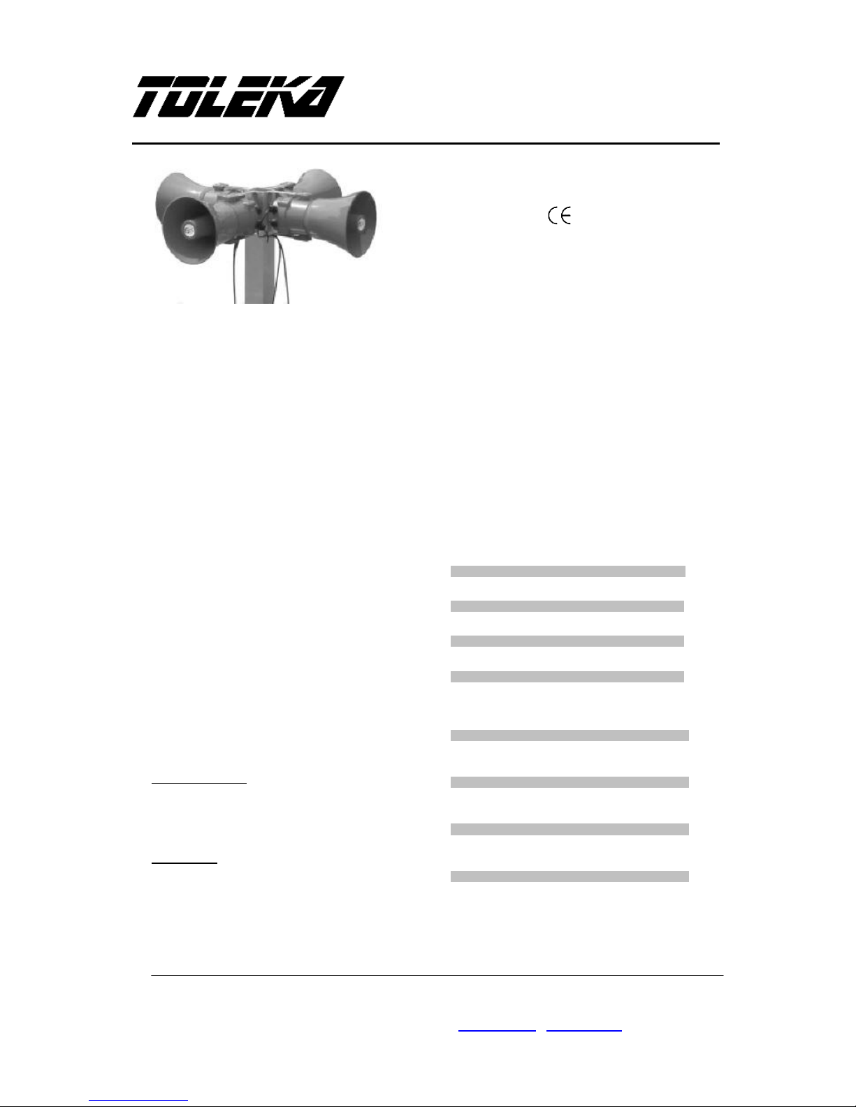
A131 High Level Audible Warning System
Weight: 1.5kg single AC unit
2.9kg four way AC unit
Marking:
3) Installation Requirements
1) Introduction
The A131 high level audible warning system is an
effective wide area warning alarm system and
can be used where there is a requirement to
attract attention over large areas and also where
potential high levels of background noise exist.
The system comprises of a central control unit
which is configured to drive between one and four
synchronized audible horns.
The control unit produces forty five different alarm
sounds (tones) that are selectable using an
internal dipswitch (see tone table page 3 for
available tones) including a stage 2 and stage 3
alarm option.
Each audible horn is capable of producing a
range of loud warning signals with output levels
at one meter of approximately 131dB(A)
depending on tone selected.
Both the control unit and horns are suitable to
mount either indoors or outdoors in a number of
mounting configurations with ingress protection to
IP66.
2) Operating and Marking
All units have the following operating
requirements and limitations.
Audible Horn Units
Unit Type No.: A131
Operating Temp: -20 to +55°C
IP Rating: IP66
Weight: 4.7kg per horn
Control Panel
Unit Type No. A131xxxxxGx (dependent on
variant chosen see table 1)
Input Voltage:
24V DC (18V to 30V DC range)
115 or 230VAC (90V to 264V AC range)
Operating Temp: -20 to +55°C
IP Rating: IP66
Always de-energize control unit before removing
cover.
The installation of the units must be in
accordance with any local codes that may apply
and should only be carried out by a competent
electrical engineer who has the necessary
training.
3) Power Supply Selection
It is important that a suitable power supply is run
the control unit. The power supply selected must
have the necessary capacity to provide the input
current to the control unit.
The following table shows the input current taken
by the various control unit configurations units:-
DC Unit Type Input Input Range. No.
Horns Voltage Current I/P Volts
A131DC24G1 18-30V DC
1 Horn Unit 24V DC 3.2A
A131DC24G2 18-30V DC
2 Horn Units 24V DC 6.5A
A131DC24G3 18-30V DC
3 Horn Units 24V DC 9.8A
A131DC24G4 18-30V DC
4 Horn Units 24V DC 13.2A
AC Unit Type Input Input Range. No.
Horns Voltage Current I/P Volts
A131AC230G1 90-264V AC
1 Horn Unit 115V AC 0.78A
1 Horn Unit 230V AC 0.39A
A131AC230G2 90-264V AC
2 Horn Units 115V AC 1.60A
2 Horn Units 230V AC 0.78A
A131AC230G3 90-264V AC
3 Horn Units 115V AC 3.9A
3 Horn Units 230V AC 1.5A
A131AC230G4 90-264V AC
4 Horn Units 115V AC 4.2A
4 Horn Units 230V AC 1.95A
Table 1: Control Unit variants and power
requirements

Generalagent i Sverige: TOLEKA AB – Fenix väg 28 – 134 44 GUSTAVSBERG
Tel. 08 574 103 50 – Fax. 08 570 349 22 – info@toleka.se - www.toleka.se
INSTRUCTION MANUAL
A131 High Level Audible Warning System
Current levels shown above are for the nominal
input voltage. The input current will vary
according to the voltage input level and the tone
selected.
The above table also shows the maximum and
minimum voltages at which the control units can
be operated.
4) Cable Selection
When selecting the cable size consideration must
be given to the input current that the control unit
draws (see table above) and the length of the
cable run.
5) Earthing
AC powered control units must be connected to a
good quality earth. The unit is provided with
internal earthing terminal which is located next to
the power terminal (See figure 4).
6) Horn Location and Mounting
The location of the horns should be made with
due regard to the area over which the warning
signal must be audible. The horns should only be
fixed to services that can carry the weight of the
unit.
The horns should be securely bolted to a suitable
surface using the 7mm diameter bolt holes in the
stainless steel U shaped mounting bracket (see
figure 1). The angle can then be adjusted in the
direction that the sound is primarily required to
cover. This can be achieved by loosening the two
large bracket screws in the side of the unit, which
allow adjustment in steps of 18°. On completion
of the installation the two large bracket
adjustment screws on the side of the unit must be
fully tightened to ensure that the unit cannot
move in service.
7) Control Unit Location and Mounting
The location of the control unit will depend on the
level of customer accessibility required. The
control unit should only be fixed to services that
can carry the weight of the unit.
The control unit is mounted using 4 off suitable
screws in the mounting positions given on
installation figures 2 & 3.
Fig 1 Horn Installation
Fig 2 Multi-horn Control Unit mounting Installation
A131xxxxxG2, G3 & G4
 Loading...