

Tokyo Sokki Kenkyujo TC-32K Operation Manual

Operation Manual
TC-32K
HANDHELD
DATA LOGGER
This indication shows any matters to understand this content deeply and the
useful information.
This indication shows any attention or supplement to avoid erroneous operation
etc.
✍
If you ignore this indication and use this system in an improper way, it may
cause danger which will result in injury.
If you ignore this indication and use this system in an improper way, it may
cause danger which will result in death or serious injury.
If you ignore this indication and use this system in an improper way, it may
cause the occurrence of physical obstacles.
Danger
Warning
Caution
Note
NOTICE
This manual describes how to operate Handheld Data Logger TC-32K and its operation
procedures. Please read this operation manual thoroughly to familiarize yourself with the
functions and operating procedures of this product. It will enable you to make maximum use
of all its functions and take precise measurements effectively.
Please keep this manual always ready to use.
When you read this manual
This manual uses following symbols to describe important items. Please read carefully.
Reproduction or reprinting of this instruction manual, either partially or totally, without
permission from Tokyo Sokki Kenkyujo Co., Ltd. is strictly prohibited.
The contents of this instruction manual are subject to change without notice for the purpose of
product improvement.
If you have any questions or comments regarding contents of this manual such as
misdescription, inaccuracy and missing items, please feel free to contact us.
The company and product names referred to in this manual represent trade names or
registered trademarks.
This operation manual applies to the software version 1.2.
Safety Precautions
Powder or dust inside the system may cause poor contact or a lowered
insulation effect in the connector. Pay special attention, during use and
storage, not to allow dust to enter the system.
Do not operate the system in a place where there is flammable gas or
flammable steam. This may cause fire.
Danger
Operate the system at a specified temperature. If the operating site is
exposed to direct sunlight or an extremely low temperature, arrange for shade
or a thermal insulating material.
It is not recommended for the user to disassemble or remodel the system.
Such a do-it-yourself action may cause an electric shock or a malfunction.
Never connect the grounding cable to a gas pipe. In addition, make it a rule
to disconnect the power supply cable before connecting or disconnecting the
grounding cable. There is danger of a fire and the electric shock.
Operate the system at a relative humidity less than 85%. Do not expose it to
rain or extreme humidity. When water flowed into the system or system is
flooded, dry enough before turning on the power supply. If the system does
not start normally, some trouble might be caused. Please contact us.
Warning
The system may malfunction if either the unit or its wiring is placed near such
machines as a large motor, crane, transformer, or welding machine. When
extending the sensor to a place subject to a strong electric field, such as near
a power substation or radio transmission station, use a special cable such as
The system is vulnerable to the dielectric effect of thunderbolts. Take
preventive measures against thunderbolts where applicable. Contact your
dealer or Tokyo Sokki Kenkyujo for details.
Danger
Danger
Caution
Caution
Caution
Caution
Do not forcibly drag the system with connection cables connected. The
cables may be damaged and/or the connectors may be disconnected. In
addition, do not apply impact to the connector of the cable. Keep the
connectors away from soil, mud, water and oil.
Caution
The range of power supply voltage for this system is DC 9~18 V.
Malfunction may be caused if larger voltage is supplied. If the system is
used in a positive grounded vehicle, do not contact the housing of this system
with the body of the vehicle.
Caution

NOTICE
Safety Precautions
Table of Contents
Table of Contents
Chapter 1 Overview
1.1 Overview ································································································ 1 - 2
1.2 Features ································································································· 1 - 2
1.3 Details about each part ············································································· 1 - 3
Front and side ·················································································· 1 - 3
Top, bottom, and back ········································································ 1 - 4
Chapter 2 Preparation
2.1 Instructions for use ··················································································· 2 - 2
2.2 Power Source ·························································································· 2 - 3
How to set batteries ··········································································· 2 - 3
Operating time by batteries ································································· 2 - 4
Connection for AC adapter ·································································· 2 - 5
Power ON/OFF ················································································· 2 - 5
2.3 Instructions for field measurement ······························································· 2 - 6
Grounding ······················································································· 2 - 6
Lightning protection ··········································································· 2 - 6
2.4 Screen outline ························································································· 2 - 7
Startup screen ·················································································· 2 - 7
Screen configuration ·········································································· 2 - 7
2.5 Operation outline ······················································································ 2 - 8
Operation system ·············································································· 2 - 8
Key switch ······················································································· 2 - 9
Key lock ·························································································· 2 - 9
Chapte 3 Sensor Connection
3.1 Sensor connection ··················································································· 3 - 2
How to use input terminal block ···························································· 3 - 2
Wire connection by sensor type ··························································· 3 - 3
Chapter 4 Monitor Display and Measurement
4.1 Monitor screen outline ··············································································· 4 - 2
4.2 Monitor display ························································································ 4 - 2
Value monitor ··················································································· 4 - 2
Waveform monitor ··········································································· 4 - 3
Meaning of displayed value ······························································· 4 - 3
Monitor type selection ······································································ 4 - 4
Waveform monitor setting ································································· 4 - 4
4.3 Initial value processing ············································································ 4 - 5
Initial-in ························································································· 4 - 5
Initial-in of monitor channel ······························································· 4 - 6
Rewrite of initial value ······································································ 4 - 7
4.4 Channel setting ······················································································ 4 - 8

Measurement mode ········································································· 4 - 8
Switching of measurement mode ························································ 4 - 8
Channel setting in single channel mode ················································· 4 - 9
4.5 Record of measurement value ··································································· 4 -10
Manual measurement ······································································· 4 -10
Auto measurement ··········································································· 4 -11
4.6 Sub LCD ······························································································· 4 -11
Chapter 5 Measurement Setting
5.1 Measurement setting outline ······································································· 5 - 2
5.2 Sensor mode ··························································································· 5 - 3
Sensor mode ···················································································· 5 - 3
Sensor mode setting ·········································································· 5 - 4
Group setting ··················································································· 5 - 5
5.3 Coefficient, indication digits, and unit ···························································· 5 - 6
Parameters ······················································································ 5 - 6
Parameter setting example ································································· 5 - 6
Coefficient, indication digits, and unit setting ··········································· 5 - 7
Coefficient setting by Cap/RO ······························································ 5 - 9
Check of coefficient ·········································································· 5 -10
5.4 Thermocouple RJC setting ········································································ 5 -11
5.5 TEDS sensor ·························································································· 5 -12
Reading of sensor setting ·································································· 5 -12
Applying the read setting ··································································· 5 -13
5.6 Switching of measurement mode ································································ 5 -13
5.7 Switching between Measure and Direct ······················································· 5 -14
5.8 Automatic measurement ··········································································· 5 -15
Interval measurement ······································································· 5 -15
Interval timer setting ········································································· 5 -15
Real-time start setting ······································································· 5 -17
Goto Step ······················································································· 5 -18
Goto Step setting ············································································· 5 -19
Start and stop of interval measurement ················································· 5 -20
Sleep function ················································································· 5 -21
5.9 Various checks ······················································································· 5 -22
Insulation check ··············································································· 5 -22
Resistance check ············································································· 5 -22
Dispersion check ·············································································· 5 -23
Lead wire resistance check ································································ 5 -23
Bridge output check ·········································································· 5 -23
Coefficient setting check ···································································· 5 -24
5.10 Measurement auxiliary setting ·································································· 5 -24
Simple measure setting ····································································· 5 -24
Comet setting ·················································································· 5 -26
Power source frequency of measurement environment ···························· 5 -26
Initial-in permission ··········································································· 5 -27
Burnout check setting ········································································ 5 -27

Chapter 6 Record Setting
6.1 Record setting outline ··············································································· 6 - 2
6.2 Data memory ·························································································· 6 - 3
Data memory structure ······································································· 6 - 3
Readout of data ················································································ 6 - 4
Data memory setting ·········································································· 6 - 4
Deletion of data in data memory ··························································· 6 - 5
Printout of data memory ····································································· 6 - 5
6.3 CF card ·································································································· 6 - 6
Readout of data ················································································ 6 - 6
File name and file format setting ··························································· 6 - 7
File deletion ····················································································· 6 - 9
Saving data file ················································································· 6 - 9
Reading of setting file ········································································ 6 -10
CF card formatting ············································································ 6 -10
6.4 File copy ······························································································· 6 -11
6.5 Recording in data memory and CF card ······················································· 6 -12
Chapter 7 Interface Setting
7.1 Interface setting outline ············································································· 7 - 2
7.2 RS-232C setting ······················································································ 7 - 3
Communication conditions ·································································· 7 - 3
7.3 Data output ····························································································· 7 - 4
Connection with device ······································································ 7 - 4
Data output destination and output procedure ········································· 7 - 4
7.4 Data output format setting ·········································································· 7 - 5
7.5 External indicator setting ··········································································· 7 - 6
7.6 Cautions for printer setting ········································································· 7 - 6
7.7 Remote measurement ··············································································· 7 - 7
Configuration ···················································································· 7 - 7
Function ·························································································· 7 - 7
Chapter 8 Other Settings
8.1 Other setting outline ················································································· 8 - 2
8.2 Auto power-off setting ··············································································· 8 - 3
8.3 Version information ·················································································· 8 - 4
8.4 Date and time setting ················································································ 8 - 4
8.5 Switching between Japanese and English ····················································· 8 - 5
8.6 Maintenance ··························································································· 8 - 6
LCD backlight setting ········································································· 8 - 6
LCD backlight brightness ···································································· 8 - 7
Contrast setting ················································································ 8 - 7
Buzzer volume setting ········································································ 8 - 8
Upgrading ························································································ 8 - 8
8.7 Factory setting ························································································ 8 -10
Execution of factory setting ································································ 8 -10
List of factory setting ········································································· 8 -11

Chapter 9 Increase of the Number of Measurement Points
9.1 Outline of increase of the number of measurement points ································ 9 - 2
Options to increase the number of measurement points ···························· 9 - 2
9.2 Switching box ·························································································· 9 - 3
CSW-5B connection ·········································································· 9 - 3
Data memory ··················································································· 9 - 3
Measurement mode setting ································································· 9 - 4
Channel setting ················································································· 9 - 4
Box number setting ············································································ 9 - 4
Monitor display ················································································· 9 - 5
Monitor type selection ········································································ 9 - 5
Initial value processing ······································································· 9 - 6
Program setting ················································································ 9 - 6
Record of measurement value ····························································· 9 - 7
Various checks ················································································· 9 - 7
9.3 Inclinometer adapter ················································································· 9 - 8
IA-32 connection ··············································································· 9 - 8
Data memory ··················································································· 9 - 8
Measurement mode setting ································································· 9 - 9
Channel setting ················································································· 9 - 9
Monitor display ················································································· 9 - 9
Program setting ··············································································· 9 -10
Record of measurement value ···························································· 9 -10
Unavailable function in inclinometer mode ············································· 9 -11
Chapter 10 Strain Compensation
10.1 Wire connection of strain gauge ······························································· 10 - 2
1-gauge 4-wire method ····································································· 10 - 2
Quarter bridge 2-wire method ····························································· 10 - 2
Quarter bridge 3-wire method ····························································· 10 - 2
Half bridge method ··········································································· 10 - 2
Full bridge method ············································································ 10 - 2
10.2 Sensitivity drop due to sensor cable extension ············································ 10 - 3
Measurement by constant voltage method ············································ 10 - 3
Measurement by constant current method ············································· 10 - 5
10.3 Complete Compensation Method of Strain (Comet) ······································ 10 - 7
Compensation method in quarter bridge 3-wire method ··························· 10 - 7
Comet NON ···················································································· 10 - 8
Comet A ························································································· 10 - 8
Comet B (Quarter bridge 3-wire method only) ········································ 10 - 8
10.4 How to find the lead wire resistance ·························································· 10 - 9
10.5 Compensation method in 1-gauge 4-wire method ······································· 10 -10
Chapter 11 Specifications
11.1 Specifications ······················································································· 11 - 2
11.2 Standard accessories ············································································· 11 - 6
11.3 Option ································································································· 11 - 7
11.4 Outside drawing ···················································································· 11 - 8

Chapter 12 Error Message
12.1 Explanations and countermeasures for error messages ································ 12 - 2

Chapter 1
Overview
1.1 Overview ···················································· 1 - 2
1.2 Features ···················································· 1 - 2
1.3 Details about each part ·································· 1 - 3

1.1 Overview
1-2
1.1 Overview
TC-32K is a compact hand held instrument that you can hold with one hand. Its splash proof construction
allows safety use outside. The terminals connecting the sensors are one-touch type, and provide easy
connection with the lead wires and banana plugs, and speedy measurement. You can set the sensor mode,
coefficient, and initial values of up to 20 channels and record their data, so it is easy to organize the data
even when you are moving around multiple fields to collect data. Also, by using a dedicated switching
box CSW-5B/CSW-5B-05, auto measurement of 5 points becomes available. In addition, TC-32K has
various functions including the interval timer, data memory, data storage by Compact Flash
card, and connection with PC for control and data transfer. With the resistance check and insulation
resistance check functions, you can check strain gauges and strain gauge type transducers.
TM
memory
1.2 Features
▪ Good for measuring strain, DC voltage, thermocouple, Pt-RTD (platinum resistance temperature
detector), resistance, and insulation resistance
▪ Provides insulation resistance measurement to enable sensor check
▪ Supports 1-gauge 4-wire strain measurement method
▪ TEDS compatible
▪ Quick connection of a cable without connector
▪ Auto measurement by interval timer
▪ Low power consumption
▪ Simple replaceable power source, four size AA batteries
▪ Combination with the switching box CSW-5B/CSW-5B-05 provides multiple points measurement
▪ Combination available with adaptor for 2-directional inclinometer
1-3
1.3 Details about each part
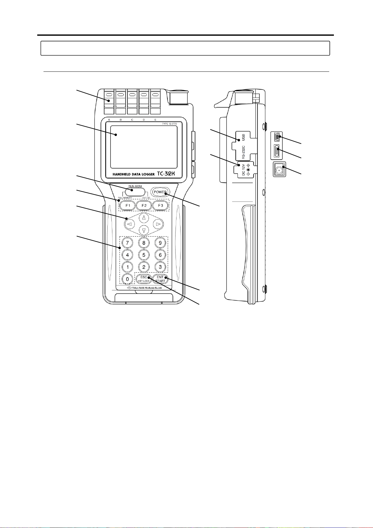
1: Input terminal Connects strain gauges and various sensors.
2: Main LCD Displays monitored measurement values and provides various settings.
3: Sub LCD Displays the timer operation and memory status.
4: POWER key Main power switch
5: Function key Switches the functions.
6: Cursor key Moves the cursor.
7: Ten keys Used for input of values and selection of menu items.
8: ENT key Used to fix the setting values, and to start of the timer.
9: ESC key Used for cancellation of settings, and escape from each menu.
10: I/F connector cap Protection cap for interface connector
11: DC connector cap Protection cap for DC input connector
12: USB connector Connector for USB
13: RS-232C connector Connector for RS-232C
14: DC input connector Connector for AC adapter
1
2
3
4
5
6
8
9
12 7 13
14
10
11
■ Front and side
1.3 Details about each part
1.3 Details about each part
1-4
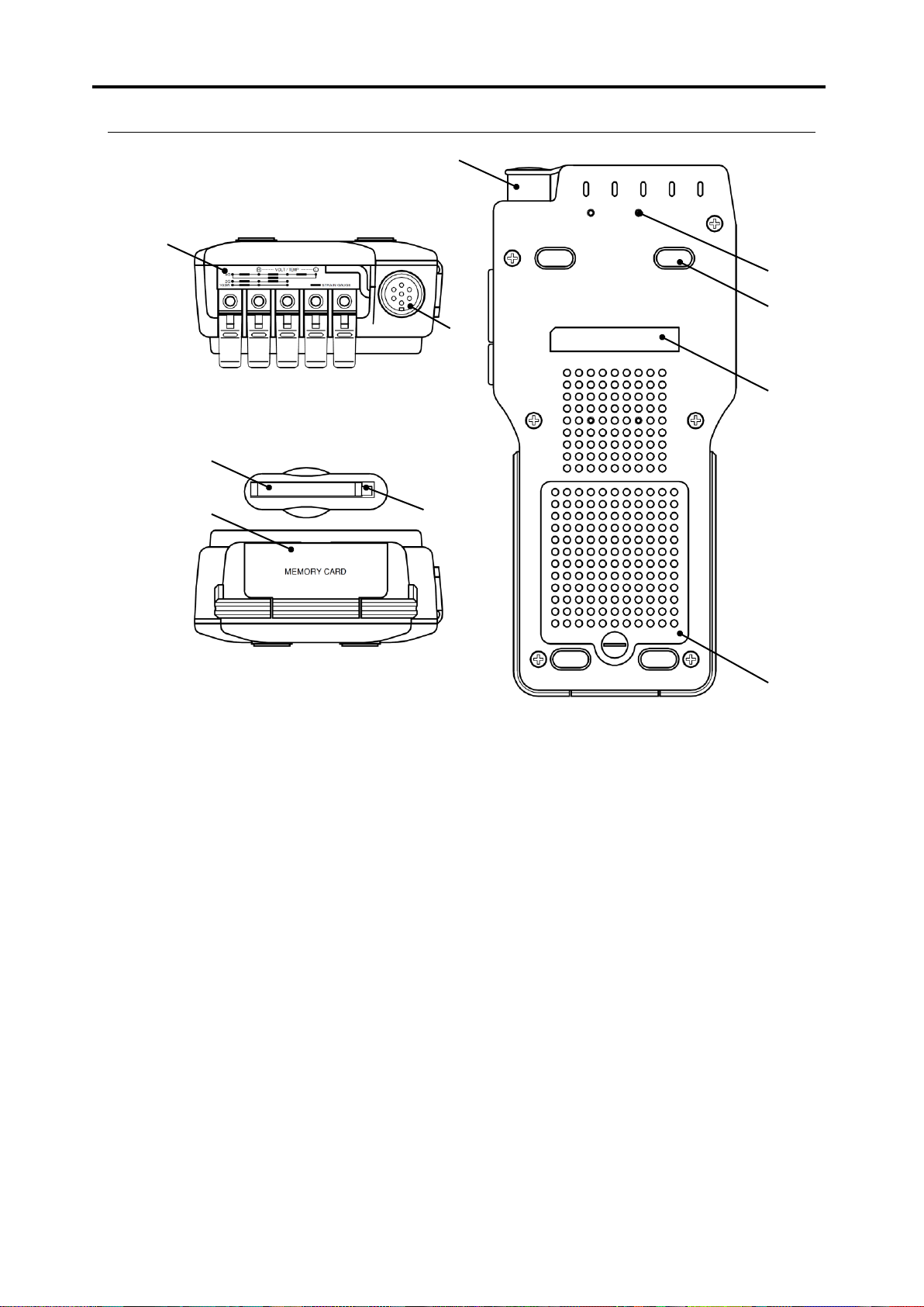
1: Wire connection label Shows how to connect wires of strain gauges.
2: Input connector NDIS connector receptacle for connecting strain gauge type transducer
3: CF card*slot Slot for memory card based on CF card TYPE I
4: Eject button Double-push button to remove a CF card
5: CF cover Protection cover for CF card slot
6: NDIS connector cap Protection cap for NDIS connector receptacle
7: Fixing thread Used for fixing of the main body (effective screw depth: 5mm)
8: Nonslip rubber Rubber sheet for anti slip
9: Serial Number This is the serial number of the instrument.
10: Battery hatch Removed when batteries are replaced.
* CF card: CompactFlash
TM
memory card (hereafter abbreviated as CF card)
1
2 3 7
8
10
9 4 6
5
■ Top, bottom, and back

Chapter 2
Preparation
2.1 Instructions for use ······································· 2 - 2
2.2 Power source ·············································· 2 - 3
2.3 Instructions for field measurement ··················· 2 - 6
2.4 Screen outline ············································· 2 - 7
2.5 Operation outline ·········································· 2 - 8

2.1 Instructions for use
2-2
Note
Do not use the instrument in places affected by strong or continuous vibrations. Do
not drop the instrument during transportation. Do not give strong impact to the
instrument. Otherwise, the instrument may be damaged.
Warning
Before transportation, pack the instrument with packing materials for delivery or other
materials as needed to protect the instrument from vibration and crash.
Do not put a heavy thing on the instrument.
When the body of the instrument gets dirty, wipe away lightly with soft cloth
moistened with diluted mild detergent and then wipe off the moisture with a dry cloth.
Do not use a strong solvent like thinner, which may damage or change the color of
the body of the instrument.
With the connector capped, this instrument is equivalent to IP-54 (not affected by
water splash from any direction). Do not let the instrument soak directly in water.
For waterproof, the connector cap and the CF cover must be attached correctly.
The eject button used for removing a CF card may be broken easily by external force
when the button is in projected position. Always keep the button depressed inside.
Do not insert anything other than CF cards in the CF card slot.
The liquid crystal display consists of the number of pixels. In some cases, there are
some pixels that always light up or always black out. Such pixels are called stuck
pixels. Please note that they are not a failure but a characteristic of liquid crystal
display, and that stuck pixels are not initial failure, and not covered by our repair or
exchange services.
Please wait 5 or more seconds after you pull out or insert a CF card. Otherwise, the
instrument cannot recognize the CF card. Also, do not remove the CF card or turn
off the power when data are being written into the CF card.
Warning
Warning
Warning
Warning
Warning
Note
2.1 Instructions for use
Please pay attention to the following information when using this instrument.

2.2 Power source
2-3
1) Rotate the screw anticlockwise with a coin or
something and remove the battery hatch.
Loosened
2) Set four batteries in correct positions.
3) Return the battery hatch and rotate the screw
clockwise to lock the hatch.
In order to prevent blowout or leakage of batteries:
▪ Check the + indication and the – indication, and set them in the right positions.
▪ Do not mix different battery models or new and old batteries.
▪ When you do not use the instrument for a long time, remove batteries from the
main body.
Warning
2.2 Power source
This instrument is driven by four AA size batteries or an optional AC adapter.
■ How to set batteries
You can use size AA alkaline batteries or rechargeable batteries for this instrument. This instrument does
not have function to charge the batteries set inside. When using rechargeable batteries, charge them in
advance.
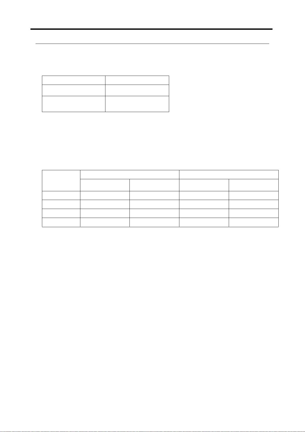
2-4
Condition
Alkaline battery
Single unit of TC-32K
10 hours
TC-32K + CSW-5A or
CSW-5B
6 hours
Interval time
Ambient temperature: 23°C
Ambient temperature: 0°C
Single unit of
TC-32K
+ CSW-5A or
CSW-5B
Single unit of
TC-32K
+ CSW-5A or
CSW-5B
1 minute
60 hours (2.5 days)
43 hours (1.8 days)
42 hours (1.75 days)
30 hours (1.2 days)
10 minutes
580 hours (24 days)
428 hours (17 days)
400 hours (16 days)
300 hours (12 days)
1 hour
2800 hours (116 days)
2400 hours (100 days)
1960 hours (81 days)
1680 hours (70 days)
3 hours or more
7200 hours (300 days)
6000 hours (250 days)
5000 hours (208 days)
3500 hours (145 days)
■ Operating time by batteries
Operating time by batteries varies depending on ambient temperature and other factors. The list below
shows standard operating time when using new alkaline batteries.
Operating time in continuous use
The operating time above is on the following conditions.
* The auto power-off function is not used.
* The LCD backlight is OFF.
* The monitor display is ON.
* The CF card is in the slot.
* Ambient temperature is 23°C.
Operating time using sleep-interval
* The operating time above is by using alkaline batteries.
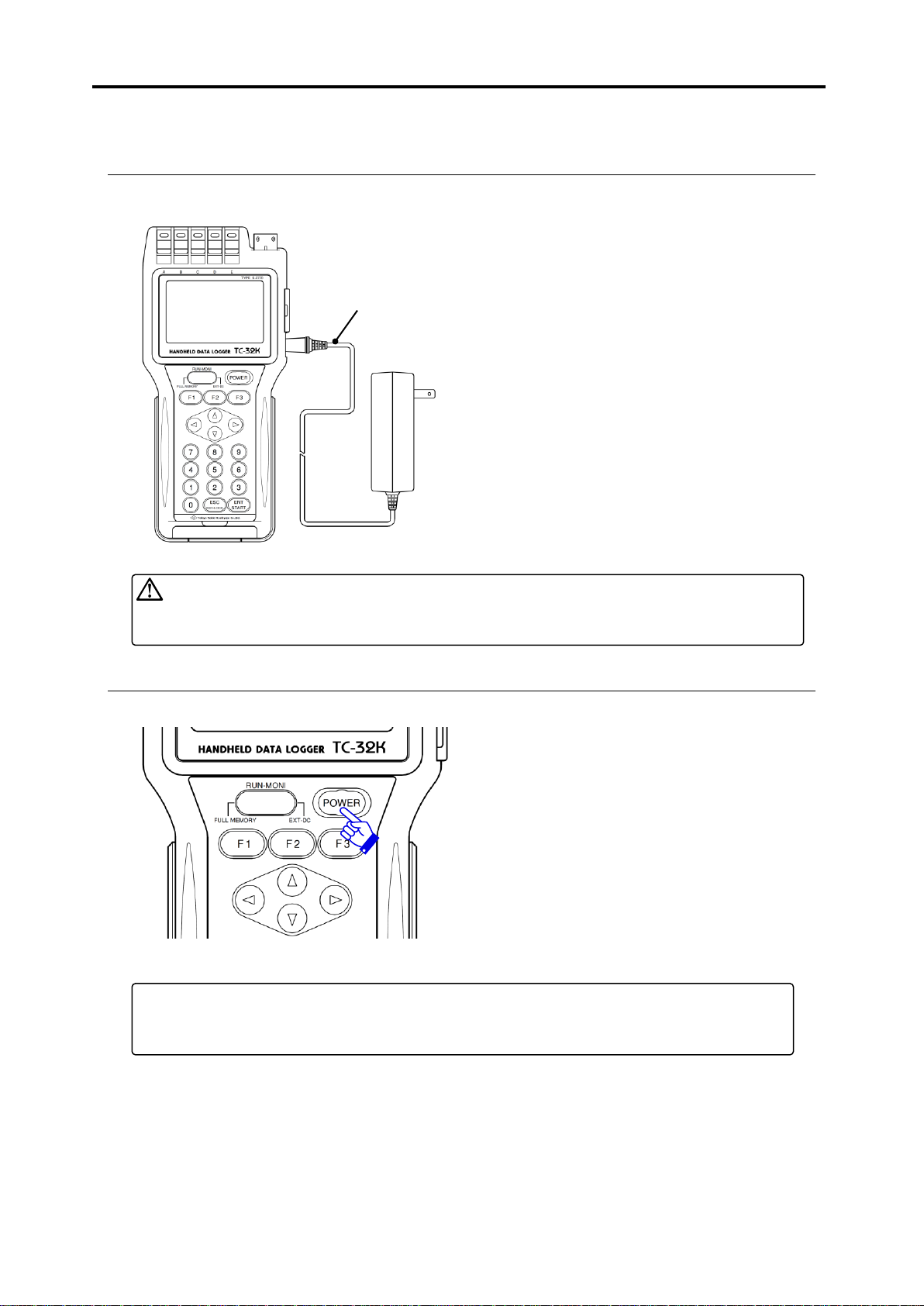
2-5
Remove the connector cap and connect the
AC adapter “CR-1869” to the DC input
connector on the main body. Then, connect
the AC adapter unit to the 100~240 V AC
wall socket. Even if batteries are set in the
TC-32K, power supply from the AC adapter
is prioritized.
Power ON
Press the [POWER] key for 2 seconds or
more. The startup screen appears on the
main LCD and then, the monitor screen is
displayed.
Power OFF
Press the [POWER] key for 2 seconds or
more.
To repeat turning ON/OFF power excessively fast imposes a burden on the
instrument. Wait for more than 5 seconds before power-on after shut-down, or
shut-down after power-on.
Note
▪ Do not use any AC adapter other than “CR-1869.”.
▪ Connect the AC adapter to the main body first and then, connect it to the 100~240 V
AC wall socket.
Warning
CR-1869
To AC100~240V
wall socket
■ Connection of AC adapter
The AC adapter “CR-1869” is an optional product.
■ Power ON/OFF
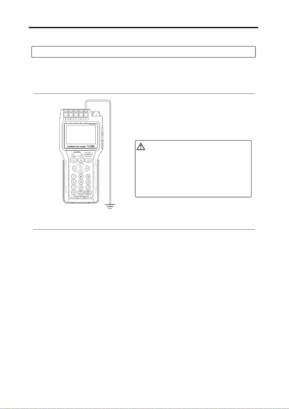
2.3 Instructions for field measurement
2-6
Connect the earth wire to the input terminal E. Use a thick
earth wire as much as possible and ground with the
shortest length. Grounding is also effective for
prevention of noise from lightning or heavy equipments.
If peal of thunder is near, or there is a
risk of lightning stroke, stop the
wiring works for grounding and
power source, operation of the
instruments, and keep away from the
instruments. If being hit by a stroke
of lightning during these works, you
may get an electric shock, get
burned, or even die.
Danger
2.3 Instructions for field measurement
When installing the TC-32K together with the switching box CSW-5A or CSW-5B for long-term
measurement, be sure to arrange grounding correctly. Also, if there is a risk of lightning stroke, be sure to
ground correctly.
■ Grounding
■ Lightning protection
In fields where cables between switching boxes and sensors are extended, pulse generated by induction of
lightning stroke may cause serious damage on sensors, switching boxes and instrument, and even break
them even if they are not hit by lightning stroke directly. Therefore, proper countermeasures against
lightning are essential.
Cable layout
For sensor cables, use dedicated cables for transducers such as rubber sheathed shielded cable. In
order to minimize the difference of induction voltage against the ground, avoid wiring in midair, and
lay wires down on the ground. If it is impossible to lay them down on the ground (for example if
cables are installed around steel towers), use the arrester for sensors mentioned in the next article.
Arrester for sensor
NZ-6B is the 6-wire system arrester for strain gauge type transducers and also applied to strain gauges.
Insert the arrester near the sensor as much as possible. Although the input terminals of TC-32K have
simple built-in arresters for sensor, it is recommended to install another arrester for sensor together to
make assurance double sure.
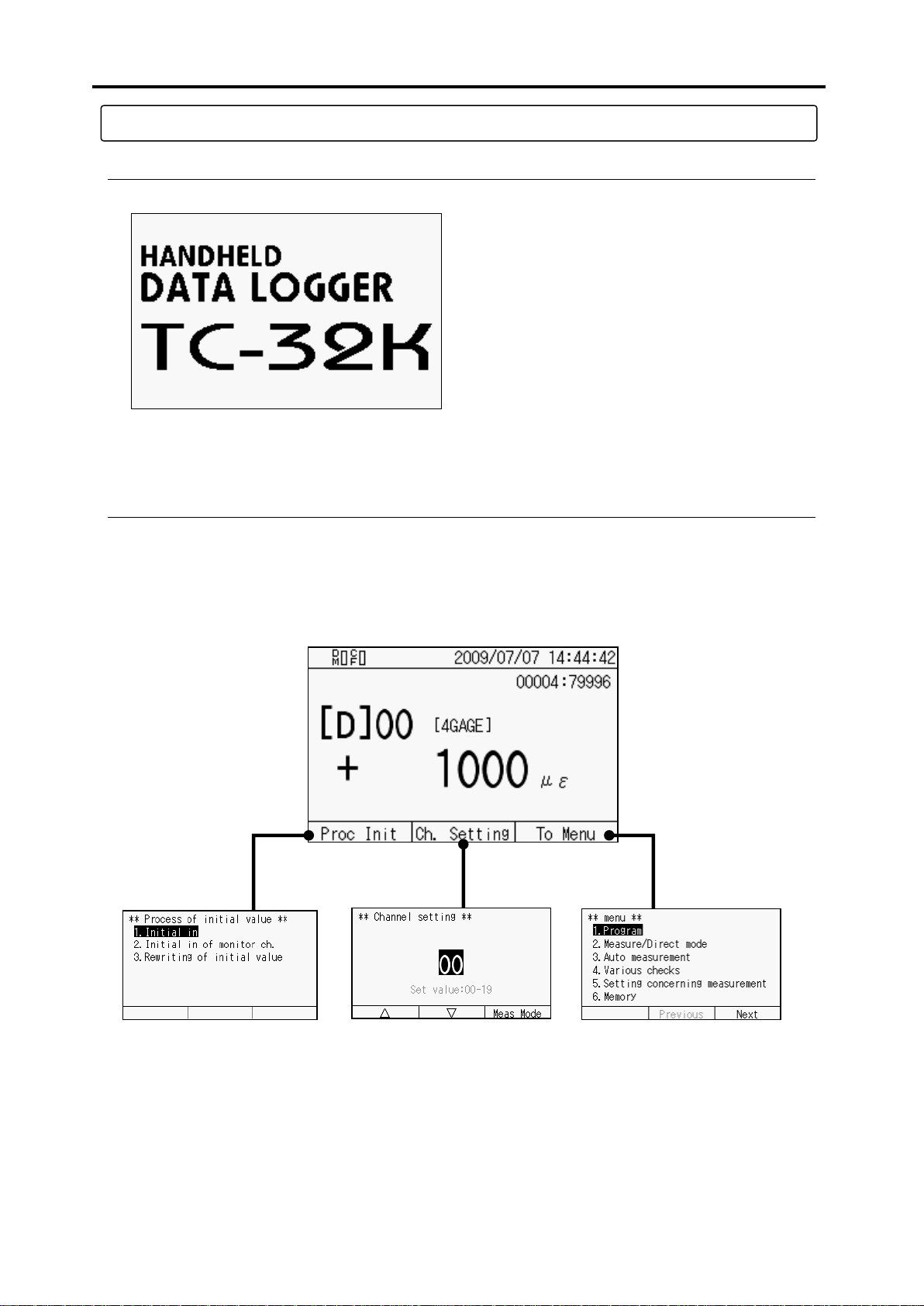
2-7
Soon after you turn on power, the startup screen
shown in the left appears. Then, the monitor
screen shown below appears.
Monitor screen
▪ Display measurement
values
▪ Main screen
Process of Initial value
▪ Initial-in
▪ Initial-in of monitor channel
▪ Rewriting of initial value
Channel setting
▪ Select measurement
channel
▪ Select measurement
mode
Menu
▪ Set program
▪ Change between Measure/Direct
▪ Set auto measurement
▪ Various checking
▪ Set measurement related items
▪ Memory, etc.
2.4 Screen outline
■ Startup screen
■ Screen configuration
2.4 Screen outline
You can move to the setting screen for functions and measurement operations from the monitor screen that
appears after startup. The illustration below shows the outline of the screen configuration:
The basic operations are: to check values or status on the monitor screen; to select “To Menu” to go to
other setting screens; and to change settings.

2.5 Operation outline
2-8
Monitor screen
Process of Initial value
Initial-in
Initial-in of monitor channel
Rewriting of initial value
Channel setting
Measurement mode switching
CSW-5B setting
(only in multi-channel mode)
Monitor type selection
Menu
Program setting
Sensor mode
Coefficient , Display digit, Unit
Coefficient
Display digit
Unit
Cap/R.O. setting
Coefficient setting check
RJC for thermocouple
Reading of TEDS sensor
Measurement mode switching
Measure/Direct switching
Auto measurement setting
Interval measurement setting
Interval measurement Start/Stop
Various checks
Insulation check
Resistance check
Dispersion check
Lead wire resistance check
Bridge output check
Coefficient setting check
Settings for measurement
Simple measure
Comet
Power frequency
Initial-in permission
Burn out check
Menu
Memory
Data memory
File dump
Data memory setting
Data number setting
Ring buffer setting
Deletion of data memory
Printout of data memory
CF card
File dump
File name and format setting
Deletion of files
Saving data files
Reading the saved files
CF card formatting
Copying the file
Record on data memory, CF card
Interface setting
RS-232C setting
Baud rate
Data bit
Parity
Stop bit
Flow control
Timeout
Data output destination setting
Data output format setting
Data format
Presence of header
Presence of time data
Settings for external display
Baud rate
Parity
Other settings
Auto power off
Version information
Date and clock
Display language
Maintenance
LCD backlight
LCD brightness
Contrast
Alarm sound volume
Upgrading
Factory setting
2.5 Operation outline
From the monitor screen, you can move to various modes with three function keys. This section explains
these function keys and systems, and the keys used for operation and their functions.
■ Operation system
The operation system of TC-32K is shown below:
2.5 Operation outline
2-9
Operation key
Main function
F1
Transfers to “Initial value processing”.
F2
Transfers to “Channel setting”, Changes pages.
F3
Transfers to “Menu”, Changes pages.
▴▾◂▸
Move the cursor, Select monitor channel, Increase/decrease values
0 ~ 9
Input values, Select items on Menu
ENT/START
Fixes setting, Starts scanning measurement
ESC/KEY-LOCK
Cancels setting, Moves to higher Menu layer, Lock/release the key
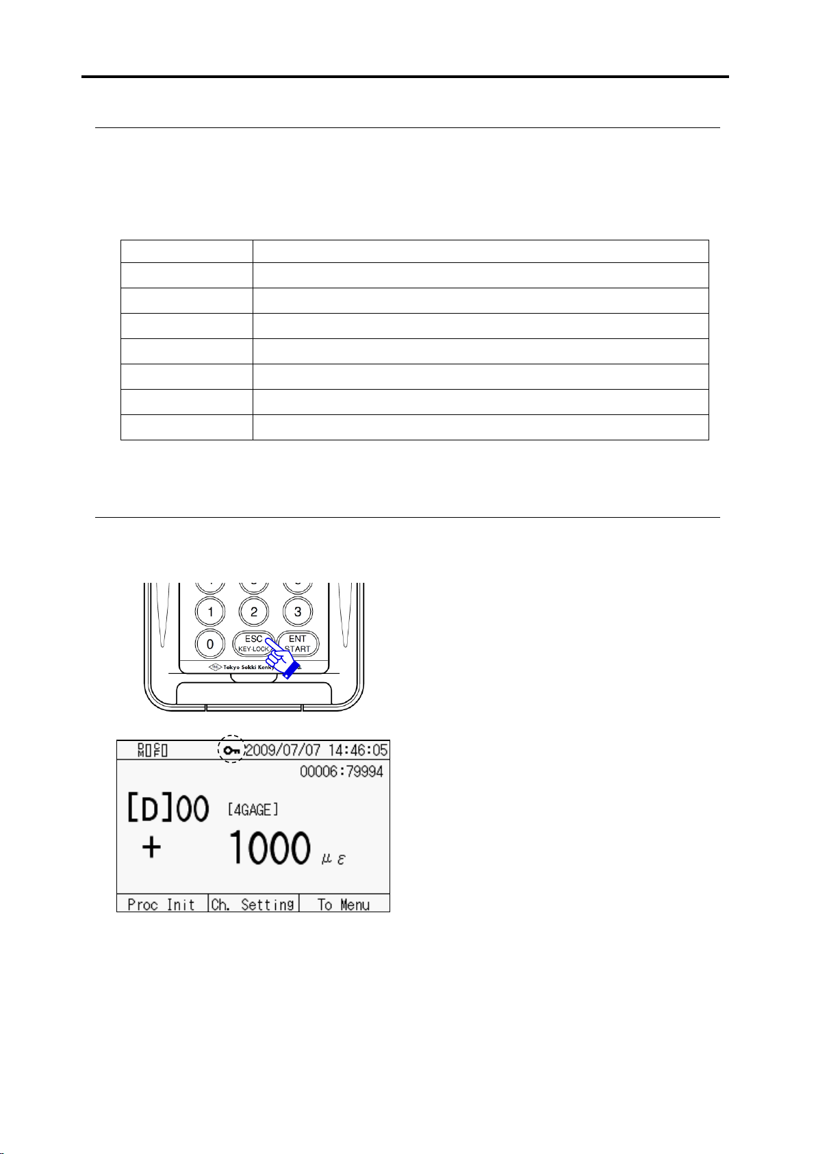
Activate key lock
Press the [ESC/KEY-LOCK] key for 3
seconds or more, and the key lock function
becomes active after the buzzer sound. The
mark showing key lock appears on the
screen.
Release key lock
Press the [ESC/KEY-LOCK] key for 3
seconds or more, and the key lock function
becomes inactive after the buzzer sound.
注意
■ Key switch
Commencing with operation to move to Menu, you can operate the TC-32K with the key switches located
on the front to switch the screens, input values, start measurement, and perform checking.
This document describes key switches to be operated, as “Select [F3]”, to explain the procedures. The
functions of each key are shown below:
■ Key lock
The key lock function prevents careless operations or setting changes. However, the [ENT/START] key
and the [POWER] key are effective even during the key lock function is active.

2.5 Operation outline
2-10
✎memo

Chapter 3
Sensor Connection
3.1 Sensor connection ····································· 3 - 2
3.1 Sensor connection
3-2
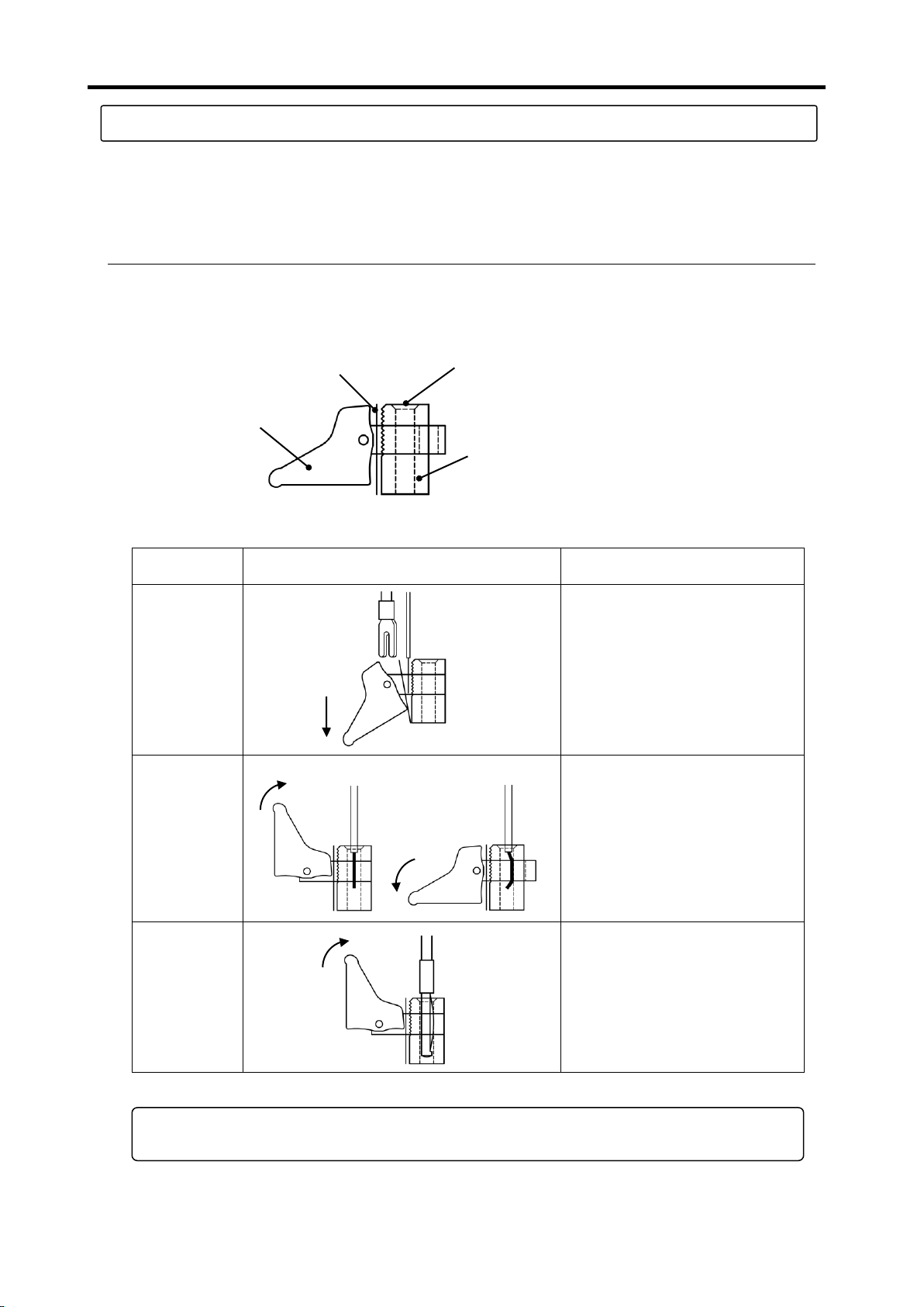
Connected
wire
Lever operation
Details
Extremely
thin lead wire
Arrow type
crimp
terminal
Take down the lever forward.
Insert the conductor part of lead
wire or the arrowhead of crimp
terminal between the terminal
block and the plate spring, and
place back the lever.
Lead wire
Take down the lever backward.
Put the lead wire through the slot
and place back the lever (if the
lead wire is extremely thin, it may
be broken).
Banana plug
Take down the lever backward,
and insert the banana plug into
the terminal slot (no need to
place back the lever).
Lever
Plate spring
Slot
Terminal
block
Take
down
Take down
Place
back
Take down
When the lever hardly moves, wipe off powder and dust with alcohol, and grease it up
with silicon grease or molybdenum mixed grease for automobiles.
Note
3.1 Sensor connection
Two ways of connection are available; with the one-touch terminal block, or with the NDIS connector.
The one-touch terminal block system is applied to sensor cables without connector, and also applicable to a
wide range of cables including thin wires, and wires with crimp terminals or banana plugs.
■ How to use input terminal block
This section explains part names of input terminal block, applicable lead wires and wire end shapes, and
lever operation of the terminal block.
○ Part name
○ Wire connection
3.1 Sensor connection
3-3
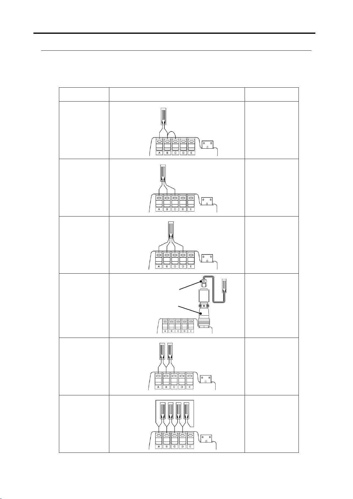
Measurement
object
Wire connection diagram
Sensor mode
Quarter bridge
2-wire
1G3W 120Ω
1G3W 240Ω
1G3W 350Ω
Quarter bridge
3-wire
1G3W 120Ω
1G3W 240Ω
1G3W 350Ω
1-gauge 4-wire
1G4W 120Ω
1G4W 240Ω
1G4W 350Ω
1-gauge 4-wire
conversion
adapter
(optional item)
1G4W 120Ω
1G4W 240Ω
1G4W 350Ω
Half bridge
2GAGE
Full bridge
4GAGE
4G C350Ω
4G 0-2V
Modular connector
1-gauage 4-wire
Short between B and C
with lead wire
■ Wire connection by sensor type
Wire connection procedure varies according to type of the sensor to be measured. The table below shows
the connection procedure and the proper sensor mode for each sensor.
○ Wire connection table
3.1 Sensor connection
3-4
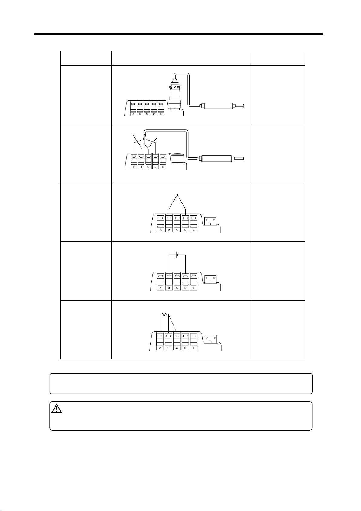
Measurement
object
Wire connection diagram
Sensor mode
Transducer
with NDIS
connector plug
4GAGE
4G C350Ω
4G 0-2V
Transducer
without
connector
4GAGE
4G C350Ω
4G 0-2V
Thermocouple
temperature
measurement
Thermocouple
T, K, J, B
S, R, E, N
Direct current
voltage
measurement
DC voltage
300mV
DC voltage 30V
DC AUTO
(up to 30V)
Pt-RTD
(Platinum
resistance
temperature
detector)
Pt100 3W
Red
Green
Black
White
+ For most of our transducers
You cannot use a calibrator or an equivalent, which has the input connector F and G
connected for remote sensing.
Note
Lead wire color of transducer may be different from the above diagram depending on
the transducer type and manufacturer. Please read the transducer’s operation
manual carefully.
Warning

Chapter 4
Monitor Display and Measurement
4.1 Monitor screen outline ························· 4 - 2
4.2 Monitor display ·································· 4 - 2
4.3 Initial value processing ························ 4 - 5
4.4 Channel setting ·································· 4 - 8
4.5 Record of measurement values ············ 4 -10
4.6 Sub LCD ·········································· 4 -11

4.1 Monitor screen outline
4-2
Monitor space
(Displays monitored
values)
[Proc Init]
(Transfers to the screen to
process initial values)
[Ch. Setting]
(Sets a channel to be monitored)
[To Menu]
(Transfers to the Menu screen)
Date and time
Saving in data memory
Remaining capacity of
battery (As the capacity
gets lower, the lighted area
becomes smaller.)
Function keys
D: Direct
M: Measure
m: Measure (Comet)
J: Jump
Measurement object (when “Simple measure” is selected)
Sensor mode
Measurement value
(monitored value)
Unit
Saving in CF card
Key lock
Simple measure
Communicating with USB
Communicating with RS-232C
4.1 Monitor screen outline
After power-on, the monitor screen appears on the display. This screen displays measurement
values (monitored values), time, status, and other information. You can change the screen to set
other various functions using key switches.
4.2 Monitor display
With the monitor display function, measurement values that the instrument is monitoring are
displayed on the screen all the time. Displayed data varies according to the monitor display
system that has been selected in advance.
Three display methods are selectable, which are value monitor, waveform monitor and monitor
off. For the value monitor, it is selected between 1-channel and 5-channel with dedicated
switching box connected (when multi-channel mode is selected).
The following sections show the examples of the monitor screen and explain items on each
screen.
■ Value monitor
The screen displays measurement values of the selected channel. The number of channels that can
be displayed on the screen is up to five (when multi-channel mode is selected).
○ Example of 1-channel display (single channel mode)
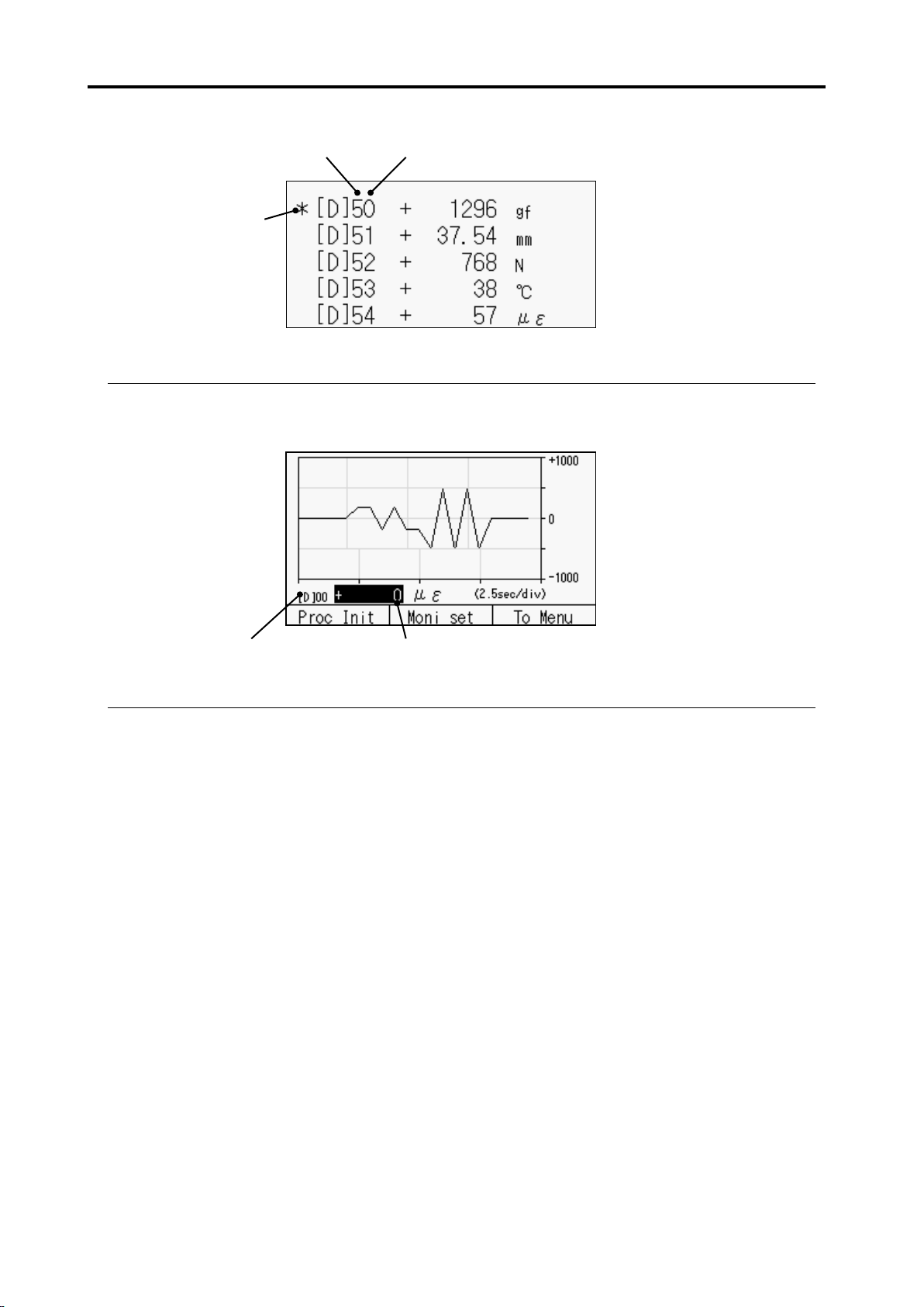
4.2 Monitor display
4-3
Box number
CSW-5B channel
Mark showing that
the channel is
monitored
Measurement value
(monitored value)
Monitored channel
○ Example of 5-channel display (multi-channel mode)
■ Waveform monitor
The screen displays a line chart showing variation of measurement value with time. The number
of channel that can be displayed in the waveform monitor is one.
■ Meaning of displayed value
When the sensor is connected to the input terminal and the sensor and the measurement system
have no problem, a certain value is always displayed. However, if the sensor is not connected,
or connected but its wire is broken, or the input value is over the measurement range defined in
the specifications, the following indications are displayed to alert, instead of measurement values.
The indication that appears when a problem occurs, and supposed cause are shown below:
[ * * * * * * * ] Open data
The sensor is not connected, or the sensor cable is broken.
[ + * * * * * * * ] +Over data
The input value is over the measurement range in the + direction.
[ - * * * * * * * ] -Over data
The input value is over the measurement range in the - direction.
[ * * * * I * * * ] Initial value over data
The initial value (initial unbalanced value) is over the initial value storing range.
[ ! ! ! ! ! ! ! ] Indication digits over
The indication digits (before the decimal point) are insufficient for displaying the
measurement value.
[――JUMP――] Jump
This message is displayed when the sensor mode is “JUMP”.
4.2 Monitor display
4-4
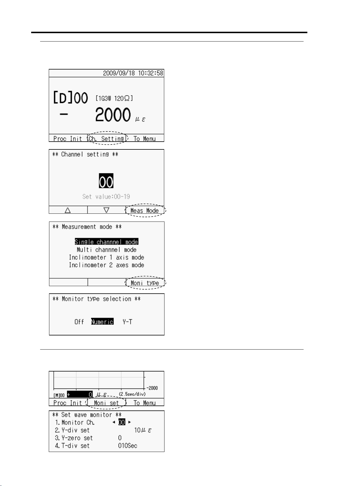
1) Press [F2] key to go to “Channel setting”
from the monitor screen.
2) The channel setting screen appears. Press
[F3] key to go to “Measurement mode”
switching screen.
3) Press [F3] key to go to “Monitor type”
selection screen.
4) With [◄][►] keys, move to either “Off
(Monitor Off)”, “Numeric (Value
monitor)”, or “Y-T (Waveform monitor)”
and press [ENT] key.
Setting the waveform monitor
Press [F2] key to go to “Monitor setting”
screen from the monitor screen, and the left
screen appears. With [◄][►] keys, change
the set values of each item.
Monitor channel: 0 ~ 19
Y-axis setting: Variable according to display
digit setting
Y-axis zero setting: 0, 1, 2, 3 or 4
T-axis setting: 10 ~ 100 seconds
■ Monitor type selection
Select the display format of monitored value among value monitor, waveform monitor, and OFF.
When you select “Monitor OFF”, the TC-32K does not supply bridge excitation to the sensor and
does not display monitored value on the screen (it does not measure).
■ Waveform monitor setting
When waveform monitor is selected, its conditions are set. The number of channel is one for the
waveform monitor.
 Loading...