

Tokyo Keiso M-900 series Technical Guidance
■ OUTLINE
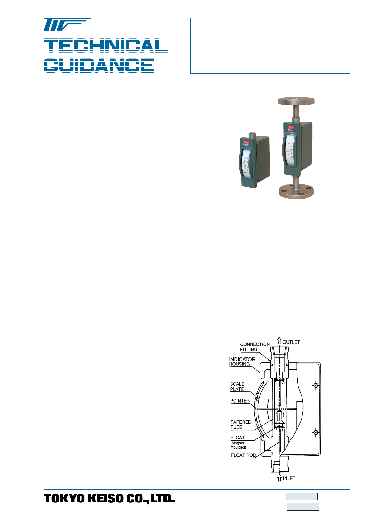
M-900 series MICRO FLOWMETER is a metal tube
variable area flowmeter for small flow measurement.
All metallic construction covers even high temperature
and high pressure applications.
Thanks to compact design, M-900 is suitable for
assembling onto various devices. It also covers small
sized industrial processes.
M-900 series MICRO FLOWMETER has been used
for nuclear power plants for long time and HPGSL
certified version is also available.
In addition to local indication, various versions including
pneumatic, electric and alarm output types are ready
to meet your requirements of remote monitoring and
control.
■ FEATURES
1. Compact design
Small and light design offers easy installation onto
panels as well as process pipings.
2. High sensitivity
The pivot bearing and light weight pointer enable
to follow float movement swiftly.
3. Suitable for corrosive and opaque fluids
Anti-corrosive materials such as titanium and
MA276 are available to meet your specifications.
For assembling onto devices, test plants and general
industrial processes
M-900 Series
MICRO FLOWMETER
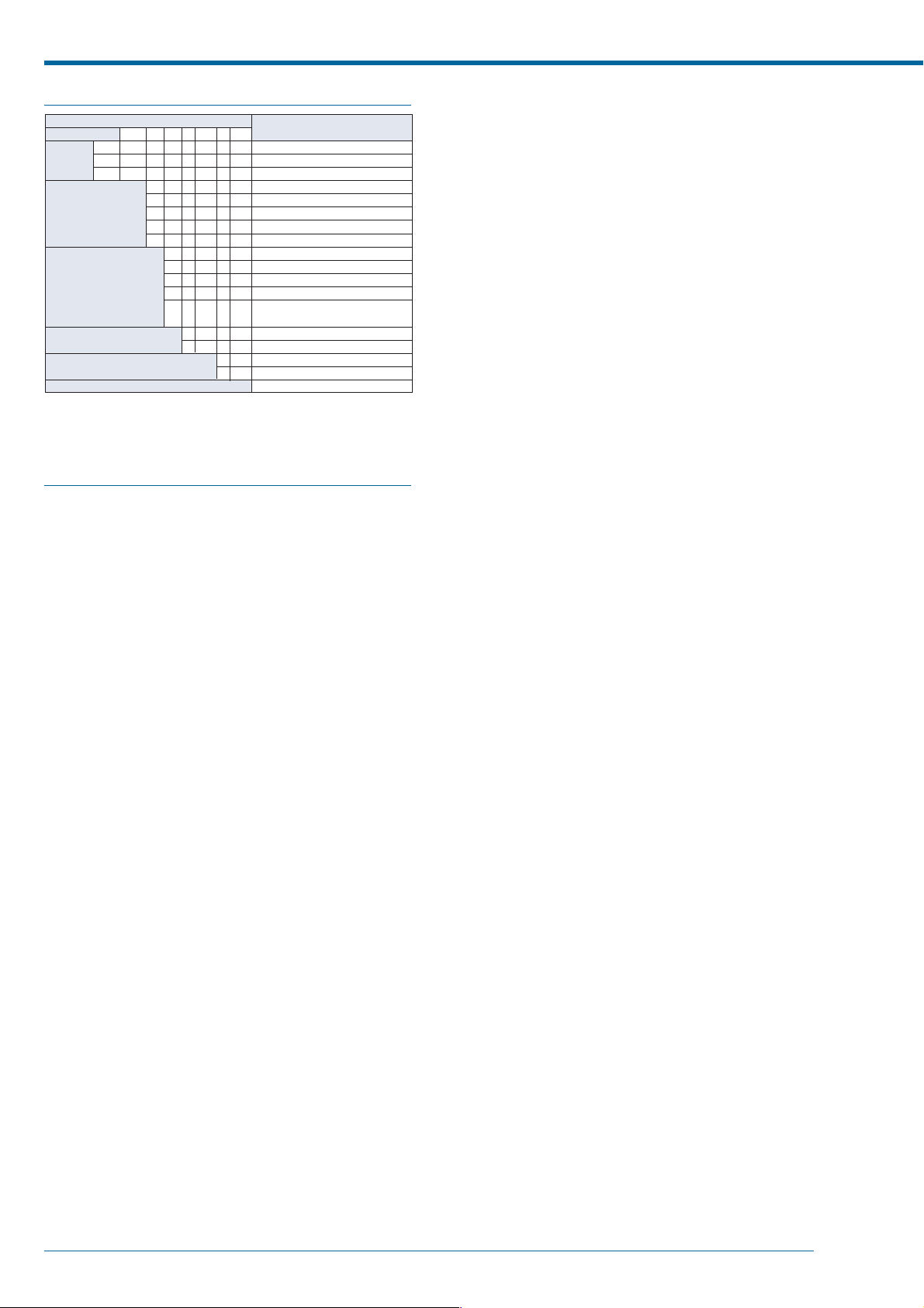
■ OPERATING PRINCIPLE
The flow path has a tapered part. A float in which a
magnet is moulded is located in the tapered tube. The
fluid is introduced from the bottom end of flowmeter
and goes through the tube upward.
Because of the differential pressure produced by the
float and tapered tube, the float is pushed upward and
stops at a position where the weight of float and the
differential pressure balance. Thus, the position of float
corresponds to the flow rate. The moulded magnet in
the float attracts the pointer, and the pointer indicates
the flow rate on the scale plate.
The inside of the tube and indication mechanism are
totally isolated by magnetic coupling.
4. Easy reading of scale and pointer
The long pointer and wide linearized scale plate
make your reading easier.
5. Supporting devices
Various supporting devices to meet your requirements
are available such as flow control needle valve,
strainer and constant flow valve.
TG-F285-2E JAN. 2007K
TG-F285-8E MAY. 2014K
M-900 Series MICRO FLOWMETER
■ MODEL CODE
MODEL CODE
M–9
Construction
Function
Flow direction
Additional function 1
Additional function 2
Special
*1 Flameproof type is applied only for electric transmission type EP-M-92첸.
*2 Intrinsically safe type is applied only for alarm output type IS-M-95첸.
*3 Liquid damper can be provided on the flowmeters with Bottom side
EP–
IS –
and Bottom rear
→Top rear connections only.
–
–
Dust-proof and weatherproof
Flameproof *
0
1
2
5
6
1
2
3
4
5
–
D
–
DU
Intrinsically safe *
Local indication
Pneumatic transmission
Electric transmission
Alarm output with reed switch
Alarm output with photo electric switch
Bottom to Top
Bottom to Top side
Bottom side to Top side
Bottom side to Top
Bottom rear to Top rear (only available for local indicator type)
With liquid damper *
With gas damper
–
Needle valve at outlet
VU
–
Needle valve at inlet
VL
/Z
Contents
1
2
3
→첸
■ ADITIONAL FUNCTION
1. Liquid damper Model M-9첸첸-D
A damper mechanism is required for gas and steam
measurement especially at low pressure service to
prevent float hunting.
The damper installed at the bottom of flowmeter
ensures the accuracy and durability of flowmeter.
The damping mechanism works to reduce the
abrupt movement of float utilizing the resistance
generated between oil in the damper and damping
element connected to float rod.
The damper is recommended also for the liquid
service having a pulsation flow.
is applicable because of the ingress into the piston
and cylinder which might lead to the malfunctioning
of the flowmeter.
3. Needle valve M-9첸첸-V첸
A needle valve used for flow rate control is
recommended at the downstream of flowmeter to
avoid hunting for gas measurement.
On the other hand, for liquid measurement the
pulsation may be eased by the valve located
upstream.
4. Magnet strainer. See clause "Accessories" at the
following page.
The iron particles contained in fluids may cause
the malfunctioning of flowmeter due to the attracted
irons on the moulded magnet in the float. The
particles can be eliminated with the magnet strainer
at the inlet of the flowmeter. For this purpose
dedicated strainer with 100 mesh (optionally 200
mesh) is available.
5. Purge set. See clause "Accessories" at the
following page.
Purge set of M-900 micro flowmeter and constant
flow valve keeps constant flow rate even supply
pressure or down stream pressure is fluctuated.
2. Gas damper Model M-9첸첸-DU
The gas damper which requires no damper liquid
is available for gas measurement. A mechanical
damper consists of a cylinder and a piston
connected with float rod. This type needs no space
for damping mechanism at the bottom of flowmeter.
Therefore, this damper is applied for any direction
type of flowmeters which result in the flexibility of
piping design. Furthermore unnecessary re-filling
of damper liquid improves the maintenability.
The gas damper is effective for the low pressure
gas services which cause hunting of indication and
for the services which does not permit damping
liquids. It is highly recommended to have gas
damper for the services less than 0.3MPa pressure
and without needle valve at the downstream.
However, this type is applicable only for dry gas
services and not applicable for liquids nor
condensable vapors. Neither chlorine gas which is
synthesized easily with other chemicals nor gases
containing foreign materials like rust, dust and oil
2TOKYO KEISO CO., LTD. TG-F285-8E
■ ACCESSORIES
NEEDLE VALVES
Needle valve for flow adjustment. It will be assembled onto flowmeter
● STANDARD SPECIFICATION
Nominal size Rc3/8
Fluid pressure Max. 3 MPa
Fluid temperature –15 to +150°C
Material SUS316/PTFE
High pressure versions are available on request.
Consult factory for details
M-900 Series MICRO FLOWMETER
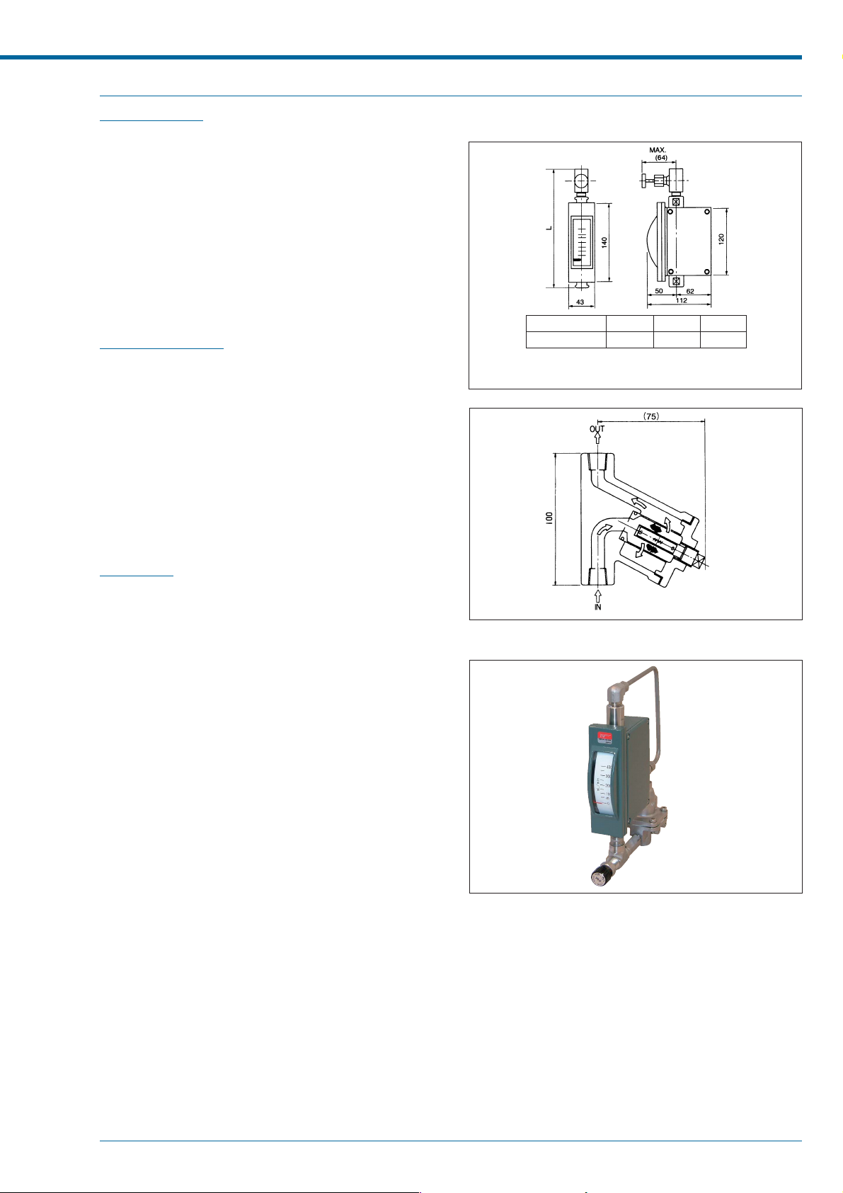
● External dimension of M-901-V (With valve)
Standard type
MAGNET STRAINER
A magnet strainer will be assembled into the flowmeter before deliv-
ery on request.
● STANDARD SPECIFICATION
Nominal size 1/4”, 3/8”, 1/2”
Fluid pressure Max. 1.5MPa
Fluid temperature Max. 200°C
Filter Std. 100 mesh
(200 mesh as option)
Material SUS304, SUS316
PURGE SET
Separate TECHNICAL GUIDANCE of "C" Series is available on re-
quest for this version.
Thread size
L (mm
* Screw socket (s) provided for Rc1/4 and Rc 1/2.
* "L" length of the flowmeter with gas damper is
extended by 40mm at downstream.
Rc1/4
)
245
Rc3/8
225
● External dimension of MAGNET STRAINER
Rc1/2
275
● CM-21-900 TYPE PURGE SET
TOKYO KEISO CO., LTD. 3TG-F285-8E
 Loading...