

Tokyo Hy-Power HL-350VDX User Manual
User’s Manual
144MHz Band
330W Power Amplifier
Model HL-350VDX
TOKYO HY-POWER LABS., INC.

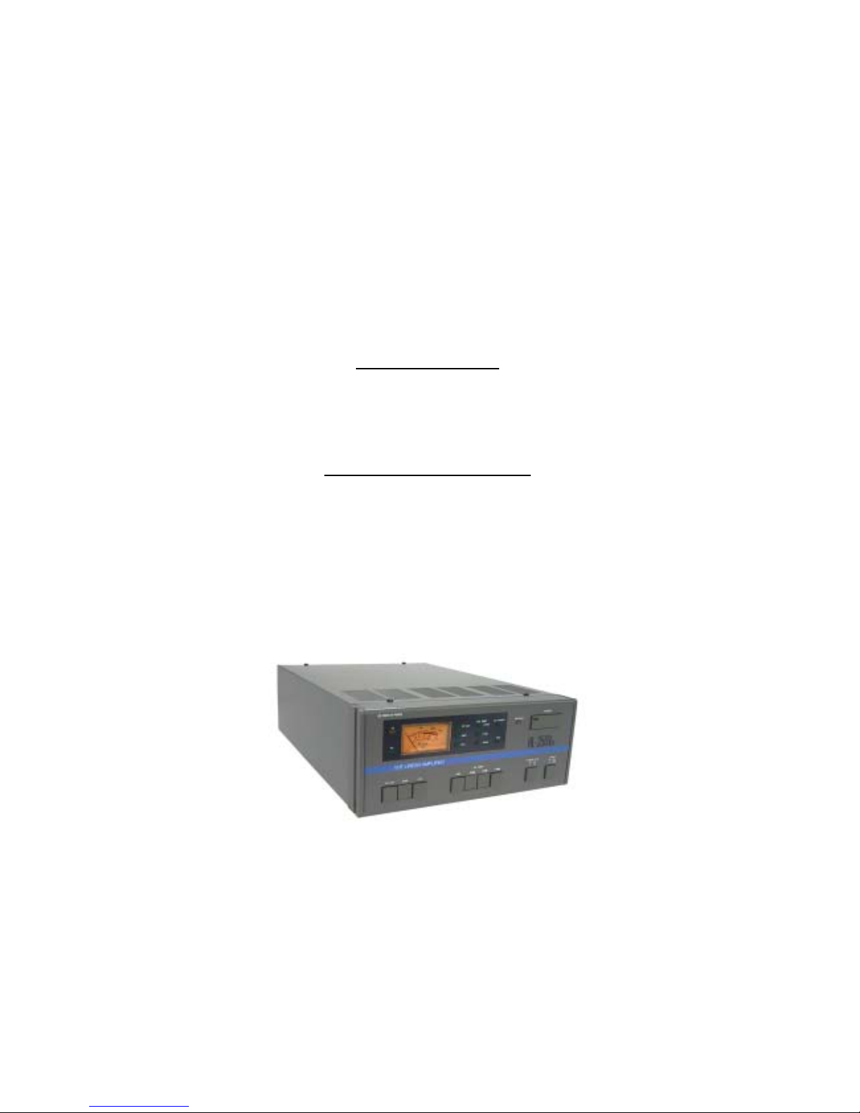
Introduction
The HL-350VDX is a 144MHz Band Linear Power Amplifier with the maximum
output power of 300W (nominal, 330W max.), designed with Tokyo Hy-Power’s
accumulated VHF technologies. This is a completely solid-state amplifier
capable of handling all transmission modes. There are built in such new
functions as an automatic VSWR meter, a new type DC-operated line-flow fan
and a GaAs FET RX Pre-amp with a selectable RX gain.
Main Features
1. Easy to Operate/ Functional Design:
By combining a small heat-sink with a powerful DC-operated line-flow fan,
the HL-350VDX is made light in weight.
It has a fashionable design by putting the heat-sink inside the cabinet.
2. Adoption of Multi-Protections:
It incorporates five kinds of protection circuits developed by our own
advanced technologies. This sophisticated protection gives you a
warning(shut-down) before getting into any trouble.
3. Multi-Metering Method:
The switch selected analog multi-meter on the front panel reads RF OUT (TX
output power), AUTO SWR (standing wave ratio, automatically measured), or
VCC (power supply line voltage), enabling the operation to be comfortably
done at all times.
The high-performance power meter is of a directional coupler type, giving
quite accurate readings.
4. Low-Noise RX Pre-Amp:
It incorporates a low-noise RX pre-amp utilizing a performance-proven GaAs
FET.
The gain of the pre-amp can be selected depending on the receiving
condition. More cozy VHF communication can be enjoyed with the
HL-350VDX.
5. Auxiliary Remote Controlling Function:
A jack for the connection with a remote controller (optional HRC-60) is
provided on the rear panel.
Remote controlling of the power supply, the RX pre-amp and so forth can be
controlled in the remote location.
1
Specifications
Frequency Band : 144MHz Band (available for 144-148 MHz)
Mode: FM, SSB and CW
RF Output Power: 300W nominal (330W max.)
RF Input Power: 10/25/50 W (manually selectable)
DC Power Supply: 13.8 VDC
Power Consumption: 42A max. (at 250W output)
Input/Output Impedance: 50Ω
Input/Output Connectors: N-type
Spurious Signal Level: -60dB or less
RX Pre-Amp Gain: -20dB, +6dB, +15dB (selectable)
Accessories:
① RF Output Meter/ Automatic VSWR Meter
② Low-Noise GaAs FET RX Pre-Amp
③ Warning Protection Circuit
(protections for overvoltage, overdrive and
mis-match)
④ Two-Speed Line Flow Cooling Fan
⑤ Reverse DC Power Polarity Protection
Fuses: 20A x2, 1A x1
Attachments:
① Power Supply Cable 8sqmm, 2m long:
red x1, black x1
② ACC 8-Pin DIN Plug x1
③ Jumper Cable with N-M connectors:
69cm long x1
④ Spare Fuses: 20A x2, 1A x1
Dimensions & Weight 9.6(W) x 3.9(H) x 14(D) inches, Approx. 12.5 lbs.
245(W) x 100(H) x 355(D) mm, Approx. 5.5kg
2
Explanation of Features
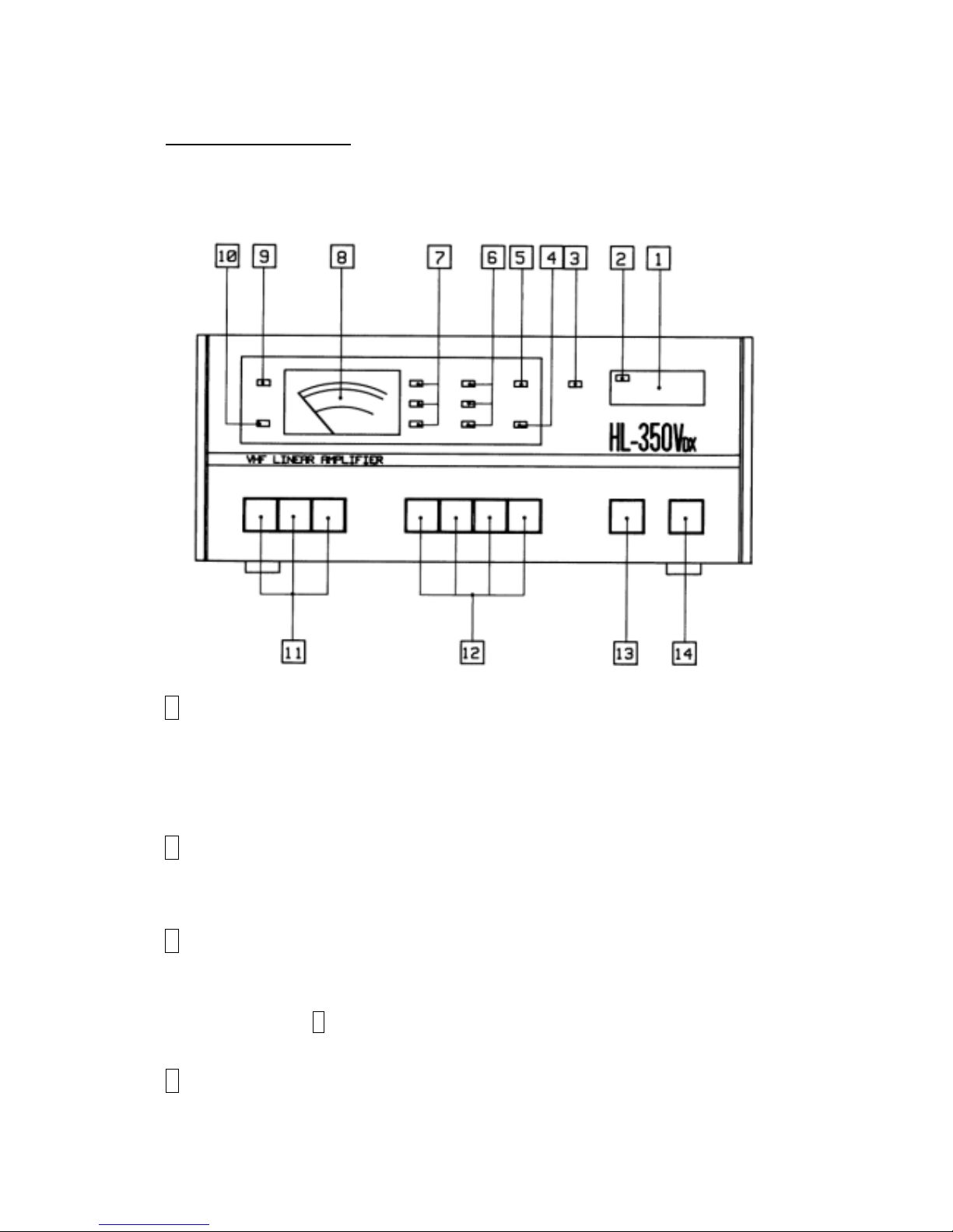
<FRONT PANEL>
1 POWER (MAIN DC POWER SUPPLY SWITCH):
A power switch for the TX amp unit. With the first push, the switch will be locked,
turning the power ON. With the second push, the knob will be released to turn
the power OFF.
2 POWER (LED):
Lights when the POWER of TX RF amp unit is turned ON.
3 WARNING (LED):
Lights when the power supply to the TX Amp unit is shut down due to overdrive,
overvoltage or mismatch of antenna VSWR etc. After the possible cause of shut
down is corrected, 1 POWER SWITCH may be turned ON again to reset.
4 FAN (LED):
Turns ON when the temperature of the heat sink exceeds 50℃. Then, the fan
3

starts to run at its full speed. When the heat sink temperature exceeds 70℃ due
to a long continuous transmission or any other reasons, the built-in
thermo-sensor will halt the transmission automatically. In that case, do not turn
OFF 1 POWER SWITCH. This is because the fan has to be kept running in
order to cool down the heat sink. Keep 1 POWER SWITCH ON. Transmission
can be restarted once the heat sink temperature is cooled down to the normal
range.
5 LO POWER (LED):
Lights when the TX input attenuator is turned on. With the attenuator ON, the
transmission power becomes approx. half of the full output power.
6 RX AMP +15dB/ +6dB/-20dB (LED):
Three LED’s show the approximate gain of the R pre-amp at each gain selection.
The gain can be selected by 12 RX AMP SWITCH.
7 RF OUT/SWR/VCC (LED):
Indicates the scale of the multi-meter being selected.
8 W/SWR/VCC METER:
The multi-meter gives the readings of wattage (RF output power), SWR
(standing wave ratio), and Vcc (DC power supply voltage) respectively. The
output power shown is average power. In the SSB operation, the output power
indicated in the meter can only be approx. 40% of the peak power output. SWR
is automatically shown at any power above 50W as a result of the incorporation
of advanced IC.
9 TX (LED):
Lights when the amp is in transmission mode. The LED goes OFF when in the
receive (RX) mode.
10 RX (LED):
Lights when the RX pre-amp is turned ON.
11 RF OUT/SWR/VCC (METER SELECTION SWITCH):
Depending on the function to monitor, push the desired switch for the proper
4

readings.
12 RX AMP OFF/-20dB/+6dB/+15dB (SELECTION SWITCH):
Selects the gain of the RX pre-amp. Select the proper gain so that the signal can
be copied most clearly.
13 POWER LEVEL HI/LO (SELECTION SWITCH):
At 10W and 25W inputs, the power level can be switched to either HI or LO. At
the LO mode, the output power becomes approx. half the HI power. (At 50W
input, the power level cannot be switched to LO.)
14 MODE FM/SSB (SELECTION SWITCH):
Selects the changeover delay time for TX/RX transition when the operation is
made with the RF key. It takes about 1 second for TX to change to RX state.
When the switch is pressed for FM operation, TX state will instantly change to
RX. For CW, keep this switch pressed ON (SSB position) and for the packet,
keep it pressed OFF (FM position.)
5
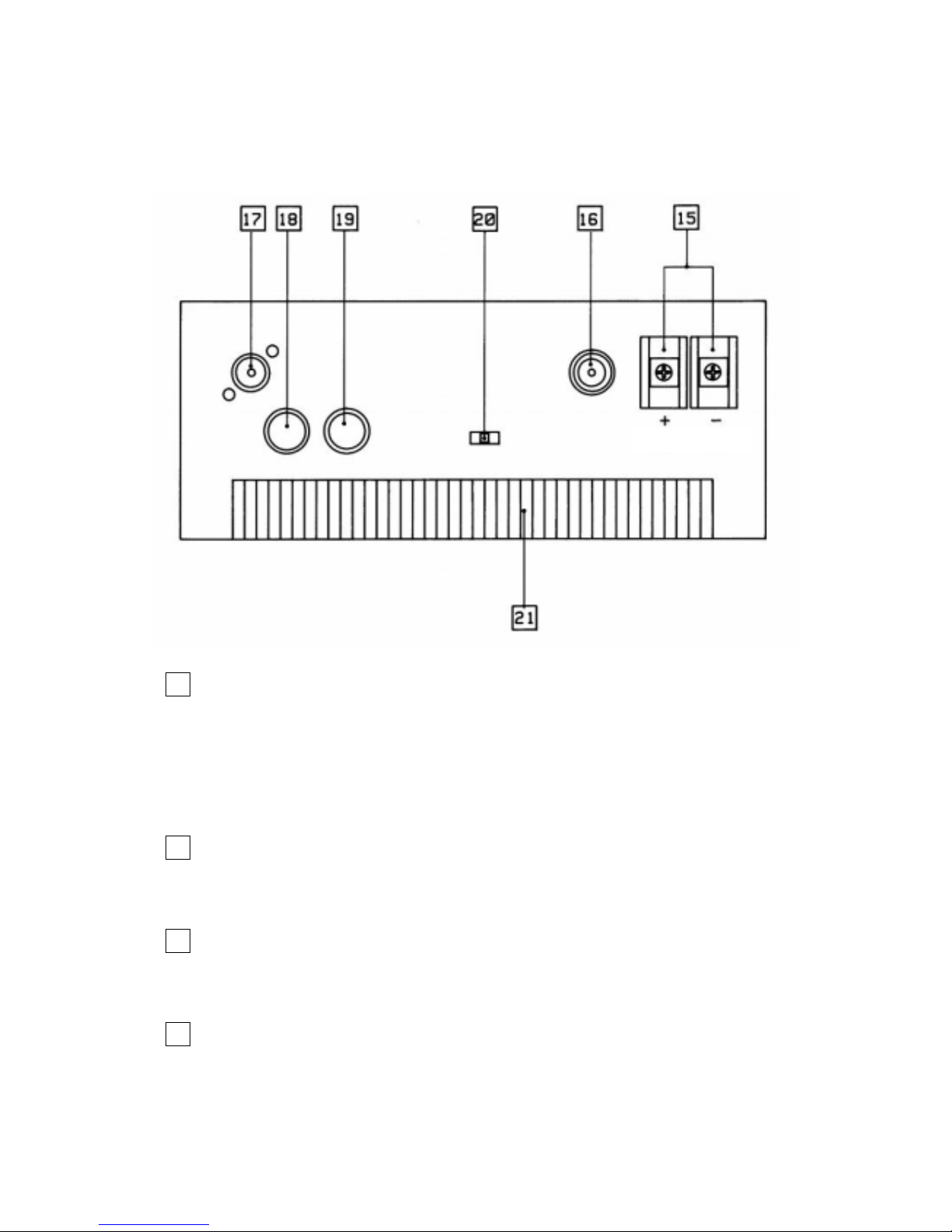
<REAR PANEL>
Red Blac k
15 13.8VDC (POWER SUPPLY TERMINAL):
Use the included power supply cable for the connection with a stabilized DC
power supply.
Connect the red wire to + and black wire to - .
Make sure to use a power supply with a capacity of 50A minimum.
16 TX (INPUT CONNECTOR, TYPE N):
Connect the coaxial cable from the transceiver.
17 ANT (OUTPUT CONNECTOR, TYPE N):
Connect the coaxial cable from the antenna.
18 ACC (EXTERNAL TX/RX SWITCHING/PTT DIN SOCKET):
Connect DIN plug of hard key control cable from the radio.
Refer to Pages 9 to 11 for pin assignments of 8 pin DIN plug.
6
 Loading...