

INSTRUCTION MANUAL
HF LINEAR POWER AMPLIFIER
MODEL : HL-2.5KFX

1. Introduction
Thank you for purchasing the HL-2.5KFX. This compact and lightweight
desktop HF linear power amplifier has a maximum input power of 2.9 kW. Our
solid-state broadband power amp technology makes it the smallest and lightest
in the industry.
Typical output power is 1.5 kW PEP/SSB with the drive power of 85-90 W. The
built-in band decoder will let you forget about the band setting when the amplifier
is connected to your modern radio through such band data cables as ICOM CI-V,
DC voltage (ICOM, Yaesu), and RS-232C (Kenwood). All the data cables are
included in your amplifier for your convenience.
2. Cautions
2-1 Unpack the amplifier, check the fan guard at the rear panel Fan to see if
there is any damage caused by the physical shock during the transportation. Fan
blades must be free to rotate when powered.
The amplifier is cooled by forced airflow. Several inches of clearance on the top
and the rear wall are necessary to allow for smooth air intake into the fan. Do not
block the air vents on the top cover.
2-2 Keep the amplifier out of direct sunlight, in a cool dry environment.
2-3 Internal high voltages, (AC, DC and RF), are present at all times, ON
AIR or OFF. Internal access should be limited to avoid injury.
2-4 Turn off the AC main power immediately upon any unusual sounds,
sights or odors. Check the multimeter readings of Vd and Id, the fuses and all
cable connections around the amplifier. Please notify the dealer or the factory of
any problems.
2-5 For your safety, do not operate the amplifier without adequate grounding.
A proper ground connection will result in peak performance and stability, in
addition to reduced RF strays or noises.
2-6 To eliminate the RF interference to such home appliances as TV, FM
radio, telephone sets, etc., it is recommended that clamp-on ferrite cores be
1

inserted at both ends of the remote control cable, ALC cable, coaxial jumper
cable, and antenna cables, as needed. Also, a common mode AC line filter (near
the AC outlet), and in-line low pass filters on the antenna coaxial cable, (as
necessary), are recommended.
2-7 The amplifier has fast acting sophisticated protection circuits controlled
by the latest microprocessor technology . Please note, however, any such actions
that cause the same fault to occur repeatedly, will lead to failure of the valuable
final power FET transistors. Also note that the full power CW (or carrier) drive
under the erroneous MANUAL BAND SET leads to the failure of the final power
FET’s (See page 11, Section 7. Connection). In this sense, it is highly
recommended that the amplifier is connected to the radio with supplied Band
Data Cable.
2-8 Before checking inside the amplifier, be sure to wait a few minutes for
the high DC voltage to discharge (monitor Vd meter reading). The internal
potentiometers for RF power detector, protection circuits, FET bias voltage
circuit, etc., are precisely adjusted at the factory, and should not be altered.
Doing so, would require readjustment with precision measuring instruments.
2-9 The primary power transformer is factory pre-wired for AC 240 V
operation. (See page6, Section 5. AC Line Voltage) Be sure to verify your AC
line voltage before you plug the AC power cord into the outlet.
2-10 Before powering on the amplifier, be sure to connect a dummy load (50
ohms, 1.5 kW min.) or a well-adjusted antenna to the output terminal. Operating
without any load will cause extreme stress to the RF power FET’s, although
protection circuits should work under critical conditions.
2-11 Required drive power is slightly less than 100 W to obtain the full 1.5 kW
output. Do not attempt to operate with excessive drive from a high power
transceiver. Transmitting high drive RF (over 100 W) into the amplifier will void
the warranty.
2-12 Keep the aluminum heat sink and air openings free from dust and
blockages. Periodic cleaning will prevent degraded cooling efficiency.
2

2-13 For long continuous operation in RTTY/FM modes, it is recommended
you reduce the RF drive levels by 20% to 30% lower output than CW/SSB
modes.
2-14 To prevent damage to the precision electronic components, avoid
extreme physical shock to the amplifier. If factory service is required, the
amplifier MUST be shipped using the original box and packaging materials.
3. Features
3-1 Our solid-state broadband design engineers worked to make the
HL-2.5KFX, the lightest and most compact 1.5 kW HF amplifier in the industry.
This world-class compact 1.5 kW HF amplifier is the easiest to handle and
operate.
3-2 The amplifier is equipped with a newly developed band decoder. The
amplifier’s decoder changes bands automatically as the data signal is received
from the associated HF transceiver’s frequency bands.
3-3 The amplifier’s main PA section includes 2 high power MOS FET
ARF1500’s by Microsemi, resulting in 1.5 kW PEP (SSB max.). The amplifier’s
broadband characteristics require no further tuning once the operating band is
selected.
3-4 The amplifier allows operation in full break-in CW mode due to the use of
the amplifier’s high- speed antenna relays (made by Panasonic/Matsushita).
3-5 With the unique duct structure design and the powerful blower fan, the
aluminum heat sink block for RF PA module (and other components), are
effectively cooled. The fan’s quiet operation allows for even the weakest DX
signals to be heard.
3-6 The amp utilizes an advanced 16 bit MPU (microprocessor) to run the
various high speed protection circuits such as overdrive, high antenna SWR, DC
overvoltage, band miss-set etc.
3

3-7 This amplifier is compatible with AC 220 V and 240 V (200/230/250 V
included). See the illustration in Section 5. AC Line Voltage for changing primary
wiring of the power transformer.
3-8 For the safety of the operator, an Interlock system is employed. The AC
power is shut down if the top cover is removed, and the automated safety
interlock is activated.
3-9 An analog multimeter allows the operator to monitor Pr (Reflected
power), Vd (Drain voltage of power FET), Id (Drain current) and ALC voltage.
3-10 For future expansion, the amplifier rear panel is equipped with a control
cable connection socket, this is for the upcoming model HC-1.5KAT, auto
antenna tuner by Tokyo Hy-Power Labs. in 2007.
4

4. Specifications
Frequency : 1.8 ~ 28 MHz all amateur bands including WARC
bands
Mode : SSB, CW, RTTY
RF Drive : 85W typ. (100W max.)
Output Power : 1.5 kW PEP/CW (typ.)
(1.2 kW on 28 MHz band)
Matching Transceivers for Auto Band Decoder :
Most ICOM, Yaesu, Kenwood
Drain Voltage : 120 V (when no RF drive)
Drain Current : 30 A max.
Input Impedance : 50Ω (unbalanced)
Output Impedance : 50Ω (unbalanced)
Final Transistor : ARF1500 x 2 (MOS FET by Microsemi)
Circuit : Class AB push-pull
Cooling Method : Forced Air Cooling
MPU : PIC 18F452-I/P
Multi-Meter : Output Power Pf 2.5 kW
Reflected Power Pr 250W
Drain Voltage Vd 150V
Drain Current Id 40A
Input/Output Connectors : UHF SO-239 with low loss Teflon insulator
AC Power : AC 240 V (200/220/230/250 V) 15A max.
AC Consumption : 3 kVA max. when TX
Dimension : 325 x 145 x 405 mm (W x H x D)
12.3 x 5.7 x 15.9 inches
Weight : Approx. 25 kgs. or 57.3 lbs.
Accessories : AC Power Cord x 1
RCA Plug (Stereo Type Pair Cable) x 2
Band Decoder Cable x 3
Spare Fuse 16 A
(for AC 230V line and Internal VDD) x 4
Spare Fuse 1.6 A
(Miniature Fuse for RF Absolute Over-drive) x 3
Spare Fuse 2.0 A
(Miniature Fuse for +/- 12V Supply) x 2
5
Instruction Manual x 1
Optional Items : Auto Antenna Tuner (HC-1.5KAT)
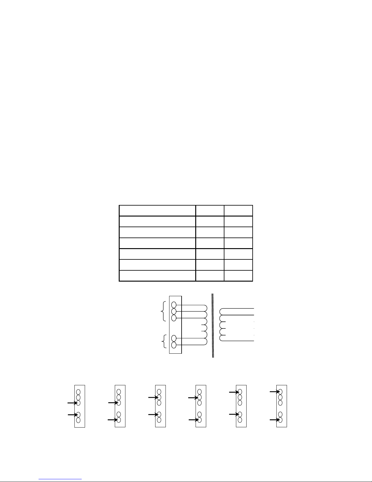
5. AC Line Voltage
5-1 The amplifier is designed to work with AC 240 V (200- 250 V).
5-2 The correct AC plug (not included in the package), must be obtained
locally due to the AC plug variations worldwide.
5-3 The AC voltage has been factory preset for 240 V use (or as requested
by the customer at the time of order). See the other illustration for AC voltages
other than 240 V. For your safety, before making these adjustments, be sure to
pull the AC plug from the AC outlet to avoid injury.
AC Line Tap 1 Tap 2
200V (195V-205V) 0 V 200 V
210V (205V-215V) -10 V 200 V
220V (215V-225V) 0 V 220 V
230V (225V-235V) -10 V 220 V
240V (235V-245V) 0 V 240 V
250V (245V-255V) -10 V 240 V
Guide for Tap Selection
240V
220V
200V
A
C-N Tap 1
-10V
AC-L Tap 2
TAP CONSTRUCTION
0V
Secondary
Winding
240V 240V 240V 240V 240V 240V
220V 220V 220V 220V 220V 220V
200V 200V 200V 200V 200V 200V
0V 0V 0V 0V 0V 0V
-10V -10V -10V -10V -10V -10V
A
C240V
A
C250V
A
C200V
A
C210V
A
C220V
A
C230V
Terminal Board Connection
6
 Loading...