

Tokyo Boeki Labmax 240 Service Manual
Automated Clinical Analyzer
Service Manual
Version 1.44
TOKYO BOEKI LTD.

IMPORTANT
Only the trained and authorized
serviceman is permitted to install
the system, following this Service
Manual.
Preface
T
0‑1
Preface
This Automated Clinical Analyzer is an IVD medical equipment for indoor
use and is based on the colorimetric and turbidimetric measurement.
Its main application is expected to be colorimetric measurement, clinical
chemistry testing, immuno-serological testing, hematological testing and
urine testing in hospitals, clinical laboratories and other research
laboratories.
1. Expression of Warning and Notice
: This mark means, “Refer to accompanying documents”.
: This mark means, “Hot surface”.
: This mark means, “Biohazard.”
In this manual, the items you have to be careful for safety are
indicated by the following levels.
Warning : If ignored, the accident may lead to death or heavy
injury.
Caution : If ignored, the accident may cause personal injury
or heavy damage on the instrument.
Notice : Notice outside of the above (To prevent instrument
damage)
Note
: Pay attention, additional explanation.
: Biohazard. There is the risk of your being infected.
In case of treating samples that may be hazardous or
infectious, wear rubber gloves not to touch directly.
Any spills on the skin should be washed off with a
great volume of water and sterilized.
And consult a physician if necessary.
Also any spills on the system should be wiped off
and sterilized at once.
The above expressions are internationally used to arouse attention.
!
!

0‑2
2. Warranty
(1) Warranty period
One year after the installation.
(2) Warranty content
If an instrument trouble occurs within the warranty period and
caused by the defect of the production, we will fix the instrument
at our expense.
(3) Exemption of warranty
Even though within the warranty period, the following cases are
outside of warranty.
1.
A trouble which is caused by the movement or transportation
after once installed.
2. A trouble which is caused by misusage or unauthorized repairing.
3. A trouble which is caused by the operation under the improper
installation condition.
4.
If a customer dismantled or modified an inside module and
cannot recover.
5.
If a customer performed the different things from the
instructions written in this book.
6. A trouble caused by a calamity, such as fire, earthquake or
thunderbolt.
7. Articles of consumption and parts with limited warranty period.
8. A trouble caused by the corrosion of electronic circuits or rapid
deterioration of optical parts, which is induced by the
circumstance containing corrosive gas in atmosphere.
9.
In case that any other program than OS (Windows) and the
program of this system is installed in PC used for this system,
excluding the case that we instruct to do so.
3. Safety Caution
(1) Electric shock prevention
Warning
When electrically charged, never open rear cover nor
covers of both sides. It may cause electrical shock.
!
Preface
T
0‑3
(2) Moving parts while operation
Caution
Do not touch sample pipette, reagent pipette nor
washing mechanism in operating.
You might be injured.
(3) Light from light source
Caution
Do not look at light source by naked eyes.
It might hurt your eyes.
Wearing safety goggles for ultra violet is
recommended.
(4) Inflammable substance
Caution
Do not use inflammable substance around the
system. It might cause fire or explosion.
(5) Sample handling
Caution
1. Do not touch infectious or dangerous samples
directly.
If the system is contaminated, please wipe out
at once.
2. Please make sure that no insoluble matter, such
as fibrin, is in sample. It may give improper
results.
(6) Waste liquid treatment
Caution
1. Waste liquid should be treated properly under
the related regulation.
It may cause pollution problem.
2. About the concentration of poisonous chemicals
in a reagent, please ask the reagent maker.
!!!!!

0‑4
(7) Power plug
Caution
1. Do not plug or unplug with the wet hands.
It might cause electric shock.
2. Do not pull the cord when unplugging.
It might cause electric shock.
(8) Accuracy of measured data
Caution
During the operation, please check the system
condition by measuring control samples.
Inaccurate test results may lead wrong diagnosis
and improper patient treatment.
(9) Protective grounding
Caution
Use a 3-pin-plug whose ground terminal will be
connected first and be sure that the earth
resistance of terminal is less than 10 ohm.
It avoids electric shock.
(10) Warning mark
Caution
When warning or caution mark peeled off,
contact our serviceman to replace by a new one.
(11) Moving or Rejection
Caution
When not using the system for a long period, or
when moving or rejecting the system, remove
biohazards.
Wipe out the sample if the spilt sample is on the
system, with cloth dipped in 70% diluted ethyl
alcohol, in case the sample has or might have
biohazards.
!!!
!
!
Preface
T
0‑5
(12) Specified manner
Caution
If the system is used in a manner not specified
by the manufacturer, the protection provided by
the system may be impaired.
(13) Piping
Caution
In installation of the system and in feeding liquid
or drainage, take care not to bend or break piping.
4. Caution in Operation
(1) Usage
Notice
Mainly used for clinical chemistry electrolyte tests
and immuno-serological test of water soluble
samples.
The system may not be proper to use for the
purpose other than the above.
(2) Limited operator
Notice
1. The operation of system should be controlled by
a person who had training of an organization
authorized by the distributor.
2.
If used for clinical testing, the operation should
be controlled by a medical doctor or a medical
technologist.
(3) Circumstance limitation
Notice
Please follow and keep the standard installation
condition.
If you want to move the system, please consult
our serviceman.
!!!!!

0‑6
(4) Operation and maintenance
Notice
1. During the operation and maintenance, please
follow the instruction and never touch the points
besides designated.
2.
When electrically charged, never open rear panel
nor panels of both sides.
If you touch PCB, IC and other parts may be
broken down.
3.
During operation, do not touch sample pipette,
reagent pipettes washing mechanism, mixing
units, reaction tray, reagent tray nor sample
tray.
It may cause breakdown or emergency stop.
(5) Treatment on reagents and others
Notice
1. Reaction cuvette, sample cup and waste liquid
line are not sufficiently tolerant to organic
solvents. Do not use solvents.
2.
Do not use sticky substance on sample probe,
reagent probe nor reaction cuvette.
3.
Handling the reagents, which is supplied by
reagent makers, please keep the caution from
the reagent maker.
(6) Top cover
Caution
1. Take care not to have your fingers pinched,
when opening or closing the top cover.
You might be hurt.
2. Do not put anything on the top cover.
Liquid spilt into the air hole might cause a
malfunction.
!!!
Preface
T
0‑7
(7) Washing solution
Caution
Do not use other washing solution than the
certified one for the system.
It might cause a malfunction.
(8) Static electricity
Caution
Do not put a thing charged with static electricity
on the system, nor touch with hands charged with
static electricity. It could cause a malfunction of
the system.
5. Installation and Servicing
(1) Installation
Installation and checking of deliveries or transport condition will be
performed by our serviceman.
Prepare a receptacle with earth terminal (3 terminals) and
be sure the earth resistance of terminal is less than 10 ohm.
When moving the system, consult our serviceman.
(2) Servicing
Come in contact with us about servicing.
!
!
0‑8
6. Installation Requirements
Only the trained and authorized serviceman is permitted to install or move
the system, following the requirements below.
3.1 Power supply requirements
(1) Power supply capacity should be over 600VA.
(2) Voltage : AC230V plus-minus 10%
Frequency : 50/60Hz plus-minus 1Hz.
(3) Earth resistance of ground terminal should be less than 10 ohm.
(4) Power must be supplied for 24 hours a day.
(5)
Install away from high frequency electromagnetic wave emitting equipment
(such as centrifuge, electric discharge), preferably not in the same room.
3.2 Required conditions
(1) The system should be installed at altitude less than 2000 meters.
(2)
The system can be put in operation between 5 and 40 Celsius degrees.
But its performance is guaranteed only when room temperature is 15 ~ 30
Celsius degrees and the temperature variation during the operation should be
less than plus-minus 2 Celsius degrees/H.
(3) Room humidity should be 40 ~ 80 %, and no condensation.
(4) The table should be able to support over 100kgf/m
2.
(5) The gradient of the table should be less than 5mm/m.
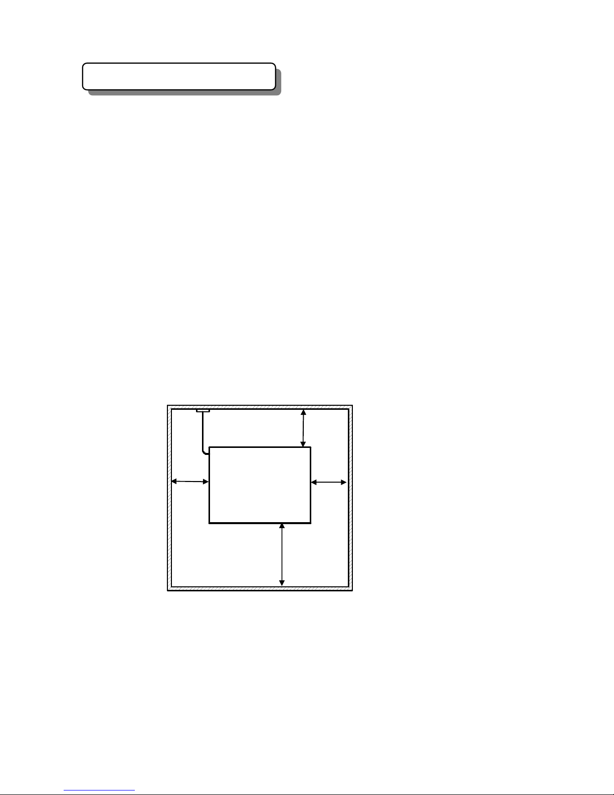
(6)
Keep the space around the system for taking out the power cord
in an emergency, for good ventilation and for maintenance, as the following.
(7)
The following points should be taken into consideration to select the
installation position.
- No dust, good ventilation
- No direct sun light
- Small vibration
3.3 Water supply/drain requirements
Water reservoir and waste liquid reservoir should be set below the system
bottom level.
32 cm
100 cm
50 cm
ANALYZER
FRONT
AC INPUT
50 cm
A
lso keep the space of at
least 100 cm over the
system.
(At the minimum)

Preface
T
0‑9
7. Storage and Transportation Requirements
(1) Indoor.
(2)
No direct sunlight.
(3)
No dust.
(4)
No upper load.
(5)
No dropping.
(6)
No throwing down.
(7)
Ambient temperature should be 1 ~ 45 Celsius degrees.
(8)
Ambient humidity should be 10 ~ 85% (no condensation).


1
Chapter 1
System configuration
1.1 Over view -------------------------------------------------------------------------------------1-2
1.2
Name of Each Unit ------------------------------------------------------------------------1-3
1.3 Panels ------------------------------------------------------------------------------------------1-6
1.4 Unit Layout ----------------------------------------------------------------------------------1-7
1.4.1 Unit Layout in the front view ------------------------------------------------1-7
1.4.2 Unit Layout in the right side view ----------------------------------------- 1-8
1.4.3 Unit Layout in the left side view ------------------------------------------- 1-9
1.4.4 Unit Layout in the rear view -------------------------------------------------1-10
1.4.5 Unit Layout of the first floor---------------------------------------------------1-11
1.4.6 Unit Layout of the second floor ----------------------------------------------1-12
1.4.7 Unit Location of the upper deck ---------------------------------------------1-13
Chapter 2
Functions and Movement of the System
2.1 Functions and Movement ----------------------------------------------------------------2-2
2.2 Analysis Process and Optical Measurement Point ------------------------------ 2-4
2.3 Automatic Analysis Process ------------------------------------------------------------2-5
2.4 Reagent Dispensation Process-----------------------------------------------------------2-8
2.5 Sample Dispensation Process ----------------------------------------------------------2-11
Chapter 3
Explanations about Units
3.1 Sampler (STF) --------------------------------------------------------------------------------3-2
3.2 Sample Pipette (STM) ------------------------------------------------------------------- 3-6
3.3 Sample Pump (SP) -----------------------------------------------------------------------3-11
3.4 Reagent Tray (RGT) --------------------------------------------------------------------- 3-14
3.5 Reagent Pipette (RTM) -------------------------------------------------------------------3-22
3.6 Reagent Pump (RP) ----------------------------------------------------------------------3-26
3.7 Reaction Tray (RCT) --------------------------------------------------------------------3-30
3.8 Mixing unit -1, -2 (MU-1, MU-2) ------------------------------------------------------ 3-35
3.9 Mixing Pump (MP) ------------------------------------------------------------------------ 3-38

2
3.10 Spectrophotometer (SPM) ------------------------------------------------------------3-40
3.11 Reaction Cuvette Washing Mechanics (CWS) ----------------------------------3-44
3.12 Reaction Cuvette Washing Pump (CWP) ----------------------------------------3-48
3.13 Washing Solution Pre-heater (WSH) ---------------------------------------------3-52
3.14 Probe Washing Pump (PWP) --------------------------------------------------------3-56
3.15 Waste Liquid Pump-1, 2 (DP-1) ----------------------------------------------------3-60
Chapter 4
Control PCB
4.1 MCPU PCB ---------------------------------------------------------------------------------4-2
4.2 SCPU PCB --------------------------------------------------------------------------------4-5
4.3 UCNT-1 PCB -----------------------------------------------------------------------------4-8
4.4 UCNT-2 PCB-------------------------------------------------------------------------------4-12
4.5 LAMP DC PCB ---------------------------------------------------------------------------4-16
4.6 PM DRV PCB -----------------------------------------------------------------------------4-19
4.7 TCD PCB -----------------------------------------------------------------------------------4-22
4.8 SSRAC PCB -------------------------------------------------------------------------------4-24
4.9 MOTHER BOARD ----------------------------------------------------------------------4-27
4.10 Shift of AC Input Voltage -------------------------------------------------------------4-29
Chapter 5
Hidden Screens of Maintenance
5.1 How to Open the Hidden Screens and Explanation of Various Screens
5.1.1 How to Open the Hidden Screens ------------------------------------------5-2
5.1.2 Explanation of Various Screens ------------------------------------------ 5-4
5.2 Password Setting
5.2.1 Password Setting Procedure -------------------------------------------------5-5
5.2.2 Password Setting of Patient Information-------------------------------- 5-7
5.3 Result Print Setting -----------------------------------------------------------------------5-8
5.4 Temperature Monitor Screen ----------------------------------------------------------5-9

3
5.5Machine offset screen
------------------------------------------------------------------ 5-11
5.6Outline of manual operation screens
-------------------------------------------- 5-12
5.6.1 STF (Sampler) --------------------------------------------------------------------5-13
5.6.2 STM-R (Sample probe - rotation)------------------------------------------5-14
5.6.3 STM-UD (Sample probe - up/down) --------------------------------------5-15
5.6.4 SP (Sample pump) -------------------------------------------------------------5-16
5.6.5 RGT (Reagent tray)------------------------------------------------------------ 5-17
5.6.6 RTM-R (Reagent probe - rotation) ----------------------------------------5-18
5.6.7 RTM-UD (Reagent probe- up/down)-------------------------------------- 5-19
5.6.8 RP (Reagent pump) ----------------------------------------------------------5-20
5.6.9 RCT (Reaction tray) -----------------------------------------------------------5-21
5.6.10 MU-1 (Mixing unit-1) --------------------------------------------------------5-22
5.6.11 MU-2 (Mixing unit-2) --------------------------------------------------------5-23
5.6.12 MP (Mixing pump)------------------------------------------------------------- 5-24
5.6.13 CWS (Reaction cuvette washing station) ------------------------------5-25
5.6.14 CWP (Reaction cuvette washing pump) -------------------------------5-26
5.6.15 PWP (Probe washing pump) ----------------------------------------------5-27
5.6.16 DP-1/2 (Drainage pump – 1, 2)--------------------------------------------- 5-28
5.6.17 DETECTOR (Colorimetry detector) -------------------------------------5-29
5.6.18 COVER (Sample & Top Covers Lock & Unlock) --------------------5-30
5.7 Manual Function Sub-screens --------------------------------------------------
5-31
5.7.1 Encoder Screen ----------------------------------------------------------------5-31
5.7.2 Sensor Screen -------------------------------------------------------------------5-32
5.7.3 Manual Auto Screen --------------------------------------------------------- 5-33
5.7.4 Gain Screen ---------------------------------------------------------------------5-35
5.7.5 PF BTN Screen ----------------------------------------------------------------5-37
Appendix 1
Mechanical Assembly Drawing
1 System Piping Diagram -------------------------------------------------------------- ASSY-1
2 ISE Piping Diagram ------------------------------------------------------------------- ASSY-2
3 Sampler (STF) --------------------------------------------------------------------------- ASSY-3
4 Sample Pipette (STM) ------------------------------------------------------------------ ASSY-4
5 Sample Pump (SP) --------------------------------------------------------------------- ASSY-5

4
6 Reagent Tray (RGT) ------------------------------------------------------------------- ASSY-6
7 Reagent Pipette (RTM) ----------------------------------------------------------------ASSY-7
8 Reagent Pump (RP) -------------------------------------------------------------------- ASSY-8
9 Reaction Tray (RCT) -------------------------------------------------------------------ASSY-9-1/2
ASSY-9-2/2
10 Mixing Unit-1, 2 (MU-1, MU-2) ----------------------------------------------------ASSY-10
11 Mixing Pump (MP) --------------------------------------------------------------------- ASSY-11
12 Spectrophotometer (SPM) ------------------------------------------------------------ASSY-12
13 Reaction Cuvette Washing Station (CWS) --------------------------------------ASSY-13
14 Reaction Cuvette Washing Pump (CWP) ----------------------------------------ASSY-14
15 Washing Solution Pre-heater (WSH) ---------------------------------------------ASSY-15
16 Probe Washing Pump (PWP) --------------------------------------------------------ASSY-16
17 Waste Liquid Pump -1,2 (DP-1, DP-2) ------------------------------------------- ASSY-17
18 Water Supply Reservoir --------------------------------------------------------------ASSY-18
19 Washing Solution Reservoir --------------------------------------------------------- ASSY-19
20 Waste Liquid Reservoir ---------------------------------------------------------------ASSY-20
21 Reaction Waste Reservoir ------------------------------------------------------------ ASSY-21
Appendix 2
Electrical Wiring Drawing
1 Electrical Block Diagram -1/2 --------------------------------------------------------WIRING-1
Electrical Block Diagram -2/2 ------------------------------------------------------- WIRING -2
2 AC/DC Power Supply 1/3 ------------------------------------------------------------- WIRING -3
AC/DC Power Supply 2/3 ------------------------------------------------------------- WIRING -4
AC/DC Power Supply 3/3 ------------------------------------------------------------- WIRING -5
3 Sampler (STF) ---------------------------------------------------------------------------WIRING -6
4 STM Unit ----------------------------------------------------------------------------------WIRING -7
5 Sample Pump (SP) ---------------------------------------------------------------------WIRING -8
6 Reagent Tray (RGT) ------------------------------------------------------------------- WIRING -9
7 Reagent Pipette (RTM) ----------------------------------------------------------------WIRING -10
8 Reagent Pump (RP) -------------------------------------------------------------------- WIRING -11
9 Reaction Tray (RCT) -------------------------------------------------------------------WIRING -12
10 Mixing Mecha.-1 (MU-1) -------------------------------------------------------------- WIRING -13
11 Mixing Mecha.-2 (MU-2) -------------------------------------------------------------- WIRING -13
12 Mixing Pump (MP) --------------------------------------------------------------------- WIRING -13
13 Spectrophotometer (SPM) ------------------------------------------------------------WIRING -14
14 Cuvette Wash Station (CWS) ------------------------------------------------------- WIRING -15

5
15 Cuvette Washing Pump (CWP) ---------------------------------------------------- WIRING -15
16 Washing Solution Pre-heater (WSH) --------------------------------------------- WIRING -16
17 Probe Washing Pump (PWP) -------------------------------------------------------- WIRING -16
18 Drain Pump-1 (DP-1) ------------------------------------------------------------------ WIRING -17
19 Drain Pump-2 (DP-2) ------------------------------------------------------------------ WIRING -17
20 Water Supply Reservoir -------------------------------------------------------------- WIRING -17
21 Washing Solution Reservoir (Alkaline) ------------------------------------------- WIRING -17
22 Washing Solution Reservoir (Acidic)----------------------------------------------- WIRING -18
23 Waste Liquid Reservoir --------------------------------------------------------------- WIRING -18
24 Reaction Waste Reservoir ------------------------------------------------------------ WIRING -18
25 Solenoid Valve --------------------------------------------------------------------------- WIRING -18
26 Printer ------------------------------------------------------------------------------------ WIRING -19
27 Barcode Reader -------------------------------------------------------------------------- WIRING -19
28 MCPU PCB ------------------------------------------------------------------------------- WIRING -20
29 SCPU PCB -------------------------------------------------------------------------------- WIRING -21
30 UCNT-1 PCB ----------------------------------------------------------------------------- WIRING -22
31 UCNT-2 PCB ----------------------------------------------------------------------------- WIRING -23
32 LAMPDC PCB --------------------------------------------------------------------------- WIRING -24
33 PMDRV PCB ----------------------------------------------------------------------------- WIRING -25
34 SP PCB ------------------------------------------------------------------------------------ WIRING -26
35 SSRAC PCB ------------------------------------------------------------------------------ WIRING -27
36 TCD PCB ----------------------------------------------------------------------------------WIRING –27
Periodic Check List


Service Manual
Chapter 1
1‑1
Chapter 1 System Configuration
This chapter explains parts, layout and so on.
Contents
1. 1. Over View ------------------------------------------------------------- 1-2
1. 2. Name of Each Unit ------------------------------------------------- 1-3
1. 3. Panels ----------------------------------------------------------------- 1-6
1.4. Unit Layout ---------------------------------------------------------- 1-7
1.4.1. Unit layout in the front view ------------------------------- 1-7
1.4.2. Unit layout in the right side view--------------------------- 1-8
1.4.3. Unit layout in the left side view ----------------------------- 1-10
1.4.4. Unit layout in the rear view----------------------------------- 1-11
1.4.5. Unit layout of the first floor ----------------------------------- 1-12
1.4.6. Unit layout of the second floor-------------------------------- 1-13
1.4.7. Unit layout on the upper deck --------------------------------1-14
1‑2
1.
SYSTEM CONFIGURATION
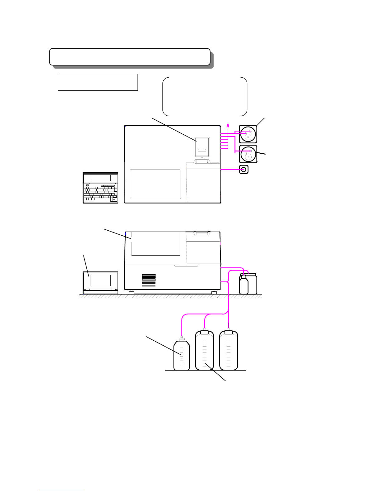
1.1.Over View
Fig. 1-1 Over view of the analyzer
Water reservoir
Reaction waste reservoir
Reaction sol. separating
collection reservoir
(option)
<
System front view>
<
Top view>
ISE (Waste liquid reservoir)
A
cidic washing solution
reservoir
A
nalyzer
Top cover
Printer
Personal computer
Reaction waste liquid
reservoir (o
p
tion)
Water reservoir
Waste liquid reservoir
A
lkaline washing
solution reservoir
Service Manual
Chapter 1
1‑3
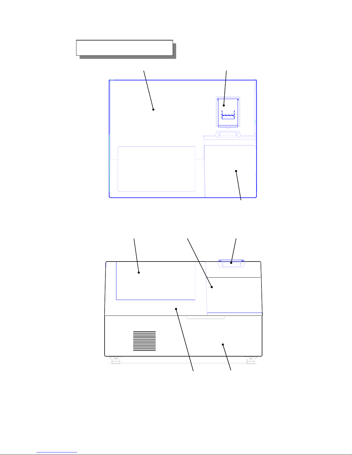
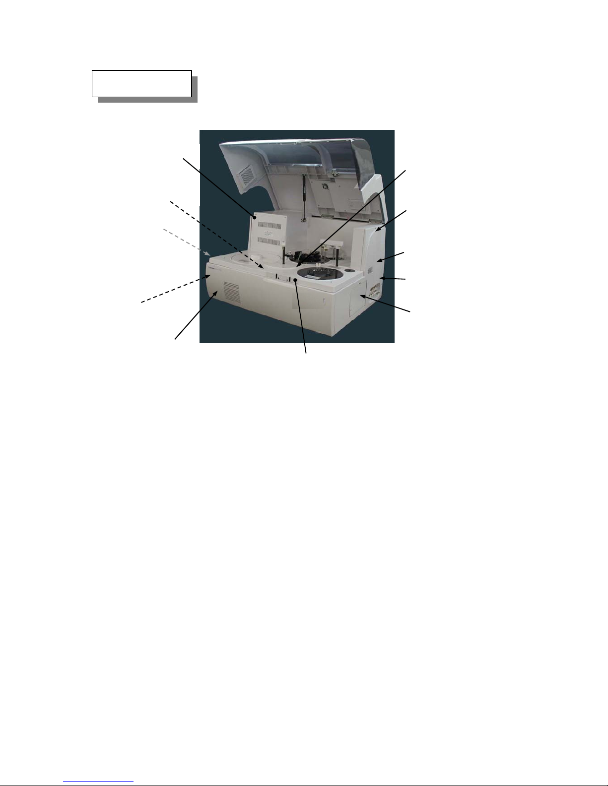
1.2.Name of Each Unit
Fig. 1-2 Bird’s-eye view
Top Cover
Printer
Sampler Cover
Printer S
W
Sampler CoverInner Cover
Front PanelTop Cover
Fig. 1-3 System Front view
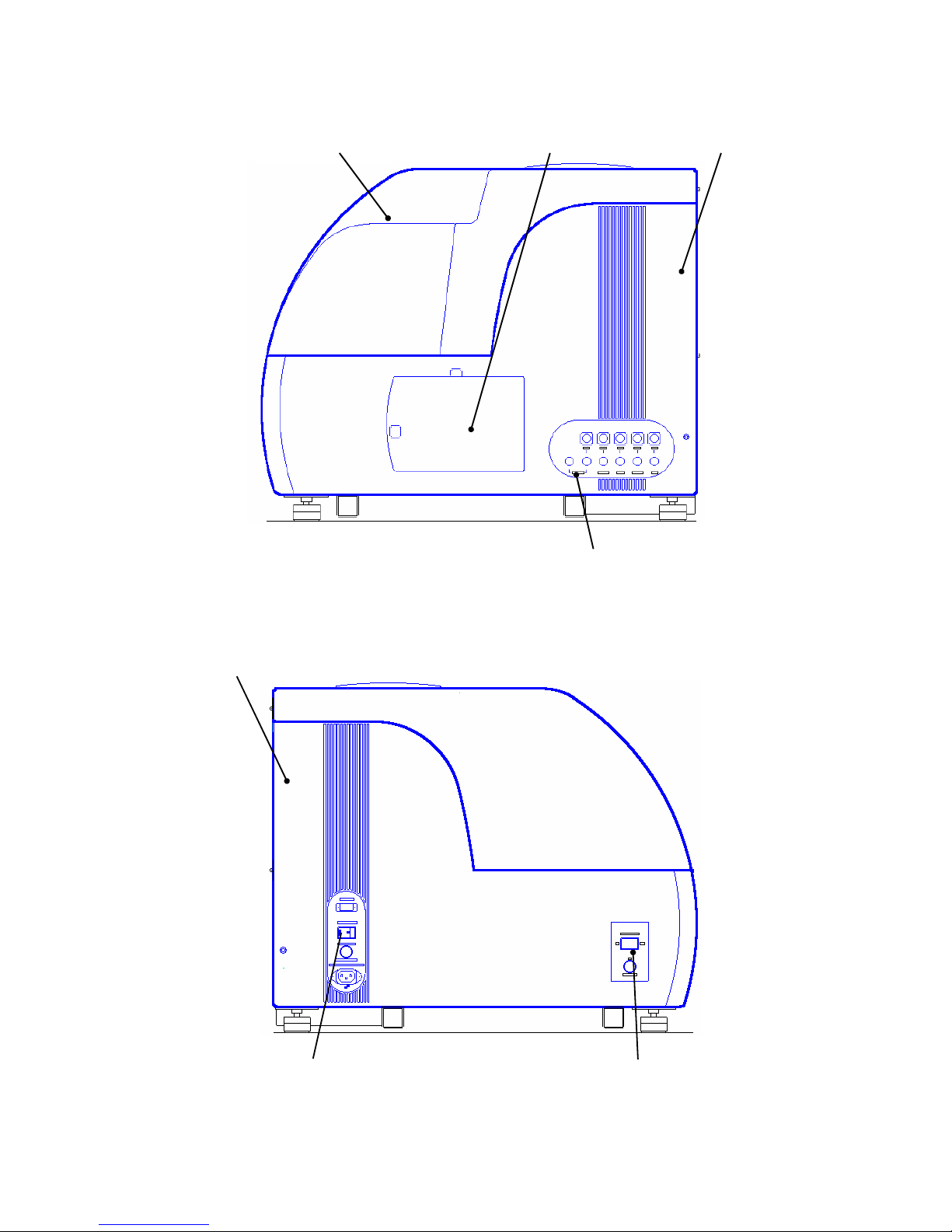
1‑4
Fig. 1-4 Right side elevation of the analyzer
Fig. 1-5 Left side elevation of the analyzer
Water Supply/Drain Panel
Top Cover
Main Power Switch
Left Side Panel
System Power Switch
ISE Door
Right Side Panel

Service Manual
Chapter 1
1‑5
Fig. 1-6 Rear side view
Fig. 1-7 The view when top cover is open
V
entilation Fan
Rear Panel (upper)
Rear Panel (lower)
Printer I/F PCB
Reagent Tray
Gas Damper
Sampler
Reagent Probe
Control PCB
Reaction Tray
Reaction Cuvette
Washing Station
Sample Probe
Top Cover
1‑6
1.3.Panels
Fig. 1-8 System slant view
There are nine panels. ( Please refer to Fig. 1-6.)
1. Front panel
It is fixed by one screw and four catches. When removing, loosen the screw and
pull the panel towards you.
2. Top panel
This panel is fixed by five screws. When removing, remove front panel first, and
push over upper chassis after removing upper screws of right and left side
panels.
3. Right side panel
This panel is fixed by the upper and lower two screws and three catches.
When removing, open top cover first and remove two screws to leave ISE door
ajar. And loosen right screw of the reverse side of front panel.
4. Left side panel
This panel is fixed by the upper and lower screws (two) and four catches.
When removing, open top cover first to remove two screws. And loosen the right
side screw of the reverse side of front panel.
5. Rear panel (upper)
The upper panel in the back view. Fixed by nine screws. This panel has a fan.
6. Rear panel (lower)
The lower panel in the back view. Fixed by ten screws.
Right Side Panel
Front Panel
Top Panel
ISE Door
Left Side Panel
Right Side
Fixing Screw
Right Side Panel
Fixing Screw
Front Panel
Fixing Screw
Top Panel
Fixing Screw
Top Panel
Fixing Screw
Upper Chassis
Fig. 1-8 System slant view
Service Manual
Chapter 1
1‑7
1.4.Unit Layout
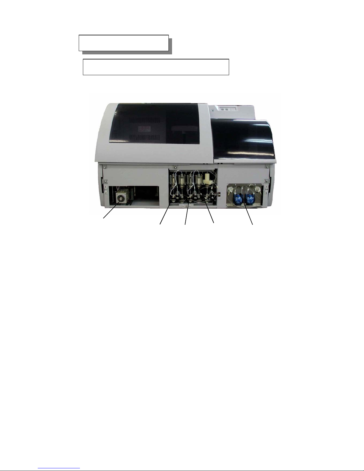
1.4.1. Unit Layout in the Front View
The drawing below shows front view when the front panel is removed.
Fig. 1-9 Front view
1. Reagent pump (RP) Consists of a pump to aspirate/dispense reagent and a
pump to wash the inside of reagent probe.
2. Sample pump (SP) Consists of a pump to aspirate/dispense sample and a
pump to wash the inside of sample probe.
3. Probe washing pump Washing water supply pump for the outside of reagent
and sample probes.
4. ISE pump Consists of a pump to pour calibrant into sample pot
and a pump to pour sample or calibrant on to electrode
and to drain.
5. Thermo module Module to control the temperature for regent tray.
1 2 3 4
5
1‑8
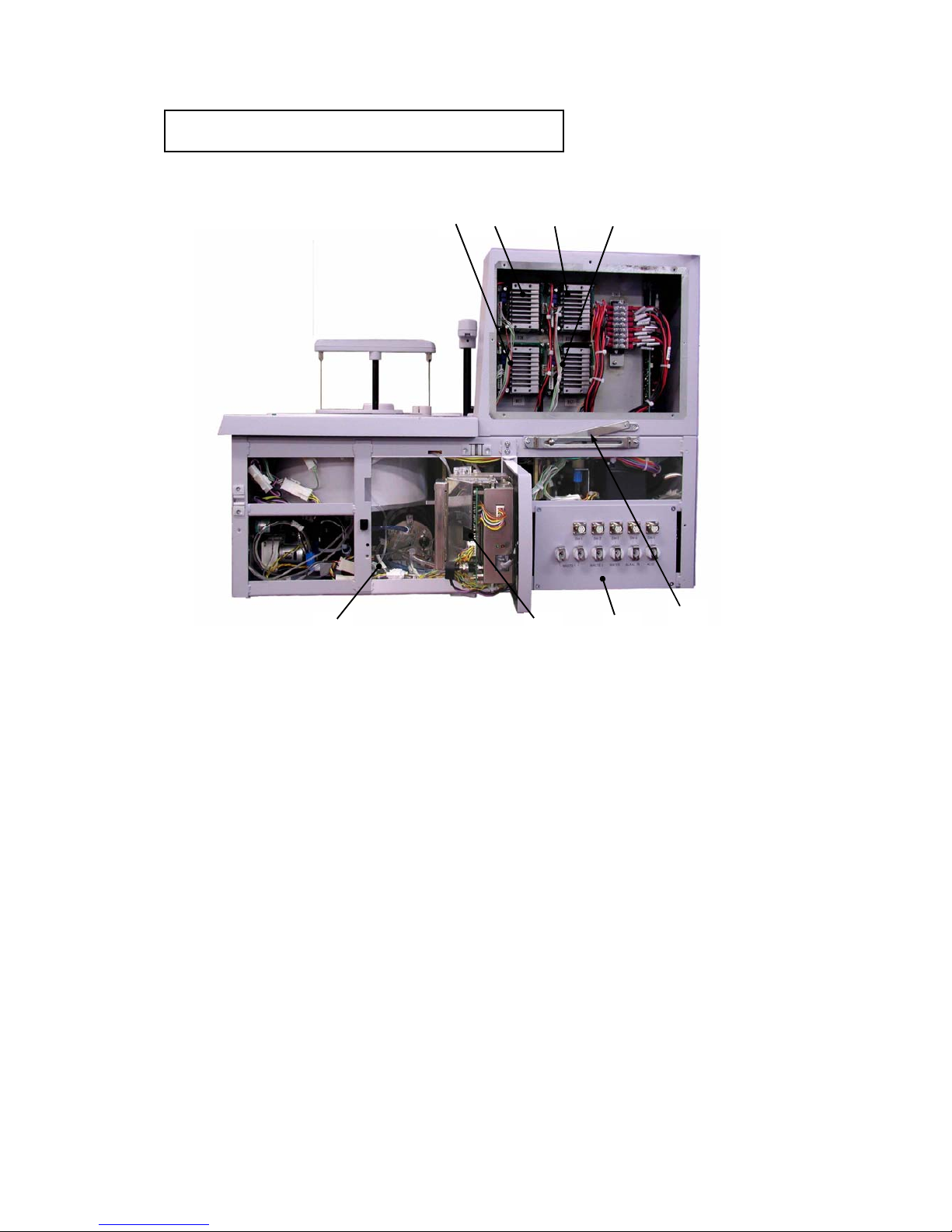
1.4.2. Unit Layout in the Right Side View
This drawing shows the right side view when the right side panel is removed.
Fig. 1-10 Unit layout in the right side view
1. Five-phase-motor driver Stepping motor driver for STM turn
2. Five -phase-motor driver Stepping motor driver for RTM turn
3. Five-phase-motor driver Stepping motor driver for RCT turn
4. Five -phase-motor driver Stepping motor driver for RGT turn
5. Preheat (WSH) Unit to preheat washing solution or detergent
6. ISE unit Unit to measure electrolyte
7. Water supply and drainage panel Panel for washing solution supply and drainage
8. Slide stay (right) The supporting part when chassis is slanted.
1
3
2 4
6
7
5
8
Service Manual
Chapter 1
1‑9
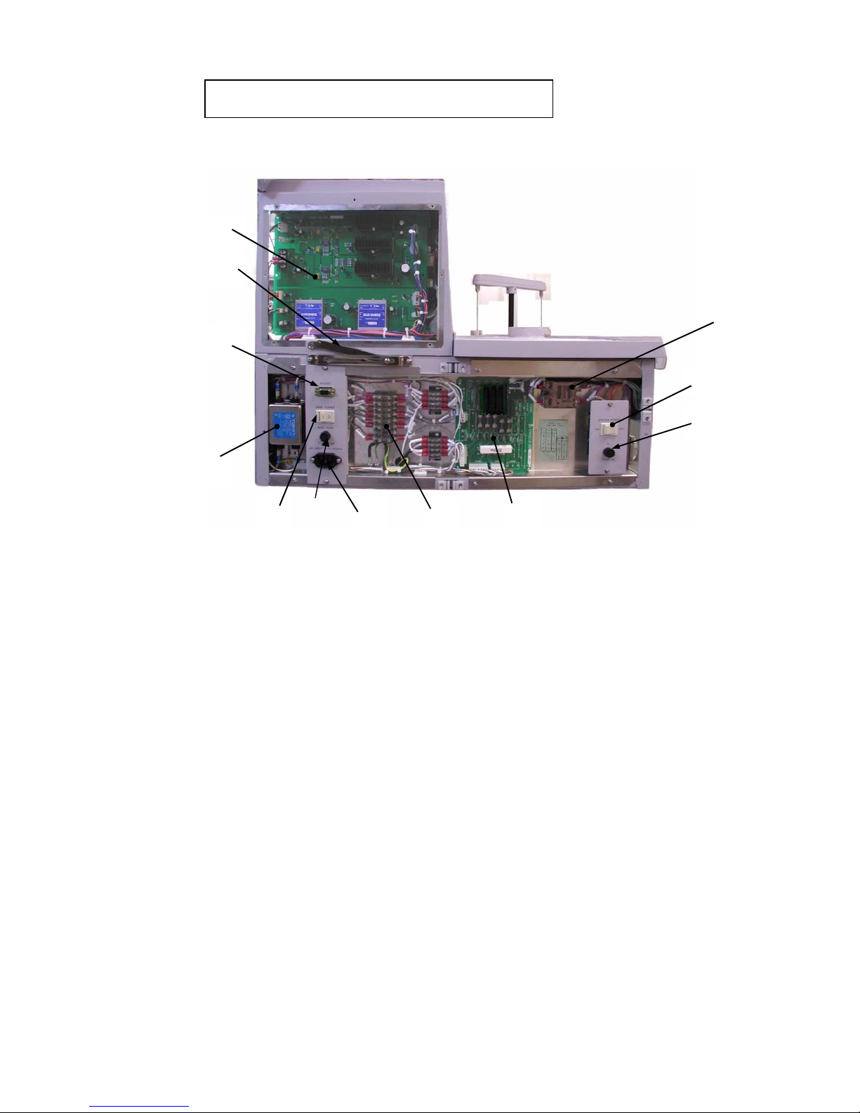
1.4.3. Unit Layout in the Left Side View
This drawing shows the left side view when the left side panel is removed.
Fig. 1-11 Unit layout in the left side view
1. Lamp DC PCB PCB to supply power to light source lamp or others
2. Noise filter Filter to eliminate noise from power supply
3. RS-232C connector
Connector to personal computer (RS-232C)
4. Main power switch When the switch on, cooling function is on.
5. AC power input Plug for AC power
6. Fuse Fuses from F2 to F9 are set.
F9 (T-250V 5A)
F8 (T-250V 2A)
F7 (T-250V 3.15A)
F6 (T-250V 1A)
F5 (T-250V 1A)
F4 (T-250V 3.15A)
F3 Not connected
F2 (T-250V 2A)
The rating plate for fuse is attached to the inside of
left side panel.
7. SSR AC PCB PCB to control the unit operated at AC 100V.
8. SSR On-Off switch to control the temperature for reagent
cooling system.
9
7654
2
1
3
10
8
11
12

1‑10
9. System power switch When this switch on, the system is started automatically.
10. Fuse System fuse F1 (T-250V 5A)
11. Slide stay (left)
The supporting part when chassis is slanted.
12. Fuse Main Fuse (T-250V 6.3A)
Service Manual
Chapter 1
1‑11
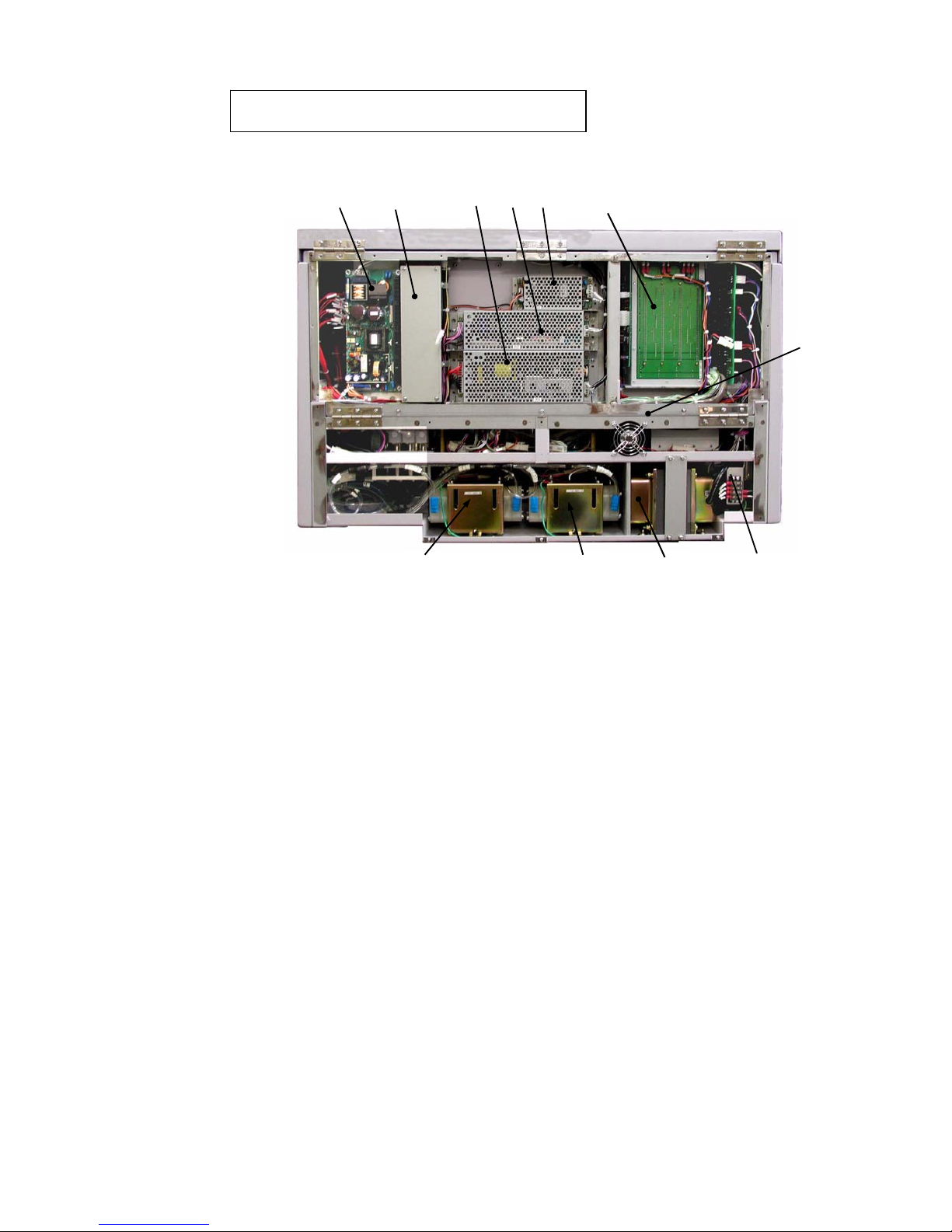
1.4.4. Unit Layout in the Rear View
This drawing shows the rear view when the rear panel is removed.
Fig. 1-12 Unit layout in the rear view
1. DC plus-minus 15V/ +5V power supply SWT100-5FF type
2. DC plus-minus 12V power supply LDA 100W-12 type
3. Ventilation fan Fan to be operated at DC 12V
4. DC plus-minus 24V power supply LDA150W-24-SNY type
5. DC plus-minus 15V power supply LDA75F-15-SNY type
6. DC plus-minus 5V power supply LDA15F-5-SNY type
7. Mother board Mother board PCB
8. DP-1 Pump to aspirate reaction cuvette washing
solution and to degas from degasser.
9. DP-2 Pump for reaction waste liquid and washing
trough waste water.
10. Power transformer Input voltage (AC100V, 115V or 230V.)
Output voltage (AC100V)
11. Input voltage switch Switch for input voltage, 100V, 115V or 230V
2 1
3
4 5 76
1098 11
1‑12
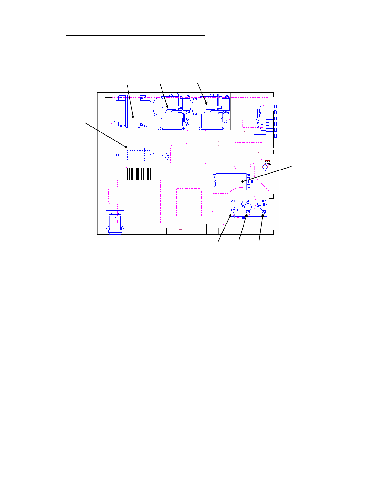
1.4.5. Unit Layout of the First Floor
This drawing shows unit location fixed to lower chassis.
Fig. 1-13 Unit layout of the first floor
1. Power transformer
Input voltage (AC100V, 115V or 230V.)
Output voltage (AC100V)
2. DP-2
Pump for reaction waste liquid and washing
trough waste water.
3. DP-1
Pump to aspirate reaction cuvette washing
solution and to degas from degasser.
4. Degasser
Module to remove air in washing water.
5. Washing solution pre-heater Heater for reaction cuvette and probe
washing solution and for alkaline and acidic
washing solution.
6. Electromagnetic valve EV-3 Valve for switching piping lines of R1 and
R2 probes.
7. Electromagnetic valve EV-5 Valve for switching aspiration lines of dry
tips and degasser.
8. Electromagnetic valve EV-6 Valve for switching aspiration lines of WSH
and washing trough.
1 2 3
4
5
6 7 8
 Loading...