

Toky AI208 Series, AI208-*-DC18, AI208-*-IRC18, AI208-*-ISC18, AI208-*-RB18 User Manual
...
1/10page KKAI208C01A-A1-20140904
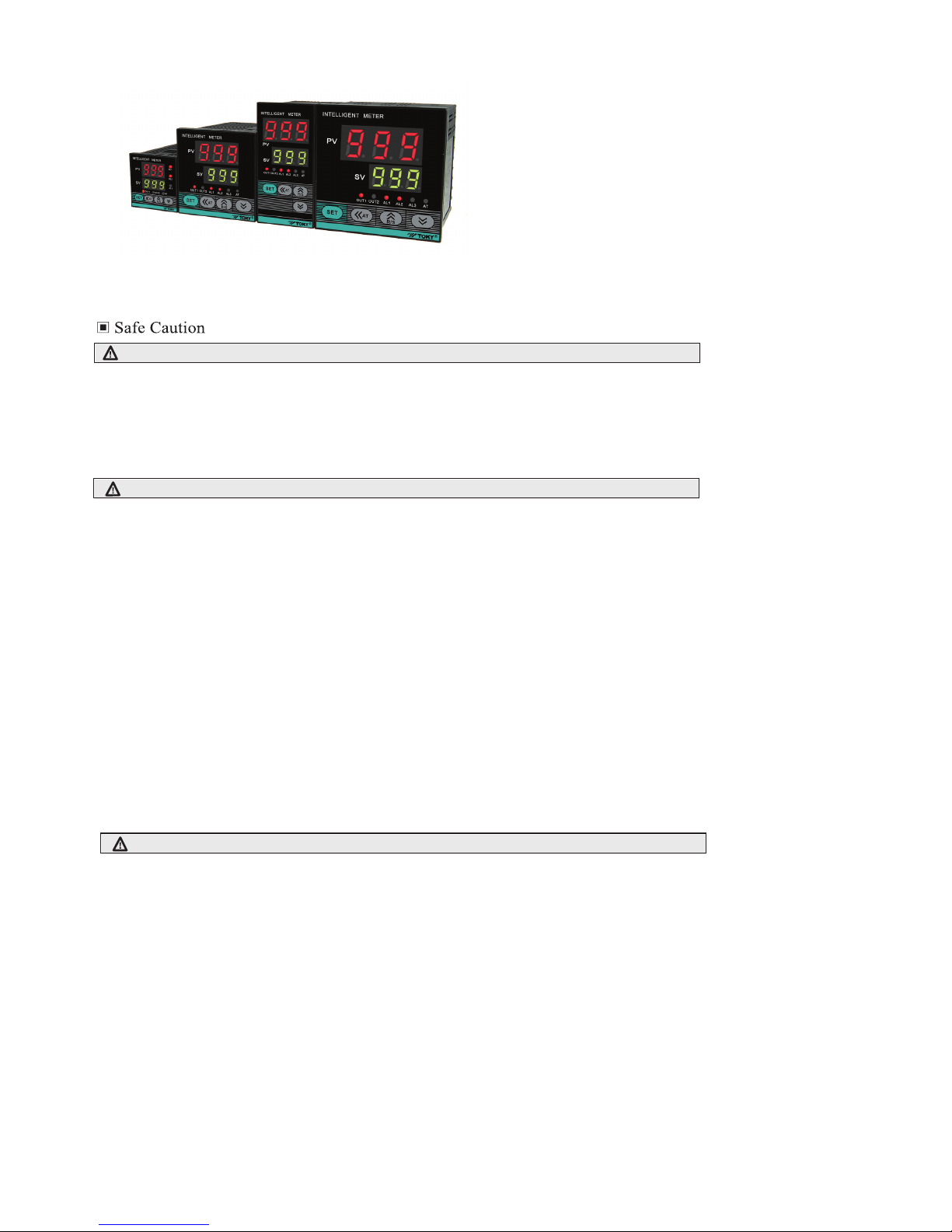
AI208 Series Temperature Controller User Manual
⊙Optional input signal types and models
⊙With many functions of measured display,control output,alarm
output,analog output,RS485 communication,etc.
⊙Optional many types of PID arithmetic and with auto-tuning function.
⊙Using for industrial machinery, machine tools,measuring instruments.
⊙Economical and easy operation.
Features:
The instruction explain instrument settings, connections,name and etc,please read carefully before you use the temperature controller.
Warning
1)When the failure or abnormal of products lead to a system of major accidents,please set the proper protection circuit in the external.
2)Please don`t plug in before completing all the wire.Otherwise it may lead to electric shock, fire, fault.
3)Not allow to use outside the scope of product specification,otherwise it may lead to fire,fault.
4)Not allow to use in the place where is inflammable and explosive gas.
5)Do not toch wire connectors when the power on,otherwise you may get an electric-shock.
6)Do not remove,repair and modification this product,otherwise it may lead to electric shock, fire, fault.
Caution
1)The product should not be used in a nuclear plant and human life associated medical equipment.
2)The product may occur radio interference when it used in home.You should take adequate countermeasures.
3)The product get an electric shock protection through reinforced Insulation. when the product is embedded in the devices and wiring,please subject to the
specification of embedded devices.
4)In order to prevent surge occurs,when using this product in the place of over 30m indoor wiring and wiring in outdoor,you need to set the proper
surge suppression circuitry.
5)The product is produced based on mounting on the disk.In order to avoid to touch the wire connectors,please take the necessary measures on the product
6)Be sure to observe the precautions in this manual, otherwise there is a risk of a major injury or accident.
8)To prevent to damage the machine and prevent to machine failure, the product is connected with power lines or large capacity input and output lines
and other methods please install proper capacity fuse or other methods of protection circuit.
9)Please don't put metal and wire clastic mixed with this product,otherwise it may lead to electric shock, fire, fault.
10)Please tighten screw torque according to the rules.If not,it may lead to electric shock and fire.
11)In order not to interfere with this products to dissipate heat, please don't plug casing around the cooling vent hole and equipment.
12)Please don`t knock or rub the panel with rigid thing.
13)The readers of this manual should have basic knowledge of electrical,control, computer and communications.
14)The illustration, example of data and screen in this manual is convenient to understand,instead of guaranteeing the result of the operation.
15)In order to use this product with safety for long-term,regular maintenance is necessary. The life of some parts of the equipments are by some restrictions,
but the performance of some will change for using many years.
16)Without prior notice, the contents of this manual will be change. We hope these is no any loopholes, if you have questions or objections, please contact us.
1.Installation:
1)This product is used in the following environmental standards.
(IEC61010-1)[Overvoltage categoryⅡ、class of pollution 2]
2)This product is used in the following scope:surrounding environment, temperature, humidity and environmental conditions.
Temperature:0~50℃;Humidity:45~85%RH;Environment condition:Indoor warranty,The altitude is less than 2000m.
3)Please avoid using in the following places:
The place will be dew for changing temperature;with corrosive gases and flammable gas;with vibration and impact;with water, oil, chemicals, smoke and steam
facilities with Dust, salt, metal powder;and with clutter interference, static electric and magnetic fields, noise;where has air conditioning or heating of air blowing
directly to the site.
4)On the occasion of the installation, please consider the following before installing several.
In order to protect heat saturated, please ensure adequate ventilation space.
Please consider connections and environment,and ensure that the products below for more than 50mm space.
Please avoid to installed over the machine of the calorific value(Such as heaters, transformer, semiconductor operations, the bulk resistance).
When the surrounding is more than 50℃, please using the force fan or cooling fans.But don't let cold air blowing directly to the product.
In order to improve the anti - interference performance and security, please try to stay away from high pressure machines, power machines to install.
Don`t install on the same plate with high pressure machine and the product.
The distance should be more than 200mm between the product and power line.
Caution of Install & Connection:
AI208 6
R
□
C
18 D
D:Version
10:Single loop input without communication 18:Single loop input with RS485
B:1loop alarm output C: 2loop alarm A: No alarm
6:48W*96H*100L 7:72W*72H*100L 4: 48W*48H*100L
9:96W*96H*100L 8:96W*48H*100L
AI208series temperature controller
2/10 page KKAI208C01A-A1-20140904
2
2
2
1
1
AI208-□-IRC18
AI208-
□-ISC18
AI208-
□-DC18
AI208-
□-RB10
AI208-
□-SB10
R:Relay output S:SSR output D:DC 4-20mA(set to analog output through ACT menu) K:SCR output(to be order)
I :4~20mA analog output (can adjust the current output through ACT menu) Blank:No
注
2.Cable caution:
1)Please use specified compensation wire in the place of TC input;Please use insulated TC if the measured device is heated metal.
2)Please use the cable of lesser resistance in the place of RTD input,and the cable(3 wire) must be no resistance difference,but the total length is within 5m.
3)In order to avoid the effect of noise,please put the input dignal away from meter cable,power cable,load cable to wiring.
4)In order to reduce the power cables and the load power cables on the effect of this product,please use noise filter in the place where easy to effect.
You must install it on the grounding of the disk if you use the noise filter,and make the wiring to be shortest between noise filter output side and power connectors.
Don`t install fuse and switch on the wiring of noice filter output side,otherwise it will reduce the effect of noise filter.
5)It takes 5s from input power to output.If there is a place with interlocking actions circuit signal,please use timer relay.
6)Please use twisted pair with a shield for analog output line,and to ensure the reliabilty of signal,and connect Common mode choke on the front of sinal receiver to suppress
lines affected by interference if necessary,so that to
7)Please use twisted pair with a shield for remote RS485 communication cable,and deal with the shield on the host side earth,otherwise it will reduce the effect of noise filter.
8)This product is not the fuse;please set according to rated voltage 250V,rated current 1A if you need;fuse type:relay fuse.
9)Please use the suitable screw force and crimp terminal.
The screw terminal size:M3X8(with 6.8X6.8 square base)
Recommended tightening torque:0.4N.m
Proper cables:0.25~1.65mm single cable/multiple core cable
10)Pla don`t put the Crimp terminal or bare wire part contact with adjacent connector.
Model Illustration
:TE series is only one 4~20mA output function.For the size of 6、8、9,when relay output/SSR output is together with DC 4~20mA,it has discrimination with “I”;
for example:IR,IS,etc,but it has not this type model for the size of 4、7.
Please note the input signal type when you choose the model. 1st type:TC/RTD/mV/Rt;2nd type:mA/V
Ordering Information
Model Control output Alarm
Analog 4~20mA
RS485
Relay / 4~20mA
SSR / 4~20mA
4~20mA
Relay
Yes
Yes
No
No
Yes
Yes
Yes
No
No
SSR
multiplex with main control
□:Optional dimensions
Specifications
1、Electrical parameters
Communication port
Current output
SSR output
Environment
Sample rate
2SPS
Power supply
Power consumption
Relay capacity
Storage enenvironment
Insulation impedance
ESD
Pulse traip
anti-interference
Lightning surge
Frequency drop
Dielectric strength
Total weight
AC 250V /3A Life of rated load>10w times
AC/DC 100~240V (85-265V)
< 6VA
Temperature of indoor:0~50℃ no condensation,Humidity:<85%RH,altitude<2000m
-10~60℃,no condensation
DC 24V pulse level,load<30mA
DC 4~20mA load < 500Ω,Temperature drift 250PPM
RS485 port Modbus-RTU procotol,max input 30units
Input,output,power cabinet>20MΩ
IEC/EN61000-4-2 Contact ±4KV /Air ±8KV perf.Criteria B
IEC/EN61000-4-4 ±2KV perf.Criteria B
IEC/EN61000-4-5 ±2KV perf.Criteria B
IEC/EN61000-4-29 0%~70% perf.Criteria B
Signal input & output & power 1500VAC 1min,below 60V Low voltage circuit between DC500V,1min
About 400g
K
J
E
PT100
CU50
CU100
0~50mV
4~20mA
0~10V
0~400Ω
-50~999
-50~400
-200~600
-50~150
-50~150
-199~999
-199~999
-199~999
-199~999
0~999
0~850
T
1℃
1℃
1℃
1℃
1℃
1℃
1℃
12bit
12bit
12bit
12bit
0.5%F.S±3digits
0.5%F.S±3digits
0.5%F.S±3digits
0.5%F.S±3digits
0.5%F.S±3digits
0.5%F.S±3digits
0.5%F.S±3digits
0.5%F.S±3digits
0.5%F.S±2℃
0.5%F.S±3℃
0.5%F.S±1℃
>500kΩ
>500kΩ
>500kΩ
>500kΩ
0.2mA
0.2mA
0.2mA
>500kΩ
100Ω
>1MΩ
0.2mA
0
1
2
3
4
5
6
7
8
9
10
(Ⅰ)
control output
Power Supply
S E T
R/S
3/10 page KKAI208C01A-A1-20140904
*
*
4
1
2
3
6
5
7
OUT1
SV
PV
OUT2 AL1 AL2 AL3 AT
AT
INTELLIGENTIZED METER
Shell material
Panel material
Power-off data protection
Protection level of panel
Safety Standard
The shell and panel frame PC/ABS (Flame Class UL94V-0)
PET(F150/F200)
10 years,times of writing:100w times
IP65(IEC60529)
IEC61010-1 Overvoltage category Ⅱ,pollution level 2,levelⅡ(Enhanced insulation)
2、measured signal specifications
Input type Measuring rangesymbol Resolution Accuracy
Input impedance/
auxiliary current
Code
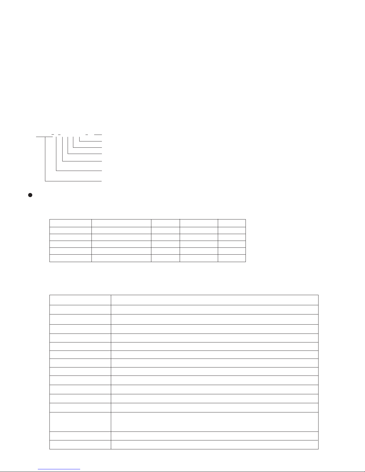
3、Isolation diagram
Please note when you choose the model
MCU(Ⅱ)
measure input
Relay
alarm output
Analog output
communication port
( I ) auxiliar power
“ ”:Isolation
Note: when there is no analog output,communication port between (Ⅰ)and(Ⅱ),part of specification(such as relay output) is isolation;
SSR output is no isolation.
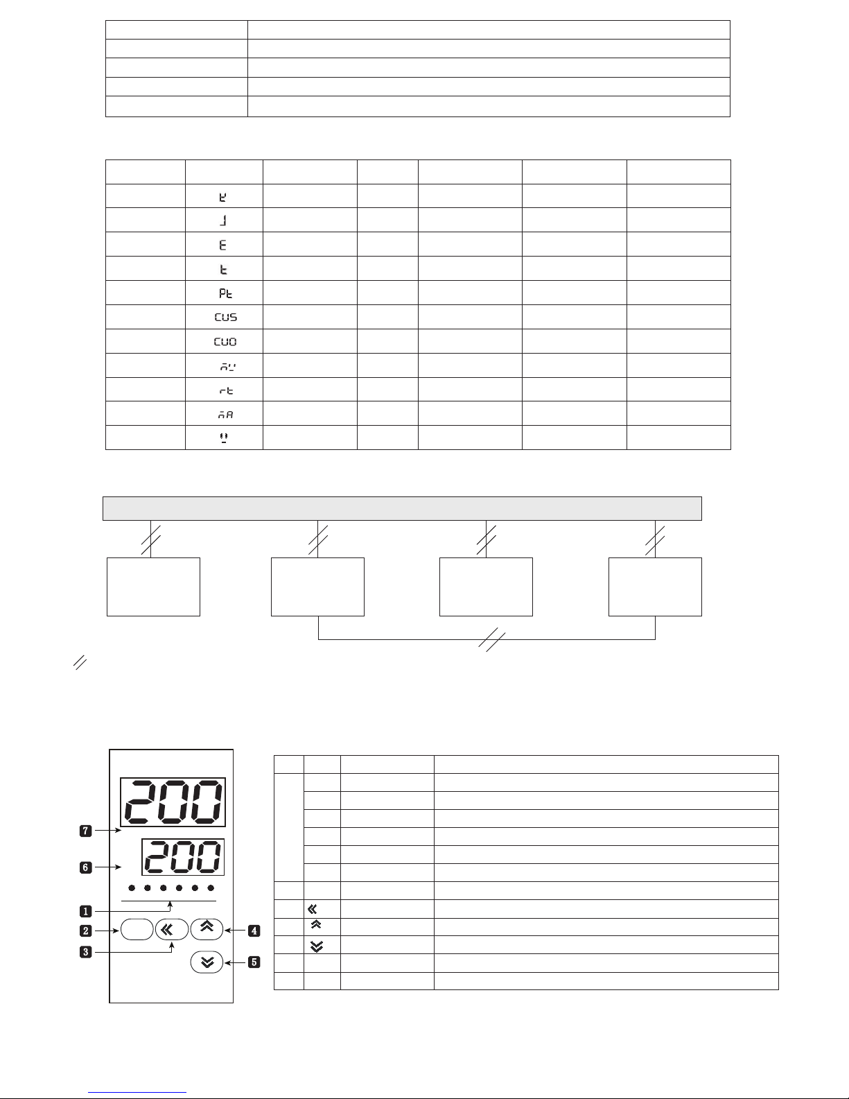
Name of universal panel
R/S
Menu key/ensure key,to use enter or back to modified mode or ensure/save parameters
Add key/R/S
Display window (green) Setting value/parameters display window,display “STP” =stop control
Display window (red) measured value/parameters code display window
Reduce key
Add key,long press it can reach switch of RUN/STOP mode under the measure control mode.
Reduce key
Activation key/shift key/AT setting key,long press to enter or back to auto-tuning
under the measure control mode.
No.
symbol
Name Function
1
2
AL1
AL2
AL3
Alarm1#
indicator light(red)
Alarm2#
indicator light(red)
Alarm3#
indicator light
3
AT indicator light(green)
Shift/AT key
SET function key
OUT1
OUT2
AT
SET
SV
PV
5
4
7
6
OUT2 indicator light(red)
OUT1 indicator light(red)
AT
Host control output indicator light,it light when the output is 0N
Cooling output indicator light,it light when the output is 0N
1st loop alarm output indicator light,alarm output with light,no alarm output without light.
2nd loop alarm output indicator light,alarm output with light,no alarm output without light.
AL3:This product has no the function
Auto-tuning indicator light,it show setting state when it light
 Loading...