

TOKOM KV1851ETR Datasheet

KV1851E
VARIABLE CAPACITANCE DIODE
FEATURES
■ Very Small URD Surface Mount Package
■ Very Low Series Resistance
■ Large Capacitance Ratio (A = 3.9 minimum)
■ Excellent Linearity (CV Curve)
■ Very Small Capacitance Deviation at Tape/Reel
DESCRIPTION
The KV1851E is a variable capacitance diode designed for
UHF applications.
The KV1851E is available in a very small URD Surface
Mount Package.
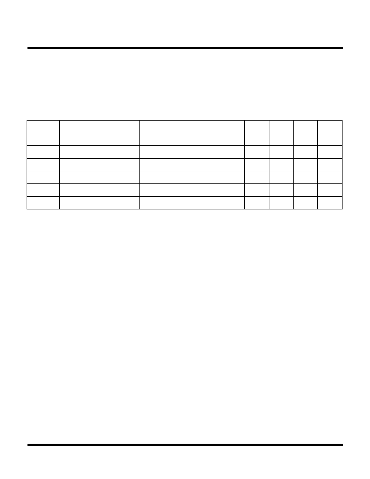
CLASSIFICATION
RANK
C
MIN 25.00 26.50 28.10
C
1
MAX 26.90 28.50 30.00
12 3
(Unit: pF)
APPLICATIONS
■ UHF Communications Equipment
■ Voltage Controlled Oscillator
■ 900 MHz Communications Systems
KV1851E
Note: Rank is determined after testing and marked on the
reel. All the diodes on a reel have the same rank, but rank
can not be specified when ordering.
ORDERING INFORMATION
KV1851E
Tape/Reel Code
TAPE/REEL CODE
TR: Tape Right
August 1999 TOKO, Inc. Page 1
KV1851E
ABSOLUTE MAXIMUM RATINGS
Reverse Voltage....................................................... 18 V
Forward Current .................................................... 10 mA
Power Dissipation ................................................ 50 mW
ELECTRICAL CHARACTERISTICS
Test conditions: T
SYMBOL PARAMETER TEST CONDITIONS MIN TYP MAX UNITS
= 25 °C
A
Storage Temperature Range ................... -55 to +150 °C
Operating Temperature Range ...................-55 to +85 °C
V
REV
I
REV
C
1
C
4
R
S
A Capacitance Ratio C
Note 1: Diode Capacitance measured with HP 4279A or equivalent instruments (at OSC level 20 mVrms, ± 5 mVrms).
Note 2: Series Resistance measured with HP 4191A or equivalent instruments.
Reverse Voltage I
Reverse Current V
Diode Capacitance 1 V
Diode Capacitance 4 V
Series Resistance V
= 10 µA 16 V
REV
= 10 V 5.00 nA
REV
= 1 V, f = 1 MHz 25.00 30.00 pF
REV
= 4 V, f = 1 MHz 4.90 7.00 pF
REV
= 4 V, f = 100 MHz 1.7
REV
/ C
1
4
3.90
Ω
Page 2 August 1999 TOKO, Inc.
 Loading...