

Page 1
TOKISTAR LIGHTING
INSTRUCTION MANUAL
Micro Tracklight Series 24 VDC
General Description
Tokistar’s Micro Tracklight Series operates at 24 VDC from
Class 2 Power Supplies. LED Modules with pivoting heads can
be positioned at any location on the track. Each LED module
consumes 1.6 watts. Each xture is labeled with load and operating voltage.
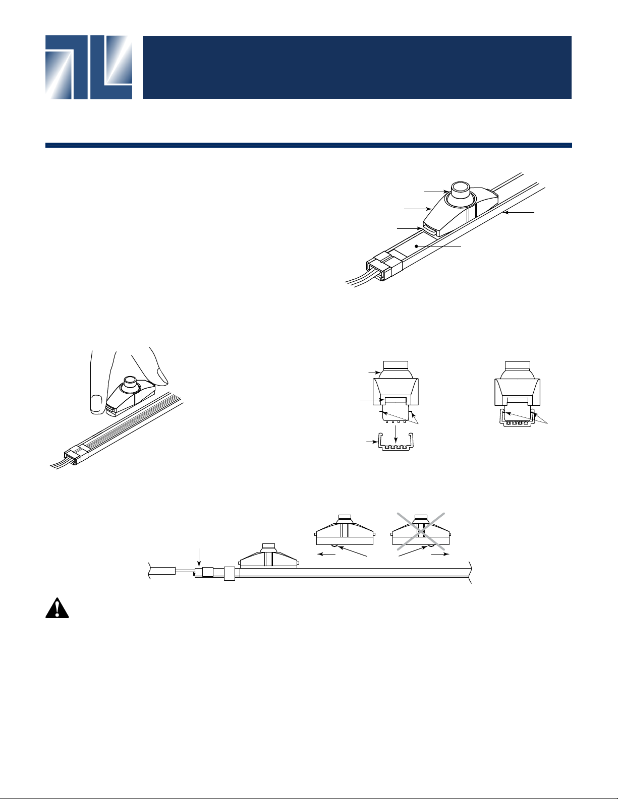
Step 1: Measure and cut the track to size.
Step 2: Determine position of LED Modules on track.
Pivoting Head
LED Module
Button
Track
Spacer
Inserting LED Modules
LED Module
Button
LED Modules can be removed
and repositioned on the track
by pressing buttons on the sides.
Firmly re-insert modules in
the track.
Contacts must face in the
direction of the feed connector.
Feed Connector
Track
LED Module contact direction
Right Wrong
contact
Tabs
PRECAUTIONS
1. Read all instructions completely before beginning installation.
2. Turn off electricity before beginning installation.
3. All wiring is to be performed by a qualied electrician.
4. Installation must comply with the National Electrical Code, and all applicable codes.
5. Turn main supply to the Power Supply on only after all connections have been made and tested.
6. Use only LED Drivers provided by Tokistar with the system.
Tabs
Tabs must securely snap in
place under lip of Track.
TOKISTAR® LIGHTING
1015 E. Discovery Lane
Anaheim, CA 92801
TEL: 714 772 7005 FAX: 714 772 7014
email: [email protected] Website: tokistar.com
Version 1.2
Page 2
Micro Tracklight Installation Instructions Page 2
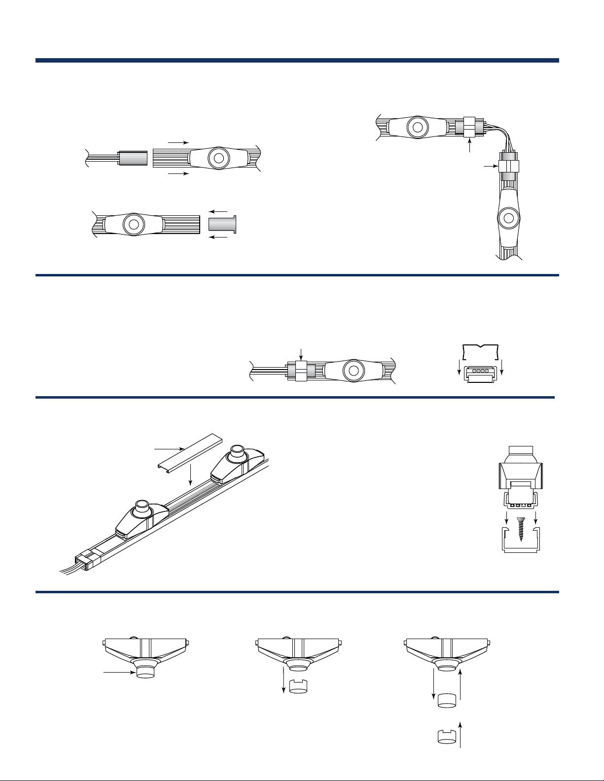
Step 3: Insert Feed Connector and End Cap
Feed Connector
Feed Connectors bring power to one end of a Tracklight run. Up
to 60 LED Modules can be powered from a single connector.
Do Not Snap Connectors in place
from above. Slide in place.
Do Not Snap End Caps in place
from above. Slide in place.
Step 4: Attach Retainer Clips
Retainer Clips
Retainer clips are included with Feed
Connectors and Flex Connectors.
These snap onto the xture to provide
a secure connection.
Feed Connector Assembled
Retainer Clips
Step 3A: Insert Flex Connector
(if required)
Retainer
Clips
Flex Connector
Assembled
Retainer Clips snap in
place from above.
Step 5: Cut Spacer to size and insert between
LED Modules.
Spacer
Lens Replacement
Snoot
Remove Snoot
Step 6: Install mounting clamps
Mounting Clamp
Mounting clamps are attached
with screws and the Micro
Tracklight xture is snapped in
place. Recommended spacing is
every 12".
Mounting Clamp
Remove Lens Insert New Lens
To replace a lens: Remove the Snoot then gently tap the LED module on a
hard surface and the lens will pop out. Insert new lens and re-insert Snoot.
Re-insert Snoot
Page 3
Micro Tracklight Installation Instructions Page 3
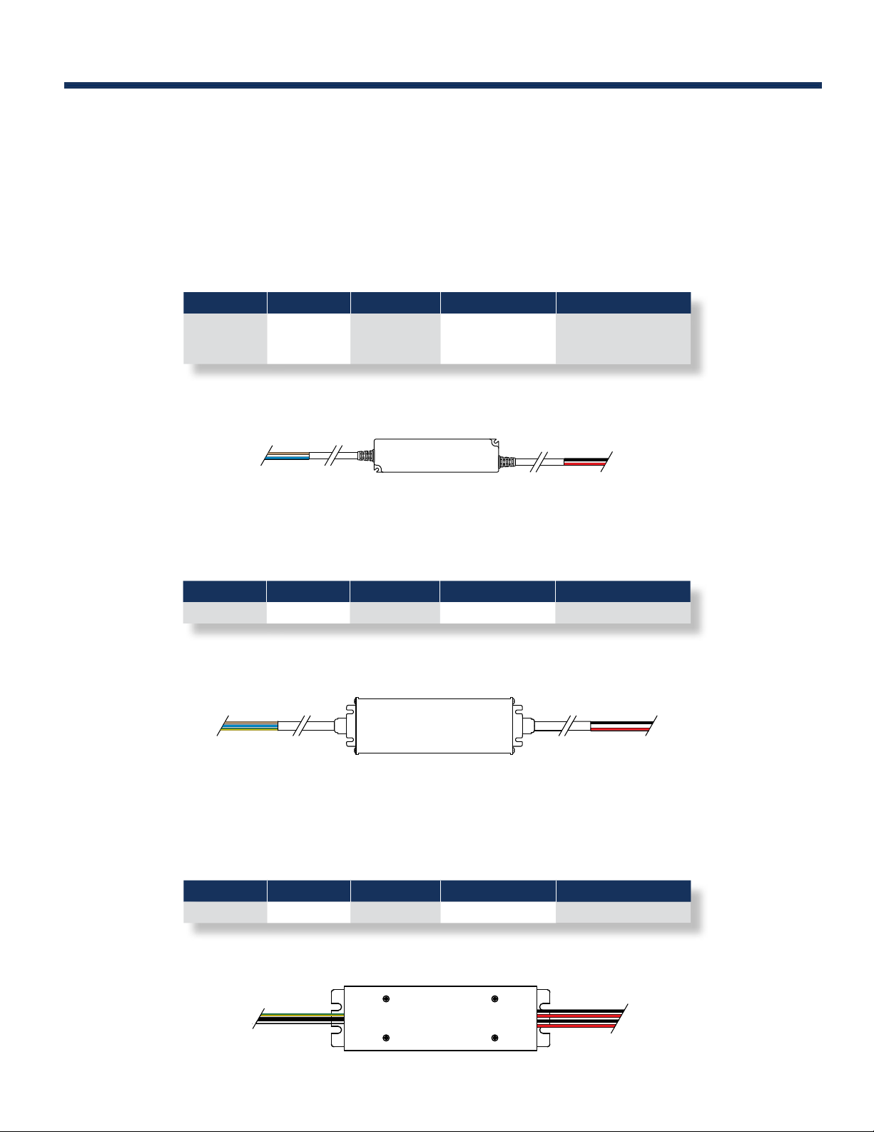
24 VDC LED Drivers
Micro Tracklight is ETL Listed when operated from our selection of 24 VDC LED Drivers. These Class 2
power supplies range from 16 to 192 watts. The input is universal ranging from 100 to 277 VAC 50/60 Hz.
LED Driver Installation
LDR24-16 (16 Watts) / LDR24-25 (25 Watts) / LDR24-40 (40 Watts)
These Class 2 LED Drivers convert an AC input into a 24 VDC output. Refer to the manual provided with
the LED Driver for detailed installation instructions.
Part# Input Volts Output Volts Output Ratings Capacity
LDR24-16
LDR24-25
LDR24-40
100~277 VAC Input (North America Only)
100~240
100~240
100~240
100~240 VAC Input
Brown Wire: AC Line
Blue Wire: AC Neutral
24 VDC
24 VDC
24 VDC
1 @ 0.67 Amps
1 @ 1.05 Amp
1 @ 1.67 Amps
24 VDC Output
Black Wire: -V
Red Wire: +V
10 LED Modules
15 LED Modules
25 LED Modules
LDR24-16 / LDR24-25 / LDR24-40 LED Drivers
LDR24-96
This 96 Watt Class 2 LED Driver converts an AC input into a 24 VDC output. Refer to the manual provided
with the LED Driver for detailed installation instructions.
Part# Input Volts Output Volts Output Ratings Capacity
LDR24-96 100~240 24 VDC 1 @ 4.0 Amps 60 LED Modules
100~277 VAC Input (North America Only)
100~240 VAC Input
Brown Wire: AC Line
Blue Wire: AC Neutral
Yellow/Green Wire: Ground
LDR24-96 LED Driver
24 VDC Output
Black Wire: -V
Red Wire: +V
LDR24-192
Tokistar’s LDR24-192 has two independent 96 watt outputs. This unit has wiring compartments for splicing on
input and output leads, and can be connected directly to conduit. Refer to the manual provided with the LED
Driver for detailed installation instructions.
Part# Input Volts Output Volts Output Ratings Capacity
LDR24-192 100~277 24 VDC 2 @ 4.0 Amps 120 LED Modules
100~277 VAC Input
Yellow/Green Wire: Ground
Black: AC Line
White: AC Neutral
24 VDC Output
Black Wire: -V
Red Wire: +V
Black Wire: -V
Red Wire: +V
LDR24-192 LED Driver
Page 4
Micro Tracklight Installation Instructions Page 4
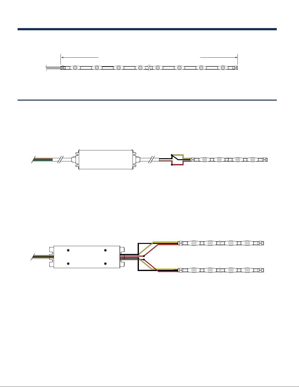
Secondary Circuit Wiring
Do Not Exceed LED Driver Capacity / Maximum 96 watts
Non-Dimming Wiring Details
Single Output LED Driver
100~240 VAC Input
Brown: AC Line
Blue: AC Neutral
Yellow/Green Wire: Ground
LDR24-96 LED Driver
Secondary Circuit Limit
24 VDC Output
Black Wire: -V
Red Wire: +V
Yellow Wire: -V
Black Wire: -V
Red Wire: +V
Micro Tracklight
Dual Output LED Driver
100~277 VAC Input
Yellow/Green Wire: Ground
Black Wire: AC Line
White Wire: AC Neutral
LDR24-192 LED Driver
24 VDC Output
Black Wire: -V
Red Wire: +V
Black Wire: -V
Red Wire: +V
Yellow Wire: -V
Black Wire: -V
Red Wire: +V
Yellow Wire: -V
Black Wire: -V
Red Wire: +V
Micro Tracklight
Micro Tracklight
Page 5
Micro Tracklight Installation Instructions Page 5
Dimming Micro Tracklight
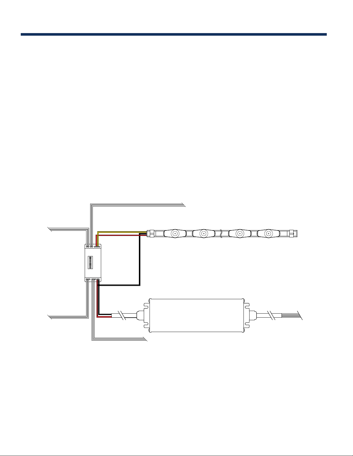
LC-1CH-MULTI Dimming System
Dimmer Pack - Part #: LC-1CH-MULTI
Each dimmer pack receives 24 VDC from an LED Driver. The LDR24-192 LED Driver has two independent 96 watt
outputs. Each output requires an independent dimmer pack.
DMX Mode - Each unit is independently addressable. Up to 36 dimmer packs may be connected in series. For
applications exceeding 36 dimmer packs, an additional feed from the DMX dimmer is required. The additional feed(s)
can be sent directly from the dimmer, or you may use DMX Splitters. Consult factory on details of DMX Splitters
Analog Modes - For operation from devices using 0/1-10 VDC protocol, up to 10 dimmer packs may be connected in
series. For applications exceeding 10 dimmer packs, an additional feed from the analog dimming device is required.
Manual Mode - You may select a light intensity the xtures will operate at. In this case, no external dimming device
is required.
For further information, refer to the instruction manual provided with the LC-1CH-MULTI Dimmer Pack.
.
0/1-10 VDC In
DMX In
0/1-10 VDC to next Dimmer Pack
24 VDC Output
Yellow Wire: PWM Signal
Red Wire: +V
Dimmer
Pack
Black Wire: -V
24 VDC Input
Black Wire: -V
Red Wire: +V
DMX next Dimmer Pack
Micro Tracklight
100~240 VAC Input
LED Driver
Page 6
Micro Tracklight Installation Instructions Page 6
Dimming Micro Tracklight
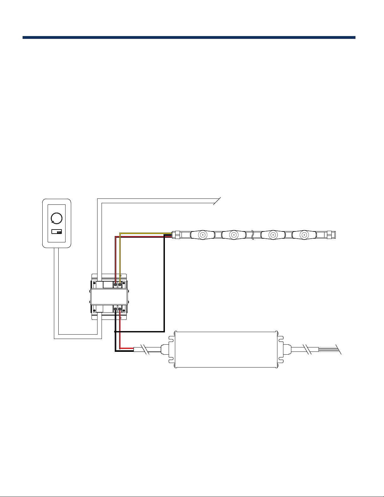
LC Dimming System
Wall Dimmer - Part #: LC-DMR
Power to the remote wall dimmer is provided from the LED Driver powering the rst Dimmer Pack. A 50 foot
CAT5 cable is provided.
Dimmer Pack - Part #: LC-1CH-DP
Each dimmer pack receives 24 VDC from an LED Driver. The LDR24-192 LED Driver has two independent
96 watt outputs. Each output requires an independent dimmer pack. A CAT5 cable is provided with each unit.
Up to 25 dimmer packs may be connected in series if the total length of all CAT5 cable does not exceed 165 feet
from the wall dimmer to the last dimmer pack.
For further information, refer to the instruction manual provided with the LC-1CH-DP.
LC-DMR
Dimmer
Signal to next Dimmer Pack
24 VDC Output
Yellow Wire: PWM Signal
Red Wire: +V
Dimmer
Pack
-V +V
24 VDC Input
Black Wire: -V
Red Wire: +V
Micro Tracklight
Black Wire: -V
100~240 VAC Input
LED Driver
TOKISTAR® LIGHTING
1015 E. Discovery Lane
Anaheim, CA 92801
TEL: 714 772 7005 FAX: 714 772 7014
email: [email protected] Website: tokistar.com
Version 1.2
 Loading...