

Tokistar Advantage AVLED-KC, Advantage AVLED-LW, Advantage Series, Advantage AVLED-WW, Advantage AVLED-IW Instruction Manual
...
TOKISTAR LIGHTING
24/5
INSTRUCTION MANUAL
Advantage Series
General Description
Tokistar’s Advantage Series is a 24 VAC lighting system using LED modules or rigid-loop xenon lamps. LEDs are
0.72 watts. Xenon lamps are available at 3 watt and 5 watt. Xenon lamps have the voltage and rating stamped on the
glass at one end. Each Advantage xture is labeled with wattage and operating voltage.
The voltage and lamp rating are stamped
on one end of the xenon lamps.
Light Source
Description Part No.
0.72 Watt LED
0.72 Watt LED
0.72 Watt LED
0.72 Watt LED
3 Watt Xenon
5 Watt Xenon
AVLED-KC
AVLED-LW
AVLED-WW
AVLED-IW
XB-3F
XB-5F
Wire
Socket
Side View
LED Module
Wire
Wire
Xenon Lamp
Socket
Wire
Side View
Secondary Circuit Limitation
The maximum load of each xture must not exceed 480
Watts (20 amps @ 24 Volts). In addition to this limitation,
Secondary Circuit Limitation
Each secondary circuit MUST NOT exceed
20 amps (480 watts @ 24VAC)
consideration must be given to the effects of voltage drop.
Fixtures with lower wattage lamps (such as LEDs) and
more distant socket spacing have recommended maximum
T
lengths less than 480 Watts.
This chart gives recommended
maximum lengths which take into
account these two limitations.
Conforming to these lengths will
ensure no xture exceeds 480
Watts, and will not be subjected to
Maximum Lamps/Circuit 160 Lamps 96 Lamps 400 LEDs
Lamp Spacing Maximum Run Lengths
2.4" O.C. (60 mm)
3" O.C. (75 mm)
4" O.C. (100 mm)
6" O.C. (150 mm)
3 Watt/X3 5 Watt/X5 0.72 Watt LED Modules
32' (9.6 M)
40' (12 M)
48' (14.4 M)
60' (18 M)
19' (5.76 M)
24' (7.2 M)
32' (9.6 M)
48' (14.4 M)
excessive voltage drop.
PRECAUTIONS
1. Read all instructions completely before beginning installation.
2. Turn off electricity before beginning installation.
3. All wiring is to be performed by a qualied electrician.
4. Installation must comply with the National Electrical Code, and all applicable codes.
5. Turn main supply to transformer on only after all connections are made and tested.
6. Use only transformers provided by Tokistar with the system.
80' (24 M)
100' (30 M)
133' (40 M)
200' (60 M)
TOKISTAR LIGHTING
1015 E. Discovery Lane
Anaheim, CA 92801
TEL: 714 772 7005 FAX: 714 772 7014
email: info@tokistar.com Website: tokistar.com
Version 1.1
Advantage Instructions Page 2
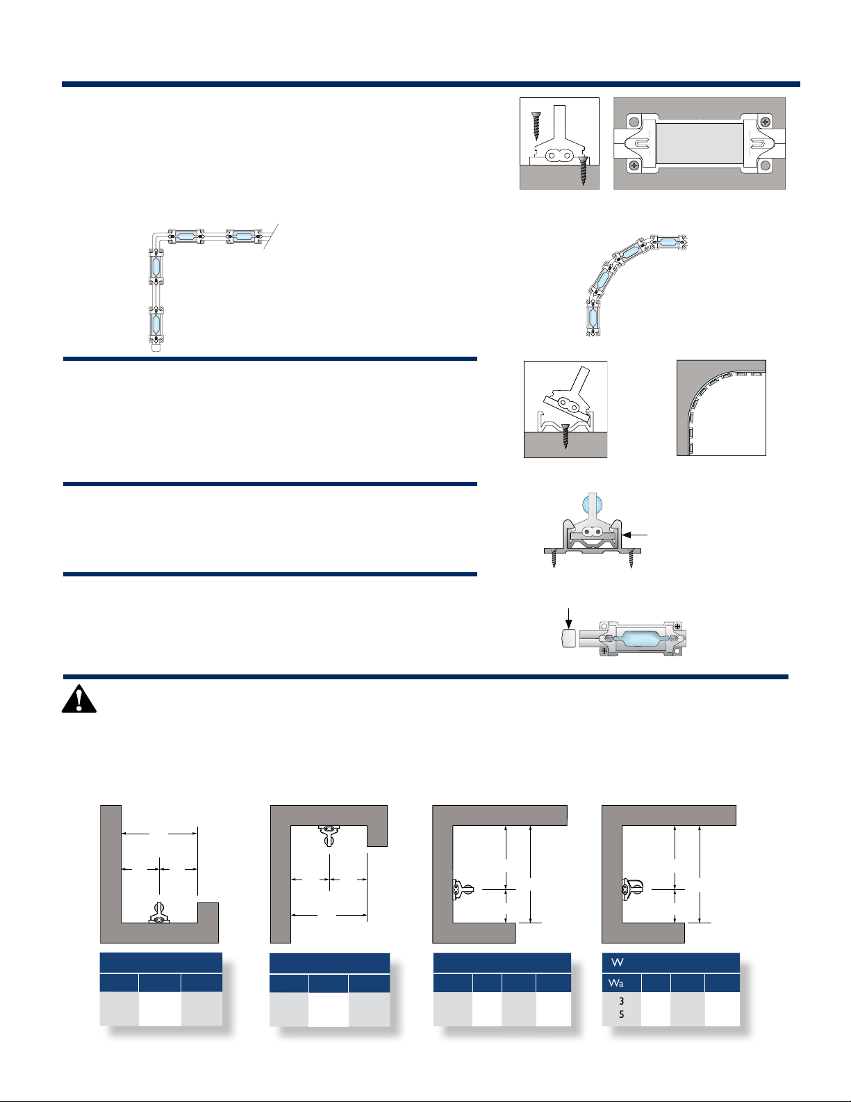
Step 1: Mounting Fixtures
Option 1 - Direct Screw Mounting (Part# AV-MS)
Each LED or lamp socket, has four mounting holes designed to accept
screws. For secure mounting, use two screws in opposing holes. Sockets
must be rmly attached to support the weight of the xture.
3", 4" and 6" socket spacing
Seamless Light
Advantage xtures are exible enough to turn
corners without the use of special hardware,
eliminating dark spots at corner locations.
Option 2 - Mounting Channel (Part# AV-MC)
An optional mounting channel may have been provided with your
materials. Screw the channel securely in place, then snap each socket
into the channel. Attach screws every 8".
Option 2A - Channel Clamps (Part# AV-CL)
These clamps are for use with our AV-MC Mounting Channel. Screw the
clamps securely in place, then snap in the channel. Attach clamps every 8".
End Caps - Part# ECD-WH (White) / Part# ECD-BK (Black)
Ends caps are attached to the end of each Advantage lighting xture. If the
xture needs to be trimmed, a new end cap needs to be attached to the end
of the xture after trimming.
2.4" socket spacing
Attach screws
every 8"
End Cap
Mounting Channel
conforms to a 24" inside
or outside radius.
Channel Clamp
PRECAUTIONS / Heat Consideration
Xenon lamps produce heat and will cause damage if they come in direct contact with persons or combustible
materials. In accordance with NEC/NFPA 70 Article 410.11, combustible materials next to xtures must not be
subjected to temperatures in excess of 90º C (194º F). In order to conform to this standard, xtures need to be
installed according to the minimum space requirements shown below.
D
d
d
Basic System 2.4" O.C.
Watts d D
3
.75"1"1.5"
5
2"
d
d
D
Basic System 2.4" O.C.
Watts d D
3
1"
5
1.5"2"3"
d1
D
d2
Basic System 2.4" O.C.
Watts d1 d2 D
351"
1.5"
.75"1"1.75"
2.5"
With Reector 2.4" O.C.
Watts d1 d2 D
35.75"
.75"
d1
d2
.75"
1.25"
D
1.5"
2"
 Loading...