

Page 1

WWC T1
Calculator
Set Up & Maintenance
Manual
Document Ref 905675-001
Rev - 2
01/2006
Page 2

WWC T1 Set Up & Maintenance Manual
Great care has been taken in the preparation of this manual however T okheim
shall not be liable for any misunderstanding, errors and/or loss or defect
arising from the use of this manual.
Tokheim shall not be liable for damage to the product, nor for personal or
third party injury, caused by incorrect use of the product or by attempts to
maintain or to repair the product by parties other than those fully trained by
Tokheim or by its accredited third party representatives.
Please contact your nearest service department, at the relevant address
printed on the back cover of this manual, should any aspect of this manual
be unclear.
© Copyright by Tokheim. All intellectual rights arising from, accruing
to,and residing in this manual belong to Tokheim. No part of this
document may be reproduced in any form without the express written
permission of Tokheim.
Tokheim reserves the right to apply changes to this document and the
equipment without further notice.
Issue A
Document Ref 905675-001 Rev 2
Page 3

WWC T1 Set Up & Maintenance Manual Revision Record
REVISI ON RECORD
Date Revision Page Issue Reason
01/07/2004 1 All A Original Issue
19/01/2006 2 3 to 6 B Main Contents revised
19/01/2006 2 2-16,2-17 B Updated Func tionalities
19/01/ 2006 2 2-21 to 2-23 B New info added (Input Type, Mast er PIN Code, Gallon
Type, Cent Overshoot Hide, 4 position product indicator,
Heavy Lei); repagination
19/01/ 2006 2 3-1 B Sec tion 3 Contents revised
19/01/2006 2 3-6,3-7 B Headings changed
19/01/ 2006 2 5-1 B Sec tion 5 Contents revised
19/01/2006 2 5-4 to 5-16 B New info added (Cent Overs hoot Hide, 4 pos ition
product indicator, Heavy Lei); repagination
19/01/ 2006 2 6-1 B Sec tion 6 Contents revised
19/01/ 2006 2 6-8,6-9 B New info added (Heavy Lei)
19/01/2006 2 6-15 to 6-42 B New info added (Cent Overshoot Hide, 4 position
product indicator); repagination
19/01/ 2006 2 7-1 B Sec tion 7 Contents revised
19/01/2006 2 7-3 B New information added (Vapour Mes menu)
19/01/2006 2 7-7,7-8 A New pages inserted, new information added (Tokheim
protocol
19/01/2006 2 11-4 B New info added (max time no flow)
19/01/2006 2 12-2,12-3 B New options added to POM
Document Ref 905675-001 Rev 2 1
Page 4

Revision Record WWC T1 Set Up & Maintenance Manual
This page is intentionally blank
Issue A
2 Document Ref 905675-001 Rev 2
Page 5

WWC T1 Set Up & Maintenance Manual Contents
CONTENTS
1 INTRODUCTION......................................................................................................... 1-2
1.1 How to Use this Manual ..................................................................................... 1-2
1.2 Product Scope ..................................................................................................... 1-3
1.3 Authorised Technicians....................................................................................... 1-3
1.4 Contact Information ............................................................................................ 1-3
1.5 Health & Safety .................................................................................................. 1-3
1.5.1 Safety Checklist.................................................................................. 1-3
1.5.2 Duties of the Employees..................................................................... 1-4
1.5.3 Hazards ............................................................................................... 1-4
1.5.4 Warning Signs .................................................................................... 1-5
1.5.5 Personal Protective Equipment (PPE) ................................................ 1-6
1.6 Nomenclature ...................................................................................................... 1-7
2 PRODUCT INFORMATION....................................................................................... 2-2
2.1 System Description ............................................................................................. 2-2
2.1.1 Operating Principles ........................................................................... 2-2
2.2 Main Components of the WWC ......................................................................... 2-2
2.2.1 External Power Supply ....................................................................... 2-3
2.2.2 Mainboard .......................................................................................... 2-3
2.2.3 I/O Board (version 3++) ..................................................................... 2-4
2.2.4 Transaction Displays .......................................................................... 2-4
2.2.5 User Access Devices (UAK/UAM).................................................... 2-4
2.3 Different Configurations ..................................................................................... 2-4
2.3.1 Standard dispensers with up to four single products.......................... 2-5
2.3.2 Low-end dispensers : single product or twin configuration, super
high speed, single-sided (Fleet).......................................................... 2-5
2.3.3 Vapour Recovery Controller Board (VRC) ........................................ 2-6
2.3.4 Option Controller Board (OCB) ......................................................... 2-6
2.3.5 Hydraulic Option Modules (HOM) .................................................... 2-6
2.3.6 I/O Extension Board (IEB) ................................................................. 2-6
2.4 Product Option Matrix (POM)............................................................................ 2-6
2.5 Functionality ....................................................................................................... 2-6
2.5.1 Functionalities per hose...................................................................... 2-7
2.5.2 Functionalities per side .................................................................... 2-10
2.5.3 Functionalities per dispenser ............................................................ 2-16
2.5.4 Weights & Measures related Functionality ...................................... 2-21
Issue B
3 LPG SET UP .................................................................................................................. 3-2
3.1 LPG Functionality............................................................................................... 3-2
3.1.1 LPG Pulse Menu ................................................................................ 3-2
3.1.2 LPG Nozzle Flag Menu ...................................................................... 3-2
3.1.3 LPG Delay Timer Menu ..................................................................... 3-3
3.1.4 LPG Motor Off Timer Menu.............................................................. 3-3
3.2 LPG Hydraulic Functions ................................................................................... 3-4
3.2.1 Valves ................................................................................................. 3-4
3.2.2 Hydraulic Schematic .......................................................................... 3-5
3.3 Timing Diagrams ................................................................................................ 3-6
3.3.1 Timing with Nozzle Switch & Motor Off Delay
≠≠
≠ 0 ......................... 3-6
≠≠
3.3.2 Timing with Nozzle Switch & Motor Off Delay = 0 ......................... 3-6
(CONT.)
Document Ref 905675-001 Rev 2 3
Page 6

Contents WWC T1 Set Up & Maintenance Manual
3 LPG SET UP /
3.3.3 Timing with Deadmans Button only & Motor Off Delay
3.3.4 Timing with Deadmans Button only & Motor Off Delay = 0 ............ 3-7
4 SERVICE KEYPAD...................................................................................................... 4-2
4.1 User Access Keypad (UAK) ............................................................................... 4-2
4.2 Infra Red (IR) Remote Control Keypad.............................................................. 4-4
4.3 Internal Configuration Keypad ........................................................................... 4-4
5 SET UP MODE.............................................................................................................. 5-2
5.1 General ................................................................................................................ 5-2
5.2 Start Ups ............................................................................................................. 5-2
5.2.1 Cold Start............................................................................................ 5-2
5.2.2 Warm Start.......................................................................................... 5-3
5.2.3 Service Start ....................................................................................... 5-3
5.3 Initial Set Up Menu............................................................................................. 5-3
5.3.1 Set up Function Overview .................................................................. 5-4
5.3.2 Set Up Menu....................................................................................... 5-5
5.4 AFM Set Up Menu ........................................................................................... 5-10
5.4.1 No Address Conflict ......................................................................... 5-10
5.4.2 Address Conflict ............................................................................... 5-14
5.4.3 AFM Addresses ................................................................................ 5-16
≠≠
≠ 0 ............ 3-7
≠≠
6 MAINTENANCE MODE............................................................................................. 6-2
6.1 General ................................................................................................................ 6-2
6.2 Maintenance Function Overview ........................................................................ 6-2
6.3 Access the Maintenance Functions..................................................................... 6-4
6.4 Exit Maintenance Mode...................................................................................... 6-5
6.5 Diagnostic Information (Error Log) ................................................................... 6-6
6.5.1 Kernel versions > 01.07 ..................................................................... 6-6
6.5.2 Kernel versions <= 01.07 ................................................................... 6-7
6.6 Leak Tests ........................................................................................................... 6-8
6.7 Country Code, Euro and Application Set Up...................................................... 6-8
6.8 LPG Functionality............................................................................................. 6-10
6.9 Thermal Protection Reset .................................................................................. 6-11
6.9.1 Kernel versions > 01.07 ....................................................................6-11
6.9.2 Kernel versions <= 01.07 ..................................................................6-11
6.10 Leak Detection Functionality............................................................................ 6-12
6.10.1 Vapour Leak Detection (France only) .............................................. 6-12
6.10.2 Flow Protection Reset (AFM Leak Detection) ................................ 6-12
6.10.3 Esso Leak Detection......................................................................... 6-13
6.11 Fraud Detection Functionality .......................................................................... 6-13
6.12 Combined Hose Pre-selection and Display Timeout ........................................ 6-14
6.13 Electro-Mechanical Totaliser Mode (EMT) Functionality ............................... 6-14
6.14 Cent Overshoot Hide Functionality .................................................................. 6-15
6.15 Q500T1 Four Position Product Indicator ......................................................... 6-15
6.16 Stop/Off Switch ................................................................................................ 6-16
6.17 Fuel Leak Detection.......................................................................................... 6-16
6.17.1 Set Up PIN Code (Fuel Leak Detection only).................................. 6-17
6.18 Blend Ratio ....................................................................................................... 6-17
6.19 Local Preset Values ........................................................................................... 6-18
Issue B
(CONT.)
4 Document Ref 905675-001 Rev 2
Page 7

WWC T1 Set Up & Maintenance Manual Contents
6 MAINTENANCE MODE /
6.20 Node Address .................................................................................................... 6-18
6.21 Test Delivery..................................................................................................... 6-19
6.22 Emergency Manual Pumping Device (EMPD)................................................. 6-21
6.23 Product Relation ............................................................................................... 6-21
6.23.1 Product Name by Character Input .................................................... 6-22
6.23.2 Product Name from Pick List ........................................................... 6-23
6.24 Vapour Recovery............................................................................................... 6-24
6.24.1 Kernel versions <= 0.???.................................................................. 6-24
6.25 Vapour Delay .................................................................................................... 6-25
6.26 Pump Motor Delay (Submerged/Remote pumps only)..................................... 6-25
6.27 Optional Preset Valve........................................................................................ 6-26
6.28 Valve Reponse Value ........................................................................................ 6-26
6.29 AFM Menu ....................................................................................................... 6-27
6.29.1 AFM change menu ........................................................................... 6-27
6.29.2 AFM Read-only menu ...................................................................... 6-27
6.30 Product Position................................................................................................ 6-29
6.31 Option Selection ............................................................................................... 6-30
6.31.1 IEB (I/O Extension Board) Options ................................................. 6-30
6.31.2 OCB (Option Controller Board) Options ......................................... 6-31
6.32 Nozzle Sensor Definition.................................................................................. 6-37
6.32.1 Kernel version >= 03.08................................................................... 6-37
6.32.2 Kernel version >= 03.03................................................................... 6-37
6.32.3 Kernel version >= 02.12................................................................... 6-40
6.32.4 Kernel version < 02.12 ..................................................................... 6-42
Issue B
7 APPLICATION MODE................................................................................................ 7-2
7.1 All Applications .................................................................................................. 7-2
7.2 EPS...................................................................................................................... 7-3
7.3 IFSF..................................................................................................................... 7-4
7.4 ZSR ..................................................................................................................... 7-5
7.5 Dunclare .............................................................................................................. 7-6
7.6 Tokheim .............................................................................................................. 7-7
8 PIN CODES ................................................................................................................... 8-2
8.1 First PIN code ..................................................................................................... 8-2
8.2 Change PIN code ................................................................................................ 8-3
9 TOTALS ......................................................................................................................... 9-2
9.1 Reading the Totals (Amount, Volume & Number of Deliveries) ....................... 9-2
10 UNIT PRICES ............................................................................................................. 10-2
10.1 Set/Change Unit Prices ..................................................................................... 10-2
11 INSPECTION FUNCTIONS ......................................................................................11-2
11.1 Inspection Function Overview ...........................................................................11-2
11.2 General...............................................................................................................11-3
11.3 Delivery Mode ...................................................................................................11-3
11.4 Traffic Lights .....................................................................................................11-3
11.5 Idle Display Control...........................................................................................11-3
11.6 Satellite Control .................................................................................................11-3
(CONT.)
Document Ref 905675-001 Rev 2 5
Page 8

Contents WWC T1 Set Up & Maintenance Manual
11 INSPECTION FUNCTIONS /
11.7 Release Management .........................................................................................11-4
11.8 Maximum Time for a Filling .............................................................................11-4
11.9 Time Between Two Fillings ...............................................................................11-4
11.10 Maximum Time of No Flow ..............................................................................11-4
11.11 Maximum Time a Filling can be Suspended .....................................................11-5
11.12 Timer for Display TImeout................................................................................11-5
11.13 Delivery Fraud Timer.........................................................................................11-5
11.14 Software Versions ..............................................................................................11-5
11.15 Pulser Hide.........................................................................................................11-8
11.16 Preset Totalisers .................................................................................................11-8
12 APPENDIX .................................................................................................................. 12-2
12.1 Appendix A - Product Option Matrix ............................................................... 12-2
12.2 Appendix B - Country Codes............................................................................ 12-4
12.3 Appendix C - Error Codes ................................................................................ 12-6
12.3.1 Startup Error Situations.................................................................... 12-6
12.3.2 Displaying Error Messages .............................................................. 12-6
12.3.3 Diagnostic Database ......................................................................... 12-7
12.4 Appendix D - Jumper Positions ...................................................................... 12-10
12.4.1 Mainboard ...................................................................................... 12-10
12.4.2 VRC Board ......................................................................................12-11
12.4.3 User Access Module ....................................................................... 12-12
12.4.4 OCB Board ..................................................................................... 12-13
12.4.5 I/O Extension Board (IEB)............................................................. 12-14
12.4.6 Hydraulic Option Module (HOM) ................................................. 12-14
12.4.7 Axial Flow Meter Measurement Solution (AFM) ......................... 12-14
12.5 Appendix E - General Purpose Inputs ............................................................ 12-15
12.6 Appendix F- IEB General Purpose Outputs.................................................... 12-16
6 Document Ref 905675-001 Rev 2
Issue B
Page 9

WWC T1 Set Up & Maintenance Manual Introduction
CONTENTS
1 INTRODUCTION........................................................................................................ 1-2
1.1 How to Use this Manual ......................................................................................1-2
1.2 Product Scope ......................................................................................................1-3
1.3 Authorised Technicians ........................................................................................1-3
1.4 Contact Information .............................................................................................1-3
1.5 Health & Safety ...................................................................................................1-3
1.5.1 Safety Checklist ...................................................................................1-3
1.5.2 Duties of the Employees......................................................................1-4
1.5.3 Hazards................................................................................................1-4
1.5.4 Warning Signs ......................................................................................1-5
1.5.5 Personal Protective Equipment (PPE) ................................................1-6
1.6 Nomenclature .......................................................................................................1-7
Issue A
Document Ref 905675-001 Rev 2 Page 1-1
Page 10

Introduction WWC T1 Set Up & Maintenance Manual
1 INTRODUCTION
1.1 How to Use this Manual
It is recommended that all relevant persons familiarise themselves with the contents of this
manual prior to carrying out any operations or procedures.
This manual is divided into sections which are described as follows: -
Section 1 - Introduction
This section contains information on how to use the manual, the scope of equipment covered,
recommendations on qualified technicians and contact information. It also includes relevant
health and safety information and certification relating to the product.
Section 2 - Product Information
This section contains the system description and operating principles of the WWC T1
Calculator. It also describes the main components, their configurations and functions
including the service keypads.
Section 3 - LPG Specification
All additional information relating to LPG options is contained in this section.
Section 4 - Service Keypad
This section describes the functions of the various keypads.
Section 5 - Set Up Modes
This section provides instructions for cold start, warm start and service start of the product.
Section 6 - Maintenance Mode
All aspects relating to the maintenance of the equipment are covered in this section.
Section 7 - Application Mode
This section contains information on the EPS, IFSF and ZSR Application Modes.
Section 8 - PIN Code
This section contains information on how to change the PIN code.
Section 9 - Totals
Instructions on how to read totals is contained in this section.
Section 10 - Unit Prices
This section contains information on setting and changing the Unit Prices.
Section 11 - Inspection Functions
All information relating to the Inspection Function is contained in this section.
Section 12 Appendices
This section contains the appendices.
Page 1-2 Document Ref 905675-001 Rev 2
Issue A
Page 11

WWC T1 Set Up & Maintenance Manual Introduction
1.2 Product Scope
This manual is designed to cover the Quantium T range of dispensers including LPG. As
functionality is equivalent to the Coca 1.1 functionality , reference is frequently made to the
existing Coca Manuals.
1.3 Authorised Technicians
Only qualified technicians familiar with the contents of this manual should carry out the
procedures contained herein.
WARNING : ANY ATTEMPTS TO CARRY OUT THE PROCEDURES OF THIS
MANUAL, BY UNQUALIFIED OR UNAUTHORISED PERSONS, MAY
RESULT IN SERIOUS INJURY OR LOSS OF LIFE.
Note : This manual is not intended to replace the services of a fully qualified
technician.
1.4 Contact Information
For information relating to the contents of this manual please contact: T echnical Author
Tokheim UK Ltd.
Dundee, Scotland
For technical assistance please contact the appropriate service division listed on the back
cover of this manual.
1.5 Health & Safety
1.5.1 SAFETY CHECKLIST
•It is obligatory that this checklist be fully complied with during all work at the
petrol station, particularly construction or repair work.
•It is the duty of the contractor to ensure that all workers employed by him obey
each and all of the relevant laws, directives and other regulations.
Areas where special caution is required
•The insides of tanks, tubes, dome shafts, filling shafts, change over shafts, vessels
and dispensers.
•All areas in which fuel vapour that is heavier than air can accumulate, e.g. fuel
separator, draining shafts, low located rooms, cellars, excavations, pipe trenches
etc.
Issue A
•The areas around the outlets of tank ventilation pipes, especially during the filling
phase.
•All areas near dispensers, tanker lorries and other vehicles while they are being
tanked up, and particularly when there is a lack of wind.
•A radius of 1.0 metres around petrol carrying pipes, as well as pipes that are not
vapour free.
•Silt traps.
Document Ref 905675-001 Rev 2 Page 1-3
Page 12

Introduction WWC T1 Set Up & Maintenance Manual
1.5.2 DUTIES OF THE EMPLOYEES
•To ensure optimal accident prevention in our company, in addition to general
rules applying to worker’s protection, it is necessary to take into account all the
national protection of workers legislation and to actively support all measures
which enhance safety standards.
•It is an employee’s duty to follow all company directives regarding the prevention
of accidents, unless such directives can be proved to be unfounded.
•Employees should not follow any instructions that go against safety standards.
•Employees are only permitted to use equipment for its original purpose, and this
is defined by the company alone.
•If an employee detects equipment that is deficient in terms of safety, he shall
eliminate this deficiency immediately . If such safety rectification is not part of
his defined area of activities, or if his knowledge is insufficient to carry out such
work he must immediately inform his superior about the detected safety
deficiency.
This equally applies to:
1) Work Materials which have not been correctly packed or correctly marked in
order to meet safety requirements.
2) Work Methods or work processes which have not been correctly coordinated
or controlled in order to meet safety requirements.
3) Where dangerous activities are carried out by several persons, the need
for a permanent faultless communication between them in order to avoid
dangerous events shall require the appointing of one person in order to carry out
overall supervision.
1.5.3 HAZARDS
Prior to starting work, the dispenser must be isolated (i.e. entirely disconnected
from the mains supply) and the mains supply switch locked in the OFF position.
The submerged pump (if applicable) and control signals from the dispenser must
also be isolated. This is done to provide safety for the technician. As a further
precaution, switch off the mains supply in the service station shop and place a
clear notice on the switch to avoid it being turned on again inadvertently.
WARNING : THE CONNECTION AND DISCONNECTION OF
ELECTRICAL CONNECTIONS MAY ONLY BE CARRIED OUT BY
QUALIFIED PERSONNEL AUTHORISED FOR SUCH ACTIVITIES.
WORK IN DANGEROUS AREAS MUST BE MADE SAFE BY
OBSERVING ALL THE NATIONAL SAFETY REQUIREMENTS IN
FORCE.
It is not permitted to put a fuel dispenser into operation before an authorised
official has inspected it and released it. This depends upon the national regulations
in force.
Issue A
Dismantled packaging and cladding must be stored in such a way as to avoid
damage to components or injuries to persons. Covers that can be opened, such
as the calculator housing, should be handled with care. Ensure that the retaining
catch is placed in the correct position to prevent the cover falling onto the head
of the service engineer or other persons in the area.
Page 1-4 Document Ref 905675-001 Rev 2
Page 13
WWC T1 Set Up & Maintenance Manual Introduction
At unattended service stations, every end-user should be able to read the User
Instructions. They should be visible on a notice board or integrated into the DIT
and should be sufficiently well lit so that they can be read at night.
At unattended service stations break away couplings must always be used to
reduce the danger caused by a motorist driving off with the nozzle still in the
tank.
1.5.4 WARNING SIGNS
The following warning signs are fitted as standard, on the dispenser, however
they may vary according to individual country requirements or customer
specifications.
SIGN
MEANING POSITION
Do not use mobile
phones
Naked flames and
smoking forbidden
Do not spill fuel on the
ground
Stop vehicle engine
Visible from both
sides of dispenser
Visible from both
sides of dispenser
Visible from both
sides of dispenser
Visible from both
sides of dispenser
Issue A
At Diesel high speed
Trucks only
dispensers near the
nozzle boots
Do not drive away with
nozzle in tank
Visible from both
sides of dispenser
Next to User
Instructions near the
nozzle boot
Document Ref 905675-001 Rev 2 Page 1-5
Page 14

Introduction WWC T1 Set Up & Maintenance Manual
1.5.5 PERSONAL PROTECTIVE EQUIPMENT (PPE)
PROTECTIVE CLOTHING
The following clothing should be worn at all times during installation and
maintenance procedures:-
•Protective helmet.
•Protective shoes (conductive).
•Protective gloves and/or protective hand cream.
•Anti static clothing.
•Eye protection.
SAFETY EQUIPMENT FOR WORKING IN HAZARDOUS AREAS
The following safety equipment is required for working in hazardous areas:-
•Only spark free tools are permitted for work on dispensers.
•Work on bearings is only permitted using the standard workshop tools authorised
for this kind of work.
•The use of all electrical tools is strictly prohibited.
•Only the use of explosion protected work lights is permitted.
•The use of telecommunications equipment in hazardous areas is strictly prohibited.
SAFETY INSTRUCTIONS
The following safety instructions must be adhered to during installation and
maintenance procedures:-
•Inhalation of petrol vapour must be avoided. Suitable precautions must be taken
and where necessary respirators used.
•Avoid direct contact of fuel with the skin.
•Use suitable protective clothing, protective gloves and/or protective hand cream.
•Avoid fuel spills.
•No smoking, no naked flames are permitted.
•Long hair and ties can get caught in moving parts. Hair must be suitably covered.
Page 1-6 Document Ref 905675-001 Rev 2
Issue A
Page 15

WWC T1 Set Up & Maintenance Manual Introduction
1.6 Nomenclature
The various abbreviations used in thie manual are described as follows:CoCa Today’s Common Calculator and base of the WWC
CSD-F Common Sales Display - Ferranti
CSD-L Common Sales Display - LCD
Dipnet Dispenser inter-peripheral network
ELU Energy Limiting Unit (i.e.Nozzle Bus Intrinsically Safe Barrier)
EMPD Emergency Manual Pumping Device
EMT Electro-Mechanical T otalizer
HCM Hydraulic Control Module
HOM Hydraulic Option Module
HSC Hall Sensor Controller
HVU High V oltage Unit
IEB I/O Extension Board
IFSF International Forecourt Standard Forum
IOB I/O Board
IRM Infra Red Module
LON Local Operating Network
MB251 Mainboard 80251
MP1 Magnetic Pulser 1
NBB Nozzle Bus Board (integrated in Main Board v3 and later)
OCB Option Controller Board
ODU Optional Display Board
OPB Option Peripheral Board
OPU Optional Peripheral Unit
PCB Printed Circuit Board
POS Point of Sale
SCG Self Calibrating Gas
SPI Serial Peripheral Interface
UA K User Access Keypad
Issue A
UAM User Access Module
UPD Unit Price Display
VFM V apour Flow Module
VRC V apour Recovery Controller
WWC W orld Wide Calculator
Document Ref 905675-001 Rev 2 Page 1-7
Page 16

Introduction WWC T1 Set Up & Maintenance Manual
This page is intentionally blank
Issue A
Page 1-8 Document Ref 905675-001 Rev 2
Page 17

WWC T1 Set Up & Maintenance Manual Product Information
CONTENTS
2 PRODUCT INFORMATION .................................................................................... 2-2
2.1 System Description ..............................................................................................2-2
2.1.1 Operating Principles.............................................................................2-2
2.2 Main Components of the WWC ..........................................................................2-2
2.2.1 External Power Supply ........................................................................2-3
2.2.2 Mainboard............................................................................................2-3
2.2.3 I/O Board (version 3++)......................................................................2-4
2.2.4 Transaction Displays............................................................................2-4
2.2.5 User Access Devices (UAK/UAM) ...................................................2-4
2.3 Different Configurations ......................................................................................2-4
2.3.1 Standard dispensers with up to four single products............................2-5
2.3.2 Low-end dispensers : single product or twin configuration, super high
speed, single-sided (Fleet)....................................................................2-5
2.3.3 Vapour Recovery Controller Board (VRC).........................................2-6
2.3.4 Option Controller Board (OCB) ..........................................................2-6
2.3.5 Hydraulic Option Modules (HOM)......................................................2-6
2.3.6 I/O Extension Board (IEB)..................................................................2-6
2.4 Product Option Matrix (POM).............................................................................2-6
2.5 Functionality .........................................................................................................2-6
2.5.1 Functionalities per hose........................................................................2-7
2.5.2 Functionalities per side.......................................................................2-10
2.5.3 Functionalities per dispenser ..............................................................2-16
2.5.4 Weights & Measures related Functionality........................................2-21
Issue A
Document Ref 905675-001 Rev 2 Page 2-1
Page 18

Product Information WWC T1 Set Up & Maintenance Manual
2 PRODUCT INFORMATION
2.1 System Description
The WWC (World Wide Calculator) is a ‘measuring system’ built to conform to the
international recommendations specified in the document OIML R1 17 Edition 1995.
The WWC is also a peripheral within the different Tokheim filling station systems. As
such, the WWC software and hardware can be configured without modifying the
characteristics of the measuring system.
The WWC is based on the CoCa (Today’s Common Calculator). The hardware has been
re-designed to keep up with technological advances and to allow more flexibility in the
extended scope but the main controlling parts are structured in the same way as the CoCa.
The software is similar to the CoCa software with adaptations to the new hardware and
updated functionality on the kernel side to ensure the re-use of all application parts, with
only minor changes. For further details, refer to the separate documentation, WWC System
Functional Description.
2.1.1 OPERA TING PRINCIPLES
The WWC T1 Calculator has been built around a central microprocessor which
controls several other microcontrollers for the input and output devices e.g.
counters, indicators, peripherals etc.
For each road side (right and left) of the metering pump/dispenser, the double
pulse signals from one or more pulsers, mounted at mechanical volume meters,
are checked and the information is counted and displayed on the corresponding
transaction indicator unit.
One calculator can simultaneously control two deliveries - one at each side of
the dispenser. The data is checked through several hardware and software
security systems.
Connection to a filling station control system (self-service arrangement) is possible
through data communication. The calculator can also function as a standalone
unit whereby information is transmitted to the WWC via a remote control unit.
For further information on hardware components, general description of a delivery ,
data security and technical characteristics, refer to the separate documentation,
WWC System Functional Description.
2.2 Main Components of the WWC
The WWC consists of a number of modules which can be combined depending on the type
of the calculator and the number of products and options used. The main components
are:-
•External Power Supply (refer to see section 2.2.1)
•Mainboard (refer to section 2.2.2)
•I/O Board (refer to section 2.2.3)
•Transactions Displays (refer to section 2.2.4)
•User Access Devices (refer to section 2.2.5)
Page 2-2 Document Ref 905675-001 Rev 2
Issue A
Page 19
WWC T1 Set Up & Maintenance Manual Product Information
y
y
y
p
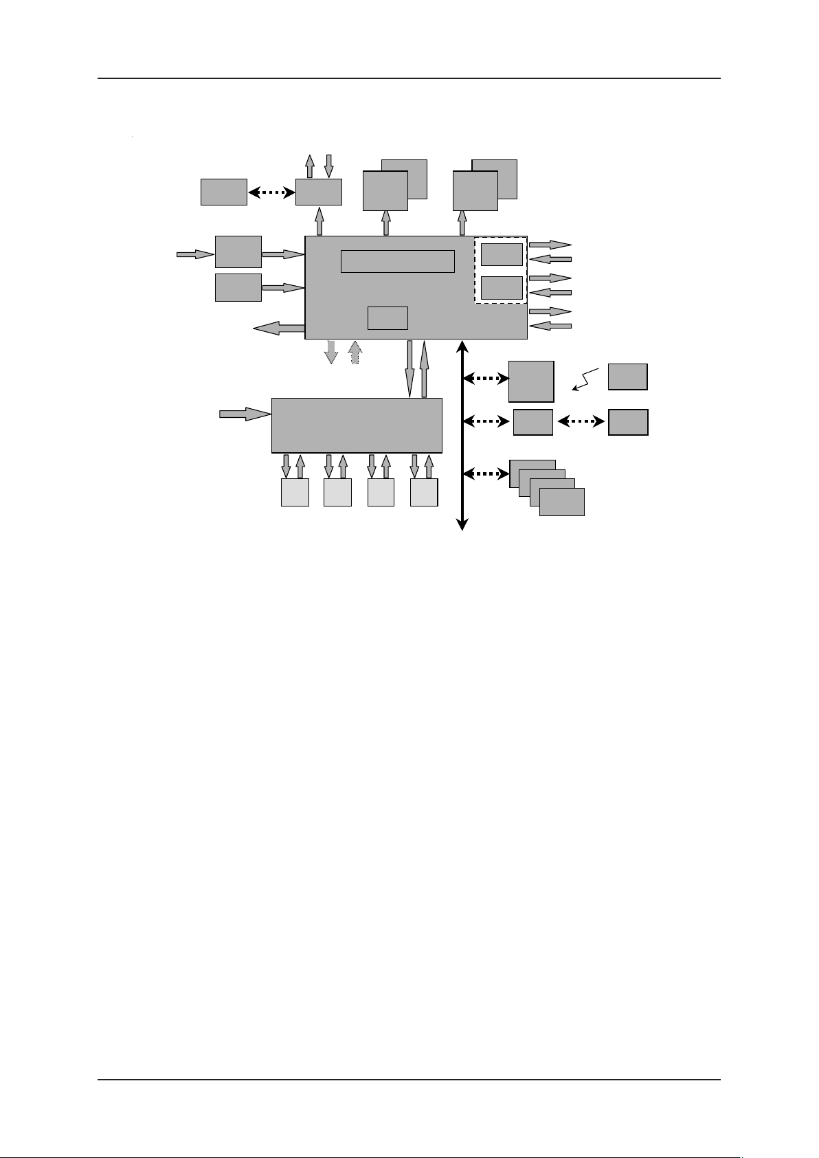
ARCHITECTURAL OVERVIEW
Mains
Dispenser light,
Electr totaliser
Dispenser I/O
Valves, motors and sensors
UAK
VRC
HVU
1
Battery
Low End H
(Single/Twin)
H1 H2 H3
H
(pulsers, valves, motors)
CSD-L
CSD-F
Calculator Module
2
Mainboard MB251
HCM
draulic
I/O Board
3
draulic Units
Displa
4
H4
s
CSD-L
CSD-F
Dipnet
COM
IEB
Interfaces
I/O extensions
Nozzle Bus
Interface
Communication
UAM/
5
UAK
OCB
tional Peripherals:
O
HOM
Hydraulic Option Modules
IRM
OPU
OPB
ODU
UPD
Product Indication
Others
Issue A
Fig. 1 Calculator Block Diagram
2.2.1 EXTERNAL POWER SUPPLY
The external power supply contains the following components:-
•A power distribution unit High Voltage Unit (HVU) including transformer
•A rechargeable back-up battery
2.2.2 MAINBOARD
The mainboard (version 3++) includes the calculator module and the Hydraulic
Controller Module (HCM):-
•The calculator module is able to manage two deliveries independently (one on
each road side); control the deliveries; maintain the volume and amount counters;
control the transaction displays and hydraulic units; and communicate with the
self-service device.
•The HCM is responsible for supporting the hydraulic interface by checking the
volume pulser devices; counting and checking the two incoming line volume
pulses; controlling the motor and valves and updating the electro-mechanical
totalisers.
The mainboard provides all the interfaces required to drive the ‘low-end’ hydraulics
without the need for an I/O board - single product and twin functionality (two
motors, two pulsers, four valves).
Document Ref 905675-001 Rev 2 Page 2-3
Page 20

Product Information WWC T1 Set Up & Maintenance Manual
Since the release of Version 3 of the mainboard, the NBB board has been
eliminated and the serial nozzle bus is directly controlled by the mainboard.
T wo optional modules can be directly connected to the mainboard (piggy-back):-
•The COM (Communications adapter) is used to interface the hardware to the
various self-service devices.
•The IEB (I/O Extension Board) is used to connect the peripherals often used in
Single/T win configurations e.g. preset keypad, simple set up and configuration
keypad.
2.2.3 I/O BOARD (VERSION 3++)
The I/O Board is a level converter and control signal distributor for one to four
single product hydraulic units.
2.2.4 TRANSACTION DISPLA YS
The transaction displays indicate the transactions on each side of the dispenser
showing the volume, amount and fuel price of the actual delivery. For each
side, it is possible to add a ‘slave’ display. Two different types of display are
available:-
•CSD-L : Liquid Crystal Display device
•CSD-F : Electromechanical Display device (Ferranti)
2.2.5 USER ACCESS DEVICES (UAK/UAM)
User Access Devices are used to set the basic set up and configuration for the
calculator and optional devices via an integrated keypad module for service
engineers (UAK) or via an infra-red remote control unit (UAM/IRM). It is
possible to get a readout of totals, errors and service parameters. Either the
UAK (also used for VRC configuration and calibration) or the UAM/IRM can
be used but both devices cannot be used in parallel.
2.3 Different Configurations
With the main components, the following configurations are possible:-
•Standard dispensers with up to four single products (refer to section 2.3.1)
•Low end dispensers: single product or twin configuration, super high speed single-sided
(Fleet) (refer to section 2.3.2)
In addition to the above configurations, the following options can be added via the Dipnet:-
•Vapour Recovery Controller Board (refer to section 2.3.3)
Issue A
•Option Controller Board (refer to section 2.3.4)
•Hydraulic Option Modules (refer to section 2.3.5)
•I/O Extension Board (refer to section 2.3.6)
Page 2-4 Document Ref 905675-001 Rev 2
Page 21
WWC T1 Set Up & Maintenance Manual Product Information
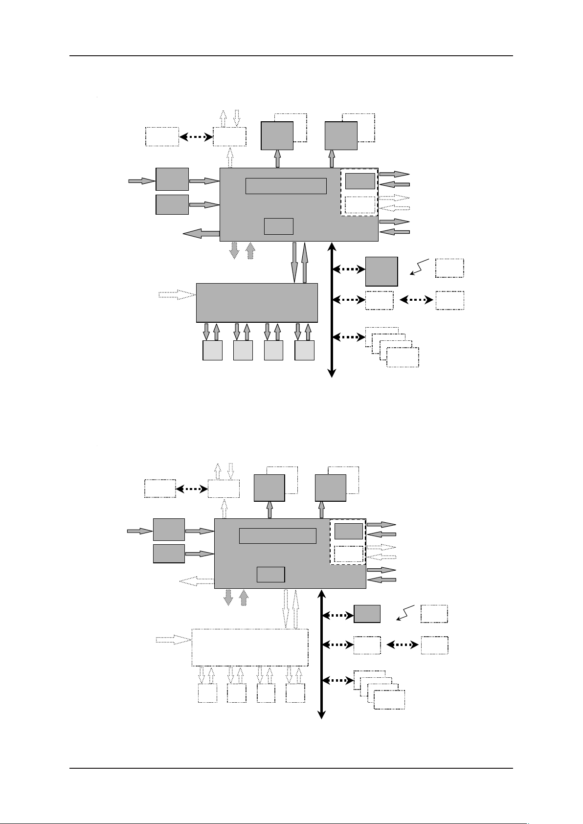
y
y
y
p
y
(
)
play
y
p
p
2.3.1 ST ANDARD DISPENSERS WITH UP TO FOUR SINGLE PRODUCTS
Mains
Dispenser light,
Electr totaliser
Dispenser I/O
Valves, motors and sensors
UAK
VRC
HVU
1
Battery
Low End H
(Single/Twin)
H1 H2 H3
H
(pulsers, valves, motors)
CSD-L
CSD-F
Calculator Module
2
Mainboard MB251
HCM
draulic
I/O Board
3
draulic Units
Displa
4
H4
s
CSD-L
CSD-F
Dipnet
Communication
COM
IEB
Interfaces
I/O extensions
Nozzle Bus
Interface
UAM/
5
UAK
OCB
tional Peripherals:
O
HOM
Hydraulic Option Modules
IRM
OPU
OPB
ODU
UPD
Product Indication
Others
Issue A
2.3.2 LOW-END DISPENSERS : SINGLE PRODUCT OR TWIN
Mains
Dispenser light,
Electr totaliser
Dispenser I/O
Fig. 2 Standard Dispenser Block Diagram
CONFIGURA TION, SUPER HIGH SPEED, SINGLE-SIDED (FLEET)
Valves, motors and sensors
UAM
HVU
Battery
VRC
1
Low End H
Single/Twin
H1 H2 H3
H
draulic Units
(pulsers, valves, motors)
CSD-L
CSD-F
Calculator Module
2
Mainboard MB251
HCM
draulic
I/O Board
3
H4
Dis
4
s
CSD-L
CSD-F
Di
COM
IEB
net
UAM
OCB
O
Hydraulic Option Modules
Communication
Interfaces
I/O extensions
Nozzle Bus
Interface
5
tional Peripherals:
HOM
IRM
OPB
UPD
Product Indication
Others
OPU
ODU
Fig. 3 Low End Dispensers Block Diagram
Document Ref 905675-001 Rev 2 Page 2-5
Page 22

Product Information WWC T1 Set Up & Maintenance Manual
2.3.3 VAPOUR RECOVERY CONTROLLER BOARD (VRC)
The VRC is an independent module which communicates with the calculator
module. After the VRC is initialised at each delivery start, it performs the open
or closed loop vapour recovery process by controlling its own motors and valves.
2.3.4 OPTION CONTROLLER BOARD (OCB)
The Option Module provides an interface to optional modules such as:-
•Unit Price Displays (UPD)
•Product Indicators
•Traffic Lights
•OPU/ODU (as replacement of the above)
•Preset Keypads
2.3.5 HYDRAULIC OPTION MODULES (HOM)
Up to four Hydraulic Option Modules can be connected to the mainboard via the
Dipnet to operate in a similar way to the HCM. The HOMs are designed to
provide the interface to optional hydraulic units eg. Super High Speed, Satellite,
Blender or to extend the number of products to a maximum of five.
Like the HCM, the HOM is responsible for supporting the optional hydraulic
interface by checking the volume pulser devices, counting and checking the two
incoming line volume pulses and by controlling the motor(s) and valves.
2.3.6 I/O EXTENSION BOARD (IEB)
The I/O Extension Board is designed to connect peripherals often used in lowend configurations (single/twin). The IEB is a piggy-back board attached to the
mainboard and is easy to assemble. The IEB is able to interface to:-
•A preset keypad (same functionality as connected to OCB)
•A simple configuration keypad (dispenser configuration only, no VRC). This
keypad is kept inside the calculator head.
•Four spare additional outputs
2.4 Product Option Matrix (POM)
The product option matrix defines the options of WWC available for each application. For
release status, please check the Software Status Overview. Refer to Appendix A for the
POM.
Note: Not all country specific W&M options are listed (e.g. low-level detection Italy,
display reset methodology for UK etc.)
Issue A
2.5 Functionality
Refer to the POM in Appendix A for supported functions per application.
Page 2-6 Document Ref 905675-001 Rev 2
Page 23

WWC T1 Set Up & Maintenance Manual Product Information
2.5.1 FUNCTIONALITIES PER HOSE
40 (45) litres per minute - Petrol or Diesel
Standard speed flow rate is achieved using one pump and one meter.
40 (45) litres per minute for two filling positions - Petrol or Diesel
Standard speed flow rate is achieved using one pump and two meters.
80 (90) litres per minute - Diesel only
High speed flow rate is achieved using one pump and one meter.
Note : 90 litres per minute for UK only.
130 litres per minute - Diesel only
V ery high speed flow rate is achieved using one pump and two meters in parallel.
150 litres per minute - Diesel only
Super high speed flow rate is achieved with two pumps and two meters in parallel.
40/80 litres per minute (Push Button selection) with one nozzle - Diesel
only
The standard flow rate is 40 litres per minute. A push button is available to
enable the selection of a higher flow rate of 80 litres per minute for trucks. A
double valve system in the hydraulic unit is required.
40/130 litres per minute or 40/80 litres per minute with two nozzles Diesel only
The first nozzle dispenses the standard flow rate of 40 litres per minute. If the
second nozzle is used then the higher flow rate for trucks is given. A special
valve system in the hydraulic unit is required.
Satellite Connection
This function enables the connection of a slave or satellite dispenser to a master
dispenser. The satellite dispenser has a maximum configuration of a display,
calculator lighting, satellite button and nozzle switch.
Submerged Standard
A timer can be activated via the Maintenance menu to enable this function. The
submerged pump starts running when the nozzle is lifted then, after approximately
three seconds, the valve in the dispenser is opened.
Issue A
Submerged Mouvex
Similar functionality to Submerged Standard with an additional switch for the
Mouvex air separator which is managed by the calculator.
Blender
Blending mixes two fuel grades in a certain ratio to give a third grade blend with
another octane. This is preferable under some fuel taxation systems, for example,
in Scandinavia.
Document Ref 905675-001 Rev 2 Page 2-7
Page 24

Product Information WWC T1 Set Up & Maintenance Manual
The choice is made by push button selection with product indication.
There are two principles:-
• 2 grades in, 3 grades out, 2 hoses
•2 grades in, 3 grades out, 1 hose
Refer to section 6.18 for programming information.
Combined Hose
The Combined Hose option allows two or more products to be delivered through
one common hose. Each product has its own hydraulic block (pump/meter)
which controls the valves and routes the fuel to the associated combined hose.
The choice is made by push button selection with product indication. In special
cases, for example Tatsuno application, the last product used is pre-selected by
default when the nozzle is next lifted.
Refer to section 6.14 for programming information.
Electronic Controlled Vapour Recovery (VRC)
T o support VRC, volume information is routed to a VRC main controller which
controls the motor and valves of the VRC system. The VRC system is available
as an open loop or self-calibrated loop system.
Vapour Leak Detection
A specific leak detection method is required for France in conjunction with vapour
recovery. After the nozzle is replaced, the calculator keeps the pump motor
running to check for leakages. The length of time for the pump motor to run and
the amount of volume to be detected for a leak is fixed and cannot be changed.
If detected, the leak error is forwarded to the system. If the same error is found
three times then the applicable product will be blocked. The calculator keeps
track of the leak status per product.
Parameter:
-hose expansion volume : 5 cl for 40 l/min
10 cl for 80 l/min
40 cl for 130 l/min
-hose expansion time : 1 second
-leak volume : 2 cl
-leak time : 2 seconds
Refer to section 6.10.1 for programming information.
Esso Leak Detection
This function is designed for use at unmanned service stations with IFSF
application. After the nozzle is replaced, the calculator keeps the pump motor
running to check for leakages. The length of time for the pump motor to run and
the amount of volume to be detected for a leak is entered via this menu.
Page 2-8 Document Ref 905675-001 Rev 2
Issue A
Page 25

WWC T1 Set Up & Maintenance Manual Product Information
If detected, the leak error is forwarded to the system and will immediately block
the complete dispenser. The calculator keeps track of the leak status.
Parameter:
-hose expansion volume : 5 cl for 40 l/min
10 cl for 80 l/min
40 cl for 130 l/min
-hose expansion time : 1 second
-leak volume : 2 to 8 cl
-leak time : 2 seconds
Refer to section 6.10.3 for programming information.
Fuel Leak Detection
At the start of each delivery, a leak test is started via a request from the kiosk.
Up to three attempts are made to verify the leak. If the leak is verified, the
results of the leak tests are forwarded to the kiosk via special messages.
Parameter:
- volume (v) : 0 to 45 cl default = 0
-time (t) : 0 to 20 second(s) default = 0
Refer to section 6.17 for programming information.
Axial Flow Meter (AFM) Leak Detection (kernel >= 3.02)
This function can identify a potential AFM spindle lock situation which could
result in a leakage of approximately 1.2 to 1.5 gallons per minute.
The assumption is made that “an AFM leak situation occurs when the ‘no flow’
timeout occurs n times in a sequence AND the total reported volume is 0”.
Normally , during a delivery , the “no flow” timer is restarted each time a volume
update is done. When the timer expires i.e. no flow during the “no flow” period
(default = 1 minute within a range of 0 to 9:59 minutes), the delivery will be
stopped and the motor and valves switched off without indicating an error .
To be able to detect an AFM spindle lock situation when the “no flow” timer
has expired, the corresponding volume is checked:-
•If volume > 0 : no change in the behaviour, reset the leak sequence counter of
the associated hose (product/side)
Issue A
•If volume = 0 : increment the leak sequence counter of the associated hose
(product/side)
If the counter exceeds the predefined (not user adjustable) limit of three (3)
then an error will be logged and reported. The associated hose will be blocked
until a manual release action is performed. Lifting the nozzle of a blocked hose
will display the error again but it will not log another error.
Document Ref 905675-001 Rev 2 Page 2-9
Page 26

Product Information WWC T1 Set Up & Maintenance Manual
If the nozzle is replaced with volume = 0 before the time out expires, the leak
sequence counter is neither incremented nor reset i.e. this will not increase the
volume lost if it is a real leak.
If an error is detected, all motors and valves will be switched off and the error
will be logged and displayed with the standard error format:-
Error
HC p s
65
p : product
s : side (R/L)
Note : If HOMs are used, HC may be displayed as H1 to H4.
Error Reset Menu
Within the Maintenance menu, the sub-menu AFM-Leak (FLPROT - Flow
Protection menu) needs to be added to display the status of each installed product
per side. For standard dispensers this is related to the hose and for SHS/Satellite
dispensers, it is related to the product.
ON : Hose is activated and ready for use
OFF : Hose is blocked due to leak error (or manually set to OFF)
Note : It is not possible to cover all leak situations and a certain amount of
volume may still be lost.
Fraud Detection
This function is designed to prevent uncontrolled fuel flow by the detection and
control of such situations as far as possible using a limited scope of detection
methods and actions.
Additional sensors on the Nozzle Bus enable the meters/pulsers to detect any
rotations and the calculator will switch off all transactions (where possible) and
log the unexpected flow events. This functionality requires the use of specific
hardware i.e. sensors using the Hall Sensor Controller (HSC).
This function is not available in all installations due to the maximum limit of 32
sensors on the sensor bus. Only existing piston meters will be supported; AFM
will not be supported.
2.5.2 FUNCTIONALITIES PER SIDE
REMOTE PRESET VALVES
Preset valves are controlled remotely by the Pump Controller.
LOCAL PRESET VALVES
There are two methods available to control the Local Preset valves depending
on the hardware used:-
•Push buttons
•Keypad
Issue A
Page 2-10 Document Ref 905675-001 Rev 2
Page 27

WWC T1 Set Up & Maintenance Manual Product Information
Push Button Methods
- Push buttons connected to the sensor bus or direct connections
- Push buttons connected to the IEB
Up to four buttons (three amount or volume and one reset button) are available
and can be connected to the sensor bus, direct connections or via IEB at each
filling position. In combination with preset valves, it is possible to fill up with the
fixed preset amount or volume.
preset code button 1 button 2 button 3 button 4 Ty pe
clear Value_1 Value_2 Value_3
1 Y 100 500 1000 Amount
2 Y 500 1000 5000 Amount
3 Y 1000 5000 10000 Amount
4 Y 200 500 1000 Amount
5Y 1510VOLUME
6 Y 11050VOLUME
7 Y 1000 2000 5000 Amount
8 Y 5000 10000 50000 Amount
9 Y 2000 5000 10000 Amount
10 Y 5000 10000 20000 Amount
11 Y 10 50 100 Amount
12 Y 500 1000 1500 Amount
13 Y 100 500 2000 Amount
Issue A
The parameters used for local preset push buttons are as follows:-
- Y = function supported N = function not supported
- Value_1, Value_2 and Value_3
Each time a button is pressed, the amount or volume is increased by the
corresponding value. The volume is always defined in litres. The amount needs
to be updated using the comma position as defined by the specified country (for
further information, refer to Appendix B).
Example 1
If Value_1 = 500 and Spain is selected (Country code 0034), each push of the
button increases the amount by 500 Ptas because the “comma position” of the
amount display is 0 (refer to Appendix B).
→ (0034 SPAIN 0 / 2 / 1)
Example 2
If Value_1 = 500 and The Netherlands is selected (Country code 0031), each
push of the button increases the amount by 5,00 Dfl. since the “comma position”
of the amount display is 2 (refer to Appendix A).
→ ( 0031 NETHERLANDS 2 / 2 / 3)
Note: To select the push button functionality via the IEB, the jumper W300
on the IEB must be closed (refer to Appendix D for Jumper Positions).
Document Ref 905675-001 Rev 2 Page 2-11
Page 28

Product Information WWC T1 Set Up & Maintenance Manual
Keypad Methods
- Keypad connected to the IEB
- Keypad connected to the OCB
123
456
789
CASH
When Local Preset is connected using a keypad method, a 4x4 keypad is available
at each filling position to allow the entry of a preset amount or preset volume.
With the keypad layout as shown, volumes and/or amounts can be entered in
decimals.
Note: Please check the appropriate Product Releases Notes for the
supported functionality of the “Credit” and “Cash” button.
Car Detection
0
,
preset
clear
CREDIT
preset
amount
preset
volume
A special device (i.e. inductive coil) detects if there is a car present at the filling
position and transmits this information via a potential free contact to the calculator.
This will enable the calculator and inform the site controller when the car is
leaving.
Continuous Filling Button for Satellite
Depending on the application, this button must be pressed before or within three
seconds of the replacement of the nozzle of the master or satellite dispenser.
This keeps the pump in ‘released’ mode for the “maximum time a filling can be
suspended” period. T o continue the filling at the satellite dispenser , the valves in
the pipework are switched via the nozzle contact. The calculator then continues
the transaction started at the master dispenser. The push button is located adjacent
to the nozzle boot on the dispenser. Refer to Satellite Nozzle Control Menu
per dispenser side for further information.
Product Indication on the Display at start of the filling
When the nozzle is lifted, the associated product light is illuminated briefly (M3000
application only).
Idle Display Control Menu
This menu determines which information is displayed when the dispenser is idle.
The following selections can be made:-
Issue A
Page 2-12 Document Ref 905675-001 Rev 2
Page 29

WWC T1 Set Up & Maintenance Manual Product Information
0 displays last delivery
1 filling is cashed and the volume and amount display show “0”
2 filling is cashed and all displays show “0”
3 to 9 reserved for future implementations
Satellite Nozzle Control Menu
A high speed diesel dispenser can have a satellite nozzle on each side. At each
nozzle, a filling can be started and the following selections can be made:-
0 satellite function disabled
3 at the master or satellite nozzle
4 at the master or satellite nozzle - once the filling is continued at
the satellite nozzle, it is not possible to continue again using the
master nozzle.
This selection is required by W&M in France to prevent fraud.
5 to 9 reserved for future implementations
Release Management Menu
T o release a dispenser for the next filling, the following selections can be made:-
0 release only via the forecourt controller system - no manual release
possible
1 release can be via the forecourt controller system and IR remote
control:-
• push button 9 to release right/side A
• push button 7 to release left/side B
2 release via the forecourt controller system and button on the
dispenser
3 to 9 reserved for future implementations
Maximum Time for a Filling Menu
This is the maximum time the pump motor can be active. It starts when the
nozzle is lifted from the nozzle boot.
Parameters:-
•function is disabled 0000
•max. time 5959 (= 59 minutes and 59 seconds)
•default value 1500 (certain applications may overrule this e.g.
Dunclare default value = 1000)
Issue A
Maximum Time for a Filling to be Suspended Menu
Within the set time period, a filling has to be started (released via payment
terminal) or continued at a satellite dispenser. When this time has elapsed, the
filling is assumed to be finished and the dispenser will have to be released again
before a new filling can be started.
Document Ref 905675-001 Rev 2 Page 2-13
Page 30

Product Information WWC T1 Set Up & Maintenance Manual
Parameters:-
•function is disabled 0000
•max. time 0959 (= 9 minutes and 59 seconds)
•default value 0100 (certain applications may overrule this)
Time Between Two Fillings Menu (Inter delivery time out)
This is the minimum time to elapse between two successive fillings.
Parameters:-
•function is disabled 0000
•max. time 0959 (= 9 minutes and 59 seconds)
•default value disabled 0000 (certain applications may overrule this
e.g. Dunclare : fixed at 5 seconds)
Maximum Time of No Flow Menu
This is the maximum period allowed between powering the pump motor and the
detection of fuel flow. If no flow is detected, the pump motor switches off.
Parameters:-
•deliveries are disabled 0000
•max. time 0959 (= 9 minutes and 59 seconds)
•default value 0100 (certain applications may overrule this)
Delivery Mode
The calculator must totalise the amount, volume and number of fillings according
to the delivery mode selected. The delivery mode is set as follows:-
•Standalone 0
•Console cash 1
Product Position
This defines the position of the Electromechanical Totalisers (EMT), the Unit
Price Displays (UPD) and the Product Lights per product and per side. It is not
possible to select another UPD position for product 1 other than the appropriate
EMT.
For programming information, refer to section 6.xx
•Product 1 to 5 - position 1
- position 2
- position 3
- position 4
- position 5
Issue A
Note: This menu has been removed from the Option Controller Board (OCB)
menu because the EMTs are not controlled via the OCB. The UPD and
Product Lights are controlled via the OCB.
Page 2-14 Document Ref 905675-001 Rev 2
Page 31

WWC T1 Set Up & Maintenance Manual Product Information
Note: The request to program EMT positions for left-hand dispensers
(PMR297) means that the EMT connector must always be used for 4/5
products on the Optional Peripheral Board (OPB).
OCB Functionality
When an OCB board is connected, the following functions can be selected:-
•Lights (Traf fic Lights, Indication Lights)
Two coloured lights (red and green) indicate the state of the dispenser.
off disabled (default)
1 application dependent
(please check the appropriate documentation for support)
2 default kernel function
IDLE - Green is on
FILLING - Red is on
•Product Lights (Product Indication)
Between two and five lamps light a coloured glass through the front plate of the
calculator housing. Each light corresponds to one of the product stickers located
on the front plate. During a filling, the appropriate light will be on or flashing and
the other lights will be switched off.
off disabled (default)
1 application dependent
(please check the appropriate documentation for support)
2 default kernel function
IDLE - all lights on
FILLING - only the light for the selected product is on
•Unit Price Displays (UPD)
Additional Unit Price Displays show unit prices for all available products:-
off disabled (default)
1 application dependent
please check the appropriate documentation for support)
2 default kernel functionality
IDLE - all unit prices shown
FILLING - only the unit price of the selected product shown
•LCD Display
Additional user displays are not yet supported
off disabled (default)
Issue A
•V olume and Amount Pulses
To support outdated interfaces for Outdoor Payment Terminals (OPT), the
calculator provides two channel pulse outputs each for the actual delivered volume
and amount.
Document Ref 905675-001 Rev 2 Page 2-15
Page 32

Product Information WWC T1 Set Up & Maintenance Manual
- volume unit (number of cl/pulse) 1 to 10 (default = 1)
- volume period (value * 0.25 ms) 5 to 40 (default = 5)
- amount unit (number of units/pulse currency unit)
1 to 10 (default = 1)
- amount period (value * 0.1 ms) 10 to 99 (default = 10)
•Fleet Functionality
In addition to the volume and amount pulses, the “Fleet Functionality” is added
for outdated interfaces to certain controllers.
An OCB output (OUT_SPARE) is reserved to indicate a request for release
and an input (OPT_INPUT) is reserved for the “controller” to release the
dispenser. This requires a special release sequence:-
- calculator will set OUT_SPARE if a nozzle is lifted
- the filling can only start if the controller sets the OPT_INPUT
- the controller can interrupt or stop the filling when resetting the
OPT_INPUT
This release functionality is activated via the RELEAS submenu in the OCB
menu.
For the applicable input and output refer to the OCB definitions in the Appendix.
2.5.3 FUNCTIONALITIES PER DISPENSER
Common Set-Up Codes
The common set-up codes have been defined for the new dispenser range in the
following table.
Refer to the hydraulic flow diagrams for a symbolic drawing regarding supported
hydraulic configurations.
Note : there is also a fleet version of WWC available (volume only display).
Kernel
Version
all 50 Double
01.07 51 Double 4
02.00 51 Single
>
>
01.09 52 Double
01.09 53 Double
>
03.11 53 Double 1 mot or 1 130 l/min/ SAT 900238
>
01.09
>
>
01.09 55 Double
Hydr
Set up No
Sided
Additional
Description
No of
Products
Flow Rates/Product s Drawing No
5 40/80 l/min button per s i de
130 l/m i n SAT and 3x40 l/min per
side
130l/m i n SAT (SHS on M ai nboard)
1
SHS with 1 product on bot h sides ; 9235110580
4
130 l/m i n/SA T and 3x40 l / m i n per
side
80 l/m i n SAT and 3x40 l/min per
4
side
160 l/m i n/SA T154 Double
1
130 l/m i n/SA T and 1x40 l / m i n
9235110557
900236
9235110???
9235110619
900246
900237
9235110581
900238
9235110582
900239
9235110583
900240
Issue B
Page 2-16 Document Ref 905675-001 Rev 2
Page 33

WWC T1 Set Up & Maintenance Manual Product Information
Kernel
Version
>
01.09
Hydr
Setup No
56 Asymmetric
Sided
Additional
Description
No of
Products
5 right
Flow Rat es/Products Drawing No
130 l/min/SA T and 4x40 l/min
(right);
9235110584
4 left 4 x 40 l/mi n (left) 900241
01.09
>
01.09 58
>
>
01.10 60 Double LPG
>
02.15 61 LPG low-end Extended func tionalit y 901335
57 Asymmetric
Double
Twin
4 right 4 x 40 l/min (right); 9235110585
5 left 130 l/ m in/S AT and 4x40 l/min (l eft) 900242
Product 1 and 3 x 40 l/min (ri ght); 9235110586
4
Product 2 and 3 x 40l/min (l eft) 900243
LPG and 4 x 40 l/ m in per side 9235110618
5
900245
SHS wi th different product s on
>
03.12 62 Double 4
both sides
906015
130 l/min/SA T and 3 x 40 l/min
03.16 63 Double
>
Different
products on
both sides
80 l/min/SA T and 3x40 l/min per
4
side
906377
Different
> 03.16 64 Double
products on
1 160 l/min/SA T 906378
both sides
Different
03.16 65 Double
>
products on
1 130 l/min/SA T and 1 x 40 l/min 906379
both sides
01.09 70 Double Blender
>
3 products in, 5 products out (2
hoses/side);
9235110591
2 blend products 1in + 2in / 1in +
3in
>
01.09 71 Doubl e Blender 3 products in, 4 products out ; 9235110612
1 blend product 1 i n + 2 in
>
01.09 72 Doubl e Blender 3 products in, 4 products out ; 9235110610
1 blend product 1 i n + 2 in
01.09 73 Doubl e Blender 4 products in, 5 products out ; 9235110614
>
1 blend product 1 i n + 2 in
Issue B
01.09 74 Doubl e Fak e Blender 3 products i n, 4 products out 9235110611
>
>
01.09 75 Doubl e Blender 3 products in, 4 products out ; 9235110609
1 blend product 1 i n + 2 in
3 products in / 3 products out on
>
01.09 76 Double Blender
one hose, and 40l/min per side
9235110613
(in=out)
02.00 77 Double Blender ????????? 9235110???
>
900244
03.19 80 Double
>
Oil M ix 3 Oil M ix + 2 x 40l /mi n per side
906927
906928
03.07 90 Doubl e Comb Hose 4
>
Document Ref 905675-001 Rev 2 Page 2-17
2 com bined hose products on firs t
hose
905148
Page 34

Product Information WWC T1 Set Up & Maintenance Manual
Backlight for LCD
The backlight is standard with LCD displays.
Switch Dispenser Lighting
If defined in the application, the switch for the dispenser or calculator lighting is
via a command from the forecourt controller system.
Electronic Totaliser
The totals of amount, volume and number of fillings per nozzle are stored in the
calculator for single, blended and high speed configurations. T otals and subtotals
are also available per delivery mode (two modes). This information is permanent
and cannot be erased or changed unless a “cold start” or “service start” is
performed which would erase all the data in order to prevent data corruption.
Voice Synthesizer
The calculator controls the voice synthesizer in order to output the required
sentence (only the French language is supported). This principle will enable
other languages to be stored.
Remote Reset - Thermal Overload (Pump Motors)
When the thermal protection of the motor is tripped during three sequential fillings,
the motor cannot be switched on again by the calculator without user intervention.
Reset can be done via the service keypad, hardwired input (General Purpose
Input, depending on the selected application) or by switching the power on/off.
When the thermal protection trips before the third sequential time, the motor is
automatically started after the two corresponding nozzles have been replaced
and lifted again.
Note : Applications using kernel version 01.xx will block the motor each
time the thermal protection is tripped.
Note : When testing the Thermal Protection, it may be necessary to increase
the “Maximum time of no flow” to prevent the motor from being switched
off by the calculator.
Refer to section 6.9 for programming information.
Uploading Totals
This function enables the upload of the totals from the calculator to the system.
When the calculator is configured to be used in system mode but is switched
temporarily to standalone mode, the standalone totals are downloaded to the
Point of Sale (POS).
Issue A
Country Code Menu
The country code is predefined and can only be set during a cold start. Refer to
Appendix B for the table of implemented country codes and related variables.
Refer to section 6.7 for programming information.
Page 2-18 Document Ref 905675-001 Rev 2
Page 35

WWC T1 Set Up & Maintenance Manual Product Information
Node Address Menu
This function is required for multi drop communication links (e.g. IFSF) to select
the address of the calculator on the network.
Refer to section 6.20 for programming information.
Test Delivery Menu
This module monitors volume and flow in the following ways:-
•total flow and total volume
•volume of each meter
•flow of each meter
Refer to section 6.21 for programming information.
Product Name
This function displays a name for a product when setting or changing unit prices
or reading totals. This can be done character by character or from a pick list.
Refer to section 6.23 for programming information.
Key Lock to protect access to Calculator Data (Programming Switch)
It is a legal requirement in some countries (e.g. UK) to protect the calculator
configuration and database information by a key lock.
A key lock or switch can detect the opening of the calculator housing and prevent
access to the database or allow read-only access.
Note: PIN codes are not permitted.
Software versions
It is possible to see the versions of all connected peripherals in following order
(depending on kernel version):-
Kernel version 01.xx
Applic Application
GCI Kernel
OCB Option Controller Board
HCM Hydraulic Control Module
SOM Sound Option Module
ECVR VRC Module
UAM User Access Module
HOM Hydraulic Option Module
Issue A
Document Ref 905675-001 Rev 2 Page 2-19
Page 36

Product Information WWC T1 Set Up & Maintenance Manual
Kernel version >= 02.xx
OC Option Controller Board
HC Hydraulic Controller Module
CS1R CSD 1 Right
CS2R CSD 2 Right
CS1L CSD 1 Left
CS2L CSD 2 Left
SO Sound Option Module
EC VRC Module
UA User Access Module
H1 Hydraulic Option Module 1
H2 Hydraulic Option Module 2
H3 Hydraulic Option Module 3
H4 Hydraulic Option Module 4
D1 Diagnostic
GCI Kernel
Applic Application
CHS Checksum of main controller Eeprom
(containing the kernel and the application)
Disable Station Manager PIN
This function will enable access via an additional input if the Station Manager
PIN is not known. It is application dependent and therefore only active when
the calculator head is open.
LPG
When one of the LPG set ups (set up 60 or 61) is selected, the following functions
will be supported:-
•The LPG Delay Menu defines the use of nozzle switches or Deadmans buttons
value = 0 Nozzle Switch used
Ignore Deadmans Button when the nozzle is replaced
value = 1 to 29 Deadmans Button only
Delivery will be started when the button is pressed.
The end of a delivery is determined by the value
(delay in seconds) after the button is released
•The LPG nozzle menu defines if the nozzle function is supported (yes or no).
•The LPG Pulse menu allows the meter selection (during set up only)
1 Tatsuno meter : 0.5L/rev (one pulse equals 1 cl.)
2 Schwelm meter : 1L/rev (one pulse equals 2 cl.)
For more information on LPG options, refer to section 3.
EMPD
This function enables the WWC to operate a dispenser without mains power
being present. The pump is operated by a cranking device and the calculator is
operated using battery power.
Note : Special hardware is needed to support this function.
Page 2-20 Document Ref 905675-001 Rev 2
Issue A
Page 37

WWC T1 Set Up & Maintenance Manual Product Information
Nozzle Input Type
This function allows the selection between two different types of nozzle input:-
•V alue “no” - normal nozzle switch position i.e. always OPEN in idle and CLOSED
when nozzle lifted - for all dispensers except Q500T1.
•Value “In” - inverted nozzle switch i.e. always CLOSED in idle and OPEN
when nozzle lifted - for Q500T1 dispenser only .
Note : Only available with kernel version >=3.18
Master PIN Code
The basic functionality of the Master PIN Code is to prevent access to the
WWC’s menus while still allowing read only access to the totals.
Note : Only available with kernel version >=3.16
2.5.4 WEIGHTS & MEASURES RELA TED FUNCTIONALITY
Maximum Pulse Sequence Error
The pulse handling module allows for a number of pulse sequence errors. The
error normally indicates a pulser problem, for example, inconsistency in the pulse
count of both pulser channels.
The value of this parameter is not configurable via any menu. It is defined
within the country code or application.
Rounding Type
This function is used to handle country specific rounding rules for the amount
values. The defined parameter specifies the rounding of the last two digits of
the amount delivered as displayed on the amount display . Rounding types 1 and
2 refer to the last digit only .
The rounding type is defined within the country code with the values as follows:-
Type Method Description
1 1 by 1 Dis play all the values of the last digit (no rounding)
25 by 5
3 10 by 10
The calculat or rounds t he las t digit t o t he nearest value
or 0 or 5
The calculat or rounds t he s ec ond las t digit one up when
the last digit is 5 or higher. The last digit will be set to
zero.
Issue B
Refer to Appendix B for more information.
Low No Filling Time
This option refers to a ‘hydraulic time out’ function used to detect the end of the
flow . After switching off the motor/valves, the flow does not end immediately
because of the system characteristics. If no pulses are detected during this
‘low no filling time’ then an “end of the flow” message is generated. If pulses
are detected then the time out is restarted. The value of the ‘low no filling time’
is typically 0.5 seconds and cannot be altered.
Document Ref 905675-001 Rev 2 Page 2-21
Page 38

Product Information WWC T1 Set Up & Maintenance Manual
Pulser Test Time
Before starting a delivery, the pulser is tested during a specified ‘pulser test
time’. During this test, the valves remain closed and the pulser is checked on
consistent high/low values of both channels and there should be no pulses
generated during this period. The value of the ‘pulser test time’ is typically 1
second and cannot be altered.
Hose Expansion
This feature is designed to prevent “non zero display” problems caused by
evaporation of fuel in the pipes/hose between the volume meter and the nozzle.
The pulser may generate pulses when the nozzle is lifted but not triggered and
the pump motor has started to run before any fuel is dispensed. This will
pressurise the hose and can cause the hose to expand.
This function allows the limited amount of pulses detected by the pulser in the
above situation to be deleted. It can also be used for leak detection and is a legal
requirement in certain countries e.g. Italy .
The Hose Expansion feature is only activated when the nozzle has been unused
for more than one hour.
The number of hose expansion pulses and the duration period are defined within
the country code and cannot be altered except for France - refer to Appendix B
for more information.
Pulser Hide
This function works together with the Hose Expansion function by preventing
the display from showing the centilitres measured during the initial pressurisation
of the hydraulic system. It still counts the pulses but hides the display from the
customer to avoid confusion. When the number of pulses exceeds the set limit,
the display shows the delivered volume. The Pulser Hide feature is active at the
start of every filling.
The number of pulse hide pulses is defined within the country code and cannot
be altered.
Euro
When activated, this function will overrule the display layout previously selected
by the country code.
The resulting display layout will be:-
XXXXXX
XXXXXX
XXXX
€
L
€ / L
Issue B
Rounding method will be set to T ype 1 (1 by 1).
The Euro functionality can only be selected with European country codes when
running a cold start or
via the Maintenance menu. Once activated, it can only
be reset by performing a cold start.
Page 2-22 Document Ref 905675-001 Rev 2
Page 39

WWC T1 Set Up & Maintenance Manual Product Information
Note : For European Community countries, selection of the Euro is only
possible up to kernel version 03.12. In later kernel versions, the Euro
selection is fixed.
Heavy Lei
This function is designed to enable the conversion to Heavy Lei currency in
Romania by simple (software) switch. Once Heavy Lei is selected, it cannot be
changed back without a Cold Start.
Note : This menu is only available with country code 40 (Romania).
Gallon
Gallons are selected and handled in two different ways:-
•Gallon meter /Pulser input
This function is automatically selected when the country code 001 (USA) is
chosen. Only gallon inputs are allowed (1000 pulses/gallon) and the Gallon
menu disappears.
Note : The Euro and Gallon functions must be used exclusively. Both options
impact upon Weights & Measures Regulations because they directly
influence the volume and/or amount display(s).
•Litre meter /Pulser input
Issue B
When the selected country code is not 001, the Gallon menu can be selected.
When activated, the standard litre input (100 pulses/litre) will be recalculated
and displayed in gallons.
Gallon Type
When the Gallon option is set to “yes”, then a specific gallon type can be selected
from the following values:-
•“US” - 1 US Gallon = 3,7854 litres
•“InnP” - 1 Imperial Gallon = 4,54609 litres
Note : When in Gallon mode, the.volume display, electronic totals, EMT
and Preset inputs will all be displayed in gallons.
Scaling
The Scaling function allows the unit price display to be represented by a different
unit than the amount display . For example, in Germany , the amount is displayed
in Euros with two digits after the comma and the unit price is displayed in
Eurocents with one digit after the comma (NOT is Euros with three digits after
the comma).
Using the Scaling menu, it is possible to shift the comma position for the unit
price. The value entered must be the number of digits to shift the comma to the
right. In the German example above, Scaling would be set to 2.
Document Ref 905675-001 Rev 2 Page 2-23
Page 40

Product Information WWC T1 Set Up & Maintenance Manual
EMT
T wo EMT options are available for selection following a cold start:-
•V alue “d” = double-sided EMT (each nozzle of a product has an individual EMT
total)
•V alue “s” = single-sided EMT (the left and right totals of the same product are
added and output to the right EMT)
Cent Overshoot Hide
This function is designed around the cent overshoot problem. When the amount
on the display is a rounded value and the No Flow Timer has elapsed, the software
will mask an adjustable number of pulses, called P
Note : This menu is only available with country code 33 (France).
Q500T1 Four Position Product Indicator (OCB)
This function is designed for the Q500T1 dispensers fitted with a small front
plate and 4 position product indicator. When set, the EMT/Product Indicator
Lights on the left side are shifted one position to the right:-
mask
.
12345
1234
Issue B
Page 2-24 Document Ref 905675-001 Rev 2
Page 41

WWC T1 Set Up & Maintenance Manual LPG Set Up
CONTENTS
3 LPG SET UP.................................................................................................................. 3-2
3.1 LPG Functionality.................................................................................................3-2
3.1.1 LPG Pulse Menu .................................................................................3-2
3.1.2 LPG Nozzle Flag Menu .......................................................................3- 2
3.1.3 LPG Delay T imer Menu ......................................................................3-3
3.1.4 LPG Motor Off Timer Menu...............................................................3-3
3.2 LPG Hydraulic Functions .....................................................................................3-4
3.2.1 Valves ..................................................................................................3-4
3.2.2 Hydraulic Schematic............................................................................3-5
3.3 Functionality with Nozzle Switch .........................................................................3-6
3.3.1 Timing with Nozzle Switch & Motor Off Delay
3.3.2 Timing with Nozzle Switch & Motor Off Delay = 0 ...........................3-6
3.4 Functionality without Nozzle Switch ....................................................................3-7
3.4.1 Timing with Deadmans Button only & Motor Off Delay
3.4.2 T iming with Deadmans Button only & Motor Of f Delay = 0..............3-7
≠≠
≠ 0 ...........................3-6
≠≠
≠≠
≠ 0 .............3-7
≠≠
Issue B
Document Ref 905675-001 Rev 2 Page 3-1
Page 42

LPG Set Up WWC T1 Set Up & Maintenance Manual
3 LPG SET UP
This section will cover the the hydraulic situation and the functional operation for LPG dispensers:-
•LPG Functionality (refer to section 3.1)
•LPG Hydraulic Functions (refer to section 3.2)
•Functionality with Nozzle Switch (refer to section 3.3)
•Functionality without Nozzle Switch (refer to section 3.4)
3.1 LPG Functionality
LPG functionality is supported by selecting set up 60 or 61 on the WWC:-
•Set Up 60 - original LPG set up for use with an extra HOM module for the LPG hydraulic
group. Maximum functionality is LPG + 4 additional products.
•Set Up 61 - added as a low-end solution for LPG dispensers based on the use of the
mainboard only. Maximum functionality is LPG + 2 additional products using the I/O
board.
Within the LPG set up are the following menus:-
•LPG Pulse menu (refer to section 3.1.1)
•LPG Nozzle menu (refer to section 3.1.2)
•LPG Delay Timer menu (refer to section 3.1.3)
•LPG Motor Off Timer menu (refer to section 3.1.4)
3.1.1 LPG PULSE MENU
This menu is read-only and can only be changed within the start-up menu.
LPG
PULSe
cl
1
Set the value according to the pulser and volume meter fitted:-
Default value =
2cl
•1cl for Satam 700 Piston Meter
•2cl for Schwelm and Nuouvo Pignone Meters without gearboxes
Refer to section 6.8 for programming information.
3.1.2 LPG NOZZLE FLAG MENU
This menu toggle identifies if the dispenser is equipped with a nozzle switch.
LPG
nOZZLE
yes
Set the value according to whether the dispenser is fitted with a nozzle switch:-
Default value = Y
Page 3-2 Document Ref 905675-001 Rev 2
Issue A
Page 43

WWC T1 Set Up & Maintenance Manual LPG Set Up
•N = No nozzle switch present.
The dispenser is activated by pressing the Deadmans Button. A delay timer is
fitted (refer to section 3.1.3) to allow the customer to temporarily release the
Deadmans Button without ending the delivery . When the delay period has elapsed,
the delivery is ended and the transaction data is transmitted to the site controller.
•Y = Nozzle switch is present.
The dispenser is activated by lifting the nozzle. Pressing the Deadmans Button
prior to lifting the nozzle has no effect. The delay timer (refer to section 3.1.3)
is used to end the delivery but the transaction data is not transmitted to the site
controller until the nozzle is replaced (this is intended to prevent a “drive-away”
situation with the nozzle attached to the vehicle).
Refer to section 6.8 for programming information.
3.1.3 LPG DELAY TIMER MENU
This delay timer is designed to allow the customer to accidentally release the
Deadmans Button during filling without ending the delivery .
LPG
dELAY
05
Default value = 5 seconds
Set the value (0 to 29 seconds) for the time between releasing the Deadmans
Button and the end of the filling:-
•0 = End the delivery immediately upon release of the Deadmans Button
•1 to 29 = End the delivery after the time-out period of x seconds has elapsed.
Data is transmitted to the site controller according to the LPG Nozzle flag.
Refer to section 6.8 for programming information.
3.1.4 LPG MOTOR OFF TIMER MENU
To prevent the rapid switching on/off of the motor by the press and release of
the Deadmans Button, this function
Deadmans Button.
LPG
oFF
Default value = 3 seconds
3
sets an extra delay upon release of the
Issue A
Set the value (0 to 5 seconds) to the minimum length of time for the motor to be
switched off:-
•0 = Keeps the motor running during the entire delivery, from lifting the nozzle
until the nozzle is replaced, preset total reached or error detected.
•1 to 5 = Will not re-start the motor until the time-out period has elapsed.
Refer to section 6.8 for programming information.
Document Ref 905675-001 Rev 2 Page 3-3
Page 44

LPG Set Up WWC T1 Set Up & Maintenance Manual
3.2 LPG Hydraulic Functions
In the LPG Hydraulic section, the basic flow is regulated by a valve in the liquid line,
positioned before the break-away coupling and hose.
For additional safety, the Hydraulic Chair option is available. The Chair hydraulic block
may contain additional valves in the liquid line and vapour return line.
3.2.1 VALVES
Two types of valve are used in LPG dispensers:-
•Preset Valves
•Stop V alves
PRESET VALVE
The flow is regulated using two solenoid valves:-
•Slow flow Stop Valve (RSV1 / LSV1 in CoCa / WWC terminology)
•Normal flow Reduction V alve (RR V1 / LRV1 in CoCa / WWC terminology)
Note : Only one solenoid should be activated. Activation of both solenoids
may prevent the valve from opening completely.
Stop Valve
Reduction Valve
4 l/min
STOP VALVE
The flow is regulated using a single solenoid valve:-
40 l/min
4 l/min
•Normal flow Reduction V alve (RR V1 / LRV1 in CoCa / WWC terminology)
Reduction Valve
40 l/min
Page 3-4 Document Ref 905675-001 Rev 2
Issue A
Page 45

WWC T1 Set Up & Maintenance Manual LPG Set Up
3.2.2 HYDRAULIC SCHEMA TIC
WWC SET
UP
RBU1
RNO1
RSV1
CHAIR
V
vapour
M2
RP1
VM
RRV1
V
liquid
V
vapour
M1
LP1
VM
V
liquid
LSV1
CHAIR
LRV1
LBU1
LNO1
Note : The Hydraulic Chair block is an option.
Where applicable, the additional valve in the vapour line (V
) is activated
vapour
directly by mains power i.e. if there is power to the dispenser then the valve is
open.
Issue A
The extra valve in the liquid line (V
reduction valve and stop valve.
Stop Valve
Reduction Valve
) is driven by the OR-function of the
liquid
V
liquid
T
Document Ref 905675-001 Rev 2 Page 3-5
Page 46

LPG Set Up WWC T1 Set Up & Maintenance Manual
3.3 Functionality with Nozzle Switch
nozzle
button
motor
valve
No action
3.3.1 TIMING WITH NOZZLE SWITCH & MOTOR OFF DELAY
Request
Start
Motor Off
/
delay = 0
LPG Delay
(Deadmans
button)
Terminate
Transaction to
≠ ≠
≠ 0
≠ ≠
kiosk
nozzle
button
motor
valve
No action
3.3.2 TIMING WITH NOZZLE SWITCH & MOTOR OFF DELA Y = 0
Start
Request
LPG Delay
(Deadmans
button)
Terminate
Transaction to
kiosk
Issue B
Page 3-6 Document Ref 905675-001 Rev 2
Page 47

WWC T1 Set Up & Maintenance Manual LPG Set Up
3.4 Functionality without Nozzle Switch
button
motor
valve
Request
3.4.1 TIMING WITH DEADMANS BUTTON ONLY & MOTOR OFF DELA Y
Start
Motor Off
/
delay = 0
LPG Delay
(Deadmans
button)
Terminate
Transaction to
kiosk
≠≠
≠ 0
≠≠
Issue B
button
motor
valve
Request
3.4.2 TIMING WITH DEADMANS BUTTON ONLY & MOTOR OFF DELA Y = 0
Start
LPG Delay
(Deadmans
button)
Terminate
Transaction to
kiosk
Document Ref 905675-001 Rev 2 Page 3-7
Page 48

LPG Set Up WWC T1 Set Up & Maintenance Manual
This page is intentionally blank
Issue A
Page 3-8 Document Ref 905675-001 Rev 2
Page 49

WWC T1 Set Up & Maintenance Manual Set Up Modes
CONTENTS
4 SERVICE KEYPAD ..................................................................................................... 4 -2
4.1 User Access Keypad (UAK) ..............................................................................4-2
4.2 Infra Red (IR) Remote Control Keypad ..............................................................4-4
4.3 Internal Configuration Keypad .............................................................................4-4
Issue A
Document Ref 905675-001 Rev 2 Page 4-1
Page 50

Set Up Modes WWC T1 Set Up & Maintenance Manual
Ð
4 SERVICE KEYPAD
There are three types of keypads used in conjunction with the WWC:-
•User Access Keypad (standard) - refer to section 4.1
•Inra-Red Remote Control (equal to CoCa) - refer to section 4.2
•Internal Configuration Keypad - refer to section 4.3
4.1 User Access Keypad (UAK)
The User Access Keypad is the standard tool for programming the WWC. The UAK
belongs to the Service Engineer, not the Station Manager. When the Service Engineer
needs to communicate with the system, the calculator head must be open to allow the
keypad to be physically plugged into a connector inside the calculator housing.
The UAK is mandatory for the configuration and calibration of the VRC system. It is
equipped with additional functions, for example, LCD display module, RS232 driver, emitter/
receiver fibre optic system etc.
When connected to the calculator, the keypad
F1
10
2 31
performs calculator functions; when connected to the
VRC controller, it enables VRC configuration and
calibratation functions.
F2
4
5
6
For further information on VRC functions, please refer
F3
F4
7
ON OFF
Î
Í
8
9
0
to separate VRC documentation.
The following symbols describe the different functions of the keypad for configuration of
the calculator or configuration/calibration of the VRC system.
Issue A
Page 4-2 Document Ref 905675-001 Rev 2
Page 51

WWC T1 Set Up & Maintenance Manual Set Up Modes
Symbol Calculato r Function VRC Function
10
1
2
3
4
5
Ð
7
Î
Set unit price Start ca libra tion
Show tota ls Parameters keyb oarding
Application Set up Cancel current operation
Se t pincode Ent er pas swo rd
Maintenanc e Functions Sta r t maintenance
6
Inspection Functions System efficiency testing
Next function/displa y
8
Next digit Selec t anot h er digit
Se le ct next item in a men u
Decrease digit value
Issue A
9
Í
0
ON
OFF
F1
F2
F3
F4
Modify value Increase digit value
Quit function, save dat a a nd ret ur n
to main menu
Sw itch con figurat ion mode o n Turn ke yboar d on
Switch conf iguration mode off Tur n keyboard off
Not used Special F unctio n No. 1
Not used Special F unctio n No. 2
Not used Special F unctio n No. 3
Not used Special F unctio n No. 4
Confirm current action
Enter value
Document Ref 905675-001 Rev 2 Page 4-3
Page 52

Set Up Modes WWC T1 Set Up & Maintenance Manual
4.2 Infra Red (IR) Remote Control Keypad
The IR Remote Control is available as an option for Station Managers to access the
management functions of the calculator.
Note: The IR option incurs an additional cost and is not suitable for VRC
configuration or calibration.
With the IR Remote Control Keypad:-
•The functionality equal to Coca i.e. restricted to dispenser functions.
•VRC set up and calibration is not possible
4.3 Internal Configuration Keypad
For low-end dispensers (i.e.single/twin configurations) there is a third way to enter the set
up of the dispenser, namely via a simple configuration keypad which is permanently stored
inside the calculator head.
With the Internal Configuration Keypad:-
•The functionality is the same as for Coca and therefore restricted to dispenser functions.
•VRC set up and calibration is not possible
•The layout of the keypad is identical to the layout of the UAK
•The keypad is connected to the IEB
Page 4-4 Document Ref 905675-001 Rev 2
Issue A
Page 53

WWC T1 Set Up & Maintenance Manual Set Up Modes
CONTENTS
5 SET UP MODE.............................................................................................................. 5-2
5.1 General ................................................................................................................ 5-2
5.2 Start Ups ............................................................................................................. 5-2
5.2.1 Cold Start............................................................................................ 5-2
5.2.2 Warm Start.......................................................................................... 5-3
5.2.3 Service Start ....................................................................................... 5-3
5.3 Initial Set Up Menu............................................................................................. 5-3
5.3.1 Set up Function Overview .................................................................. 5-4
5.3.2 Set Up Menu....................................................................................... 5-5
5.4 AFM Set Up Menu ........................................................................................... 5-10
5.4.1 No Address Conflict ......................................................................... 5-10
5.4.2 Address Conflict ............................................................................... 5-14
5.4.3 AFM Addresses ................................................................................ 5-16
Issue B
Document Ref 905675-001 Rev 2 Page 5-1
Page 54

Set Up Modes WWC T1 Set Up & Maintenance Manual
5 SET UP MODE
5.1 General
The set up of the calculator is a set of procedures which initialise the system according to
the requirements of the dispenser itself and also individual customer requests. There are
two main sequences to be followed:-
•Set Up
This defines the dispenser including country specific and Weights & Measures (W&M)
related issues (Set Up mode)
•Configuration
This defines the customer related functionality (Maintenance mode and Application mode)
If applicable, the operator will be prompted by the calculator to enter the mandatory
information (the set up code) before entering Operational mode. Additional optional
parameters can be set later via separate menus: in Maintenance mode (key 5), Inspection
mode (key 6) or Application mode (key 3).
5.2 Start Ups
At power up, the WWC can start up in three different ways according to the positions of
jumpers W201 and W202:-
•Cold start : Jumper W201 and W202 are both OFF (refer to section 5.2.1)
A set up sequence is automatically started. A complete reconfiguration of the dispenser is
mandatory. Note : This includes country specific and W&M related parameters.
•Warm start : Jumper W201 is ON and W202 is OFF (refer to section 5.2.2)
This is the normal start-up after power-down. All data is restored from previous sessions.
If there are no problems detected during power-on self tests, the calculator is immediately
ready for operation.
•Service start : Jumper W201 and W202 are both ON (refer to section 5.2.3)
Only the configuration data from previous sessions is used. All other data (totals and
current status of the calculator) are cleared. This option allows the service engineer to
start with a “clean” calculator without having to run through all configuration steps.
5.2.1 COLD START
When jumper W201 and W202 are both OFF, the calculator is forced into a set
up sequence and ‘SEtUP’ is displayed. All memory, including country specific
and W&M related parameters, is cleared.
Issue A
Display Explanations/comments
Set Up menu (first di splay after power up).
SE tUP
Set Up is flashi ng.
Press 7 to continue.
Page 5-2 Document Ref 905675-001 Rev 2
Page 55

WWC T1 Set Up & Maintenance Manual Set Up Modes
After the 7 key is pressed, the initial setup will be mandatory (see section 5.3).
Note : Remember to insert the jumper W201 after start up.
5.2.2 WARM START
When jumper W201 is ON and W202 is OFF, the calculator performs a normal
start up and all data from previous sessions is restored. If there are no problems
detected during power-on self tests, the calculator immediately defaults to normal
operation mode.
During the power-on self tests, an internal parameter check is done (i.e. RAM
and Eeprom comparison) and if this comparison is incorrect then the following
errors messages can occur:-
•The display shows Eeprom and Error flashing
This means that the parameter back up in Eeprom is inconsistent. The RAM
contents will be stored in Eeprom and operator has the choice to either start the
initial set up or start normal operation based on the RAM parameters.
•A software version mismatch is detected between RAM and Eeprom
This usually means that another version of the software is installed and a new
set up will be forced.
•The internal set up of the calculator is not initialised or cannot be r ecovered
from Eeprom and RAM
In this case, the operator is forced to perform the initial set up and the display
shows SEtUP Pincd flashing.
5.2.3 SERVICE START
When jumpers W201 and W202 are both ON, the calculator starts up as a warm
start but also clears all data except the configuration data. Therefore, the set up
and settings are still intact but all other data is cleared e.g. totals, current status
of calculator, actual delivery modes etc.
This option allows the service engineer to start with a “clean” calculator without
having to run through all the configuration steps. Changes can still be made
later via separate menus i.e. Maintenance mode (key 5), Inspection mode (key
6) or Application mode (key 3).
Note : Remember to remove the jumper W202 after start up.
Issue A
5.3 Initial Set Up Menu
The Initial Set Up Menu is only entered after a cold start or if an error is detected.
Document Ref 905675-001 Rev 2 Page 5-3
Page 56

Page 5-4 Document Ref 905675-001 Rev 2
5.3.1 SET UP FUNCTION OVERVIEW
Set Up Modes WWC T1 Set Up & Maintenance Manual
Function IFSF ZSR EPS Dun M3000 T at Au t Dre s K ER3 K S&B Tok Log
Country code XXXX X XXXX X XX
Euro (always visible) >
Euro (European countries only ) >
Scaling >
Gallon (al way s vi s i bl e) >
Gallon (except country 001) >
Gallon t ype (if Gallon = y es only ) >
Setup XXXXXXXXXXXX
No. of HS m ot ors (s et up 53 only) >
LPG pulse selection >
Hose All XXXXXXXXXXXX
Display All XXXX X XXXX X XX
AFM set up m enu >
Es so Leak (s et u p < 69 o nly) >
French V apour Leak (count ry 33
only & Esso Leak off)
Fraud detection >
EM T sing le or double sided >
Combined hos e product presel ection (set up 90 onl y )
Combined hos e product display
tim eou t (s et up 90 only )
Eu ro (fi x e d for Euro c o m m u ni ty ) >
Master PIN Code >
Nozz l e Input Type >
Cent Overshoot Hide >
Q500T1 4 Posi t ion Product Indic at o >
Heavy Lei >
Kernel
All
01.12 X X X X X X X X
02.06 X X X X X X X X X X X
02.11 X X X X X X X X X X X X
01.12 X X X X X X X X
02.06 X X X X X X X X X X X X
03.08 X X X X X X X X X X X X
All
03.11 X X X X X X X X X X X X
02.08 X X X X X X X X X X X X
3.00XXXX X XXXX X XX
03.05 X X X X X X X X X X X X
>
02.01 X X X X X X X X X X X X
03.04 X X X X X X X X X X X X
03.09 X X X X X X X X X X X X
>
03.07 X
>
03.07 X
03.13 X X X X X X X X X X X X
03.16 X
03.18 X X X X X X X X X X X X
03.24 X
04.02 X X X X X X X X X X X X
04.05 X X X X X X X X X X X X
Issue B
Page 57

WWC T1 Set Up & Maintenance Manual Set Up Modes
5.3.2 SET UP MENU
The Set Up menu is executed when:-
•A cold start is performed
•Errors are detected with the set up during a warm start or a service start
Display
888888
888888
8888
cnt rY
codE
0000
EUro Euro menu.
no
Explanations/comments
All di splays show flas hi ng 8.
The calcul at or i s searchi ng for avail able el ectronic peripherals.
Country Code menu.
First i m plement ed c o untry code 0000 i s flashing.
Pres s 9 to sc rol l t hrou gh available count ry code s.
Pres s 0 to return to country code 0000.
Note : Certain W&M related parameters are predefined within the
country code (refer to the Appendix).
If no country code is selected an error mes sage will be displayed.
Pres s 7 to s a ve and cont i nue.
Default no i s flashing. P ress 9 to select yes to over-rule the
com m a pos i t i ons defined in the c ount ry set tings .
The comma pos i t i on and rounding are s et for the E uro: -
- com ma pos i t i on = 2/2/ 3
- rounding ty pe = 1
Issue B
Pres s 7 to s a ve and cont i nue.
HLE I
no
ScALE Scaling menu.
Heavy Lei menu (visible only after Country Code 40 is s elected).
Default no i s flashing. P ress 9 to toggle to yes.
Pres s 7 to s a ve and cont i nue.
Scaling a l l ows the unit pric e di splay to be repres ented by a
dfferent unit than the amount i.e. shifts the comma position for the
0
unit price only.
Enter the value for the number of digits to shift the comma position
to the right. Press 9 to increase the value.
Pres s 7 to s a ve and cont i nue.
(CONT.)
Document Ref 905675-001 Rev 2 Page 5-5
Page 58

Set Up Modes WWC T1 Set Up & Maintenance Manual
Display
GALLon Gallon menu.
no
GALLon If Gallon is selected the Gallon type menu is displayed.
US
d I S P S e t Up Codes m en u.
SE tUP
52
Explanations/comments
Default no i s flashing. P ress 9 to toggle to yes to change the
vol um e m easurement to gal l on s .
Pres s 7 to s a ve and cont i nue.
Default US is flashing. Press 9 to toggle to InnP.
Pres s 7 to s a ve and cont i nue.
Note : Set up codes are predefined - refer to the Appendix.
Pres s 9 to scroll through available set up codes .
Note : If no set up is selected an error message will be displayed.
Pres s 7 to s a ve and cont i nue.
n b o F Number of HS Motors menu (set up 53 only).
m o t o r Default 2 is flashing. Pres s 9 to toggle to 1.
2
Pres s 7 to s a ve and cont i nue.
L P G LPG Pulse Meter menu (LPG set ups only)
PULSE
cL
2
HoSE
Lr
X
HoSE
Lr
X
Default value 2 is flas hi ng. Press 9 to toggle to 1.
Note : Refer to sec tion 3.1 for more on LPG functionality.
Pres s 7 to s a ve and cont i nue.
Maximim Number of Hoses menu.
Set the value for the m axim um number of hoses per s i de i ncludi ng
satell i te/slave hoses (m ax. 6 hoses per side).
X
Set maximum number of hoses for the right side (side A):The right X is flashing. Press 9 to increase the value.
Pres s 8 to set values for opposite side.
Set maximum number of hoses for the left side (side B):The l eft X is flashing. Press 9 to increase the value.
X
Issue B
Pres s 7 to s a ve and cont i nue.
(CONT.)
Page 5-6 Document Ref 905675-001 Rev 2
Page 59

WWC T1 Set Up & Maintenance Manual Set Up Modes
Display
dISPL
Lr
1
dISPL
Lr
1
AF
SetUP
Explanations/comments
Sat el li te/S l ave Di splay m enu.
The option for s atell i te/slave displ ays per di spens er side i s defined
within the set up code.
1
Set satellite/slave display for the right side (side A):The right 1 is flas hi ng. Press 9 to toggle to 2 (if a satellite/slave
dis play for that s i de of the di spenser is connec ted).
Pres s 8 to set values for opposite side.
Set satellite/slave display for the left side (side B):The l eft 1 is flas hi ng. Press 9 to toggle to 2.
Note : The display may be different according to kernel versions
1
< 02.00:- SLavE SLavE
riGHt LEFt
oFF oFF
Pres s 7 to s a ve and cont i nue.
AFM Set Up menu.
Note : Refer to section 5.6 for AFM Set Up programming.
Note : Only available if AFM/HCM and/or HOM detected
(HCM/HOM rev >= 3.06)
Issue B
Pres s 7 to skip AFM set up - this will disable the AFM.
Pres s 8 to enter this menu - refer to section 5.6
ES LEA
v0
t0
Fr LEA
Ac t v tE
FLodEt
SEnSo r
no
Esso Leak menu (set up s < 69 only).
Set volume (2 to 8) with time = 20 (2 seconds):-
v 0 is flas hi ng. Press 9 to toggle to 2.
Note : If both v and t = 0 then Esso Leak = OFF
Pres s 7 to s a ve and cont i nue.
Frenc h Leak menu.
Note : Country France and Esso Leak off only. Not applicab le for
LPG or B lender dispensers .
Pres s 7 to s a ve and cont i nue.
Fraud Det ecti on m enu .
Default no i s flas hi ng (fraud sensors are disabled).
Pres s 9 to toggle to yes (enable sens ors ).
Note : France only (country code 33) & set ups 50,53,58,63 only
Pres s 7 to s a ve and cont i nue.
(CONT.)
Document Ref 905675-001 Rev 2 Page 5-7
Page 60

Set Up Modes WWC T1 Set Up & Maintenance Manual
Display
ennt
d
Ch P ro
P rESEL
no
Ch P ro
dISPL
no
mAS t
Pincd
Explanations/comments
EMT menu.
Default d is flashing (double-si ded).
Pres s 9 to toggle to s for sigl e-s i ded.
Pres s 7 to s a ve and cont i nue.
Combined Hos e Produc t Presel ect i on m enu.
Note : onl y available with set up 90 and Tatsuno appli cation.
Default no i s flashing. P ress 9 to toggle to yes .
Pres s 7 to s a ve and cont i nue.
Combined Hose Product Display timeout menu.
Note : Set up 90 only.
Default no i s flashing. P ress 9 to toggle to yes.
Pres s 7 to s a ve and cont i nue.
Mas t er P IN Code menu.
Note : T okheim ap pl i cati on onl y.
EntEr
Pincd
----
vE r I FY
Pincd
----
InPUt
tYPE
no
Pres s 7 to enter this menu.
Enter PIN Code menu .
Note : T okheim ap pl i cati on onl y.
Enter 0000 to di sable M ast er P IN Code.
Enter 4 digits to enable the PIN Code.
Note : Once enabled, the Mas ter PIN code will be requested
every time a main menu is entered (except Totals menu).
Veri fy PIN Code menu.
Re-enter the same 4 digits to confirm the Master PIN Code.
Nozz l e Level Input Type menu.
Use 9 to toggle between yes (noz zle level input inverted i.e.
magnet on nozzl e guard) or no (magnet on nozzl e flapper).
Note : Not applicable to LPG nozz les.
Pres s 7 to s a ve and cont i nue.
Issue B
(CONT.)
Page 5-8 Document Ref 905675-001 Rev 2
Page 61

WWC T1 Set Up & Maintenance Manual Set Up Modes
Display
nnAS
tYPE
1
no FLo
tInnEr
PULSE
nnAS
05
2
Explanations/comments
Cent Overshoot Hide m enu.
Set the masking ty pe:Use 9 to toggle between 1 (xxxx,x0 [default]) and 2 (xxx x,00)
Note : France only (country code 33)
Pres s 7 to s a ve and cont i nue.
Set No Flow Timer 0 - 20 (0 to 2 secs):Default 05 i s flas hi ng (0.5 s ecs)
Pres s 8 to chan ge the digit
Pres s 9 to increase the value
Note : If No Flow = 0 then the masking functionality is dis abled.
Pres s 7 to s a ve and cont i nue.
Set P
i. e. no of puls es hidden i f mask i ng i s s et (1 pu l se = 0.5cl )
mask
wit hi n the range 0 - 5 (2.5cl ).
Default 2 is flas hi ng (1c l )
Pres s 9 to increase the value
Note : If P
= 0 then the masking functionality is disabled.
mas k
Issue B
4Prod
500 T1
no
Er ror
CS 2 r
XX
Pres s 7 to s a ve and cont i nue.
Q500T1 4 Position Produc t Indicator menu.
Default no i s flashing. P ress 9 to toggle to yes.
Note : Q500T1 Dispensers only.
Pres s 7 to s a ve and cont i nue.
Note : Insert jumper W 201 to avoid a new Cold Start.
St o red m odi ficat i ons will become pe rm anent.
Al l i nformation stored i n E epro m i s erased and overwritt en wi th the
new configuration data. The calculator will automatically restart.
Refer to sec t i on 6 M aintenance Mode to modify other parameters.
Error M ess ages: If one of the parameters entered does not match the available
hardware t hen an e rror m essa ge i s generat ed.
e.g. No sl ave displ ay c onnected
No 5th product poss ible
All det ected errors wi ll flash for approx. 3 seconds then t he
cal culator will prom p t again for the initi al settings.
Document Ref 905675-001 Rev 2 Page 5-9
Page 62

Set Up Modes WWC T1 Set Up & Maintenance Manual
5.4 AFM Set Up Menu
Display Explanations/comments
AF
SetUP
A F The AFM Scan menu is dis played and all c onnec ted AFM s are
S c A n automat i call y scanned and compared to the expec ted confi guration
AFM Set Up menu.
Pres s 7 to skip AFM set up - this will disable any AFMs.
If AFM is not s et, any attempt to start a delivery will generate
error mess age 4 3 (pulser not c o nnected ).
Pres s 8 to enter this menu.
according to th e selected set up and number of hoses (refer to
section 5.4.3).
The resul t of the scan wil l affect t he following m enus:-
- if no addres s c onfli ct i s det ected, c ontinue A F M set up
- if an addres s c onfli ct is found, set the correc t ad dress
before continuing with AFM set up.
5.4.1 NO ADDRESS CONFLICT
Display Explanations/comments
HoSE X
rIGHt
AF y
AF M A d dress m e nu (onl y if no addres s c onfli ct i s detecte d
during t h e sca n.
X is t he produc t/hos e num ber as defined in t he set up.
y is the AFM address (1 to 12) which is displayed if the AFM has
been c orrectl y det ected. If the AF M i s mi ssi ng o r has an invalid
addres s then y will be bl ank.
Note : If more than one meter per hose e.g. SHS or more than one
hose per meter e.g. SAT, then both meters/hoses will appear in a
row with the appropri ate hose / meter ass i gnm ents - ref e r t o sec tion
5.4.3.
Pres s 8 to scroll through all AFMs as required.
Pres s 0 to re-scan.
Issue B
Page 5-10 Document Ref 905675-001 Rev 2
Page 63

WWC T1 Set Up & Maintenance Manual Set Up Modes
Y IS BLANK (INVALID OR MISSING AFM ADDRESS)
Display Explanations/comments
HoSE X
LEF t
AF
oPEn
S E A L menu is dis played for the relevant hose displ ayed.
A F To set t he addres s for the A F M , the s eal m us t be opened.
cHAnGE
Add r
AF
If the AF M address i s invalid or not de t ect ed, y is bl an k.
Check the fol l owing : -
- AF M i s discon nected - re connec t an d re-sc an
- AF M i s co nnecte d but not working - rep la ce and re-s can
Pres s 0 to re-scan.
Once t he AFM is connected and worki ng t hen t he Open S eal
This request wil l di s pl ay for approx. 3 s ec onds.
Pres s 7 to open the seal and con t i nue .
Change Addre s s menu (onl y if se al i s open).
The address will be written automatically according to previous ly
sel ec ted set up and number of hoses - refer to sec t i on 5. 4.3.
Note : T hi s display may onl y be vis i ble briefly dependin g on t h e
time it tak es to ac cess the AFM.
Issue B
cLoSE
SEAL
AF
HoSE X
rIGHt
AF y
Er ror
Clos e Seal address (only once th e address has been c hanged).
Close the seal to save the new settings.
Pres s 7 to c lose the s eal and conti nu e.
AFM Address menu.
A value for y is display e d i f th e address e nt e red i s val i d.
Pres s 8 to scroll through all AFMs as required.
Pres s 0 to re-scan.
If an error is detected, the display will flash error in the
volume line for aprox. 3 seconds then the AFM set up will
re-start aft er the s can.
If an address conflict i s dete cted whi l e wri t i ng the new
address , the syst em wi ll di splay the inval i d addres s (es) refer to A ddre ss Confl i ct.
Document Ref 905675-001 Rev 2 Page 5-11
Page 64

Set Up Modes WWC T1 Set Up & Maintenance Manual
Y IS VALID ADDRESS
Display Explanations/comments
HoSE X
rIGHt
AF y
oPEn
S E A L This request wi l l di splay for approx. 3 seconds.
AF y
FUEL
GAS
AF y
voLU
LItEr
AF y
AFM Address menu.
A valid addres s is dis p la yed i. e. y is within the range 1 to 12.
Eac h A F M m ust be programmed ac cording to the following
procedures. Failure to do so will result in error message
4 3 (pulser not connected) when a delivery is attempted.
Pres s 7 to s a ve and cont i nue.
Open Seal m enu (only if seal i s cl os ed).
Pres s 7 to open the seal and con t i nue .
Fuel Type menu (only if seal i s open).
The current setting i s dis pl a yed. Press 9 to change the
parameter (Gas , Dies el etc . )
Pres s 7 to s a ve and cont i nue.
Volume Unit m enu.
The current setting i s dis pl a yed. Press 9 to change the
parameter (Lit er = s t an dard for E urope , or G al l on )
coMP
AF y
c_bld
8000
AF y
Pres s 7 to s a ve and cont i nue.
Compensat i on M ode menu (wit h current s et ting dis pl ayed).
Pres s 9 to change the parameter to:-
2
2 (st andard c onfigurati on)
3 (tem p erature c orrect i on, future uses - requi res s pecial AFM
hardware)
Pres s 7 to s a ve and cont i nue.
Compensati on F act or m enu (wi th c urrent setti ng di splay e d).
Pres s 8 to select the parameter.
Pres s 9 to change the selected parameter.
The value i s dis p l ayed in Hex notation (t he s tandard 0x8000H is
equivalent t o 100,000 in decim al ).
Note : Do not change the factor until exact measurements and
cal culations h ave been done t o de t ermine t he a c tual di vergence
of the meter.
Issue B
(CONT.)
Page 5-12 Document Ref 905675-001 Rev 2
Page 65

WWC T1 Set Up & Maintenance Manual Set Up Modes
z
Display Explanations/comments
Conversion:
HEX round 32768
K-factor
Pres s 7 to s a ve and cont i nue.
De
cLoSE
SEAL
AF y
StorE
Good
AF y
HoSE x
rIGHt
AF y
AF
SetUP
Clos e Seal men u.
Close the seal to save the new settings.
Pres s 7 to s a ve and cont i nue.
St o re Good m enu .
This m enu i s displayed for approx. 3 seconds aft er a l l seals h ave
have be en clos ed and al l parameters s aved to AF M .
If there is an error, t he display wil l flas h error for approx. 3 s econds
then re-starts after the AFM Scan setting.
AF M address m enu.
The AFM is now c onfigured and s hould be rec ogni s ed as being
conn ected and a work i ng c o m ponent wit hi n the s ystem.
Pres s 8 to scroll through all AFMs as required.
Pres s 0 to return to AFM Set Up menu.
AFM Set Up menu.
Pres s 8 to re-scan and re-start the set up process.
Pres s 7 or 0 to save and conti nue .
000000
All displays show zero.
000000
0000
Pres s 7 or 0 to complete AFM set up and save settings.
Issue B
Document Ref 905675-001 Rev 2 Page 5-13
Page 66

Set Up Modes WWC T1 Set Up & Maintenance Manual
5.4.2 ADDRESS CONFLICT
Address Conflict
If an address conflict is detec t e d, the display will flash error in
error
the volume l i ne for approx. 3 sec onds.
HoSE X
rIGHt
AF
dIScon
ALL AF
HoSE X
rIGHt Press 8 to select a hose.
AF
AFM Address menu.
All i nvalid AFM addres s es mus t be set .
Pres s 8 to s croll t hrough all available AF M addres s es.
Note : During manufacture, all addres ses are set to a default
addres s - refer to th e section 5.4.3.
Disconnect al l A F Ms and verif y each addres s one-by-one.
If an AFM is replac ed in the field, only this address needs to be
chan ged then followed by a f orced re-s can.
Pres s 8 to scroll through all AFMs as required.
Pres s 7 to s a ve and cont i nue.
Dis connec t All AFMs menu.
All A F M s mus t be di sconnec ted in order to proceed.
Pres s 0 to return to previous menu.
Pres s 7 to continue.
AFM Address menu.
Pres s 7 to continue.
conn
HoSE X
oPEn
SEAL
Connect AF M m enu.
Connect the A F M for hose X (r=right /s ide A; L=left/side B)
r
Open Seal m enu (only if seal i s cl os ed).
This request wil l di s pl ay for approx. 3 s ec onds.
r
Pres s 7 to open the seal and con t i nue .
(CONT.)
Page 5-14 Document Ref 905675-001 Rev 2
Issue B
Page 67

WWC T1 Set Up & Maintenance Manual Set Up Modes
Address Conflict
cHAnGE
Add r
r
cLoSE
SEAL
AF
HoSE x
rIGHt
AF
Change Addre s s menu (onl y if se al i s open).
The address wi l l corres pond to the previousl y selected s et up and
number of hoses - refer to s ecti on 5. 4. 3.
Note : T hi s display may onl y be vis i ble briefly dependin g on t h e
time it tak es to ac cess the AFM.
Clos e Seal address (only i f address has been c han ged).
Close the seal to save the new settings.
Pres s 7 to c lose the s eal and conti nu e.
AFM addres s menu (only i f seal has been clos ed).
Repeat the proc edures for the other hos es as requi red.
Pres s 8 to scroll through all AFMs as required.
If connect ed, t he A F M wil l di s pl ay a vali d addres s.
Pres s 0 to return to Hose 1 Right (or back to the start of the s et
up procedures to re-sc an t he new s et tings ).
Issue B
AF
SetUP
AF M S e t Up m enu (onl y if addres ses have been set for al l
conn ected A F Ms.
The new set t i n gs require t o be re-sca nned.
Pres s 0 to re-scan then foll ow procedure for No Address Confl i ct
Document Ref 905675-001 Rev 2 Page 5-15
Page 68

Set Up Modes WWC T1 Set Up & Maintenance Manual
5.4.3 AFM ADDRESSES
SINGLE METER/PRODUCT DEFINITIONS (SET UPS 50 AND 58)
Hose number
Right 1 1 1 1
Right 2 2 3 3
Right 3 3 5 5
Right 4 4 7 7
Reserved Reserved 9 9
Reserved Reserv ed 11 11
Left 1 1 2 2
Left 2 2 4 4
Left 3 3 6 6
Left 4 4 8 8
Reserved Reserv ed 10 10
Reserved Reserv ed 12 12
--- --- --- 13 Only us ed for in i tial s e tup
--- --- --- 14 Only us ed for in i tial s e tup
Product
number
AFM
number
AFM
address
Comments
DUAL METER/PRODUCT DEFINITIONS (SET UPS 52, 56 AND 57)
Hose num b er
Right 1 (Master) 1 1 / 3 1 / 3
Right 2 (Slave) 1 1 / 3 1 / 3
Right 3 2 5 5
Right 4 3 7 7
Right 5 4 9 9
Reserved Reserved 11 11
Left 1 (Master) 1 2 / 4 2 / 4
Left 2 (Slave) 1 2 / 4 2 / 4
Left 3 2 6 5
Left 4 3 8 8
Left 5 4 10 10
Reserved Reserv ed 12 12
--- --- --- 13 Only us e d for i ni tial setu p
Product
number
AFM
number
AFM
address
Comments
Issue B
--- --- --- 14 Only us e d for i ni tial setu p
Page 5-16 Document Ref 905675-001 Rev 2
Page 69

Issue B
WWC T1 Set Up & Maintenance Manual Maintenance Modes
CONTENTS
6 MAINTENANCE MODE............................................................................................. 6-2
6.1 General ................................................................................................................ 6-2
6.2 Maintenance Function Overview ........................................................................ 6-2
6.3 Access the Maintenance Functions..................................................................... 6-4
6.4 Exit Maintenance Mode...................................................................................... 6-5
6.5 Diagnostic Information (Error Log) ................................................................... 6-6
6.5.1 Kernel versions > 01.07 ..................................................................... 6-6
6.5.2 Kernel versions <= 01.07 ................................................................... 6-7
6.6 Leak Tests ........................................................................................................... 6-8
6.7 Country Code, Euro and Application Set Up...................................................... 6-8
6.8 LPG Functionality............................................................................................. 6-10
6.9 Thermal Protection Reset ..................................................................................6-11
6.9.1 Kernel versions > 01.07 ....................................................................6-11
6.9.2 Kernel versions <= 01.07 ..................................................................6-11
6.10 Leak Detection Functionality............................................................................ 6-12
6.10.1 Vapour Leak Detection (France only) .............................................. 6-12
6.10.2 Flow Protection Reset (AFM Leak Detection) ................................ 6-12
6.10.3 Esso Leak Detection......................................................................... 6-13
6.11 Fraud Detection Functionality .......................................................................... 6-13
6.12 Combined Hose Pre-selection and Display Timeout ........................................ 6-14
6.13 Electro-Mechanical Totaliser Mode (EMT) Functionality ............................... 6-14
6.14 Cent Overshoot Hide Functionality .................................................................. 6-15
6.15 Q500T1 Four Position Product Indicator ......................................................... 6-15
6.16 Stop/Off Switch ................................................................................................ 6-16
6.17 Fuel Leak Detection.......................................................................................... 6-16
6.17.1 Set Up PIN Code (Fuel Leak Detection only).................................. 6-17
6.18 Blend Ratio ....................................................................................................... 6-17
6.19 Local Preset Values ........................................................................................... 6-18
6.20 Node Address .................................................................................................... 6-18
6.21 Test Delivery..................................................................................................... 6-19
6.22 Emergency Manual Pumping Device (EMPD)................................................. 6-21
6.23 Product Relation ............................................................................................... 6-21
6.23.1 Product Name by Character Input .................................................... 6-22
6.23.2 Product Name from Pick List ........................................................... 6-23
6.24 Vapour Recovery............................................................................................... 6-24
6.24.1 Kernel versions <= 0.???.................................................................. 6-24
6.25 Vapour Delay .................................................................................................... 6-25
6.26 Pump Motor Delay (Submerged/Remote pumps only)..................................... 6-25
6.27 Optional Preset Valve........................................................................................ 6-26
6.28 Valve Reponse Value ........................................................................................ 6-26
6.29 AFM Menu ....................................................................................................... 6-27
6.29.1 AFM change menu ........................................................................... 6-27
6.29.2 AFM Read-only menu ...................................................................... 6-27
6.30 Product Position................................................................................................ 6-29
6.31 Option Selection ............................................................................................... 6-30
6.31.1 IEB (I/O Extension Board) Options ................................................. 6-30
6.31.2 OCB (Option Controller Board) Options ......................................... 6-31
6.32 Nozzle Sensor Definition.................................................................................. 6-37
6.32.1 Kernel version >= 03.08................................................................... 6-37
6.32.2 Kernel version >= 03.03................................................................... 6-37
6.32.3 Kernel version >= 02.12................................................................... 6-40
6.32.4 Kernel version < 02.12 ..................................................................... 6-42
Document Ref 905675-001 Rev 2 Page 6-1
Page 70

Page 6-2 Document Ref 905675-001 Rev 2
>
6 MAINTENANCE MODE
6.1 General
Within the initial set up mode, the parameters for several functions are given a default value. To prevent fraud, selected Weights & Measures
related parameters defined during set up cannot be changed e.g. pulser hide, hose expansion, rounding type etc. - refer to Appendix B for further
information.
6.2 Maintenance Function Overview
K ER3 - Kienzle ER3, K S&B - Kienz le S&B
Maintenance Modes WWC T1 Set Up & Maintenance Manual
Function IFSF ZSR EPS Dun M3000 Ta t Aut Dre s K ER3 K S&B Tok Log EINF
Error L og
Event Log
Reset Log
Diag Log
French Leak test (Fr leak test = on) >
Es so Leak test (E sso l eak tes t = on) >
Country Code (read only) XXXX XXXX X X XXX
Euro
Heavy Lei
Scaling
Gallon
Dispenser Setup XXXX XXXX X X XXX
LPG func t ional i t y (LPG s et ups onl y )
Thermal Protection XXXX XXXX X X XXX
FL Leak wit h:
- French V apour Leak (country = 033)
- Flow Protection (AFM fuel leak)
- Es so leak det ection
Fraud Detec t i on (c ountry = 33 & set ups
50,53, 58, 63 onl y )
Kernel
>
01.07XXXX X X
>
01.07XXXX X X
>
01.07XXXX X X
>
01.08XXXX XXXX X X XXX
03.04XXXX XXXX X X XXX
03.05XXXX XXXX X X XXX
All
>
01.12XXXX XXXX X X XXX
>
04.05XXXX XXXX X X XXX
>
02.11XXXX XXXX X X XXX
>
03.09XXXX XXXX X X XXX
All
>
??? XXXX XXXX X X XXX
All
>
03.05XXXX XXXX X X XXX
>
02.01XXXX XXXX X X XXX
03.02XXXX XXXX X X XXX
>
03.05XXXX XXXX X X XXX
>
03.04 X X X X X X X X X X X X X
(Cont.)
Issue B
Page 71

Issue B
Document Ref 905675-001 Rev 2 Page 6-3
Function IFSF ZSR EPS Dun M3000 Ta t Aut Dres K ER3 K S&B Tok Log EINF
Combin ed Hose (set up = 90) >
EMT Mode >
Cent Overshoot Hi de
Q500T1 4 Position Produc t Indicator
Stop
Fuel L eak (cou nt ry = 039)
Local Preset XXXX XXXX X X XXX
Node Address X X X X X X ? ? X X
Test Delivery ?XX? X ??? X ? ?XX
EMPD
Produc t Relation X X X
Vapour (except country = 001) XXXX XXXX X X XXX
Vapour Del ay
Pump Delay XXXX XXXX X X XXX
Opti on al P reset Valve
Valve Response Low Speed XXXX XXXX X X XXX
Valve Response High S peed X X X X X X X X X X X X
Kernel
03.07 X
03.09 X X X X X X X X X X X X X
>
03.24 X X
>
04.02XXXX X XXX X X XXX
>
01.07 X
>
01.16XXXX X XXX X X XXX
All
All
All
>
03.03 X
All
All
>
03.03XXXX X XXX X X XXX
All
>
02.02XXXX X XXX X X XXX
All
All
AFM menu >= 3.00 XXXX XXXX X X XXX
>
Produc t P osit i on
Product Pos ition (wi thin OCB m enu )
IEB (only when connected)
OCB (al ways visi bl e)
OCB (onl y when c onnected )
Nozzle Bus (Rev 1)
Nozzle Bus (Rev 2)
01.16 X
>
02.11XXXX X XXX X X XXX
>
02.00XXXX X XXX X X XXX
>
02.10
>
02.05XXXX X XXX X X XXX
>
01.16 X
>
02.00XXXX X XXX X X XXX
>
01.08XXXX X XXX X X XXX
>
02.12XXXX X XXX X X XXX
WWC T1 Set Up & Maintenance Manual Maintenance Modes
Page 72

Maintenance Modes WWC T1 Set Up & Maintenance Manual
6.3 Access the Maintenance Functions
Display Explanations/comments
Pres s ON to enter Configuration.
conF
Pres s 5 to continue.
Technicians menu.
tEcH
Tech is flashing.
Pres s 7 to continue.
tEcH
PIncd
E n t E r E n t er PIN code m enu.
PIncd The left - is flas hi ng.
- - - Enter the Technic i an's four digit P IN code.
-
Er ror
Technician PIN code menu.
Tech and Pincd are flashing.
Pres s 7 to continue.
If an incorrect PIN code is entered, error wi l l flash for approx . 3
seconds then return to the previous menu to allow the correct PIN
code to be entered.
Note : While the error message is flashing, use 0 to exit the PIN
code m enu and re t urn t o the previous menu.
Page 6-4 Document Ref 905675-001 Rev 2
Issue A
Page 73

WWC T1 Set Up & Maintenance Manual Maintenance Modes
6.4 Exit Maintenance Mode
If any Maintenance functions have been changed, the calculator automatically prompts
for the storage of these modifications in Eeprom before exiting the Maintenance Functions
menu.
Display Explanations/comments
Pres s 0 to return to Diagnostic Log (first menu).
Pres s 0 to return to Configuration.
Configurati o n m enu.
conF
To exit M ai nt enanc e M ode, check all nozzl es are replac ed and
press OFF.
E E P r o Store E eprom m enu (only i f c hanges have been made).
StorE Press 9 to toggle between yes (store c han ges in E ep rom ) and
YES
no (do not s t ore c hanges).
If yes is selected, al l i nformati on stored in E eprom i s erased and
overwri t ten wit h the new c onfiguration data.
Error If erro r is di splayed then one of t he para m eters en t ere d i s invalid
or one of the nozz l es has not been replac ed.
Issue A
Document Ref 905675-001 Rev 2 Page 6-5
Page 74

Maintenance Modes WWC T1 Set Up & Maintenance Manual
6.5 Diagnostic Information (Error Log)
This menu provides access to the calculator’s error log where the error codes for each
error database can be viewed. The database stores the last 100 errors/events since the last
reset of the error log. For a detailed description, refer to Appendix C.
6.5.1 KERNEL VERSIONS > 01.07
Display Explanations/comments
dIAG
L o G The Diagnost i c Log function i s dis p la yed.
Pres s 8 to enter this menu.
n b o F The Error Log m enu i s displayed.
LoGS X = t he tota l num ber of errors and events logged .
X
Pres s 0 to return to previous menu.
Press 7 to co nt i nu e.
Er
Hc
d I A G The Di agnosti c Log Menu i s displayed again.
LoG Press 7 to reset the error log.
0rPress 7 t o sc rol l through each error/event lo g until a l l errors have
6 1 be en viewed and the previous m enu i s displayed again.
The first error/even t i s displayed.
X
For a detaile d desc ri ption of error codes , re fer t o Appendix C.
Error Code: CS 1,2 = Master/Slave display
HC 1,2, 3,4 = HCM error, produc t 1,2,3,4
HO 1,2, 3, 4 = HOM error, HOM uni t 10, 11,12,13
SO = Sound option modul e
UA = User Access module
EC = Vapour Recovery
OC = Option Controller Board
GC = Kernel error
AP = Applic ation error (to be defined)
Pres s 0 to return to Diagnostic Log menu.
r E S E t The reset error log menu is di splay ed.
LoG Press 9 to toggle between yes and no.
no
Pres s 7 to s a ve and cont i nue.
Pres s 0 to return to Diagnostic Log menu.
Page 6-6 Document Ref 905675-001 Rev 2
Issue A
Page 75

WWC T1 Set Up & Maintenance Manual Maintenance Modes
With kernel versions equal or less than 01.07 the diagnostic information is displayed in a
different layout. For a detailed description, refer to Appendix C.
6.5.2 KERNEL VERSIONS <= 01.07
Display Explanations/comments
E r r o r Error Log men u.
LoG
Pres s 8 to enter this menu.
E r r o r If there are no errors logged in the database, no will be di splay ed.
Pres s 0 to return to Error Log menu.
no
Er
XX
see
nn
E v E n t Event Log menu.
LoG
If errors are logged in the database, the first error is displayed
(sorted by component). For detailed error codes, refer to Appendix.
s = dis pens er s i de (right /si de A or left/si de B )
ee = error type num ber
nn = error c ounter
XX = erro r code (s ee b el ow)
Error code: AP = Applic ation error (to be defined)
GE = Kern el error
Hc = HCM error
Pu = HOM error
cS = CSD error
So = SO M error
UA = UA M e rr or
Ec = ECVR error
nb = Nozzle Bus error
Pres s 8 to go the next error for the same component.
Pres s 0 to return to Technicians menu.
Pres s 7 to go to the next component (if appli cable).
Pres s 7 to continue.
Issue A
Pres s 8 to enter this menu (same as Error Log menu).
Pres s 0 to return the previous menu.
Pres s 7 to continue.
r E S E t Reset E rror Log menu.
Error Press 9 to toggle between yes and no.
no
Selec t yes and press 7 to continue.
Document Ref 905675-001 Rev 2 Page 6-7
Page 76

Maintenance Modes WWC T1 Set Up & Maintenance Manual
6.6 Leak Tests
Display Explanations/comments
F r L E A Frenc h L eak Test m enu (onl y if French Leak Test is activated).
Ac t v tE
Press 7 to s ave and continue.
E S L E A Ess o Leak Test menu (only if the Esso Leak Test is activated).
vXNote : t he values are f i xed and cannot be changed in thi s menu.
tX
Press 7 to s ave and continue.
6.7 Country Code, Euro and Application Set Up
The Country Code and initial set up configuration are defined in the Set Up mode following
a cold start.
In Maintenance mode, the Country Code is read-only i.e. it can be viewed but cannot be
changed without a cold start. With Country Code 040 (Romania) selected, the Heavy Lei
option can be activated ONCE within Maintenance Mode (further changes will require a
Cold Start).
Depending on the application, certain set ups can be modified.
For more information, refer to section 2.5.3.
Issue B
Page 6-8 Document Ref 905675-001 Rev 2
Page 77

WWC T1 Set Up & Maintenance Manual Maintenance Modes
Display Explanations/comments
c n t r Y Country Code (as de fined i n i ni tial S e t Up).
codE Note : T hi s value is read-only and cannot be c hange d i n t h i s
XX menu.
Press 7 to continue.
Eur o Euro menu.
Press 9 to toggle between yes (overrul e c o m m a position defined i n
no
cou nt ry c ode) an d no.
If selected, the comm a posit i on and roundi ng are set for t he E uro:-
- com ma posit ion = 2/2/ 3
- rounding typ e = 1
Note : Once the dispenser is set to Euros, it is fixed and c annot
b e changed agai n unl ess a Col d S tart i s perf orm ed.
Press 7 to s ave and continue.
HLE I
Heavy Lei menu (visible only if Count ry Code = 40 (Romania)).
Default no is flashing. Press 9 to toggle to yes.
no
Note : Once activated, Heavy Lei cannot b e changed without a
Cold Start.
Press 7 to s ave and continue.
S c A L E S cale m enu (as defined i n i ni tial Set Up).
Note : This value is read-only and cannot be c han ged i n this menu.
X
Press 7 to continue.
GALLon Gallon menu.
Note : This value is read-only and cannot be c han ged i n this menu.
no
Press 7 to continue.
GALLon Gallon Type menu (only if Gallon is selected).
Note : This value is read-only and cannot be c han ged i n this menu.
X
Issue B
Press 7 to continue.
d I S P Display Set Up menu.
SE tUP Press 9 to scroll through the available set ups.
50
Note : This value c an on ly be c han ged i n selected appl i cati on s.
Press 7 to s ave and continue.
Note : If the Set Up is changed, the calculator will re-start and part
of the ini tial set up i s executed again (refer to section 5.3)
Document Ref 905675-001 Rev 2 Page 6-9
Page 78

Maintenance Modes WWC T1 Set Up & Maintenance Manual
6.8 LPG Functionality
This function enables the selection of a nozzle switch or Deadmans button and the ability
to set a delay timer for stopping the motor after the LPG button is released accidentally.
Note : This menu is only visible if an LPG setup is selected.
Display Explanations/comments
L P G LPG menu (LPG set ups only).
Pres s 8 to enter the LPG functions.
LPG LPG Pulse Menu.
PULSE Not e : This menu i s read-onl y and c an onl y be c hanged after a
2clcold start.
Pres s 7 to continue.
Pres s 0 to return to LPG menu.
L P G Nozzle S wi t ch menu.
noZZLE Press 9 to toggle between yes (if nozzl e switch present ) and no.
no
Pres s 7 to s a ve and cont i nue.
Pres s 0 to return to LPG menu.
L P G LP G Motor Off Delay menu.
o F F Set the value for the motor off delay (0 to 5 seconds).
Default 3 is flashing. Press 9 to increase this value (max. 5).
3
Pres s 7 to s a ve and cont i nue.
Pres s 0 to return to LPG menu.
LPG LPG Delay menu.
d E L A Y Set t he value of the LP G del ay timer i.e. t i m e bet ween releas e of
5 Deadmans button and the end of the filli ng (0 t o 29 s econds).
0
The l eft 0 is flas hi ng. Press 9 to increase this value.
Pres s 8 to select right hand digit. Press 9 to increase this value.
Pres s 7 to s a ve and cont i nue.
Pres s 0 to return to LPG menu.
Page 6-10 Document Ref 905675-001 Rev 2
Issue A
Page 79

WWC T1 Set Up & Maintenance Manual Maintenance Modes
6.9 Thermal Protection Reset
When the thermal protection of a motor is tripped, the calculator will not allow the motor
to re-start without user intervention either via this menu or via an optional button.
6.9.1 KERNEL VERSIONS > 01.07
Display Explanations/comments
t P r o t Thermal P rot ection Res et menu.
PUP
oFF
Onc e a motor is tripped, this menu must be entered to re-start
1
the motor for the ass ociated produc t.
Pres s 8 to increase the value until the relevant motor number is
displayed.
Pres s 9 to toggle between on (reset) and off (m ot or disabled).
Note : When Thermal Protection is set to off, the associated
product will b e unavail able.
Refer to Hydraulic Set Ups for motor numb ers.
Pres s 7 to s a ve and cont i nue.
6.9.2 KERNEL VERSIONS <= 01.07
With kernel versions equal to or less than 01.07 the diagnostic information is
displayed in a different layout.
Display Explanations/comments
t P r o t Thermal P rot ection Res et menu.
Prod
on
Onc e a motor is tripped, this menu must be entered to re-start
1
the motor for the ass ociated produc t.
Pres s 8 to increase the value until the relevant motor number is
displayed.
Pres s 9 to toggle between on (reset) and off (m ot or disabled).
Note : When Thermal Protection is set to off, the associated
product will b e unavail able.
Refer to Hydraulic Set Ups for motor numb ers.
Issue A
Pres s 7 to s a ve and cont i nue.
Document Ref 905675-001 Rev 2 Page 6-11
Page 80

Maintenance Modes WWC T1 Set Up & Maintenance Manual
6.10 Leak Detection Functionality
This menu is displayed when the hose is activated and ready for use.
Display Explanations/comments
F L L E A Fuel Leak m enu.
Ho
r1
on X
6.10.1 VAPOUR LEAK DETECTION (FRANCE ONLY)
When a leak is detected, the calculator will not allow the motor to re-start without
user intervention via this menu. The Flow Leak menu changes into:-
The fi rs t product i s dis pl ay ed.
Pres s 8 to increase the product number (right then left).
Pres s 9 to toggle between on and off.
X refers to the number of leak defaults detected (0,1 or 2).
Note : For kernel versions <3.13, X is not present.
Pres s 7 to s a ve and cont i nue.
Display Explanations/comments
F r L E A French Vapour Leak m enu.
Ho
r1
oFF
The associated product must be reset to on to allow the motor to
re-start.
Pres s 8 to increase the product number (right then left).
Pres s 9 to toggle between on and off .
Pres s 7 to s a ve and cont i nue.
6.10.2 FLOW PROTECTION RESET (AFM LEAK DETECTION)
When a flow protection error is detected, the calculator will not allow the motor
to re-start without user intervention via this menu. The Flow Leak menu changes
into:-
Display Explanations/comments
F L P r o t F l ow Protecti on m enu .
Ho
r1
oFF
The associated product must be reset to on to allow the motor to
re-start.
Pres s 8 to increase the product number (right then left).
Pres s 9 to toggle between on and off .
Issue A
Pres s 7 to save and cont i n ue.
Page 6-12 Document Ref 905675-001 Rev 2
Page 81

WWC T1 Set Up & Maintenance Manual Maintenance Modes
6.10.3 ESSO LEAK DETECTION
When Esso Leak Detection is activated and a leak is detected, the calculator
will disable the associated dispenser which must be reset by user intervention
via this menu. The Flow Leak menu changes into:-
Display Explanations/comments
E S L E A Es so Leak m enu .
E r r o r The error must be res et to enable the dispenser.
on
Pres s 9 to toggle between on and off .
Pres s 7 to s a ve and cont i nue.
Issue A
6.11 Fraud Detection Functionality
The Fraud Detection function enables the setting of fraud sensors and displays the
fraudulent status of each configured product.
Display Explanations/comments
F L o d E t Fraud Sensor menu (count ry 33 and set ups 50, 53,58,63 only ).
SEnSo r Press 9 to toggle between yes and no.
no
F A L S F L Fraud Detecti on m enu .
Pr
r1
YES
Note : When set to yes, the fraud sensors are enabled and
cann ot be di sab l ed.
Pres s 8 to enter this menu.
The fraud s t atus for all configured products c an be viewed.
Pres s 8 to increase the product number (right then left).
If yes is dis p l ayed then t here h as been a fradulent del i very for
the ass ociat ed product . Press 9 to reset the value to no to
enable t he associat e d product.
Pres s 7 to s a ve and cont i nue.
Document Ref 905675-001 Rev 2 Page 6-13
Page 82

Maintenance Modes WWC T1 Set Up & Maintenance Manual
6.12 Combined Hose Pre-selection and Display Timeout
The Combined Hose Pre-selection Menu is read-only and cannot be changed in this menu
(set up 90 and Tatsuno application only).
Display Explanations/comments
c H P r o Com bined Hos e P re-s el ecti on menu (s et up 90 and Tats uno
P r E S E L applicat i on onl y).
YES Note : This value is fixed and canot be changed in this menu.
Pres s 7 to continue.
c H P r o Com bined Hos e P roduct Display Timeout m enu (s et up 90 and
d I S P L Tatsuno appl icat i on onl y).
no Note : This value is fixed and canot be changed in this menu.
Pres s 7 to continue.
6.13 Electro-Mechanical Totaliser Mode (EMT) Functionality
The EMT Mode function will display the total number of EMT s connected. If the dispenser
is single-sided, only the EMT on side A/right side are functional.
Display Explanations/comments
Enn t EMT menu.
s = single sided; d = double-si ded.
s Note : The value is fixed and cannot be c hanged in this menu.
Press 7 to co nt i nu e.
Issue A
Page 6-14 Document Ref 905675-001 Rev 2
Page 83

WWC T1 Set Up & Maintenance Manual Maintenance Modes
6.14 Cent Overshoot Hide Functionality
The Cent Overshoot Hide function is read-only and can only be changed in Set Up Mode.
Note : This menu is only available with country code 33 (France).
Display
n n A S Cent Overs hoot Hide m enu.
t Y P E The mas k i ng type id di splay ed: -
1
n o F L o Displays the value of the No Flow Timer 0 - 20 (0 to 2 secs ):-
t I n n E r Range 0 - 20 (0 to 2 s ecs ): -
05
P U L S E Dis pl ay s the value of P
n n A S 1 pulse = 0.5c l wi t hin the rang e 0 - 5 (0 - 2.5c l ).
Explanations/comments
1 = xxxx,x0
2 = xxxx,00
Pres s 7 to continue.
Note : If No Flow = 0 then the masking functionality is disabled.
Pres s 7 to continue.
mask
Note : If P
2
Pres s 7 to s a ve and cont i nue.
= 0 then the masking functionality is disabled.
mas k
6.15 Q500T1 Four Position Product Indicator
i. e. no of puls es hi dden i f mas king is set
Issue B
This function is is read-only and can only be changed in Set Up Mode.
Note : For Q500T1 dispensers only.
Display Explanations/comments
4 P r o d Q500T1 4 P os i tion Produc t Indicat or menu.
500 T1 Default no is flas hi ng. P ress 9 to toggle to yes.
no
Note : Q500T1 Dispensers only.
Press 7 to s ave and continue.
Document Ref 905675-001 Rev 2 Page 6-15
Page 84

Maintenance Modes WWC T1 Set Up & Maintenance Manual
6.16 Stop/Off Switch
This function allows the back-up battery to be switched off to enable Maintenance to be
carried out in the event of a power failure. It is only available with kernel versions <=01.08.
Display Explanations/comments
S t o P Stop/Switch Off menu.
Pres s 9 to toggle between yes (enable) and no (disable).
no
Pres s 7 to s a ve and cont i nue.
6.17 Fuel Leak Detection
At the start of each delivery , a leak test is started via a request from the kiosk. Up to three
attempts are made to verify the leak. If the leak is verified, the results of the leak tests are
forwarded to the kiosk via special messages.
Display Explanations/comments
F L E A Fuel Leak m enu.
v0
t1
F L E A Set time (0 to 2 s econds):-
v0 t 0 is flas hi ng. P ress 9 to increase this value.
t0
F L E A If v and t have assigned values (i.e. not 0) then the type of leak
n0
Note : This menu is only available with selected configurations.
Set volume (0 to 99 cl):v 0 i s flashi ng. P ress 9 to increase this value.
Pres s 8 to s a ve and cont i nue.
Note : 20 = 2 seconds.
Pres s 7 to s a ve and cont i nue.
test (n) can be set (range 0 to 3).
Pres s 9 to change the value of n to: 0 = never exec ute leak t est
1 = ex ecute l eak test after reques t from kios k
2 = ex ecute l eak test i n stand-alone mode only
3 = alway s execute l eak test
Issue B
Pres s 7 to s a ve and cont i nue.
Page 6-16 Document Ref 905675-001 Rev 2
Page 85

WWC T1 Set Up & Maintenance Manual Maintenance Modes
6.17.1 SET UP PIN CODE (FUEL LEAK DETECTION ONLY)
A special Personal Identification Number (PIN) code is required to store any
changes to the Fuel Leak Detection settings.
Display Explanations/comments
SEtUP
PIncd
E n t E r E nt er P IN code m enu.
PIncd The left - i s flashing.
-
Error
Note : The changed values will only be stored in Eepr om if a corr ect PIN code is entered.
6.18 Blend Ratio
Blending allows two fuel grades to be mixed to give a third grade blend with another
octane.
--
Set Up PIN Code menu.
Set Up and Pincd are flashing.
Press 7 to continue.
Enter the four digit Set Up PIN c ode.
-
If an incorrect PIN code is entered, error will flas h for approx. 3
seconds then return to the previous menu to allow the correct
Set Up PIN code to be entered.
Issue B
For more information, refer to section 2.5.1.
INFORMATION TO BE INSERTED
Document Ref 905675-001 Rev 2 Page 6-17
Page 86

Maintenance Modes WWC T1 Set Up & Maintenance Manual
6.19 Local Preset Values
Preset values are predefined (selected from a pick list) and are dependent upon the comma
position as defined in Appendix A.
For more information, refer to section 2.5.2.
Display Explanations/comments
P r E S E t Local Preset m enu.
SE tUP
r1
P r E S E t Set the value for the left side (side B):SE tUP L 00 is flashing. Pres s 9 t o s croll t hrough t he available preset
L00
Set the value for the right side (side A):r 1 i s flashing. Press 9 to s croll t hrough the available preset
options.
Pres s 7 to save and cont i n ue.
options.
Pres s 7 to s a ve and cont i nue.
6.20 Node Address
This function is required for multi drop communication links, for example IFSF and
Tatsuno, to select the address of the calculator on the network. The layouts and ranges
for this function will vary between applications.
For more information, refer to section 2.5.3.
Display Explanations/comments
n o d E Node Address menu.
Add r
r1
n o d E Set the value for the left side (side B):Add r 1 i s flashing. Press 9 to s croll t hrough avai l able addres ses.
l1
n o d E For IFSF appli cat i on, the l eft and right sides are combined as
A d d r shown.
00
Set the value for the right side (side A):1 is flashing. Press 9 to s croll t hrough available addres ses.
Pres s 7 to s a ve and cont i nue.
Issue B
Pres s 7 to s a ve and cont i nue.
Page 6-18 Document Ref 905675-001 Rev 2
Page 87

WWC T1 Set Up & Maintenance Manual Maintenance Modes
6.21 Test Delivery
During a test delivery, certain calculator functions can be tested and/or calibrated. If
enabled, a test delivery message will appear on the unit price display . The exact message
will depend on which test is enabled.
Display Explanations/comments
tESt Test Delivery menu.
dEL I v Press 9 to toggle between yes (enable test deli very) and no
no
H I d E Puls er Hide m enu.
YES
(disabled).
Selec t yes to continue.
If enabled, the curre nt h id e value will be di splayed in t he a m ount
4
window and t he uni t price dis p la y will al ternate between th e
actual uni t pric e an d Hide.Kernel versions 03. 16 and above only.
Pres s 9 to toggle between yes (enable) and no (disable).
Pres s 7 to s a ve and cont i nue.
r A t E Max Flow Rate menu.
H I G H If enabled, this allo ws a max. flow rate c h eck per meter by over-
no
H I G H Change the max flow rate value for meter 1 on the right side
v o L U 1 (side A):-
r88
H I G H Change the max flow rate value for meter 2 on the right side
v o L U 2 (side A):-
r88
H I G H Change the max flow rate value for meter 1 on the left side
v o L U 1 (side B):-
L88
riding the default max flow rate of 88 l/min. Two meters per side
can be c hanged. V ery high s peed flow rates can be changed for
the second volume only.
Pres s 9 to toggle between yes (enable) and no (disable).
Selec t yes to continue.
Pres s 9 to change this value.
Pres s 7 to save and cont i n ue.
Pres s 9 to change this value.
Pres s 7 to s a ve and cont i nue.
Pres s 9 to change this value.
Issue B
Pres s 7 to s a ve and cont i nue.
H I G H Change the max flow rate value for meter 2 on the left side
v o L U 2 (side B):-
L88
Pres s 9 to change this value.
Pres s 7 to save and cont i n ue.
(CONT.)
Document Ref 905675-001 Rev 2 Page 6-19
Page 88

Maintenance Modes WWC T1 Set Up & Maintenance Manual
Display Explanations/comments
The unit pri ce dis p l ay will al ternate b et ween Test and 0.
The display reading s etti ng all ows m et er i nformati on t o be
dis pl ayed on t he volume/ am o unt displ ay. Depending on the
tes t type, t he following i nformati on wil l be display ed during a
delivery: 0 = normal readings i .e. amount /vol ume
1 = amount displ ay shows total flow;
volume display shows total volume
2 = amount displ ay shows the volum e of met er 1;
volume display shows volume of meter 2
3 = amount display shows flow rate of meter 1;
volume display shows flow rate of meter 2
Pres s 7 to sa ve and cont i nue.
t E S t Test Type menu.
tYPE Press 9 t o change t hi s val ue (if flashing).
tSt
If enabled, t h e uni t pric e displ ay wil l a l t erna t e b et ween TSTx
x
and x (actual test type).
Pres s 7 to s a ve and cont i nue.
Note : In the case of IFSF protocol, only the Pulser Hide menu is displayed.
Page 6-20 Document Ref 905675-001 Rev 2
Issue B
Page 89

WWC T1 Set Up & Maintenance Manual Maintenance Modes
6.22 Emergency Manual Pumping Device (EMPD)
This special function of the WWC enables fuel to be dispensed manually (using handle on
the pump) in the event of a power failure (using a back-up battery) by bypassing the
motor/valves and recording the delivery on the pulser.
Display Explanations/comments
EnnPd EMPD menu.
Pres s 9 to toggle between yes (enable) and no ( disable).
YES
E n n P d Set the time for the EMPD to run (0 to 45 mins):-
t30Press 9 to increase this value.
YES
Pres s yes to continue with EMPD setting.
Pres s 8 to enter this function.
Pres s 0 to exit EMPD.
Pres s 7 to s a ve and cont i nue.
Issue B
6.23 Product Relation
This function is required where the product numbers of the Pump Controller are different
to those of the WWC. For example, if the product code for Diesel in the Pump Controller
= 4 then the external product code oUt = 4. If the Diesel product is connected to HCM 1,
then the internal product code In = 1. In this case, the product relation function would set
rIn or LIn = 1 and oUt = 4.
Display Explanations/comments
o U t 1 Product Relation menu.
rIn1is selected.
oUt
rIn1 Press 9 to increase the value until the required external
o U t 1 Product Nam e m enu (produ ct nam e is bl ank).
-
rIn1 Press 9 to scroll and enter character by character or
1
Lower 1 is flashing i.e. internal product 1 on the right (side A)
Press 8 to continue.
Upper 1 is flashi ng i . e . ext ernal prod uct 1 on the right (s i de A )
is selected.
product c ode i s reached.
Press 8 to s ave and continue.
- is flashing. Enter t he product name:-
Press 3 to select from a pick list
Document Ref 905675-001 Rev 2 Page 6-21
Page 90

Maintenance Modes WWC T1 Set Up & Maintenance Manual
6.23.1 PRODUCT NAME BY CHARACTER INPUT
Display Explanations/comments
o U t 1 P roduc t Nam e selection c harac t er by charact er.
-
rIn1 Press 9 to scroll through the character list to select the first
o U t 1 The second - i s flashing.
-
r I n 1 c harac ter of the product nam e.
The first - i s flas hi ng.
charac t er of the produc t name.
Pres s 8 to save and select next character.
Pres s 9 to scroll through the character list to select the second
Pres s 8 to save and move to next c haracter.
Repeat proces s u nt i l a ll 6 digits ha ve been selected.
Pres s 8 to s a ve and cont i nue.
oUt
r I n 1 nu m ber i s reac hed.
oUt 1 The lower 1 (int ernal product number) is flas hi ng.
rIn1Repeat proces s unti l the produc t relat i ons and produc t names
c o P Y Copy Right to Left menu.
r t o L This funct i on e nabl es the configurat i on settings for the ri ght si de
no
The upper 1 (ex ternal product num be r) is flas hing.
1
Pres s 9 to increase the value until the correct external product
Pres s 8 to s a ve and cont i nue.
Pres s 9 to select next internal product.
have be en set for al l configured internal produ c t c odes.
Pres s 9 to s a ve and cont i nue (when la st product i s displayed).
(side A) of the dispenser to be copied to the left side (side B).
Pres s 9 to toggle between yes and no.
Pres s 7 to save and cont i n ue.
Page 6-22 Document Ref 905675-001 Rev 2
Issue B
Page 91

WWC T1 Set Up & Maintenance Manual Maintenance Modes
6.23.2 PRODUCT NAME FROM PICK LIST
Display Explanations/comments
o U t 1 Produc t Nam e from a P i ck Li st.
-
rIn1
o U t 1 The first product na m e SUPEr is flashi ng .
SUPEr
r I n 1 a ppropri ate produc t name. Press 9 to edit the product name then
oUt 1 The lower 1 (internal product number) is fl ashing.
rIn1Repeat process unt i l t he produc t relations and product names
The first - is flashing. Pres s 3 to s croll through the pick list.
Press 3 to select from a pick list.
Press 3 to scroll through the product name pick list to select the
press 9 to scroll through the character list. Press 8 to edit next
character.
Press 8 to s ave and continue.
Press 9 to select next internal product.
have been s et for all configured internal product codes.
Press 9 to s ave and continue (when las t product is dis pl ay ed).
c o P Y Copy Right to Left menu.
r t o L This function enables t he configuration s et tings for the right side
no
(side A) of the dispenser to be copied to the left side (side B).
Press 9 to toggle between yes and no.
Press 7 to save and continue.
Issue B
Document Ref 905675-001 Rev 2 Page 6-23
Page 92

Maintenance Modes WWC T1 Set Up & Maintenance Manual
6.24 V apour Recovery
The Vapour Recovery function is controlled via a separate Vapour Recovery Controller
(VRC) or third party controlling module i.e. Fafnir, GRVP etc. This menu will indicate
whether vapour recovery is applicable for a selected product. This menu is only visible if
the system detects a VRC board.
Display Explanations/comments
v A P o r Vapour Rec overy m enu (only if VRC board detected).
HoSE
r 0 1 on the right s ide (side A) of the dispenser).
v A P o r Select position on the VRC system:-
HoSE X Press 9 to increas e the value to:-
10
Pres s 8 to increase the value for X to select hose r/1 (hose
X
0 = off (no vapour recovery support )
1 = VRC channel 1
2 = VRC channel 2
3 = VRC channel 3
Pres s 7 to go to next produc t . Repeat process for each produc t .
Pres s 7 to go to next setting.
6.24.1 KERNEL VERSIONS <= 0.???
Display Explanations/comments
v A P o r Vapour Rec overy m enu (only if VRC board is det ected).
Prod
on
Pres s 8 to selec t th e rel evant produc t number for X.
X
Pres s 9 to toggle between on (enable) and off (disable).
Pres s 7 to go to next produc t . Repeat process for each produc t .
Pres s 7 to go to next setting.
Page 6-24 Document Ref 905675-001 Rev 2
Issue B
Page 93

WWC T1 Set Up & Maintenance Manual Maintenance Modes
6.25 Vapour Delay
This function (implemented since kernel version 3.03) enables extended vapour recovery
error checking and reporting if the parameter >0.
If the VRC system is running in SCG (self calibrating gas) mode and detects a problem in
a hose then the error will be reported to the kiosk. After the vapour delay period expires
(normally 72 hours), the product will be blocked. The VRC status and remaining time per
product will be reported to the kiosk.
Display Explanations/comments
v A P o r V apour Delay m enu.
d E L A Y Set t he tim e del ay unt i l hose is bloc ked (in hou rs ):-
0The left 0 is flashing. Pres s 9 to increase the value.
0
Pres s 8 to go to next digit.
v A P o r The right 0 is flas hi ng. Press 9 to increase the value.
dELAY
0
Note : Range 0 to 99 hours. 00 = function disabled.
0
Pres s 7 to s a ve and cont i nue.
6.26 Pump Motor Delay (Submerged/Remote pumps only)
This function allows an additional delay to be set (in seconds) for opening the valves after
the pump motor(s) are started.
Note : If enabled, the delay is automatically applied to all pump motors connected to that
dispenser.
Display Explanations/comments
P U P Pum p M o t o r Dela y menu.
d E L A Y Input the value in second s .
0The left 0 i s flas hi ng. Press 9 to increase the value.
0
Press 8 to go to next digit.
P U P The right 0 is flas hi ng.
dELAY Press 9 to increase the value.
0
0
Issue B
Pres s 7 to s ave and continue.
Document Ref 905675-001 Rev 2 Page 6-25
Page 94

Maintenance Modes WWC T1 Set Up & Maintenance Manual
6.27 Optional Preset Valve
This function allows the use of a low flow valve (reduction valve) in parallel with the
normal flow valve (stop valve) so that during a delivery, both valves are opened. It is
designed to support the use of different preset valve mechanisms.
Display Explanations/comments
dEL I v Preset Valve menu.
PrST v Press 9 to toggle between off (disable) and on (enable).
oFF
Press 7 to s ave and continue.
6.28 Valve Reponse Value
The parameter specifies the volume to be taken, after a close valves command, before the
fuel flow rate changes. This function is used to determine when the delivery speed should
change i.e. For preset valves, it determines when the normal flow valve closes and fuel
flow rate is switched to low flow.
Display Explanations/comments
v A L v E Valve Respons e m enu.
r E S P L Set the Low value (for s i ngle met er no zzl es): -
10
v A L v E Set the High value (for two meter nozzles):-
rESPH Default 20 is flas hi ng. P ress 9 to inc rease the value (in 5cl
20
Default 10 is flashing. Press 9 to increase the value (in 5cl
increments up to max. 95cl).
Press 7 to s ave and continue.
increments up to max. 95cl).
Press 7 to s ave and continue.
Note : The default values may differ according to the kernel version.
Issue B
Page 6-26 Document Ref 905675-001 Rev 2
Page 95

WWC T1 Set Up & Maintenance Manual Maintenance Modes
6.29 AFM Menu
This menu will allow the configuration of Axial Flow volume meters.
Display Explanations/comments
A F At the Maint enance menu, pres s 7 to s croll through the options
c o n F until the AFM Configuration m enu i s di splay ed.
Pres s 8 to enter this menu.
A F AF M Read m e nu.
rEAd
Pres s 7 to toggle between read (read-only ac ces s to AFM
settings) and change (change AFM settings).
Pres s 8 to enter read subm en u (when read is displayed) or
change s ubm en u (when change is displayed).
Pres s 0 to return to previous menu.
6.29.1 AFM CHANGE MENU
Entering the change sub-menu will follow the same series of steps as described
in detail in section 5.4.
6.29.2 AFM READ-ONL Y MENU
This menu displays the current AFM settings in read-only mode.
Display Explanations/comments
A F AFM Read only menu.
rEAd
H o S E X AFM selection menu.
rIGHt Press 7 to view the display AFM characteristics.
AF y Press 8 to s croll through all connected AFMs (right then left).
Read is flas hi ng.
Press 8 to enter this menu.
Issue B
d I S c o n Dis connec ted menu (onl y if AF M i s not connec t ed / i n itial i sed).
AF y
Press 7 to c ontinue (all display s will be blank).
Press 0 to return to previous menu.
(CONT.)
Document Ref 905675-001 Rev 2 Page 6-27
Page 96

Maintenance Modes WWC T1 Set Up & Maintenance Manual
Display Explanations/comments
yyyyww Serial Number menu (only if AFM is connected and initialised).
nnnnnn information displayed:-
A F y yyyy = year
ww = wee k
nnnnnn = s erial num ber
Press 7 to continue.
Press 0 to return to AFM selection menu.
vE rS AFM software menu.
0 b 0 1 AFM software vers ion num ber is dis played 0B_01.
AF y
Press 7 to continue.
Press 0 to return to AFM selection menu.
F U E L Fuel Type m enu.
G A S V al ues are Gas or Di esel.
AF y
Press 7 to continue.
Press 0 to return to AFM selection menu.
v o L U Volume Unit menu.
L I t E r V al ues are Liter or Gall on.
AF y
Press 7 to continue.
Press 0 to return to AFM selection menu.
C o m P Compensation m ode m enu .
2 Val ue s are 2 or 3.
AF y
Press 7 to continue.
Press 0 to return to AFM selection menu.
c _ b l d K-Bui ld F actor menu.
8000 Values are : 0x0000 - 0xFFFF (Hex )
A F y 0x8000 - 1,00000
Press 7 or 0 to return to AFM selection menu.
Page 6-28 Document Ref 905675-001 Rev 2
Issue B
Page 97

WWC T1 Set Up & Maintenance Manual Maintenance Modes
6.30 Product Position
This function assigns the position of Product Indicators, Electro-mechanical Totalisers
(EMT) and Unit Price Displays (UPD) to calculator internal product codes.
For more information, refer to section 2.5.2. Also refer to kernel versions according to
section 6.2 Maintenance Function Overview.
Note: This menu has been removed fr om the Option Controller Boar d (OCB) menu because
the EMTs are not controlled via the OCB.
Note : The request to program EMT positions for left hand dispensers means that EMT
connectors are always r equired for 4/5 pr oducts on the Optional Peripheral Boar d (OPB).
Display Explanations/comments
P r o d 1 Produc t Pos i t i on m enu.
PoS Prod 1 or t he product name (if programmed) is di splayed.
r1
r 1 i s flas hi ng (ri ght/side A produc t 1).
Press 9 to select the relevant product position for P rod 1.
Press 8 to go to next produc t.
P r o d 2 Repeat process until produc t positi ons have been s et for all
P o S available products.
r2
Press 7 to s ave and continue.
Issue B
Document Ref 905675-001 Rev 2 Page 6-29
Page 98

Maintenance Modes WWC T1 Set Up & Maintenance Manual
6.31 Option Selection
Option selection is by means of one of the following ways:-
•I/O Extention Board (IEB ) - refer to section 6.29.1
•Option Controller Board (OCB) - refer to section 6.29.2
6.31.1 IEB (I/O EXTENSION BOARD) OPTIONS
The IEB allows the use of up to four general purpose outputs to control various
options either via the application or by the kernel. This menu is only visible
when an IEB board is connected (except IFSF application).
The parameter values are 0 to 9 for all options:-
0 option disabled (default)
1 controlled by application (selected applications can overrule the
kernel functionality).
2 to 9 controlled by kernel. Reserved for functions (2 is default kernel
function).
Display Explanations/comments
IEb IEB menu.
Pres s 8 to enter this menu.
G P o X General P urpose Output m enu .
X refers to general ou t pu t nu m ber (rang e 1 to 4)
oFF
Default off is flashi ng. P ress 9 to change this value to:-
1 = A ppli cati on dependent
2 = Kernel default funct i o n
Pres s 7 to change settings for the next general output (Gpo1
to Gpo4).
Pres s 0 to exit IEB menu.
With kernel versions 01.16 to 02.04, the IEB outputs are used, without menus, as follows:-
Country code set to Italy (039):- All other country codes:-
•Gpo 0 - traffic light Green, right side (side A) • No functionality defined
•Gpo 1 - traffic light Red, right side (side A)
Issue B
•Gpo 2 - traffic light Green, left side (side B)
•Gpo 3 - traffic light Red, left side (side B)
Page 6-30 Document Ref 905675-001 Rev 2
Page 99

WWC T1 Set Up & Maintenance Manual Maintenance Modes
6.31.2 OCB (OPTION CONTROLLER BOARD) OPTIONS
The parameter values are 0 to 9 for all options:-
OFF option disabled (default)
1 controlled by application (selected applications can overrule the
kernel functionality).
Note : few applications use different functionality than the
standard functionality.
2 to 9 controlled by kernel. Reserved for functions (2 is default kernel
function).
USER INTERF ACE
Kernel versions >= 02.00
For IFSF (kernel versions >= 03.04 the menu appears as follows:-
Display Explanations/comments
ocb OCB menu.
This menu sets the values for traffic lights, product lights and
oFF
UPD. Entering the menu is not poss ible.
Default off is flashing. Press 9 to change this value to:-
1 = Applicat i on dependen t
2 = K ernel default function
Issue B
Document Ref 905675-001 Rev 2 Page 6-31
Page 100

Maintenance Modes WWC T1 Set Up & Maintenance Manual
For all other applications, the menu appears as follows:-
Display Explanations/comments
ocb OCB menu.
Press 8 to enter OCB menu.
Traffic Light s menu.
LIGHtS Default off is flas hing. P res s 9 to change value to:-
oFF
P r o d Produc t Light s menu.
LIGHtS Default off is flas hing. P res s 9 to change value to:-
oFF
off = off
1 = A ppli c at i on dependent
2 = Default Traffic Lights on
Press 7 to go to next menu.
Press 0 to exit OCB menu.
off = off
1 = A ppli c at i on dependent
2 = Default Backlight for UPDs
Press 7 to go to next menu.
Press 0 to exit OCB menu.
U n I t Unit Price menu.
P r I c E Default off is flas hing. P res s 9 to change value to:-
oFF
rELEAS Default off is flas hing. P res s 9 to change value to:-
oFF
L c d User Display menu.
d I S P L Default off is flas hing. P res s 9 to change value to:-
oFF
off = off
1 = A ppli c at i on dependent
2 = Default us e of UPDs
Press 7 to go to next menu.
Press 0 to exit OCB menu.
Fleet F unc tionalit y m enu (releas e funct ional it y).
off = off
1 = A ppli c at i on dependent
2 = Default F l eet Rel ease Managem en t
Press 7 to go to next menu.
Press 0 to exit OCB menu.
off = off
1 = A ppli c at i on dependent
2 = Default use of user di s pl ay
Issue B
Press 7 to go to next menu.
Press 0 to exit OCB menu.
(CONT.)
Page 6-32 Document Ref 905675-001 Rev 2
 Loading...