

Page 1

Quantium 410
Installation Manual
Document Ref 909342-001
Rev - 11
05/2015
Page 2

Quantium 410 Installation Manual
Great care has been taken in the preparation of this manual however Tokheim
shall not be liable for any misunderstanding, errors and/or loss or defect
arising from the use of this manual.
Tokheim shall not be liable for damage to the product, nor for personal or
third party injury, caused by incorrect use of the product or by attempts to
maintain or to repair the product by parties other than those fully trained by
Tokheim or by its accredited third party representatives.
© Copyright by Tokheim . All intellectual rights arising from, accruing
to,and residing in this manual belong to Tokheim. No part of this document
may be reproduced in any form without the express written permission of
Tokheim.
Tokheim reserves the right to apply changes to this document and the
equipment without further notice.
Document Ref 909342-001 Rev 11
Page 3
Quantium 410 Installation Manual Revision Record
-
-
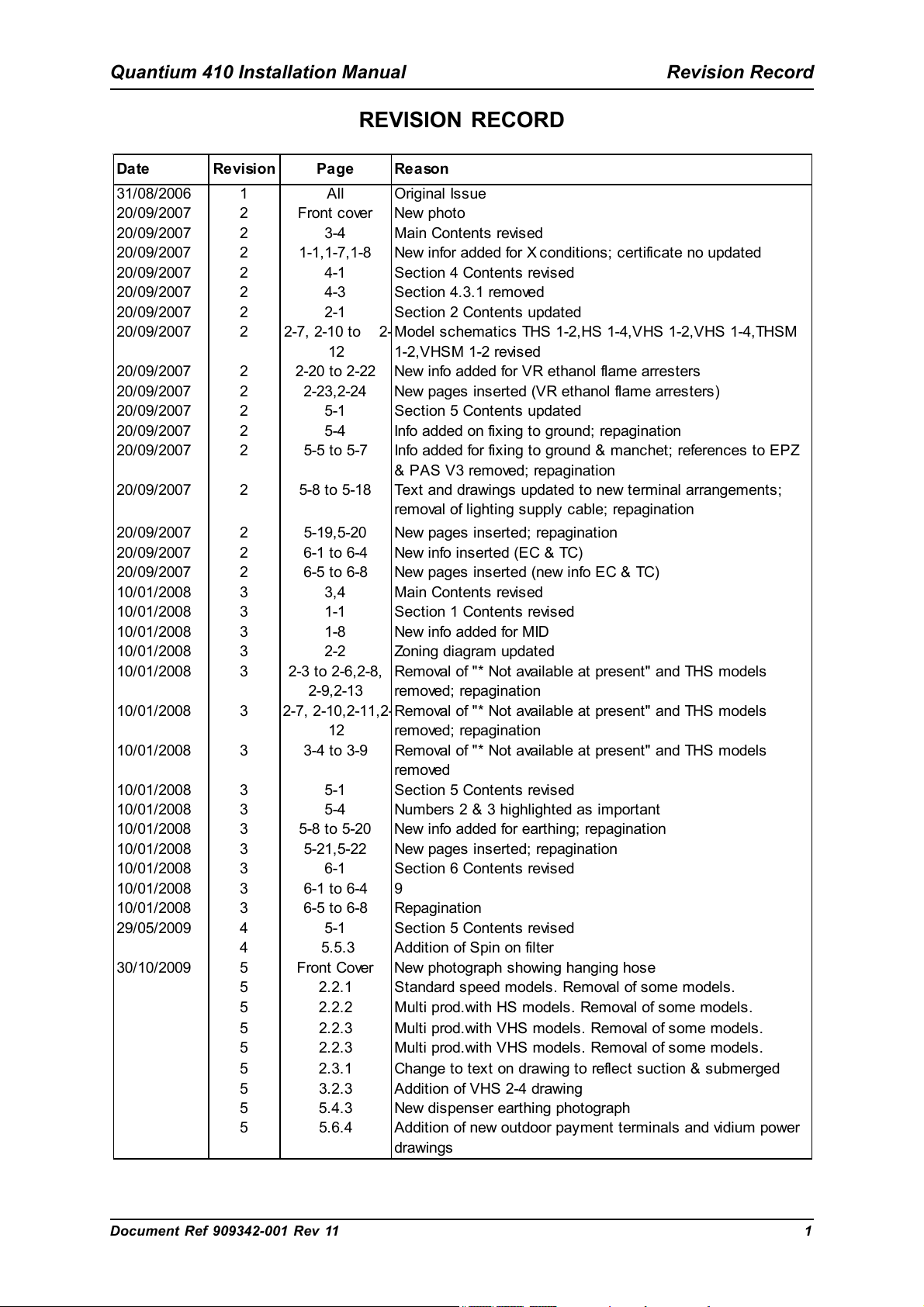
REVISION RECORD
Date Revision Page Reason
31/08/2006 1 All Original Issue
20/09/2007 2 Front cover New photo
20/09/2007 2 3-4 Main Contents revised
20/09/2007 2 1-1,1-7,1-8 New infor added for X conditions; certificate no updated
20/09/2007 2 4-1 Section 4 Contents revised
20/09/2007 2 4-3 Section 4.3.1 removed
20/09/2007 2 2-1 Section 2 Contents updated
20/09/2007 2 2-7, 2-10 to 2
12
20/09/2007 2 2-20 to 2-22 New info added for VR ethanol flame arresters
20/09/2007 2 2-23,2-24 New pages inserted (VR ethanol flame arresters)
20/09/2007 2 5-1 Section 5 Contents updated
20/09/2007 2 5-4 Info added on fixing to ground; repagination
20/09/2007 2 5-5 to 5-7 Info added for fixing to ground & manchet; references to EPZ
20/09/2007 2 5-8 to 5-18 Text and drawings updated to new terminal arrangements;
20/09/2007 2 5-19,5-20 New pages inserted; repagination
20/09/2007 2 6-1 to 6-4 New info inserted (EC & TC)
20/09/2007 2 6-5 to 6-8 New pages inserted (new info EC & TC)
10/01/2008 3 3,4 Main Contents revised
10/01/2008 3 1-1 Section 1 Contents revised
10/01/2008 3 1-8 New info added for MID
10/01/2008 3 2-2 Zoning diagram updated
10/01/2008 3 2-3 to 2-6,2-8,
2-9,2-13
10/01/2008 3 2-7, 2-10,2-11,2
12
10/01/2008 3 3-4 to 3-9 Removal of "* Not available at present" and THS models
10/01/2008 3 5-1 Section 5 Contents revised
10/01/2008 3 5-4 Numbers 2 & 3 highlighted as important
10/01/2008 3 5-8 to 5-20 New info added for earthing; repagination
10/01/2008 3 5-21,5-22 New pages inserted; repagination
10/01/2008 3 6-1 Section 6 Contents revised
10/01/2008 3 6-1 to 6-4 9
10/01/2008 3 6-5 to 6-8 Repagination
29/05/2009 4 5-1 Section 5 Contents revised
4 5.5.3 Addition of Spin on filter
30/10/2009 5 Front Cover New photograph showing hanging hose
5 2.2.1 Standard speed models. Removal of some models.
5 2.2.2 Multi prod.with HS models. Removal of some models.
5 2.2.3 Multi prod.with VHS models. Removal of some models.
5 2.2.3 Multi prod.with VHS models. Removal of some models.
5 2.3.1 Change to text on drawing to reflec t suction & submerged
5 3.2.3 Addition of VHS 2-4 drawing
5 5.4.3 New dispenser earthing photograph
5 5.6.4 Addition of new outdoor pay ment terminals and vidium power
Model schematics THS 1-2,HS 1-4,VHS 1-2,VHS 1-4,THSM
1-2,VHSM 1-2 revised
& PAS V3 removed; repagination
removal of lighting supply cable; repagination
Removal of "* Not available at present" and THS models
removed; repagination
Removal of "* Not available at present" and THS models
removed; repagination
removed
drawings
Document Ref 909342-001 Rev 11 1
Page 4
Revision Record Quantium 410 Installation Manual
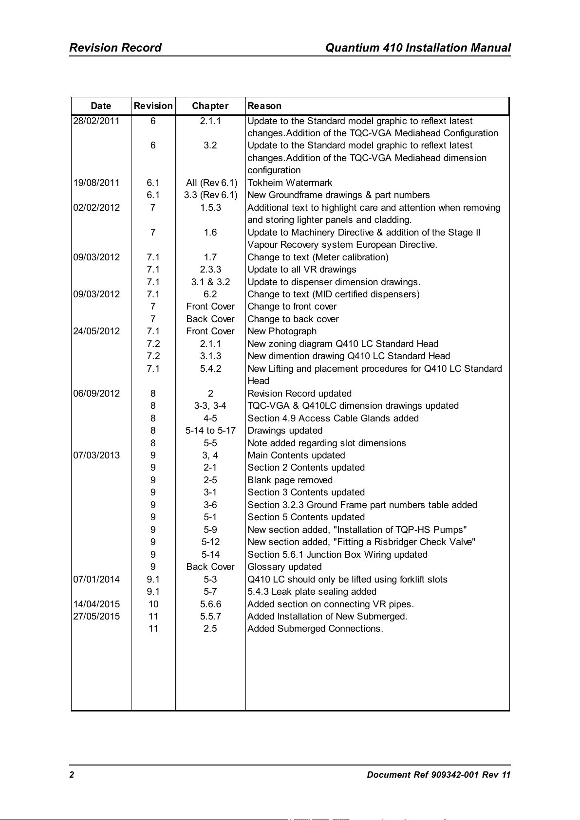
Date Revision Chapter Reason
28/02/2011 6 2.1.1 Update to the Standard model graphic to reflext latest
changes .Addition of the TQC-VGA Mediahead Configuration
6 3.2 Update to the Standard model graphic to reflext latest
changes .Addition of the TQC-VGA Mediahead dimension
configuration
19/08/2011 6.1 All (Rev 6.1) Tokheim Watermark
6.1 3.3 (Rev 6.1) New Groundframe drawings & part numbers
02/02/2012 7 1.5.3 Additional text to highlight care and attention when removing
and storing lighter panels and cladding.
7 1.6 Update to Machinery Directive & addition of the Stage II
Vapour Recovery sys tem European Directive.
09/03/2012 7.1 1.7 Change to text (Meter calibration)
7.1 2.3.3 Update to all VR drawings
7.1 3.1 & 3.2 Update to dispenser dimension drawings.
09/03/2012 7.1 6.2 Change to text (MID certified dispens ers)
7 Front Cover Change to front cover
7 Bac k Cover Change to bac k cover
24/05/2012 7.1 Front Cover New Photograph
7.2 2.1.1 New zoning diagram Q410 LC Standard Head
7.2 3.1.3 New dimention drawing Q410 LC Standard Head
7.1 5.4.2 New Lifting and placement procedures for Q410 LC Standard
Head
06/09/2012 8 2 Revision Record updated
8 3-3, 3-4 TQC-VGA & Q410LC dimension drawings updated
8 4-5 Section 4.9 Access Cable Glands added
8 5-14 to 5-17 Drawings updated
8 5-5 Note added regarding slot dimensions
07/03/2013 9 3, 4 Main Contents updated
9 2-1 Section 2 Contents updated
9 2-5 Blank page removed
9 3-1 Section 3 Contents updated
9 3-6 Section 3.2.3 Ground Frame part numbers table added
9 5-1 Section 5 Contents updated
9 5-9 New section added, "Installation of TQP-HS Pumps"
9 5-12 New section added, "Fitting a Risbridger Check Valve"
9 5-14 Section 5.6.1 Junction Box W iring updated
9 Bac k Cover Glossary updated
07/01/2014 9.1 5-3 Q410 LC should only be lifted using forklift slots
9.1 5-7 5.4.3 Leak plate sealing added
14/04/2015 10 5.6.6 Added section on connecting VR pipes.
27/05/2015 11 5.5.7 Added Installation of New Submerged.
11 2.5 Added Submerged Connections .
2 Document Ref 909342-001 Rev 11
Page 5
Quantium 410 Installation Manual Contents
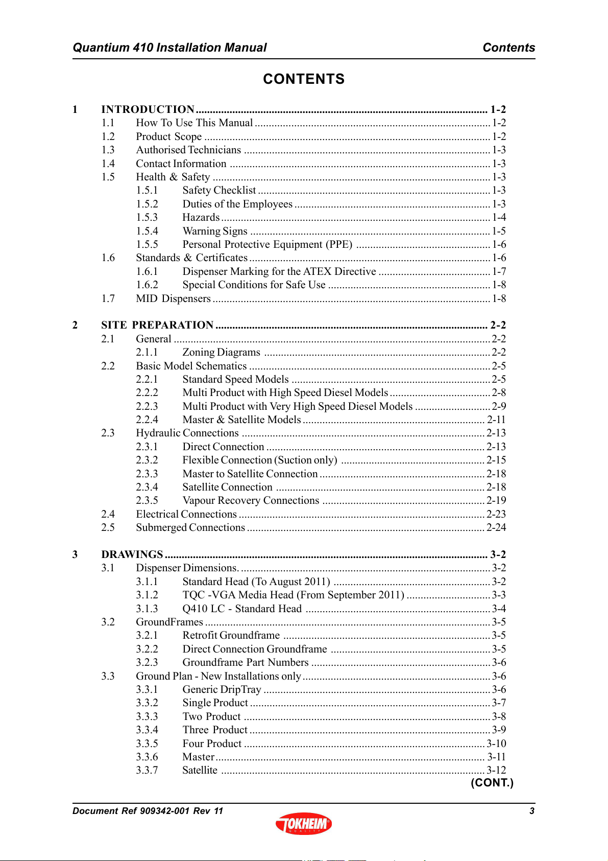
CONTENTS
1 INTRODUCTION........................................................................................................ 1-2
1.1 How To Use This Manual .................................................................................... 1-2
1.2 Product Scope ......................................................................................................1-2
1.3 Authorised Technicians ........................................................................................ 1-3
1.4 Contact Information ............................................................................................. 1-3
1.5 Health & Safety ................................................................................................... 1-3
1.5.1 Safety Checklist ...................................................................................1-3
1.5.2 Duties of the Employees ...................................................................... 1-3
1.5.3 Hazards ................................................................................................ 1-4
1.5.4 Warning Signs ...................................................................................... 1-5
1.5.5 Personal Protective Equipment (PPE) ................................................ 1-6
1.6 Standards & Certificates ...................................................................................... 1-6
1.6.1 Dispenser Marking for the ATEX Directive ........................................ 1-7
1.6.2 Special Conditions for Safe Use ..........................................................1-8
1.7 MID Dispensers ................................................................................................... 1-8
2 SITE PREPARATION ................................................................................................. 2-2
2.1 General .................................................................................................................2-2
2.1.1 Zoning Diagrams ................................................................................. 2-2
2.2 Basic Model Schematics ......................................................................................2-5
2.2.1 Standard Speed Models .......................................................................2-5
2.2.2 Multi Product with High Speed Diesel Models .................................... 2-8
2.2.3 Multi Product with Very High Speed Diesel Models ...........................2-9
2.2.4 Master & Satellite Models ................................................................. 2-11
2.3 Hydraulic Connections ....................................................................................... 2-13
2.3.1 Direct Connection .............................................................................. 2-13
2.3.2 Flexible Connection (Suction only) .................................................... 2-15
2.3.3 Master to Satellite Connection ........................................................... 2-18
2.3.4 Satellite Connection ........................................................................... 2-18
2.3.5 Vapour Recovery Connections .......................................................... 2-19
2.4 Electrical Connections ........................................................................................2-23
2.5 Submerged Connections .....................................................................................2-24
3 DRAWINGS ................................................................................................................... 3-2
3.1 Dispenser Dimensions. .........................................................................................3-2
3.1.1 Standard Head (To August 2011) ........................................................3-2
3.1.2 TQC -VGA Media Head (From September 2011) ..............................3-3
3.1.3 Q410 LC - Standard Head .................................................................. 3-4
3.2 GroundFrames ...................................................................................................... 3-5
3.2.1 Retrofit Groundframe .......................................................................... 3-5
3.2.2 Direct Connection Groundframe ......................................................... 3-5
3.2.3 Groundframe Part Numbers ................................................................3-6
3.3 Ground Plan - New Installations only................................................................... 3-6
3.3.1 Generic DripTray .................................................................................3-6
3.3.2 Single Product ......................................................................................3-7
3.3.3 Two Product ........................................................................................3-8
3.3.4 Three Product ...................................................................................... 3-9
3.3.5 Four Product ......................................................................................3-10
3.3.6 Master................................................................................................ 3-11
3.3.7 Satellite .............................................................................................. 3-12
(CONT.)
Document Ref 909342-001 Rev 11 3
Page 6
Contents Quantium 410 Installation Manual
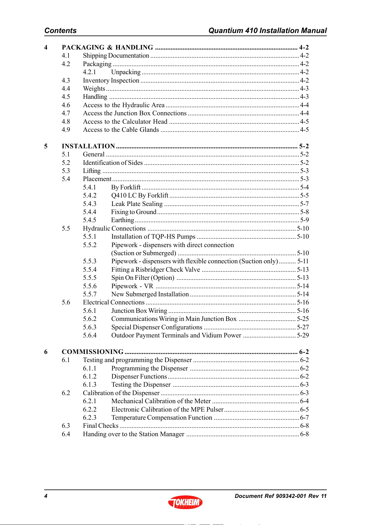
4 PACKAGING & HANDLING ................................................................................... 4-2
4.1 Shipping Documentation ....................................................................................... 4-2
4.2 Packaging .............................................................................................................4-2
4.2.1 Unpacking ............................................................................................ 4-2
4.3 Inventory Inspection .............................................................................................4-2
4.4 Weights .................................................................................................................4-3
4.5 Handling ............................................................................................................... 4-3
4.6 Access to the Hydraulic Area.............................................................................. 4-4
4.7 Access the Junction Box Connections .................................................................4-4
4.8 Access to the Calculator Head ............................................................................ 4-5
4.9 Access to the Cable Glands .................................................................................4-5
5 INSTALLATION.......................................................................................................... 5-2
5.1 General .................................................................................................................5-2
5.2 Identification of Sides ...........................................................................................5-2
5.3 Lifting ...................................................................................................................5-3
5.4 Placement............................................................................................................. 5-3
5.4.1 By Forklift ............................................................................................ 5-4
5.4.2 Q410 LC By Forklift ............................................................................5-5
5.4.3 Leak Plate Sealing ...............................................................................5-7
5.4.4 Fixing to Ground ...................................................................................5-8
5.4.5 Earthing ................................................................................................5-9
5.5 Hydraulic Connections ....................................................................................... 5-10
5.5.1 Installation of TQP-HS Pumps ..........................................................5-10
5.5.2 Pipework - dispensers with direct connection
(Suction or Submerged) ..................................................................... 5-10
5.5.3 Pipework - dispensers with flexible connection (Suction only) .......... 5-11
5.5.4 Fitting a Risbridger Check Valve ....................................................... 5-13
5.5.5 Spin On Filter (Option) ...................................................................... 5-13
5.5.6 Pipework - VR .................................................................................. 5-14
5.5.7 New Submerged Installation ..............................................................5-14
5.6 Electrical Connections ........................................................................................5-16
5.6.1 Junction Box Wiring ........................................................................... 5-16
5.6.2 Communications Wiring in Main Junction Box .................................. 5-25
5.6.3 Special Dispenser Configurations ...................................................... 5-27
5.6.4 Outdoor Payment Terminals and Vidium Power ............................... 5-29
6 COMMISSIONING ..................................................................................................... 6-2
6.1 Testing and programming the Dispenser ..............................................................6-2
6.1.1 Programming the Dispenser ................................................................ 6-2
6.1.2 Dispenser Functions............................................................................. 6-2
6.1.3 Testing the Dispenser .......................................................................... 6-3
6.2 Calibration of the Dispenser .................................................................................6-3
6.2.1 Mechanical Calibration of the Meter ...................................................6-4
6.2.2 Electronic Calibration of the MPE Pulser............................................ 6-5
6.2.3 Temperature Compensation Function .................................................. 6-7
6.3 Final Checks .........................................................................................................6-8
6.4 Handing over to the Station Manager .................................................................. 6-8
4 Document Ref 909342-001 Rev 11
Page 7
Quantium 410 Installation Manual Introduction
CONTENTS
1 INTRODUCTION ...........................................................................................................1-2
1.1 How To Use This Manual .................................................................................... 1-2
1.2 Product Scope ......................................................................................................1-2
1.3 Authorised Technicians .........................................................................................1-3
1.4 Contact Information ..............................................................................................1-3
1.5 Health & Safety ....................................................................................................1-3
1.5.1 Safety Checklist ...................................................................................1-3
1.5.2 Duties of the Employees ...................................................................... 1-3
1.5.3 Hazards ................................................................................................ 1-4
1.5.4 Warning Signs ......................................................................................1-5
1.5.5 Personal Protective Equipment (PPE) .................................................1-6
1.6 Standards & Certificates ....................................................................................... 1-6
1.6.1 Dispenser Marking for the ATEX Directive .......................................... 1-7
1.6.2 Special Conditions for Safe Use ........................................................... 1-8
1.7 MID Dispensers ....................................................................................................1-8
Document Ref 909342-001 Rev 11 Page 1-1
Page 8
Introduction Quantium 410 Installation Manual
1 INTRODUCTION
1.1 How To Use This Manual
It is recommended that all relevant persons familiarise themselves with the contents of this
manual prior to carrying out any operations or procedures.
This manual is divided into sections which are described as follows: -
Section 1 - Introduction
This section contains information on how to use the manual, the scope of equipment covered,
recommendations on qualified technicians and contact information. It also includes relevant
health and safety information required for the safe installation and commissioning of the
product.
Section 2 - Site Preparation
This section details the procedures to be carried out in preparation for receipt of equipment
at site and the necessary actions prior to installation.
Section 3 - Drawings
All necessary drawings required for reference during the installation and commissioning
are listed and contained in this section.
Section 4 - Packaging and Handling
This section provides instructions for unpacking and safe handling of the equipment
including access to the hydraulic and calculator areas.
Section 5 - Installation
The instructions for the correct installation of the equipment are contained within this
section.
Section 6 - Commissioning
This section highlights the actions and checks, to be carried out, in preparation for the
commissioning activity and the procedures required from commissioning of the equipment
to handover.
1.2 Product Scope
The equipment and models covered by the contents of this manual are: -
The Quantium 410 range of fuel dispensers, with the exception of the LPG version. For
information on Quantium LPG dispensers refer to the relevant LPG manual as provided
by Tokheim.
All dispensers in the Quantium 410 range use the same standard sub-assemblies and offer
a wide range of configurations and includes provision for options such as integrated
payment terminal, vapour recovery etc.
Page 1-2 Document Ref 909342-001 Rev 11
Page 9

Quantium 410 Installation Manual Introduction
1.3 Authorised Technicians
Only qualified technicians familiar with the contents of this manual should carry out the
procedures contained herein.
WARNING: ANY ATTEMPTS TO CARRY OUT THE PROCEDURES OF THIS
MANUAL, BY UNQUALIFIED OR UNAUTHORISED PERSONS, MAY RESULT
IN SERIOUS INJURY OR LOSS OF LIFE.
NOTE: - THIS MANUAL IS NOT INTENDED TO REPLACE THE SERVICES
OF A FULLY QUALIFIED TECHNICIAN.
1.4 Contact Information
For information relating to the contents of this manual please contact: -
Technical Author
Tokheim UK Ltd.
Dundee, Scotland
1.5 Health & Safety
1.5.1 SAFETY CHECKLIST
• It is obligatory that this checklist be fully complied with during all work at the
petrol station, particularly construction or repair work.
• It is the duty of the contractor to ensure that all workers employed by him obey
each and all of the relevant laws, directives and other regulations.
Areas where special caution is required
• The insides of tanks, tubes, dome shafts, filling shafts, change over shafts, vessels
and dispensers.
• All areas in which fuel vapour that is heavier than air can accumulate, e.g. fuel
separator, draining shafts, low located rooms, cellars, excavations, pipe trenches
etc.
• The areas around the outlets of tank ventilation pipes, especially during the
filling phase.
• All areas near dispensers, tanker lorries and other vehicles while they are being
tanked up, and particularly when there is a lack of wind.
• A radius of 1.0 metres around petrol carrying pipes, as well as pipes that are not
vapour free.
• Silt traps.
1.5.2 DUTIES OF THE EMPLOYEES
• To ensure optimal accident prevention in our company, in addition to general
rules applying to worker’s protection, it is necessary to take into account all the
national protection of workers legislation and to actively support all measures
which enhance safety standards.
Document Ref 909342-001 Rev 11 Page 1-3
Page 10
Introduction Quantium 410 Installation Manual
• It is an employee’s duty to follow all company directives regarding the prevention
of accidents, unless such directives can be proved to be unfounded.
• Employees should not follow any instructions that go against safety standards.
• Employees are only permitted to use equipment for its original purpose, and this
is defined by the company alone.
• If an employee detects equipment that is deficient in terms of safety, he shall
eliminate this deficiency immediately. If such safety rectification is not part of
his defined area of activities, or if his knowledge is insufficient to carry out
such work he must immediately inform his superior about the detected safety
deficiency.
This equally applies to:
1) Work Materials which have not been correctly packed or correctly marked in
order to meet safety requirements.
2) Work Methods or work processes which have not been correctly coordinated
or controlled in order to meet safety requirements.
3) Where dangerous activities are carried out by several persons, the need for
a permanent faultless communication between them in order to avoid dangerous
events shall require the appointing of one person in order to carry out overall
supervision.
1.5.3 HAZARDS
Prior to starting work, the dispenser must be isolated (i.e. entirely disconnected
from the mains supply) and the mains supply switch locked in the OFF position.
The submerged pump (if applicable) and control signals from the dispenser
must also be isolated. This is done to provide safety for the technician. As a
further precaution, switch off the mains supply in the service station shop and
place a clear notice on the switch to avoid it being turned on again inadvertently.
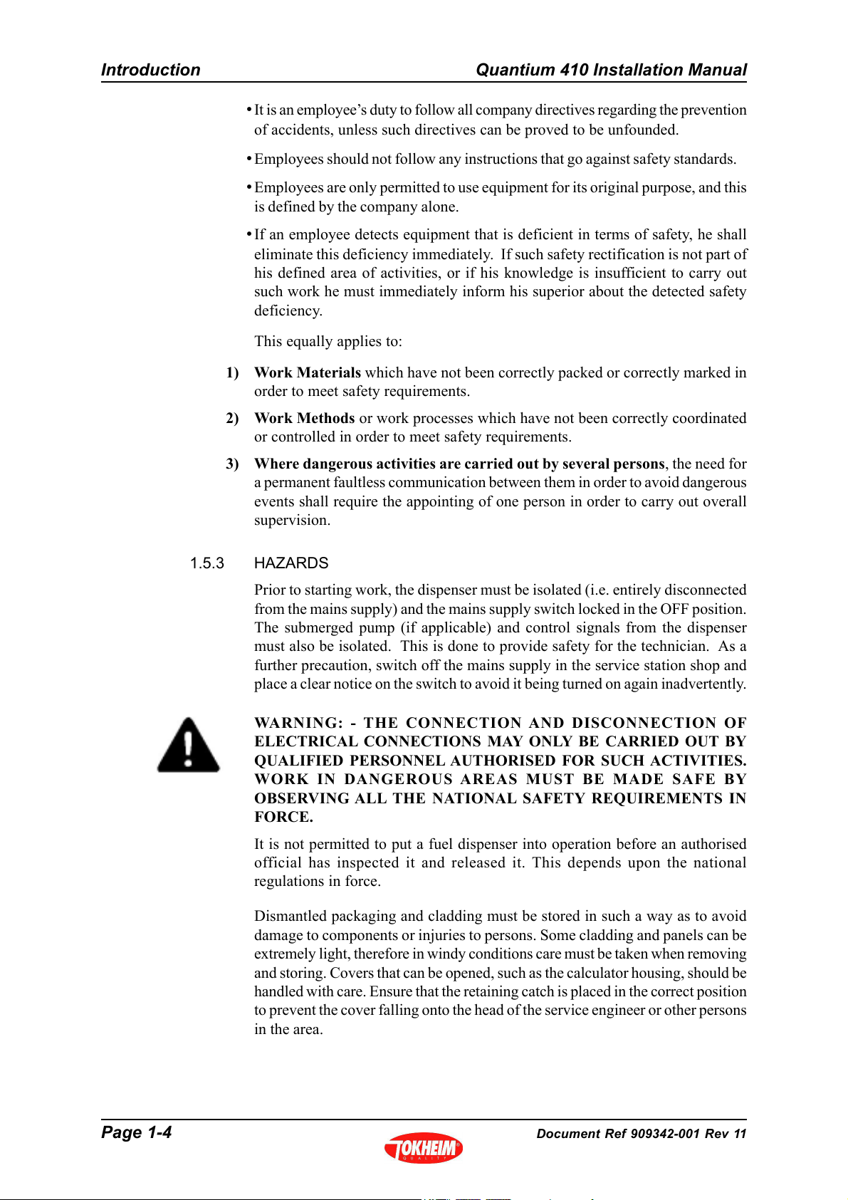
WARNING: - THE CONNECTION AND DISCONNECTION OF
ELECTRICAL CONNECTIONS MAY ONLY BE CARRIED OUT BY
QUALIFIED PERSONNEL AUTHORISED FOR SUCH ACTIVITIES.
WORK IN DANGEROUS AREAS MUST BE MADE SAFE BY
OBSERVING ALL THE NATIONAL SAFETY REQUIREMENTS IN
FORCE.
It is not permitted to put a fuel dispenser into operation before an authorised
official has inspected it and released it. This depends upon the national
regulations in force.
Dismantled packaging and cladding must be stored in such a way as to avoid
damage to components or injuries to persons. Some cladding and panels can be
extremely light, therefore in windy conditions care must be taken when removing
and storing. Covers that can be opened, such as the calculator housing, should be
handled with care. Ensure that the retaining catch is placed in the correct position
to prevent the cover falling onto the head of the service engineer or other persons
in the area.
Page 1-4 Document Ref 909342-001 Rev 11
Page 11
Quantium 410 Installation Manual Introduction
At unattended service stations, every end-user should be able to read the User
Instructions. They should be visible on a notice board or integrated into the DIT
and should be sufficiently well lit so that they can be read at night.
At unattended service stations break away couplings must always be used to
reduce the danger caused by a motorist driving off with the nozzle still in the
tank.
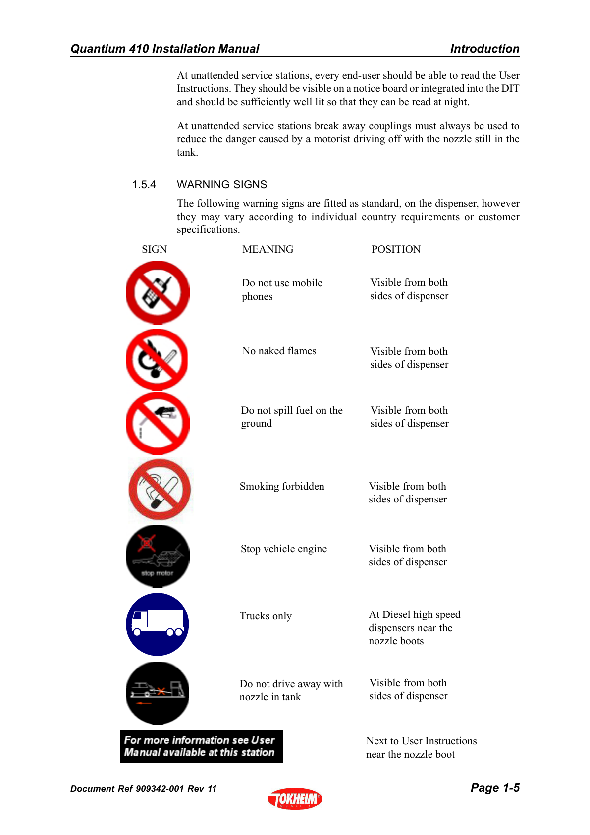
1.5.4 WARNING SIGNS
The following warning signs are fitted as standard, on the dispenser, however
they may vary according to individual country requirements or customer
specifications.
SIGN
MEANING POSITION
Do not use mobile
phones
No naked flames
Visible from both
sides of dispenser
Visible from both
sides of dispenser
Do not spill fuel on the
ground
Smoking forbidden
Visible from both
sides of dispenser
Visible from both
sides of dispenser
Stop vehicle engine Visible from both
sides of dispenser
Trucks only
At Diesel high speed
dispensers near the
nozzle boots
Do not drive away with
nozzle in tank
Visible from both
sides of dispenser
Next to User Instructions
near the nozzle boot
Document Ref 909342-001 Rev 11 Page 1-5
Page 12

Introduction Quantium 410 Installation Manual
1.5.5 PERSONAL PROTECTIVE EQUIPMENT (PPE)
PROTECTIVE CLOTHING
The following clothing should be worn at all times during installation and
maintenance procedures:-
• Protective helmet.
• Protective shoes (conductive).
• Protective gloves and/or protective hand cream.
• Anti static clothing.
• Eye protection.
SAFETY EQUIPMENT FOR WORKING IN HAZARDOUS AREAS
The following safety equipment is required for working in hazardous areas:-
• Only spark free tools are permitted for work on dispensers.
• Work on bearings is only permitted using the standard workshop tools authorised
for this kind of work.
• The use of all electrical tools is strictly prohibited.
• Only the use of explosion protected work lights is permitted.
• The use of telecommunications equipment in hazardous areas is strictly
prohibited.
SAFETY INSTRUCTIONS
The following safety instructions must be adhered to during installation and
maintenance procedures:-
• Inhalation of petrol vapour must be avoided. Suitable precautions must be
taken and where necessary respirators used.
• Avoid direct contact of fuel with the skin.
• Use suitable protective clothing, protective gloves and/or protective hand cream.
• Avoid fuel spills.
• No smoking, no naked flames are permitted.
• Long hair and ties can get caught in moving parts. Hair must be suitably covered.
1.6 Standards & Certificates
This dispenser is constructed in conformity with the requirements of all the applicable
European Directives (Machinery 2006/42/EC; EMC 89/336/EEC; ATEX 94/9/EC).
The components used within the dispenser, including connection facilities, are selected in
accordance with the European Standard EN BS 60079-0 (Electrical Apparatus for explosive
gas atmospheres), and the supplementary Standards listed therein.
Diesel dispensers do not create an explosive hazard, but due to the probability of these
being in close proximity to gasoline dispensers, the same construction rules are applicable.
Page 1-6 Document Ref 909342-001 Rev 11
Page 13
Quantium 410 Installation Manual Introduction
The dispenser is certified by SIRA as suitable for use in Potentially Explosive Atmospheres
Directive 94/9/EC, and marked to be in accordance with the European Dispenser Construction
Standard EN 13617-1.
This dispenser is also certified to OIML International Recommendations R117 and R118.
Certificate Numbers R117/1995-NL-01.04 & 08.
Dispensers fitted with a Stage II Vapour Recovery system, are in conformity with the
requirements of European Directive 2009/126/EC.
The production and end test is controlled through the Quality Assurance systems within the
Tokheim Manufacturing Centres, and has received Quality Assurance Notification from a
Notified Body.
No modification to the dispenser may be performed without express permission from Tokheim
and must always use original components or Tokheim retrofit kits. Failure to comply with
the above will invalidate product conformance with the relevant European Directives and
Tokheim will no longer accept product liability.
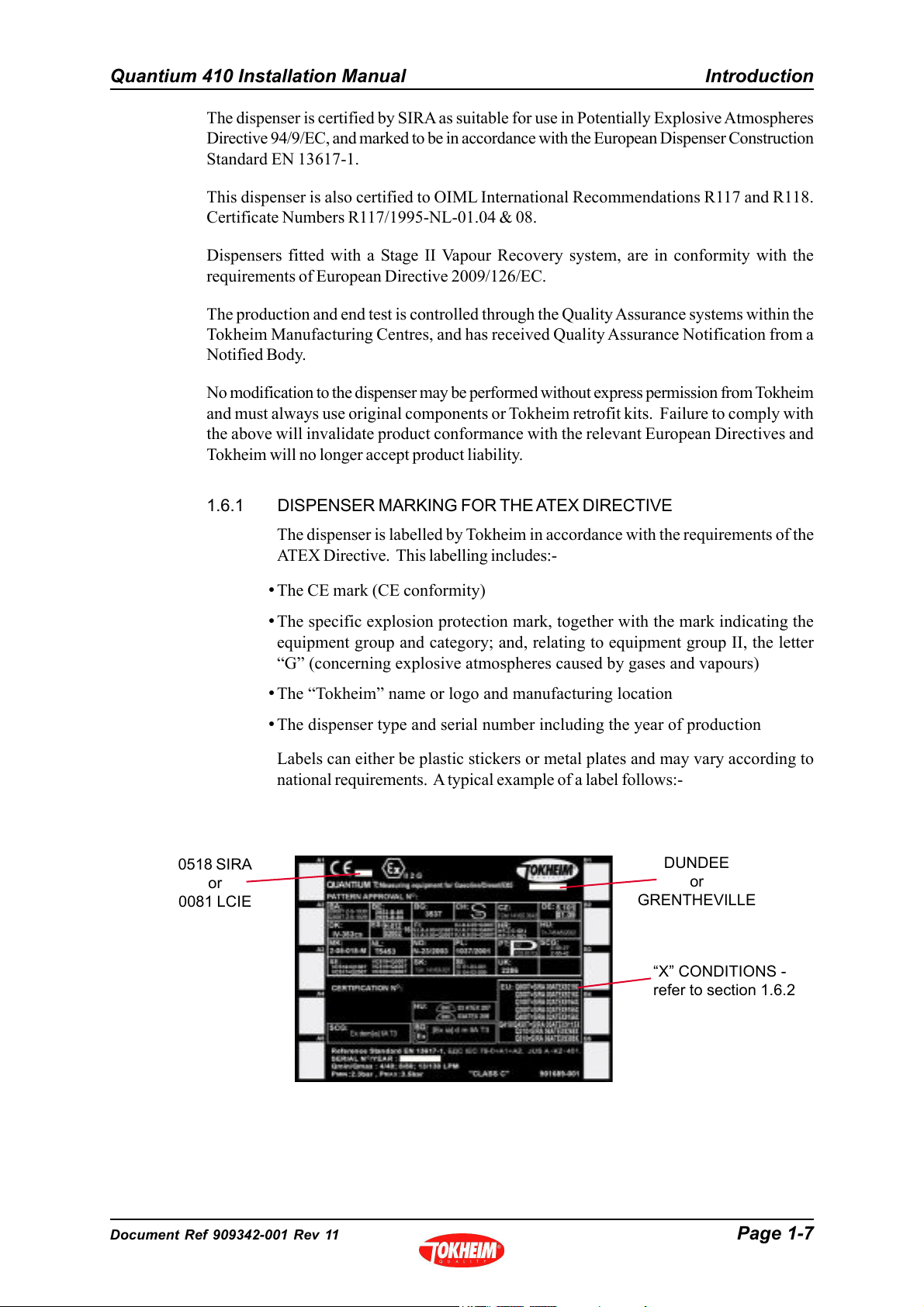
1.6.1 DISPENSER MARKING FOR THE ATEX DIRECTIVE
0518 SIRA
or
0081 LCIE
The dispenser is labelled by Tokheim in accordance with the requirements of the
ATEX Directive. This labelling includes:-
• The CE mark (CE conformity)
• The specific explosion protection mark, together with the mark indicating the
equipment group and category; and, relating to equipment group II, the letter
“G” (concerning explosive atmospheres caused by gases and vapours)
• The “Tokheim” name or logo and manufacturing location
• The dispenser type and serial number including the year of production
Labels can either be plastic stickers or metal plates and may vary according to
national requirements. A typical example of a label follows:-
DUNDEE
or
GRENTHEVILLE
“X” CONDITIONS -
refer to section 1.6.2
Document Ref 909342-001 Rev 11 Page 1-7
Page 14
Introduction Quantium 410 Installation Manual
1.6.2 SPECIAL CONDITIONS FOR SAFE USE
Certain models include Special Conditions for Safe Use which must be observed
prior to putting the dispensers into operation. Failure to do so will invalidate the
ATEX certification of the dispenser. These models can be identified by an X at
the end of the certificate number as shown on the dispenser typeplate.
The Special Conditions for Safe Use are identified in the ATEX EC Type-
Examination Certificates and are repeated below:-
• Where a dispenser is supplied without hoses and/or nozzles, they shall be fitted
in accordance with:
- Hoses : EN1360 or EN13483
- Nozzles: EN13012
• When used for ethanol (blend) dispensing, the fuel specification must be less
than or equal to 85% ethanol, with minimum water content.
• The metering pumps and dispensers are designed for use in open air. Where a
metering pump or dispenser is positioned within a building, incorporated into an
enclosure, or integrated into a larger piece of equipment, additional measures
shall be taken to ensure that the zoning diagrams illustrated in the schedule
drawings are not compromised.
1.7 MID Dispensers
From mid 2007, Tokheim dispensers may be shipped from European factories in accordance
with the Metrological Instruments Directive (MID). Such dispensers are calibrated and the
relevant seals stamped in the factory so that the dispensers are fit for trade immediately
upon installation without the need for a local Weights and Measures inspector to put them
into use.
The dispenser is shipped with its own “MID datasheet” which documents the serial numbers
of the prime components fitted in the dispenser. This datasheet must remain with the
dispenser. Similarly dispensers are shipped with a Declaration of Conformance to the MID.
This document must not be lost as it is an essential document to allow the continued use of
the dispenser.
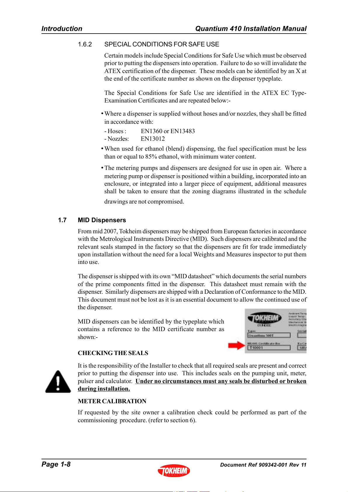
MID dispensers can be identified by the typeplate which
contains a reference to the MID certificate number as
shown:-
CHECKING THE SEALS
It is the responsibility of the Installer to check that all required seals are present and correct
prior to putting the dispenser into use. This includes seals on the pumping unit, meter,
pulser and calculator.
during installation.
Under no circumstances must any seals be disturbed or broken
METER CALIBRATION
If requested by the site owner a calibration check could be performed as part of the
commissioning procedure. (refer to section 6).
Page 1-8 Document Ref 909342-001 Rev 11
Page 15
Quantium 410 Installation Manual Site Preparation
CONTENTS
2 SITE PREPARATION ................................................................................................. 2-2
2.1 General .................................................................................................................2-2
2.1.1 Zoning Diagrams ................................................................................. 2-2
2.2 Basic Model Schematics ......................................................................................2-5
2.2.1 Standard Speed Models .......................................................................2-5
2.2.2 Multi Product with High Speed Diesel Models .................................... 2-8
2.2.3 Multi Product with Very High Speed Diesel Models ...........................2-9
2.2.4 Master & Satellite Models ................................................................. 2-11
2.3 Hydraulic Connections ....................................................................................... 2-13
2.3.1 Direct Connection .............................................................................. 2-13
2.3.2 Flexible Connection (Suction only) .................................................... 2-15
2.3.3 Master to Satellite Connection ........................................................... 2-18
2.3.4 Satellite Connection ........................................................................... 2-18
2.3.5 Vapour Recovery Connections .......................................................... 2-19
2.4 Electrical Connections ........................................................................................2-23
2.5 Submerged Connections .....................................................................................2-24
Document Ref 909342-001 Rev 11 Page 2-1
Page 16
Site Preparation Quantium 410 Installation Manual
2 SITE PREPARATION
2.1 General
Tokheim dispensers must only be installed on a level island or forecourt surface.
The ground plan will depend on the model ordered. See drawings in Section 3.
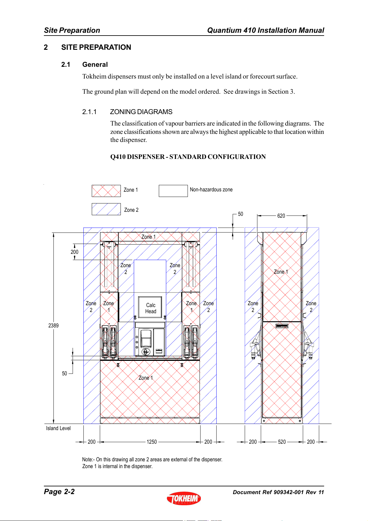
2.1.1 ZONING DIAGRAMS
The classification of vapour barriers are indicated in the following diagrams. The
zone classifications shown are always the highest applicable to that location within
the dispenser.
Q410 DISPENSER - STANDARD CONFIGURATION
2389
200
Zone
2
Zone
1
Zone 1
Zone 2
Zone
2
Zone 1
Calc
Head
Zone
2
Non-hazardous zone
Zone
Zone
1
2
50
Zone
2
620
Zone 1
Zone
2
50
Island Level
Note:- On this drawing all zone 2 areas are external of the dispenser.
Zone 1 is internal in the dispenser.
Zone 1
1250 200200
520200
200
Page 2-2 Document Ref 909342-001 Rev 11
Page 17
Quantium 410 Installation Manual Site Preparation
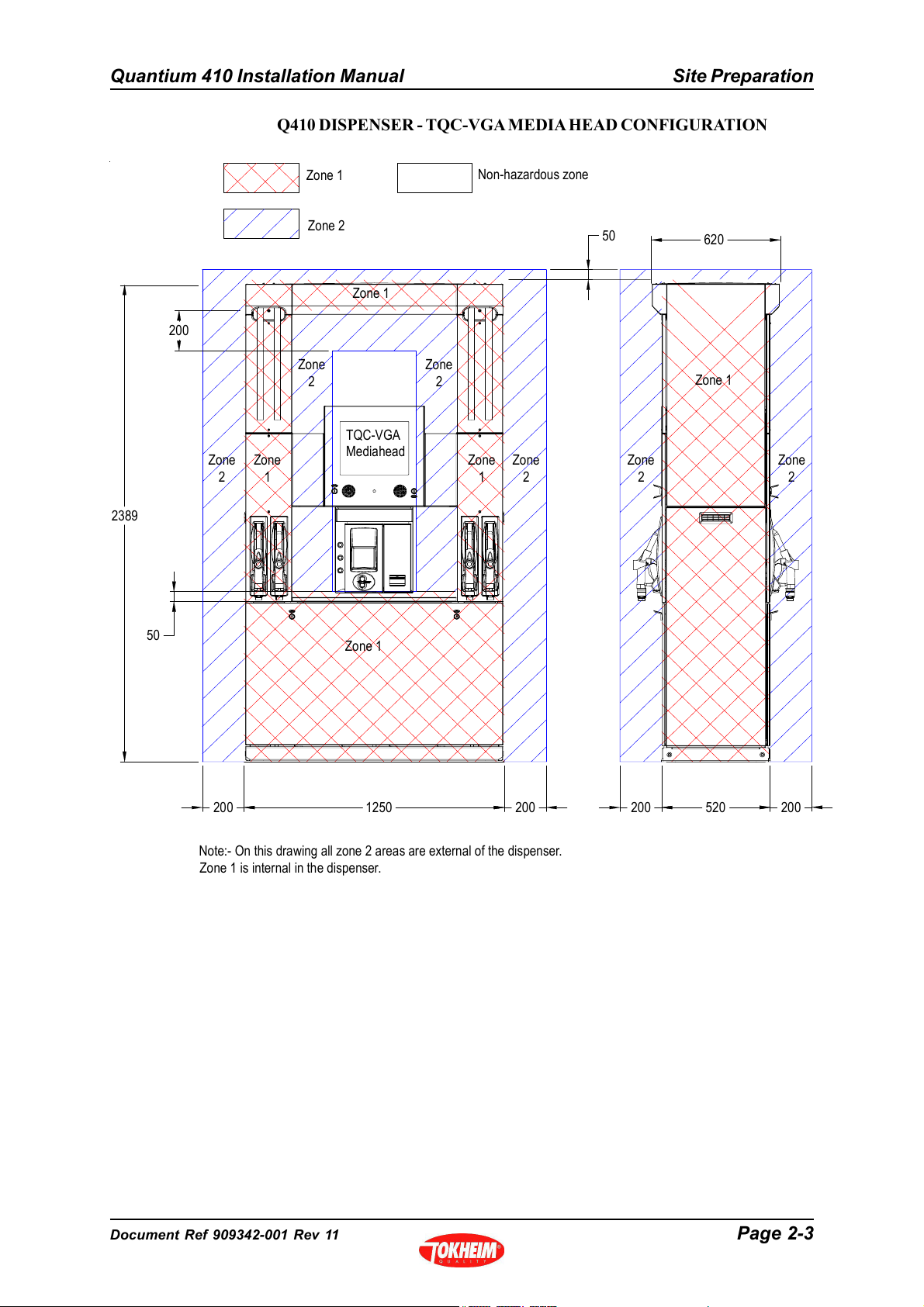
Q410 DISPENSER - TQC-VGA MEDIA HEAD CONFIGURATION
2389
200
Zone
2
Zone
1
Zone 1
Zone 2
Zone
2
Zone 1
TQC-VGA
Mediahead
Zone
2
Non-hazardous zone
Zone
Zone
1
2
50
Zone
2
620
Zone 1
Zone
2
50
Zone 1
1250 200200
Note:- On this drawing all zone 2 areas are external of the dispenser.
Zone 1 is internal in the dispenser.
520200
200
Document Ref 909342-001 Rev 11 Page 2-3
Page 18
Site Preparation Quantium 410 Installation Manual
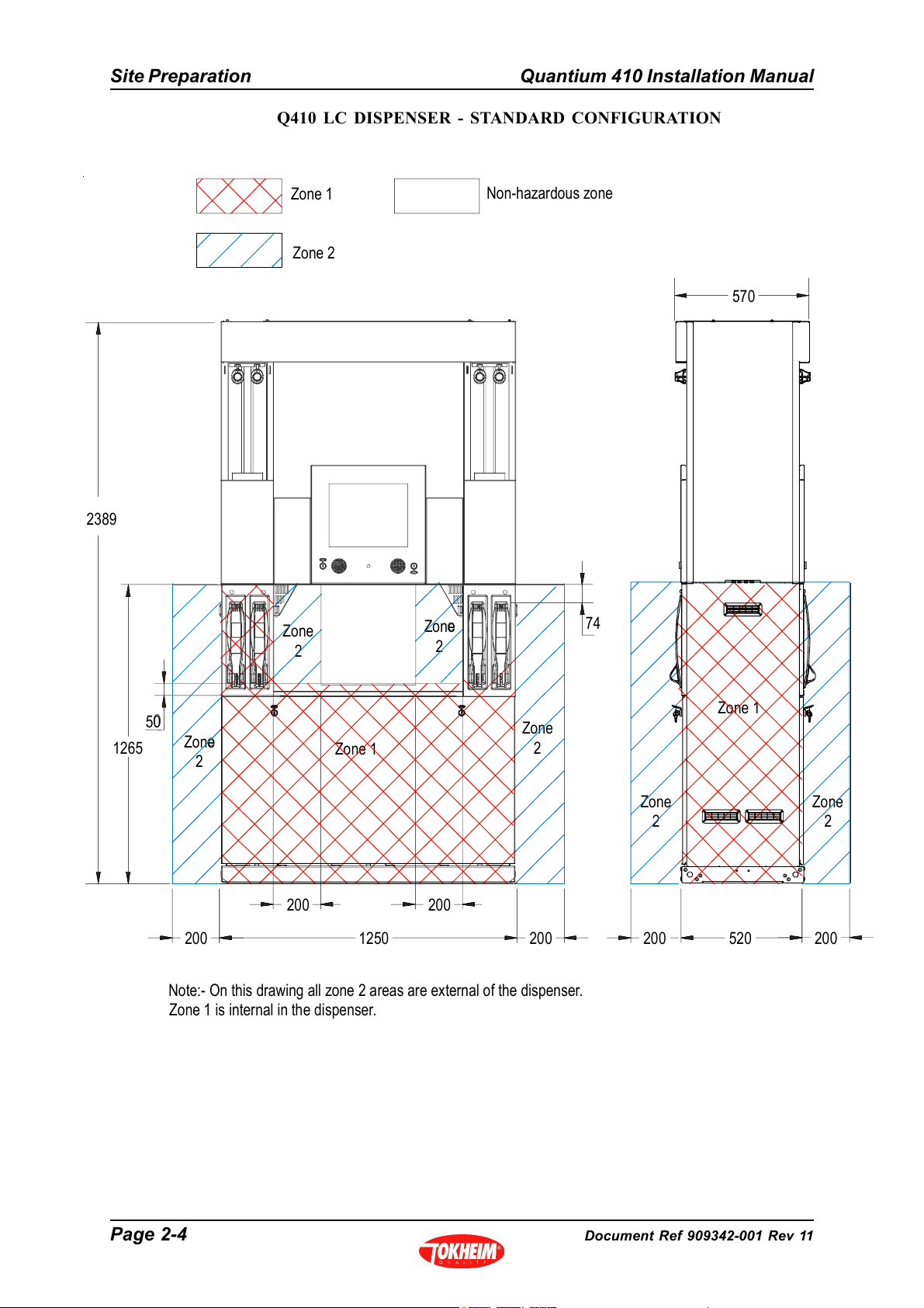
Q410 LC DISPENSER - STANDARD CONFIGURATION
2389
Zone 1
Zone 2
Zone
2
Zone
2
Non-hazardous zone
570
74
1265
50
Zone
2
200 200
Note:- On this drawing all zone 2 areas are external of the dispenser.
Zone 1 is internal in the dispenser.
Zone 1
1250 200200
Zone
2
Zone
2
Zone 1
520200
Zone
2
200
Page 2-4 Document Ref 909342-001 Rev 11
Page 19
Quantium 410 Installation Manual Site Preparation
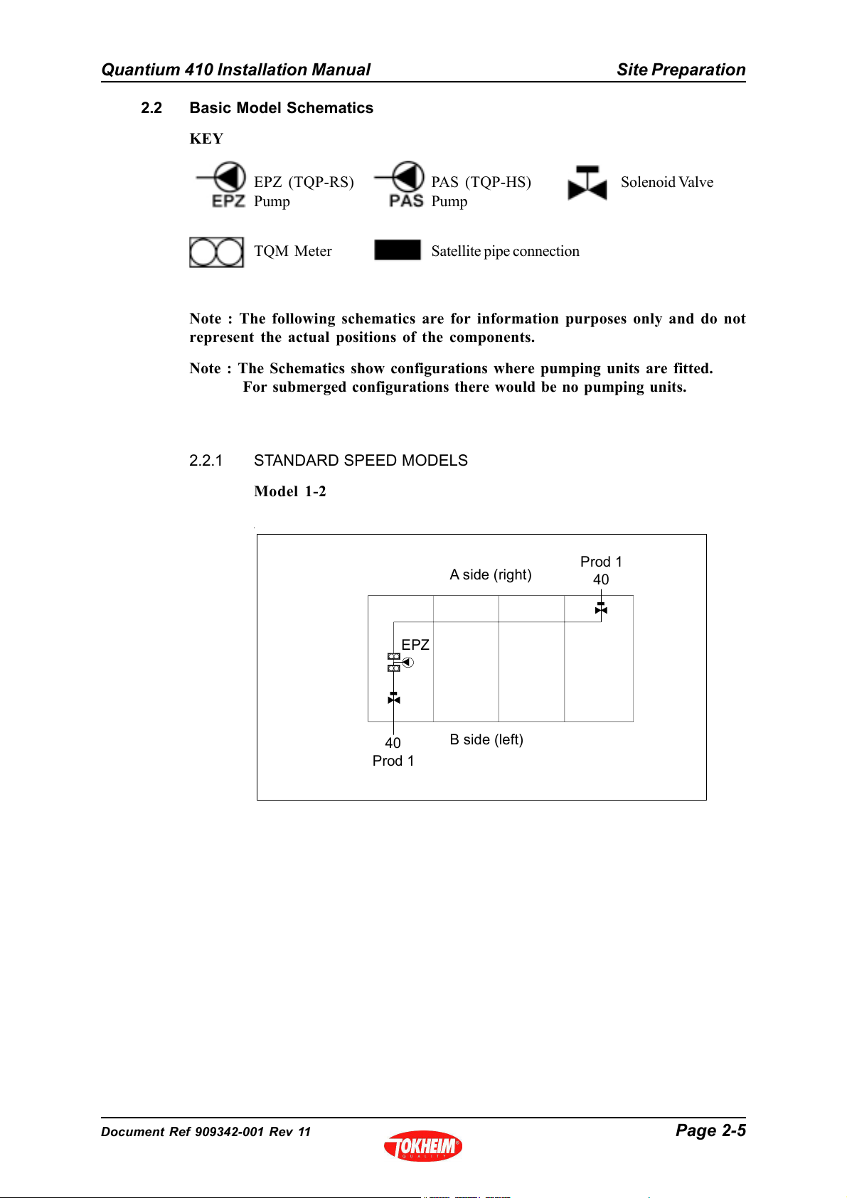
2.2 Basic Model Schematics
KEY
EPZ (TQP-RS)
Pump
TQM Meter
PAS (TQP-HS)
Pump
Satellite pipe connection
Solenoid Valve
Note : The following schematics are for information purposes only and do not
represent the actual positions of the components.
Note : The Schematics show configurations where pumping units are fitted.
For submerged configurations there would be no pumping units.
2.2.1 STANDARD SPEED MODELS
Model 1-2
A side (right)
Prod 1
40
EPZ
40
Prod 1
B side (left)
Document Ref 909342-001 Rev 11 Page 2-5
Page 20
Site Preparation Quantium 410 Installation Manual
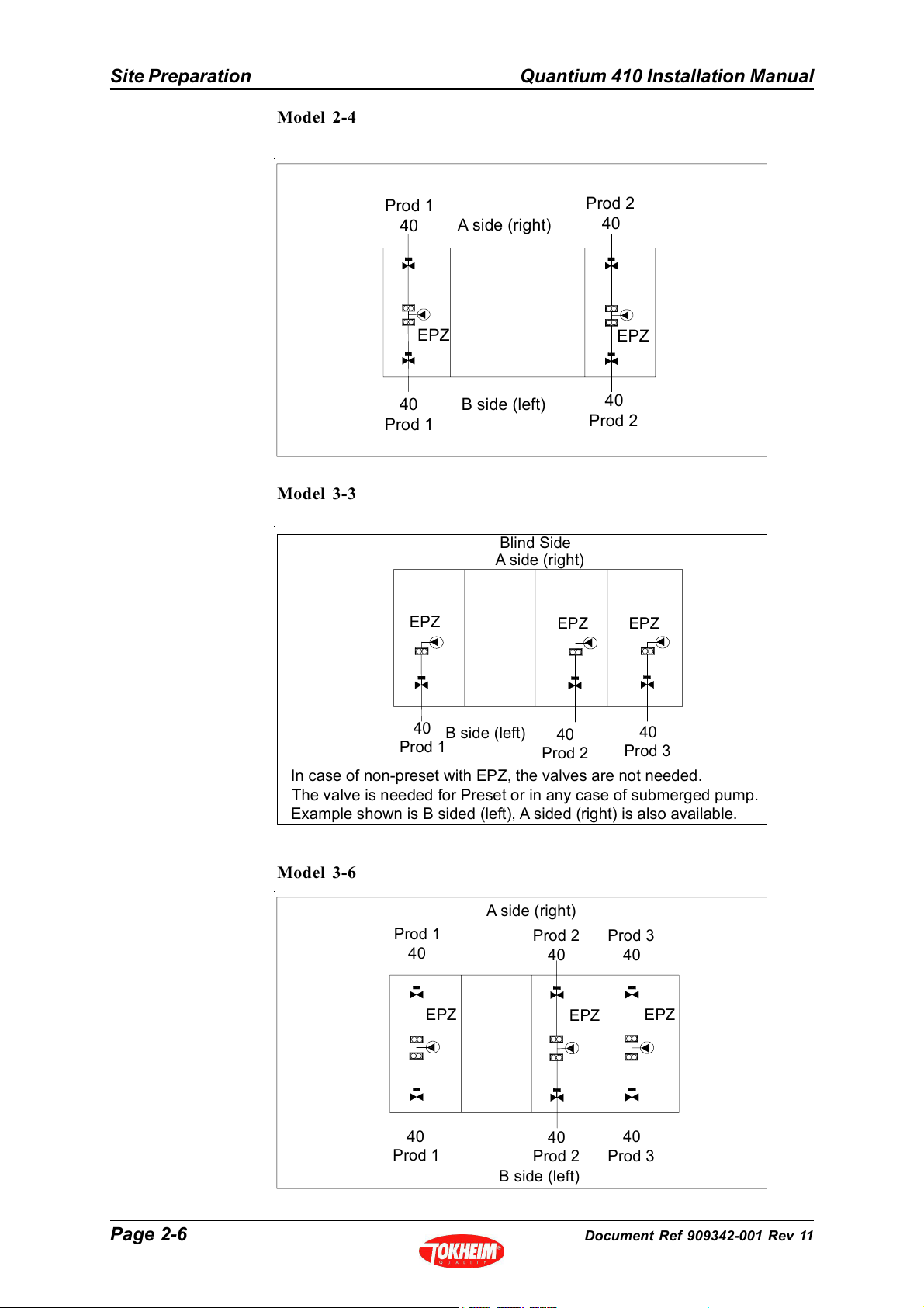
Model 2-4
Model 3-3
Prod 1
40
EPZ
40
Prod 1
EPZ
A si de (right)
B side (left)
Blind Side
A side (right)
EPZ
Prod 2
40
EPZ
40
Prod 2
EPZ
40
B side (left)
Prod 1
In case of non-preset with EPZ, the valves are not needed.
The valve is needed for Preset or in any case of submerged pump.
Example shown is B sided (left), A sided (right) is also available.
40
Prod 2
40
Prod 3
Model 3-6
A side (right)
Prod 1
40
EPZ
40
Prod 1
Prod 2
40
40
Prod 2
B side (left)
EPZ
Prod 3
40
EPZ
40
Prod 3
Page 2-6 Document Ref 909342-001 Rev 11
Page 21
Quantium 410 Installation Manual Site Preparation
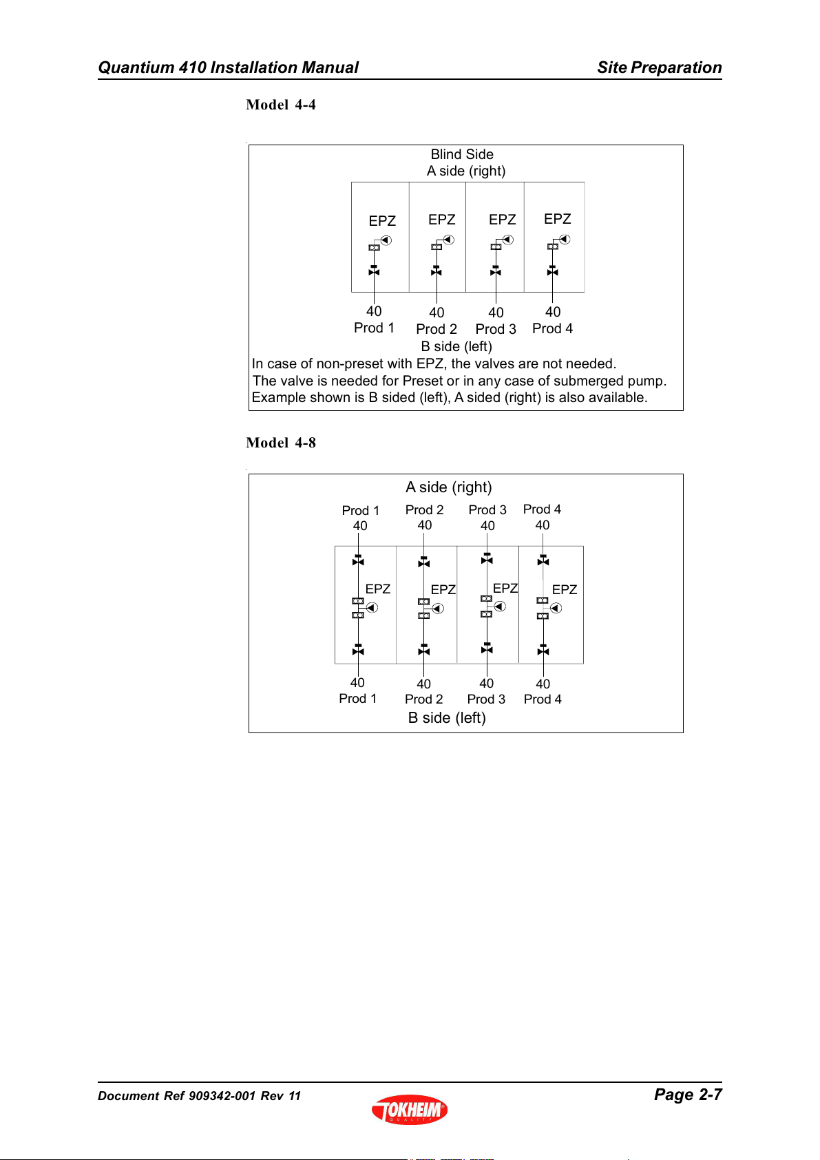
Model 4-4
Blind Side
A side (right)
EPZ
40
Prod 1
EPZ
40
Prod 2
EPZ
40
Prod 3
EPZ
40
Prod 4
B side (left)
In case of non-preset with EPZ, the valves are not needed.
The valve is needed for Preset or in any case of submerged pump.
Example shown is B sided (left), A sided (right) is also available.
Model 4-8
A side (right)
Prod 1
40
EPZ
Prod 2
40
Prod 3
40
EPZ EPZ
Prod 4
40
EPZ
40
Prod 1
40
Prod 2
Prod 3
B side (left)
40
40
Prod 4
Document Ref 909342-001 Rev 11 Page 2-7
Page 22
Site Preparation Quantium 410 Installation Manual
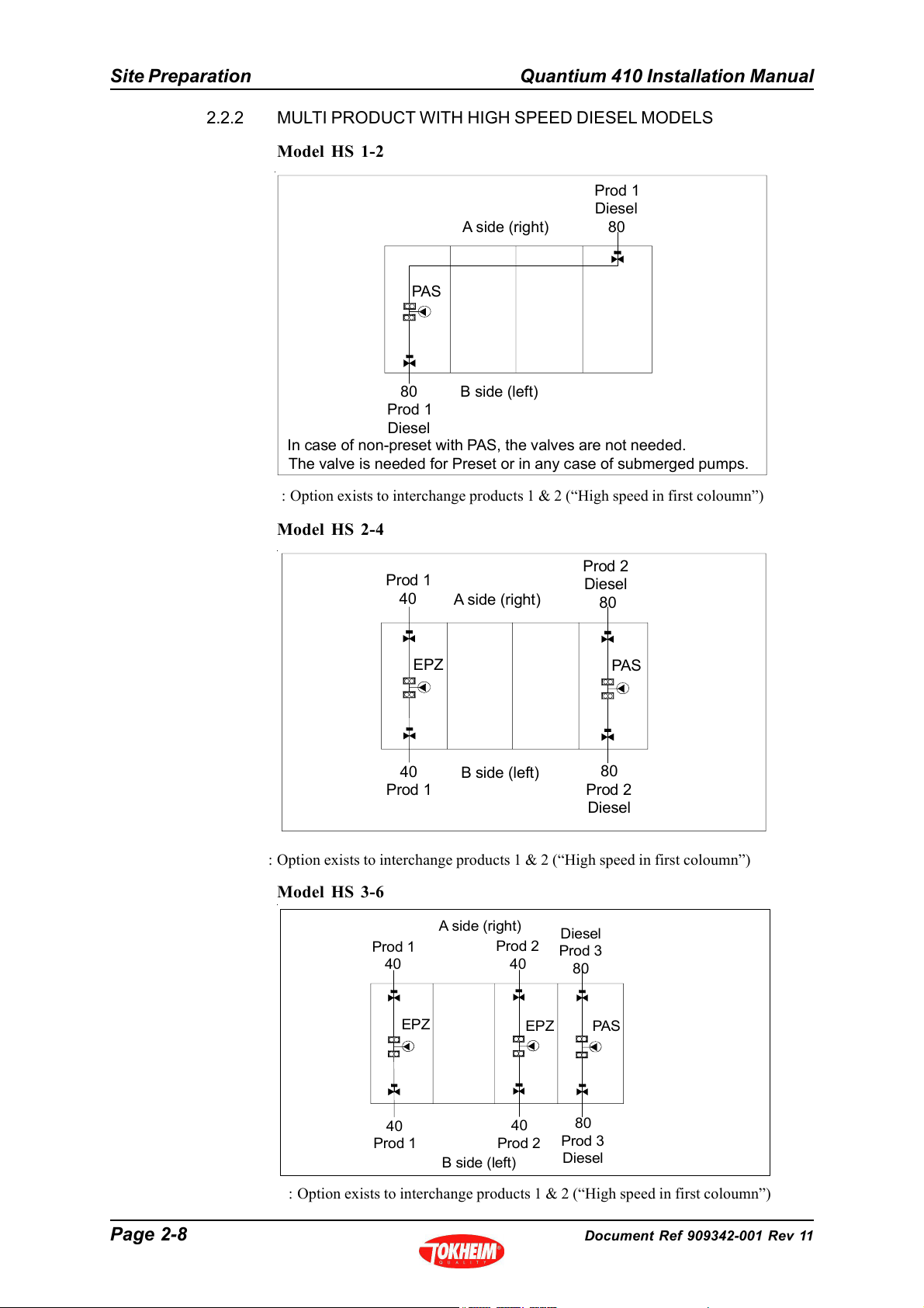
2.2.2 MULTI PRODUCT WITH HIGH SPEED DIESEL MODELS
Model HS 1-2
Prod 1
Diesel
A side (right)
PAS
80
80
Prod 1
Diesel
In case of non-preset with PAS, the valves are not needed.
The valve is needed for Preset or in any case of submerged pumps.
B side (left)
: Option exists to interchange products 1 & 2 (“High speed in first coloumn”)
Model HS 2-4
Prod 1
40
EPZ
40
Prod 1
A side (right)
B side (left)
Prod 2
Diesel
80
PAS
80
Prod 2
Diesel
: Option exists to interchange products 1 & 2 (“High speed in first coloumn”)
Model HS 3-6
A side (right)
Prod 1
40
EPZ
40
Prod 1
B side (left)
Prod 2
40
40
Prod 2
: Option exists to interchange products 1 & 2 (“High speed in first coloumn”)
EPZ
Diesel
Prod 3
80
PAS
80
Prod 3
Diesel
Page 2-8 Document Ref 909342-001 Rev 11
Page 23
Quantium 410 Installation Manual Site Preparation
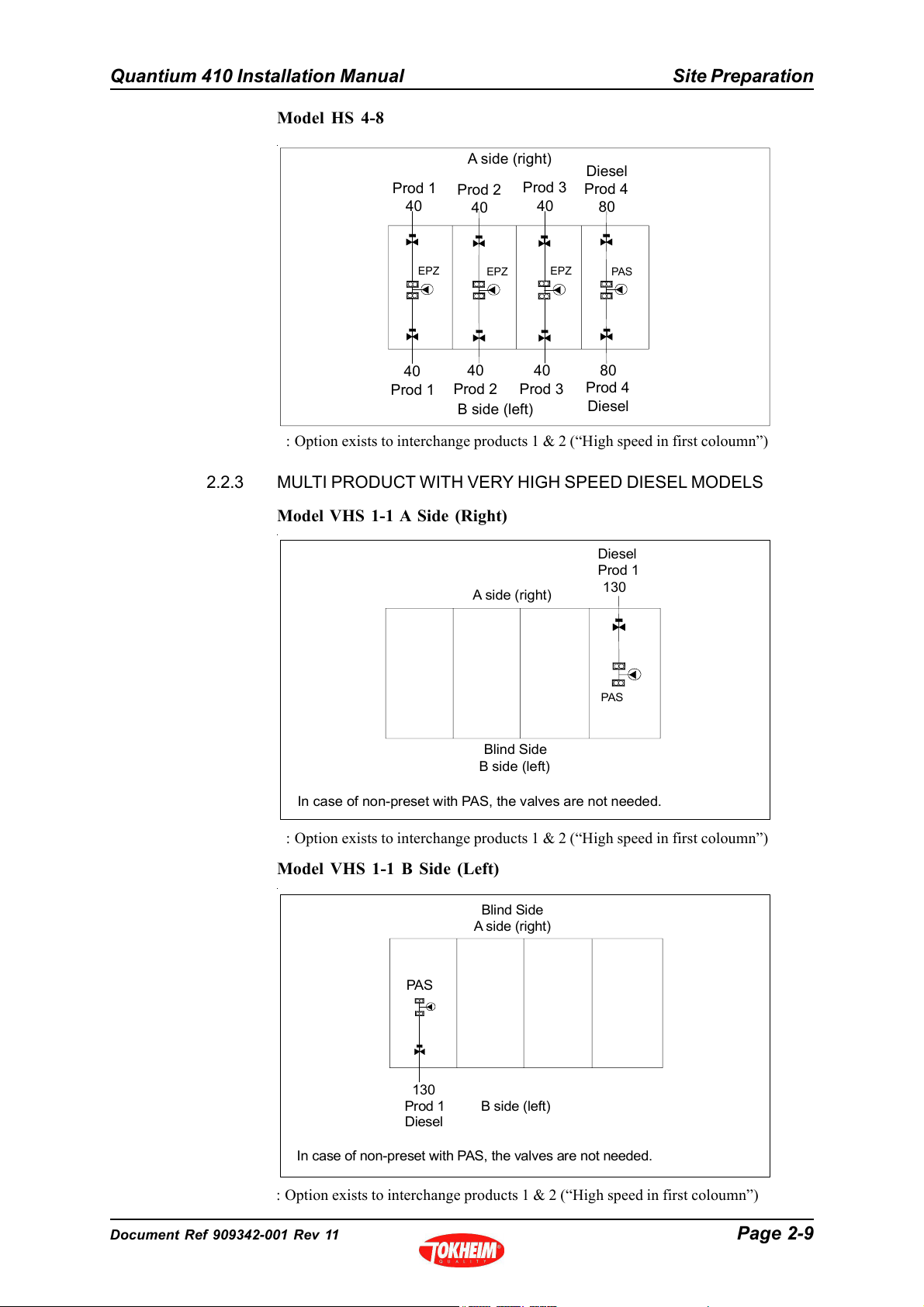
Model HS 4-8
A side (right)
Diesel
EPZ
Prod 3
40
EPZ
Prod 4
80
PAS
80
Prod 4
Diesel
Prod 1
40
EPZ
40
Prod 1
Prod 2
40
40
Prod 240Prod 3
B side (left)
: Option exists to interchange products 1 & 2 (“High speed in first coloumn”)
2.2.3 MULTI PRODUCT WITH VERY HIGH SPEED DIESEL MODELS
Model VHS 1-1 A Side (Right)
Diesel
Prod 1
A side (right )
130
PAS
Blind Side
B side (left)
In case of non-preset with PAS, the valves are not needed.
: Option exists to interchange products 1 & 2 (“High speed in first coloumn”)
Model VHS 1-1 B Side (Left)
Blind Side
A side (right)
PA S
130
Prod 1
Diesel
B side (left)
In case of non-preset with PAS, the valves are not needed.
: Option exists to interchange products 1 & 2 (“High speed in first coloumn”)
Document Ref 909342-001 Rev 11 Page 2-9
Page 24
Site Preparation Quantium 410 Installation Manual
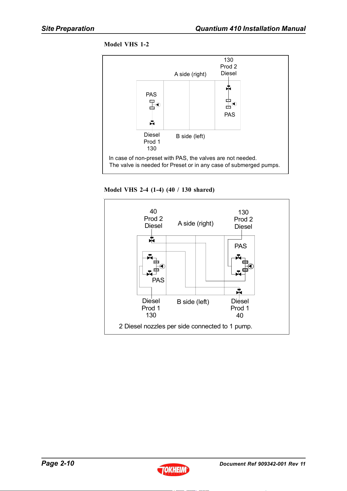
Model VHS 1-2
130
Prod 2
A side (right)
PAS
Diesel
PAS
Diesel
Prod 1
130
In case of non-preset with PAS, the valves are not needed.
The valve is needed for Preset or in any case of submerged pumps.
B side (left)
Model VHS 2-4 (1-4) (40 / 130 shared)
40
Prod 2
Diesel
A side (right)
130
Prod 2
Diesel
PAS
PAS
Diesel
Prod 1
130
B side (left)
Diesel
Prod 1
40
2 Diesel nozzles per side connected to 1 pump.
Page 2-10 Document Ref 909342-001 Rev 11
Page 25
Quantium 410 Installation Manual Site Preparation
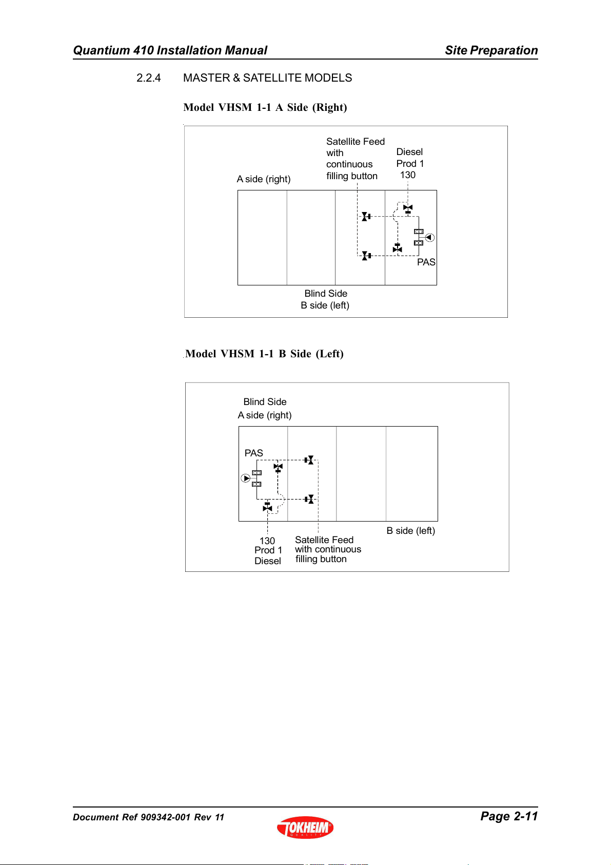
2.2.4 MASTER & SATELLITE MODELS
Model VHSM 1-1 A Side (Right)
Satellite Feed
Diesel
Prod 1
130
PAS
A side (right)
with
continuous
filling button
Blind Side
B side (left)
Model VHSM 1-1 B Side (Left)
Blind Side
A side (right)
PAS
130
Prod 1
Diesel
Satellite Feed
with continuous
filling button
B side (left)
Document Ref 909342-001 Rev 11 Page 2-11
Page 26
Site Preparation Quantium 410 Installation Manual
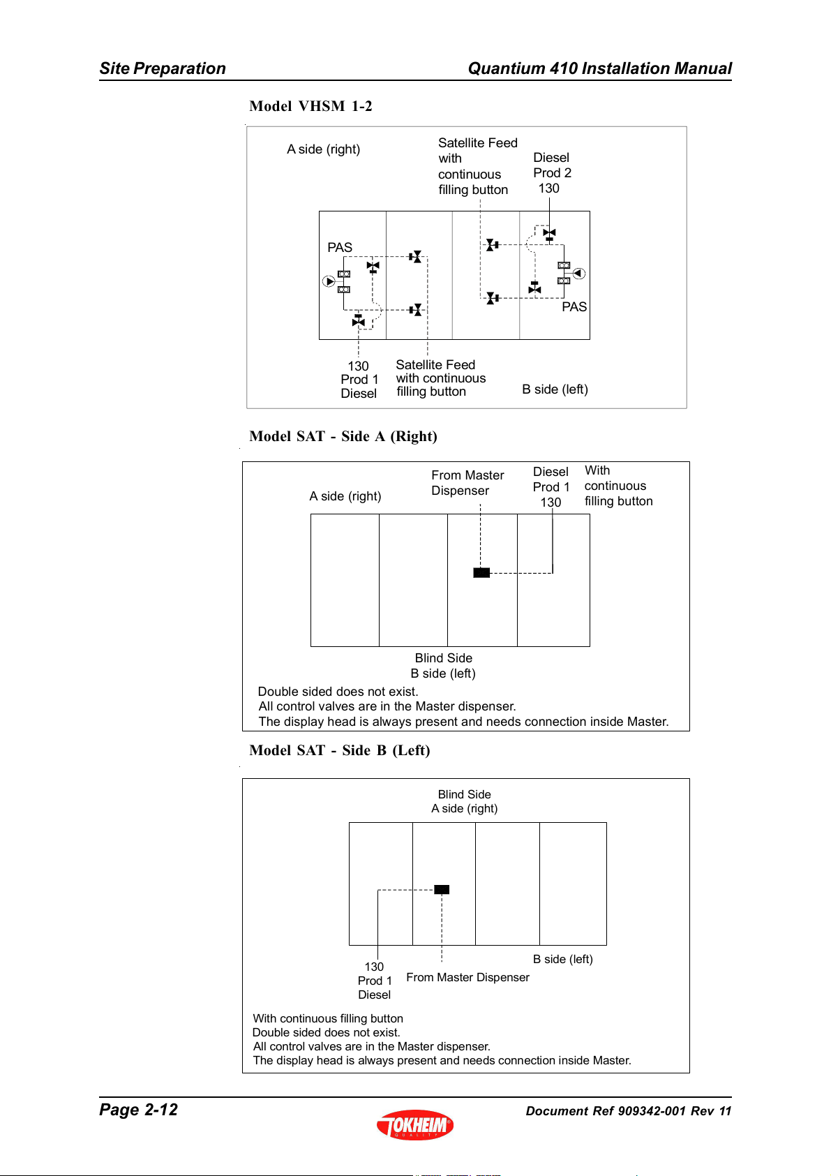
Model VHSM 1-2
A side (right)
PAS
130
Prod 1
Diesel
Satellite Feed
with continuous
filling button
Model SAT - Side A (Right)
A side (right)
Satellite Feed
with
continuous
filling button
From Master
Dispenser
Diesel
Prod 2
130
PAS
B side (left)
Diesel
Prod 1
130
With
continuous
filling button
Blind Side
B side (left)
Double sided does not exist.
All control valves are in the Master dispenser.
The display head is always present and needs connection inside Master.
Model SAT - Side B (Left)
Blind Side
A side (right)
130
Prod 1
Diesel
With continuous filling button
Double sided does not exist.
All control valves are in the Master dispenser.
The display head is always present and needs connection inside Master.
From Master Dispenser
B side (left)
Page 2-12 Document Ref 909342-001 Rev 11
Page 27
Quantium 410 Installation Manual Site Preparation
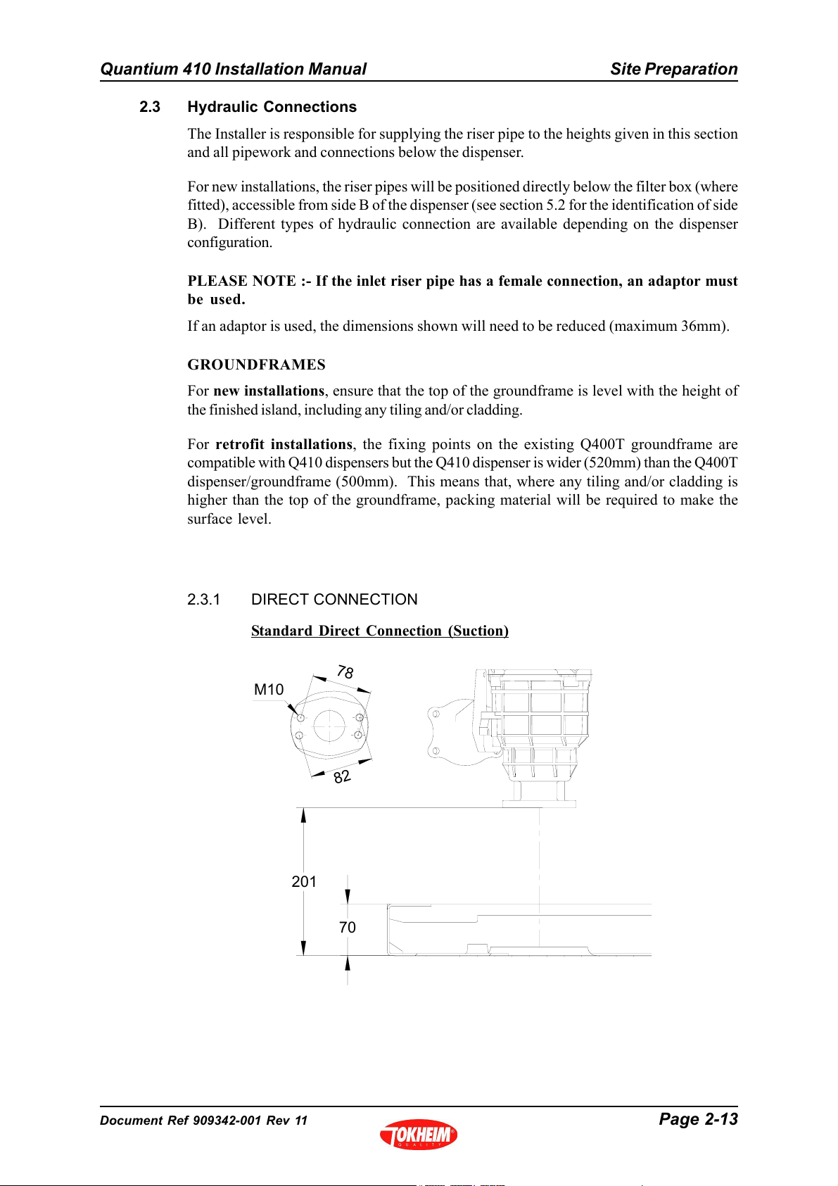
2.3 Hydraulic Connections
The Installer is responsible for supplying the riser pipe to the heights given in this section
and all pipework and connections below the dispenser.
For new installations, the riser pipes will be positioned directly below the filter box (where
fitted), accessible from side B of the dispenser (see section 5.2 for the identification of side
B). Different types of hydraulic connection are available depending on the dispenser
configuration.
PLEASE NOTE :- If the inlet riser pipe has a female connection, an adaptor must
be used.
If an adaptor is used, the dimensions shown will need to be reduced (maximum 36mm).
GROUNDFRAMES
For new installations, ensure that the top of the groundframe is level with the height of
the finished island, including any tiling and/or cladding.
For retrofit installations, the fixing points on the existing Q400T groundframe are
compatible with Q410 dispensers but the Q410 dispenser is wider (520mm) than the Q400T
dispenser/groundframe (500mm). This means that, where any tiling and/or cladding is
higher than the top of the groundframe, packing material will be required to make the
surface level.
2.3.1 DIRECT CONNECTION
Standard Direct Connection (Suction)
7
8
M10
2
8
201
70
Document Ref 909342-001 Rev 11 Page 2-13
Page 28
Site Preparation Quantium 410 Installation Manual
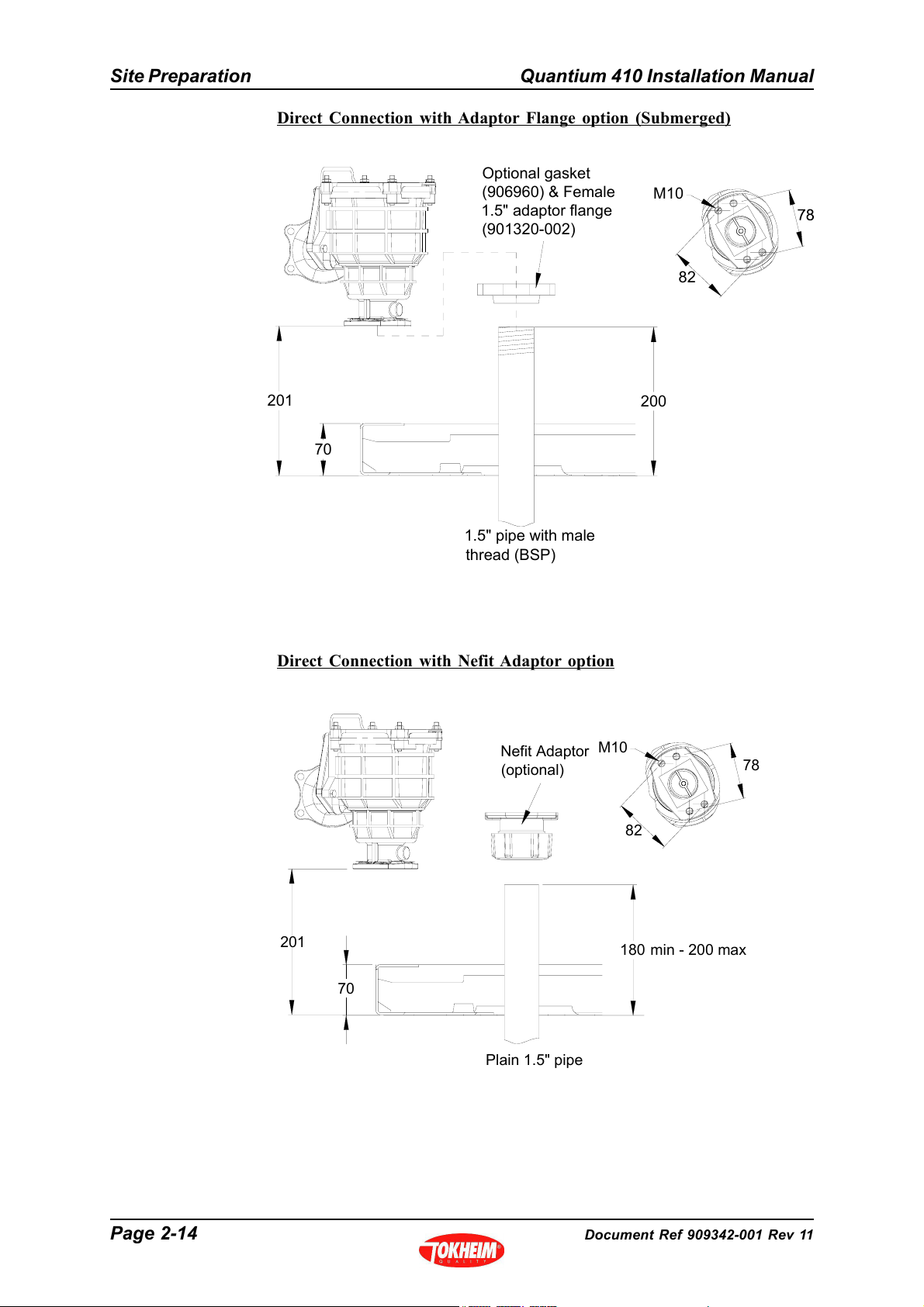
Direct Connection with Adaptor Flange option (Submerged)
Optional gasket
(906960) & Female
1.5" adaptor flange
(901320-002)
M10
82
201
70
1.5" pipe with male
thread (BSP)
Direct Connection with Nefit Adaptor option
Nefit Adaptor
(optional)
200
M10
78
82
201
70
Plain 1.5" pipe
min - 200 max
180
Page 2-14 Document Ref 909342-001 Rev 11
Page 29

Quantium 410 Installation Manual Site Preparation
Direct connection with Nefit Adaptor & Tokheim Shear Valve option
Nefit Adaptor
(optional)
Pipe 903583
(optional)
201
70
2.3.2 FLEXIBLE CONNECTION (SUCTION ONLY)
Recommended Riser Heights
1.5" male
thread on flexi
70
90
50
Tokheim Shear Valve
901108 (optional)
1.5" female
thread on flexi
5090
1.5" Pipe with
female thread
(incl. plastic pipes)
Note :
The rubber cover (manchet) for the driptray must be lower than the pipe joints
(& thread adaptors)
Document Ref 909342-001 Rev 11 Page 2-15
1.5" Pipe with
male thread
2" Pipe with
male thread
2" Pipe
with female thread
Page 30
Site Preparation Quantium 410 Installation Manual
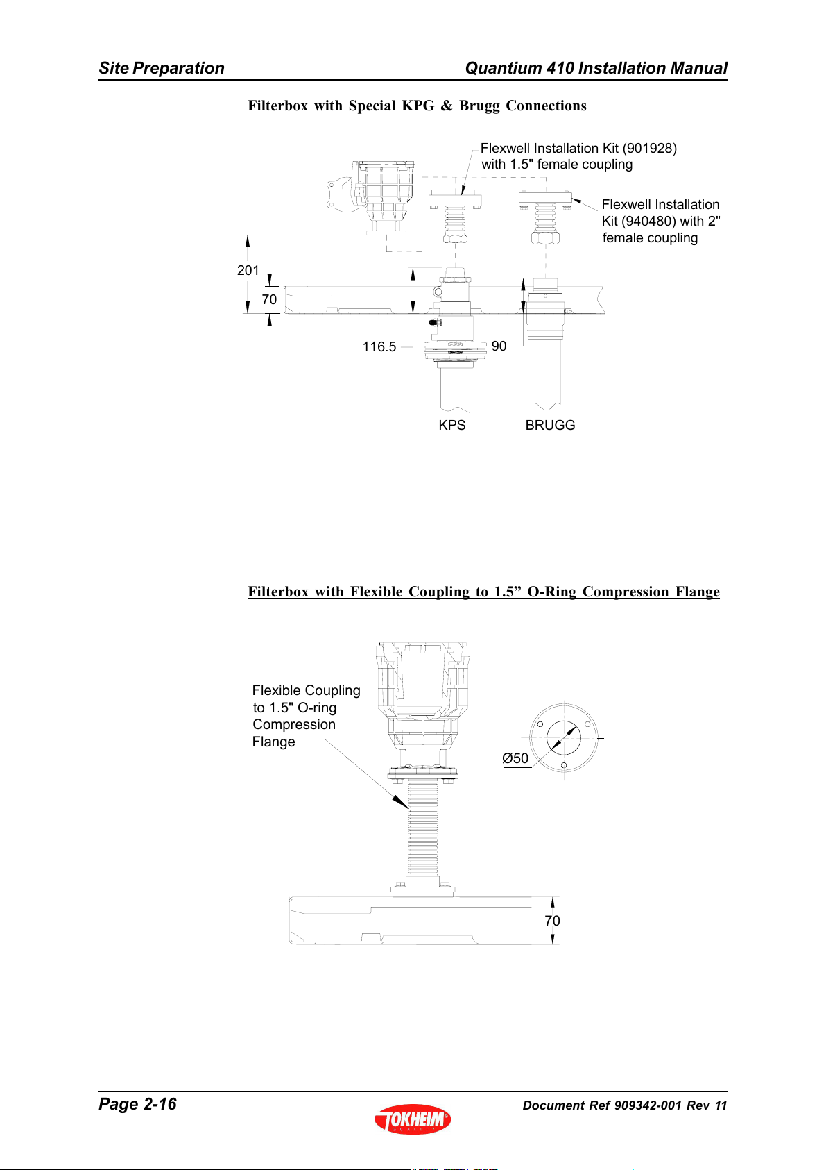
Filterbox with Special KPG & Brugg Connections
Flexwell Installation Kit (901928)
with 1.5" female coupling
Flexwell Installation
Kit (940480) with 2"
female coupling
201
70
116.5
KPS
90
BRUGG
Filterbox with Flexible Coupling to 1.5” O-Ring Compression Flange
Flexible Coupling
to 1.5" O-ring
Compression
Flange
Ø50
70
Page 2-16 Document Ref 909342-001 Rev 11
Page 31

Quantium 410 Installation Manual Site Preparation
Filterbox with Flexible Coupling to 1.5” Female Thread
Rc 1.5"
Flexible
Coupling to
1.5" Female
Thread
90
70
EPZ Internal Filter & Flexible Coupling
Flexi kit 906637 available
containing:-
Flexible tube 380mm x 1.5",
Flange,O-ring & screws
Adaptor
903466-001
required for 2" pipe
70
50
M6 (2x)
90
2" pipe with
male thread
214
77
1.5" pipe with
male thread
Document Ref 909342-001 Rev 11 Page 2-17
Page 32

Site Preparation Quantium 410 Installation Manual
2.3.3 MASTER TO SATELLITE CONNECTION
78
Connection
Flange Level
Ø12
203
70
2.3.4 SATELLITE CONNECTION
78
Ø12
Connection
Flange Level
201
Page 2-18 Document Ref 909342-001 Rev 11
Page 33

Quantium 410 Installation Manual Site Preparation
y
2.3.5 VAPOUR RECOVERY CONNECTIONS
Standard VR Connection
For M6 screw
78
Connection
Flange Level
70
Gasket
Flange 1" 78mm
M10 Nut
VR Connection with OPW Shear Valve (Option)
900758-003Insulation Sleeve
901859
901320-001
900011-004
Nipple
901772
Underside of dispenser
Fix to ground frame
Terminate VR pipe
34.5mm below dispenser
VR Riser Pipe with
male threadG1"
900015-022
901596
Fix to driptray
Weak point level with
top of ground frame
56.5
M10x45 Bolt
Flange on Dispenser
VR Flexi
70
IMPORTANT
Assembl
below the shear point
must be secured to the ground
frame (NOT dispenser frame)
Driptray
height
NOTE : All threads must be
sealed using Loctite 577
Document Ref 909342-001 Rev 11 Page 2-19
Page 34

Site Preparation Quantium 410 Installation Manual
y
VR Connection with Risbridger Shear Valve (UK & EIRE) Kit
fixed to
Risbridger Shear Valve
Clamp
ground frame
906069
Driptray
70
height
Underside of dispenser
fixed to
Clamp
securing bracket
VR Riser Pipe with
male threadG1"
NOTE : All threads must be
sealed using Loctite 577
Weak point level with
top of ground frame
97.5
IMPORTANT
Assembl
must be secured to the ground
frame (NOT dispenser frame)
Terminate VR pipe
79.5mm below dispenser
below the shear point
Page 2-20 Document Ref 909342-001 Rev 11
Page 35

Quantium 410 Installation Manual Site Preparation
SPECIAL INFORMATION RELATING TO HIGH BLEND ETHANOL
FUELS (HBEF) & VAPOUR RETURN (VR) RETURN LINES
Following extensive explosion safety tests with HBEF by PTB, Tokheim
recommends all pipework back to the vapour space of the HBEF storage tank
should be protected by special flame arresters.
The vapour return line to the underground storage tank should be protected in
the event of a vehicle collision with a dispenser and also for maintenance operations.
The flame arrester(s) in the dispenser VR pump do not meet this requirement.
An additional flame arrester must be positioned under the dispenser and must be
protected from potential damage during a vehicle collision so it remains connected
to the vapour return line to the tank in the event that the dispenser is knocked off
the island.
Note : This flame arrester is a requirement of the installation, not a requirement
of the dispenser.
If the Stage II VR return lines are routed back to the HBEF tank then the VR
return line from the dispenser vapour recovery system should protect the tank by
including a flame arrester.
The correct type of flame arrester must be carefully selected:-
• Deflagration or detonation arrester dependent upon its position relative to the
anticipated end of line
• Inline type (unless it can be guaranteed to be at the end of line during maintenance
or after a vehicle collision)
• End of line types will need to be suitable for use with burning alcohol
• Arrester must be suitable for the correct Gas Group:-
- Ethanol blends 60% to 90% require Gas Group IIA Arresters
- Ethanol blends >90% require Gas Group IIB1 Arresters
• Arrester must be manufactured from materials suitable for use with ethanol and
bio-ethanol blended fuels
Tokheim offer two kits for use with Quantium dispensers to fullfil these
requirements, both kits using the inline deflagration flame arrester certified for
use with Gas Group IIB1 thus suitable for all percentage ethanol blends. The kit
must be installed in close proximity to the underside of the dispenser in accordance
with the drawings in this section.
• The standard kit includes an intentionally weak section above the arrester to
ensure that the device remains on the underground vapour pipe following a vehicle
collision
• The alternative kit includes a certified shear valve (with poppets) above the
arrester which additionally ensures that the line back to the tank is closed following
a vehicle collision
Document Ref 909342-001 Rev 11 Page 2-21
Page 36

Site Preparation Quantium 410 Installation Manual
g
VR Connection with Shear Point & Flame Arrester for Ethanol
Kit 1 - Tokheim Part No 943143-001
Insulation Sleeve
Gasket
Flange 1" 78mm
M10 Nut
Nipple
Shear Valve
3
G1"- G
" Nipple
4
(Under Clamp)
Flame Arrester
U Clamp
VR Riser Pipe with
male threadG1"
NOTE : All threads must be
sealed using Loctite 577
900758-003
901859
901320-001
900011-004
901772
904587
900416
943050-001
903184
900015-022
901596
M10x45 Bolt
e on Dispenser
Flan
VR Flexi
Driptray
70
U Clamp
height
903184
Underside of dispenser
70
86
Terminate VR Pipe
70mm below dispenser
IMPORTANT
Assembly below the shear point
must be secured to the ground
frame (NOT dispenser frame)
Page 2-22 Document Ref 909342-001 Rev 11
Page 37

Quantium 410 Installation Manual Site Preparation
VR Connection with Risbridger Shear Valve & Flame Arrester for Ethanol
Kit 2 - Tokheim Part No 943143-002
Gasket
Flange 1" 78mm
M10 Nut
Nipple
U Clamp
3
G1"- G
" Nipple
4
(Under Clamp)
Flame Arrester
900758-003Insulation Sleeve
901859
901320-001
900011-004
901772
903184
900416
943050-001
VR Riser Pipe with
male threadG1"
900015-022
901596
U Clamp 903184
fixed to ground frame
Underside of dispenser
169.5
Terminate VR pipe
154mm below dispenser
M10x45 Bolt
Flange on Dispenser
VR Flexi
Driptray
70
height
NOTE : All threads must be
sealed using Loctite 577
2.4 Electrical Connections
The electrical connection to be established between the kiosk and the dispenser exists in
different configurations. The mains connection (power from the mains supply panel to the
dispenser) and the data connection (link between forecourt controller and calculator) are
customer, country and configuration specific. The number of cores and the cross section
of the cable will be specified, as will the cable construction (armoured or Explosion proof)
and guidance troughs, channels or cable trunks have to be carried out in accordance with
national technical regulations.
IMPORTANT
Assembly below the shear point
must be secured to the ground
frame (NOT dispenser frame)
Document Ref 909342-001 Rev 11 Page 2-23
Page 38

Site Preparation Quantium 410 Installation Manual
2.5 Submerged Connections
Submerged Connection only (with Filterbox, without Flexible coupling)
Island Level
Submerged Connection with Shear Valve (Filterbox only)
NEFIT NUT
Pipe 951639
165
Driptray
70
height
Shear Valve 901108
117
38
Page 2-24 Document Ref 909342-001 Rev 11
G1.5"
Page 39

Quantium 410 Installation Manual Drawings
CONTENTS
3 DRAWINGS ................................................................................................................... 3-2
3.1 Dispenser Dimensions. .........................................................................................3-2
3.1.1 Standard Head (To August 2011) ........................................................3-2
3.1.2 TQC -VGA Media Head (From September 2011) ..............................3-3
3.1.3 Q410 LC - Standard Head .................................................................. 3-4
3.2 GroundFrames ...................................................................................................... 3-5
3.2.1 Retrofit Groundframe .......................................................................... 3-5
3.2.2 Direct Connection Groundframe ......................................................... 3-5
3.2.3 Groundframe Part Numbers ................................................................3-6
3.3 Ground Plan - New Installations only................................................................... 3-6
3.3.1 Generic DripTray .................................................................................3-6
3.3.2 Single Product ......................................................................................3-7
3.3.3 Two Product ........................................................................................3-8
3.3.4 Three Product ...................................................................................... 3-9
3.3.5 Four Product ......................................................................................3-10
3.3.6 Master................................................................................................ 3-11
3.3.7 Satellite .............................................................................................. 3-12
Document Ref 909342-001 Rev 11 Page 3-1
Page 40

Drawings Quantium 410 Installation Manual
3 DRAWINGS
3.1 Dispenser Dimensions.
3.1.1 STANDARD HEAD (TO AUGUST 2011)
152
370
2389
24820
620
1454
210 =380=
1250
1640
960
1200 to 5 key
Centre of Handle
520
Page 3-2 Document Ref 909342-001 Rev 11
Page 41

Quantium 410 Installation Manual Drawings
3.1.2 TQC -VGA MEDIA HEAD (FROM SEPTEMBER 2011)
2389
1556
=489=
620
152
505
370
24820
1777
210 =380=
1250
960
1200 to 5 key
Centre of Handle
520
Document Ref 909342-001 Rev 11 Page 3-3
Page 42

Drawings Quantium 410 Installation Manual
3.1.3 Q410 LC - STANDARD HEAD
Page 3-4 Document Ref 909342-001 Rev 11
Page 43

Quantium 410 Installation Manual Drawings
3.2 GroundFrames
3.2.1 RETROFIT GROUNDFRAME
907448-001 Retrofit
1004
510
1260
Hole group 1: Retrofit Ground plan
1
97
3.2.2 DIRECT CONNECTION GROUNDFRAME
907448-002 Direct Connection
1004
386
VR
510
386
1260
97
VR
Hole group 2: Direct Connection Ground plan
Document Ref 909342-001 Rev 11 Page 3-5
2
Page 44

Drawings Quantium 410 Installation Manual
3.2.3 GROUNDFRAME PART NUMBERS
M ODEL CON FIGU RATION GROU N D FRAM E PART N UM BER COM M EN TS
All Models Suction 907448-002 Without transversal bracket
All Models Submerged 907448-002 With transversal bracket to block rigid pipe
All Models Suction 946553 For BRUGG risers
All Models Suction 946554 For KPS riser
All Models Suction 946555 For KPS riser (Designed for Italy)
3.3 Ground Plan - New Installations only
3.3.1 GENERIC DRIPTRAY
Side A (Right)
Mounting
Holes (x4)
67
SAT B
520
386
All dimensions
given from extent
of driptray
P1
or P2
1250
1004
SAT A
or P3
P4
812
581
VR
350
123
EL
141.5
186.5
Base
118
285
150
1043
Side B (Left)
Page 3-6 Document Ref 909342-001 Rev 11
Page 45

Quantium 410 Installation Manual Drawings
3.3.2 SINGLE PRODUCT
(MODELS 1-2, HS 1-1, HS 1-2, HS 1-4, VHS 1-1, VHS 1-2)
Side A (Right)
MODEL HS 1-1 SIDE A (RIGHT)
EL
P1
VR
Side B (Left)
Side A (Right)
MODEL VHS 1-1 SIDE A (RIGHT)
P1
P1
P1
Side B (Left)
Side A (Right)
Side B (Left)
Side A (Right)
Side B (Left)
P1
VR
VR
VR
EL
EL
EL
MODEL HS 1-1 SIDE B (LEFT)
MODEL VHS 1-1 SIDE B (LEFT)
MODEL 1-2
MODEL HS 1-2
MODEL VHS 1-2
Side A (Right)
MODEL HS 1-4
P1
Side B (Left)
Key
P1 = Product 1
EL = Electrical Supply
VR = VR per dispenser
Document Ref 909342-001 Rev 11 Page 3-7
P1
EL
VR
Page 46

Drawings Quantium 410 Installation Manual
3.3.3 TWO PRODUCT
(MODELS 2-2, 2-4, HS 2-2, HS 2-4, VHS 2-4)
Side A (Right)
P1
P1
P1
Side B (Left)
Side A (Right)
Side B (Left)
Side A (Right)
Side B (Left)
P2
P2
P2
VR
VR
VR
EL
EL
EL
MODEL 2-2 SIDE B (LEFT)
MODEL HS 2-2 SIDE B (LEFT)
MODEL 2-4
MODEL HS 2-4
MODEL 2-2 SIDE A (RIGHT)
MODEL HS 2-2 SIDE A (RIGHT)
Side A (Right)
P1
Side B (Left)
Key
P1 = Product 1
P2 = Product 2
EL = Electrical Supply
VR = VR per dispenser
P1
VR
EL
MODEL VHS 2-4
Page 3-8 Document Ref 909342-001 Rev 11
Page 47

Quantium 410 Installation Manual Drawings
3.3.4 THREE PRODUCT
(MODELS 3-3, 3-6, HS 3-3, HS 3-6)
Side A (Right)
P1
P1
P2
Side B (Left)
Side A (Right)
P2
Side B (Left)
Side A (Right)
P3
P3
VR
VR
EL
EL
MODEL 3-3 SIDE A (RIGHT)
MODEL HS 3-3 SIDE A (RIGHT)
MODEL 3-3 SIDE B (LEFT)
MODEL HS 3-3 SIDE B (LEFT)
P2
P1
Side B (Left)
Key
P1 = Product 1
P2 = Product 2
P3 = Product 3
EL = Electrical Supply
VR = VR per dispenser
P3
VR
EL
MODEL 3-6
MODEL HS 3-6
Document Ref 909342-001 Rev 11 Page 3-9
Page 48

Drawings Quantium 410 Installation Manual
3.3.5 FOUR PRODUCT
(MODELS 4-4, 4-8, HS 4-4, HS 4-8)
Side A (Right)
P1
P1
P1
P2
P2
P2
P3
Side B (Left)
Side A (Right)
P3
Side B (Left)
Side A (Right)
P3
P4
P4
P4
VR
VR
VR
EL
EL
EL
MODEL 4-4 SIDE A (RIGHT)
MODEL HS 4-4 SIDE A (RIGHT)
MODEL 4-4 SIDE B (LEFT)
MODEL HS 4-4 SIDE B (LEFT)
MODEL 4-8
MODEL HS 4-8
Side B (Left)
Key
P1 = Product 1
P2 = Product 2
P3 = Product 3
P4 = Product 4
EL = Electrical Supply
VR = VR per dispenser
Page 3-10 Document Ref 909342-001 Rev 11
Page 49

Quantium 410 Installation Manual Drawings
3.3.6 MASTER
(MODELS HSM 1-1, VHSM 1-1, VHSM 1-2)
TO SAT
Side A (Right)
Side B (Left)
Side A (Right)
SAT
P1
Side A (Right)
B
TO SAT
SAT
A
Side B (Left)
TO SAT
P1
VR
VR
EL
EL
MODEL HSM 1-1 SIDE A (RIGHT)
MODEL VHSM 1-1 SIDE A (RIGHT)
MODEL HSM 1-1 SIDE B (LEFT)
MODEL VHSM 1-1 SIDE B (LEFT)
SAT
P1
Key
P1 = Product 1
EL = Electrical Supply
VR = VR per dispenser
SAT A = Satellite Feed Side A
SAT B = Satellite Feed Side B
SAT
B
TO SAT
A
Side B (Left)
P1
VR
EL
MODEL VHSM 1-2
Document Ref 909342-001 Rev 11 Page 3-11
Page 50

Drawings Quantium 410 Installation Manual
3.3.7 SATELLITE
Side A (Right)
SAT
Side B (Left)
Side A (Right)
SAT
Side B (Left)
Key
EL = Electrical Supply
SAT = Satellite Inlet
VR
VR
EL
EL
MODEL SAT SIDE B (LEFT)
Page 3-12 Document Ref 909342-001 Rev 11
Page 51

Quantium 410 Installation Manual Packaging & Handling
CONTENTS
4 PACKAGING & HANDLING ................................................................................... 4-2
4.1 Shipping Documentation ....................................................................................... 4-2
4.2 Packaging .............................................................................................................4-2
4.2.1 Unpacking ............................................................................................ 4-2
4.3 Inventory Inspection .............................................................................................4-2
4.4 Weights .................................................................................................................4-3
4.5 Handling ............................................................................................................... 4-3
4.6 Access to the Hydraulic Area.............................................................................. 4-4
4.7 Access the Junction Box Connections .................................................................4-4
4.8 Access to the Calculator Head ............................................................................4-5
4.9 Access to the Cable Glands .................................................................................4-5
Document Ref 909342-001 Rev 11 Page 4-1
Page 52

Packaging & Handling Quantium 410 Installation Manual
4 PACKAGING & HANDLING
4.1 Shipping Documentation
The following documents will accompany every delivery:-
• Shipping List
!Packing/Checking List
!CE Sticker
•Certificate of Conformity
The Serial Number on the dispenser should be identical to the Serial Number on the Shipping
List, CE sticker and Certificate of Conformity. Please inform Tokheim UK Ltd before
unpacking if there are any discrepancies in the notation.
4.2 Packaging
The type of packing depends on the destination of the goods. All products containing a
frame are fixed on a pallet by means of screws and by the use of beams or blocks screwed
onto the frame.
The goods are protected from moisture and scratching by bubble wrap and polystyrene
corner blocks and a standard carton is used for packing. Where the use of a forklift truck
or pallet truck is necessary, special arrangements make this possible through the use of
pallets, beams, dispenser beam bridges or blocks.
All separate components belonging to the same delivery are packed together.
4.2.1 UNPACKING
When the dispensers arrive at the installation site, the unpacked units should be
inspected for possible shipping damage. If damage is evident, it must be reported
to the carrier. Shipping damage is not covered under the Tokheim warranty
policy.
After checking the equipment, the dispenser may be unwrapped. Cladding is
packed in such a way that paint, screening and stickers are protected. Take
care when unwrapping so that these elements are not damaged.
After unwrapping, the dispensers must be checked for any faults or damage.
Any faults or damage found must be reported to the Installation Supervisor
immediately.
Make sure that all packing materials are removed from the service station. It is
recommended that you discuss this with the station’s supervisor.
4.3 Inventory Inspection
After unpacking and prior to installation, the delivered equipment should be inspected to
ensure that all the required materials are on hand, and the dispensers have all the ordered
options and markings. If discrepancies in dispenser options and markings are evident,
contact Tokheim UK Ltd.
Page 4-2 Document Ref 909342-001 Rev 11
Page 53

Quantium 410 Installation Manual Packaging & Handling
4.4 Weights
Approximate weight of an 8 hose dispenser : 660kg (maximum configuration).
PLEASE NOTE : THE ABOVE WEIGHTS ARE APPROXIMATE AND WILL
VARY ACCORDING TO OPTIONS FITTED.
4.5 Handling
The recommended procedure for safe handling of the dispenser is by use of a forklift
truck.
The installer must supply all handling equipment and ensure safe working practice at all
times.
Document Ref 909342-001 Rev 11 Page 4-3
Page 54

Packaging & Handling Quantium 410 Installation Manual
4.6 Access to the Hydraulic Area
The following instructions detail the procedure to be followed for the safe removal of the
hydraulic door panel(s).
INSTRUCTIONS
1) Locate the keys for the hydraulic door.
2) Place the nozzle(s) on the ground in a safe position.
3) Simultaneously unlock both keylocks on the hydraulic door and
carefully open the door at the top.
Note : The door is still attached by a retaining lanyard
and earth cable.
4) Disconnect the retaining lanyard and earth cable from the inside
of the hydraulic door.
5) Lift up the door to release from the slots in the driptray and
remove the hydraulic door completely.
6) Place the hydraulic door in a safe position.
7) Repeat for opposite side of dispenser as required.
8) To re-fit the hydraulic door(s), follow the instructions in reverse.
9) Close the dust caps to prevent water or dirt entering the
keylock.
4.7 Access the Junction Box Connections
The following instructions detail the procedure to be followed to allow safe access to the
junction box connections.
INSTRUCTIONS
1) Follow the instructions given in section 4.6 to remove the
hydraulic door panel on side B of the dispenser.
2) Locate the junction box on side B of the dispenser.
3) Using a 6mm allen key, loosen and remove the ten bolts on
the junction box cover on side B of the dispenser. Remove
the junction box cover completely.
4) Refer to the wiring diagrams in section 5.
5) To re-fit the junction box cover, follow the instructions in
reverse.
Page 4-4 Document Ref 909342-001 Rev 11
Page 55

Quantium 410 Installation Manual Packaging & Handling
4.8 Access to the Calculator Head
The following instructions detail the procedure to be followed for the safe access to the
calculator head.
INSTRUCTIONS
1) Locate the keys for the calculator head door.
2) Simultaneously unlock both keylocks on the calculator head
door on the relevant side of the dispenser
Note : Exact position of keylocks may vary according to
the model ordered.
3) Carefully open the calculator head door.
4) Secure the calculator head door in the open position by inserting
the lever into the slot provided.
5) Repeat for opposite side of dispenser as required.
6) To close the calculator head door, follow the instructions in
reverse.
Note : ensure the retaining rope, electrical and/or earth
cables remain inside when closing the calculator head
door.
7) Close the dust caps to prevent water or dirt entering the
keylock.
4.9 Access to the Cable Glands
The following instructions detail the procedure to be followed for the safe removal of the
nozzle panel(s).
INSTRUCTIONS
1) Open the hydraulic door on the relevant side of the dispenser.
2) Carefully lift the relevant nozzle out of the nozzle boot and place in a
safe position on the ground.
WARNING : BEWARE OF FUEL SPILLAGE.
3) Gently prise off the plastic cap cover located in the middle of the
nozzle panel to access the fixing screw.
4) Using a 4mm allen key, loosen and remove the fixing screw in the
middle of the nozzle panel and the two screws and plastic washers
located at the bottom of the nozzle panel.
5) Carefully lift the nozzle panel upwards and away from the dispenser.
Note : The nozzle panel is still attached by the nozzle
switch(es).
Document Ref 909342-001 Rev 11 Page 4-5
Page 56

Packaging & Handling Quantium 410 Installation Manual
6) Using a 7mm spanner and 7mm nut runner, loosen and remove the
nut, screw and two washers to disconnect the nozzle switch from
the nozzle panel.
7) Remove the nozzle panel completely and place in a safe position.
8) To re-fit the nozzle panel, follow instructions in reverse.
Page 4-6 Document Ref 909342-001 Rev 11
Page 57

Quantium 410 Installation Manual Installation
CONTENTS
5 INSTALLATION.......................................................................................................... 5-2
5.1 General .................................................................................................................5-2
5.2 Identification of Sides ...........................................................................................5-2
5.3 Lifting ................................................................................................................... 5-3
5.4 Placement............................................................................................................. 5-3
5.4.1 By Forklift ............................................................................................ 5-4
5.4.2 Q410 LC By Forklift ............................................................................5-5
5.4.3 Leak Plate Sealing ...............................................................................5-7
5.4.4 Fixing to Ground ...................................................................................5-8
5.4.5 Earthing ................................................................................................5-9
5.5 Hydraulic Connections ....................................................................................... 5-10
5.5.1 Installation of TQP-HS Pumps ..........................................................5-10
5.5.2 Pipework - dispensers with direct connection
(Suction or Submerged) ..................................................................... 5-10
5.5.3 Pipework - dispensers with flexible connection
(Suction only) ..................................................................................... 5-11
5.5.4 Fitting a Risbridger Check Valve ....................................................... 5-13
5.5.5 Spin On Filter (Option) ...................................................................... 5-13
5.5.6 Pipework - VR .................................................................................. 5-14
5.5.7 New Submerged Installation ..............................................................5-14
5.6 Electrical Connections ........................................................................................5-16
5.6.1 Junction Box Wiring ........................................................................... 5-16
5.6.2 Communications Wiring in Main Junction Box .................................. 5-25
5.6.3 Special Dispenser Configurations ...................................................... 5-27
5.6.4 Outdoor Payment Terminals and Vidium Power ............................... 5-29
Document Ref 909342-001 Rev 11 Page 5-1
Page 58

Installation Quantium 410 Installation Manual
5 INSTALLATION
5.1 General
Before the dispenser can be installed, the Safety Instructions as described in Section 1.5
and the Installation Instructions in this section must be carefully read.
Follow unpacking instructions in Section 4.2.1.
After unwrapping and before installation, the dispensers must be checked for any faults or
damage. Any faults or damage found must be reported to the Installation Supervisor
immediately.
NOTE: IF USING SUBMERGED PUMPS, THE CONTROL MUST BE
COMPLETELY ISOLATED DURING ALL PHASES OF INSTALLATION.
The following checks need to be made before starting the installation :-
• Check that the electric cabling and the piping arrangements have been made in accordance
with the Installation drawings in section 3.
• Where applicable, check that the leakage plates have been produced in accordance with
the Installation drawing. Any differences or defects should be reported to the Installation
Supervisor immediately. The function of the leakage plate is to drain leakages to the
outside of the dispenser where they act as a warning to the station attendant.
• Check that all flame arresters are correctly installed according to the drawings.
5.2 Identification of Sides
The different sides of the dispenser referred to in this manual are described as follows:-
• Side A of the dispenser has no air vent holes in the drip tray. With the calculator head
opened, side A has the centre plate cover.
Side A
Page 5-2 Document Ref 909342-001 Rev 11
Page 59

Quantium 410 Installation Manual Installation
• Side B of the dispenser has air vent holes in the drip tray at the base of the dispenser. Side
B has the inlet connections and junction box, visible once the front panel is removed. With
the calculator head opened, side B houses the battery and the programming of the calculator.
Side B
Lifting equipment can be
hazardous, and must be
rated to lift the weight of the
dispenser. Equipment
could fall and cause severe
injury or death. Stand clear
Air Vent holes
in drip tray
from the dispenser when
lifting and lowering.
5.3 Lifting
The responsibility for carrying out the procedures described in this manual lies with the
persons lifting and placing the dispenser.
The installer must supply all lifting equipment and ensure safe working practice at all
times.
Q410 dispensers, excluding Q410 LC, can be lifted by forklift truck under the calculator
head or by forklift slots located in the driptray.
IMPORTANT : Q410 LC dispensers should ONLY be lifted using the forklift
slots located in the driptray. Under no circumstances should the dispensers be
lifted under the calculator head.
5.4 Placement
Before placement on the island can take place, the following procedures must be carried
out:-
• Check that the electric cabling and piping arrangements have been made in accordance
with the Installation drawing
• Check the pipes have been flushed before connecting the hydraulic components (if necessary,
contact the tank installer)
• Removal of stop plugs on fuel and vapour recovery pipes
• Preparation of mounting frame
• Fitting of seals for cable, fuel and vapour recovery pipe access
• Sealing of non-used holes
Document Ref 909342-001 Rev 11 Page 5-3
Page 60

Installation Quantium 410 Installation Manual
5.4.1 BY FORKLIFT
Follow the instructions in section 4.6 to access the dispenser hydraulic area.
PREPARE THE DISPENSER FOR
LIFTING
1) Use a 19mm spanner or socket to loosen and
remove the four bolts (one per corner) securing
the dispenser to the pallet/transport profile.
IMPORTANT :
Where supplied, the leak plate must be
placed in the ground PRIOR to positioning
the dispenser. Once placed, the leak plate
must be sealed around the edge of the
leakplate and screw holes using a suitable
sealant.
2) IMPORTANT :
Protect the dispenser paint work under the
calculator head using cardboard or similar
non-abrasive material.
3) Using a block of wood or similar, carefully
lift the dispenser using a forklift truck under
the calculator head.
POSITION THE DISPENSER ON THE
ISLAND
4) Position the dispenser over the island and feed
the cables up through the electrics hole position
in the driptray.
5) Ensure the filter boxes are directly above the fuel
supply risers then carefully lower the dispenser
onto the island.
Note : Do NOT remove the forklift at this point.
6) Align the mounting holes in the dispenser driptray
with the corresponding holes in the ground.
7) Follow the instructions in section 5.4.3 to secure
the dispenser to the ground using the two mounting
holes at the
8) With one side of the dispenser secured, remove
the forklift. Follow the instructions in section 5.4.3
to locate the opposite two bolts into the two
remaining holes provided.
Dispenser placement is complete.
opposite side to the forklift.
Page 5-4 Document Ref 909342-001 Rev 11
Page 61

Quantium 410 Installation Manual Installation
5.4.2 Q410 LC BY FORKLIFT
Follow the instructions in section 4.6 to access the dispenser hydraulic area.
IMPORTANT :
Where supplied, the leak plate must be placed
in the ground PRIOR to positioning the
dispenser. Once placed, the leak plate must
be sealed around the edge of the leakplate and
screw holes using a suitable sealant.
PREPARE THE DISPENSER FOR LIFTING
1) Use a 19 mm spanner or socket to loosen
and remove the two nearside bolts securing
the dispenser to the transport pallet.
2) Position the forks of a suitable forklift to the lifting slots in
the driptray.
Carefully insert the forks, stopping prior to reaching the
two far side securing bolts.
Note : For slot dimensions, please refer to dimension
drawing in Section 3.1.3 Q410 LC
3) Remove the two far side securing bolts.
Insert the forks until they are visible through the far side
of the driptray.
Do not raise the forks.
Protect the dispenser panels with cardboard or other
suitable material, then strap the dispenser to the forklift
using a ratchet strap or similar to ensure stability and
safety.
Document Ref 909342-001 Rev 11 Page 5-5
Page 62

Installation Quantium 410 Installation Manual
4) Raise the dispenser and carefully position it over the cradle so that the filter
boxes are directly above the fuel supply risers. Lower the dispenser slowly,
aligning the mounting holes on the driptray with the mounting holes on the cradle.
5) Follow the instructions in section 5.4.3 to secure
the dispenser to the ground using the two
mounting holes at the
6) With the dispenser now secure, remove the retaining ratchet straps.
Ensure that the area around the dispenser is clear of all personnel, then slowly
remove the forklift and move it away from the dispenser.
opposite side to the forklift.
7) Follow the instructions in section 5.4.3 to secure the dispenser to the ground
using the two remaining mounting holes.
8) Using a rust preventative fluid, such as Waxoyl
professional 120-4 (Black), apply a generous
coating to the inside and outside of the forklift
slots.
9) Fit the supplied blanking plates to all 4 slots in
the driptray and apply a coat of rust
preventative around the 4 edges of each
blanking plate.
Dispenser placement is complete.
Page 5-6 Document Ref 909342-001 Rev 11
Page 63

Quantium 410 Installation Manual Installation
5.4.3 LEAK PLATE SEALING
To fulfill to ECN13617-1, it is required to apply sealant between leak-plate and
island (or alternatively cradle) or between integrated drip-tray and island (or
alternatively cradle) as per instruction hereafter.
Apply suitable fuel resistant sealant on the surface of the leak-plate/integrated
drip-tray, apply suitable fuel resistant sealant around fixing holes on the island as
per below sketch - sealant represented by blue line.
Document Ref 909342-001 Rev 11 Page 5-7
Page 64

Installation Quantium 410 Installation Manual
5.4.4 FIXING TO GROUND
The following information relates to a typical Tokheim dispenser, unmodified by
the user, with no additional advertisement boards, canopies or items added to the
dispenser. Any such modifications may affect the stability and have warranty/
liability consequences.
IMPORTANT:- Tokheim dispensers must be secured to the ground
using all 4 mounting positions provided in the driptray - refer to the
groundplan drawings in section 3 for mounting hole positions.
TYPICAL FIXING INTO CONCRETE (NO GROUNDFRAME)
M12 ANCHOR BOLT FOR
CONCRETE high tensile
WASHER
min thickness = 2mm
min dia = 25mm
Underside of
dispenser driptray
Min depth into
concrete = 100mm
100
TYPICAL FIXING INTO TOKHEIM GROUNDFRAME
WASHER
min thickness 2mm
min dia 25mm
Underside of
dispenser driptray
Tokheim groundframe
M12 BOLT high tensile
Nut insert
TYPICAL FIXING INTO THIRD PARTY GROUNDFRAME / SUMP
FRAME
M12 BOLT high tensile
Alternative to nut & washer :-
Welded nut on groundframe
with min. 5 captured threads
Underside of
dispenser driptray
Steel groundframe/
sump frame
WASHERS
min thickness = 2mm
min dia = 25mm
M12 NUT
Page 5-8 Document Ref 909342-001 Rev 11
Page 65

Quantium 410 Installation Manual Installation
5.4.5 EARTHING
Earthing requirements are dictated by local National regulations and must always
be observed.
Tokheim recommends the following guidelines as a minimum requirement:-
2
• 6mm
• 10mm
earth conductor(s) back to main site earth (up to 85m cable run)
2
earth conductor(s) back to main site earth (85 to 150m cable run)
The primary earth connection point for Quantium dispensers is the M2000T
Junction Box provided for installation cable connections. Threaded inserts or
studs (M8) are also provided in the base frame as alternative or additional earth
connection points.
Earthing requirements are dependent upon the number of earth conductors
provided (one per power cable) and the types of cable used. For example,
where steel wire armour cables or MICC are used in conjunction with the
appropriate termination glands, no supplementary specific earth cable is likely to
be required. Where simple PVC covered cables are used, Tokheim recommends
an additional earth core is connected to the point provided on the dispenser base
frame.
IMPORTANT : It is the responsibility of the Installer to supply the
earth wire and ensure the dispenser is safely earthed.
The photograph below is an typical example of an earth connection point on a
Q410 dispenser :-
Document Ref 909342-001 Rev 11 Page 5-9
Page 66

Installation Quantium 410 Installation Manual
5.5 Hydraulic Connections
Connect all hydraulic and electric junctions according to the specifications as described in
this section and indicated on the drawings in Section 3.
Flow rates achieved are dependent upon the type of submerged pumping system used and
other site-specific conditions.
Connections to the fuel supply pipes and the vapour return lines
are accessible from side B of the dispenser (see section 5.2 for
identification of sides).
The dispenser is positioned with the filter box positioned above
the relevant fuel supply risers. If required, adapters should be
fitted to the supply pipes.
Note : The maximum pressure must not exceed 3.5 bar.
5.5.1 INSTALLATION OF TQP-HS PUMPS
IMPORTANT INFORMATION:
DO NOT INSTALL TQP-HS PUMPS, 80 OR 130 LPM, IN SERIES ON
THE SAME SUCTION LINE.
SEPARATE SUCTION LINES ARE REQUIRED, AS EXAMPLES
SHOW BELOW:
9.6 m³/h
160 l/min
TQP-HS80TQP-HS
80
5.5.2 PIPEWORK - DISPENSERS WITH DIRECT CONNECTION (SUCTION OR SUBMERGED)
The Installer is responsible for supplying the riser pipe to the heights given in
section 2.3 and all pipework and connections below the filter box connection.
EXTERNAL FILTER BOX ONLY (SUCTION PUMPS OR
SUBMERGED)
1) The dispenser must be positioned directly above the
riser pipes and carefully lowered into position.
2) Remove the protective covers on the fuel supply riser
pipe and on the filter box.
WARNING : BEWARE OF FUEL SPILLAGE.
Page 5-10 Document Ref 909342-001 Rev 11
Page 67

Quantium 410 Installation Manual Installation
3) Cut the rubber manchet to suit the riser pipe diameter
and fit over the pipe to cover the hole in the driptray.
4) Connect the fuel supply pipe to the filter box or optional
flange (where fitted).
5) Repeat for each hydraulic position as required.
5.5.3 PIPEWORK - DISPENSERS WITH FLEXIBLE CONNECTION (SUCTION ONLY)
The Installer is responsible for supplying the riser pipe to the heights given in
section 2.3. The flexible connection should then be fitted between the fuel
supply risers and the filter box.
SUCTION PUMPS WITH EXTERNAL FILTER BOX ONLY
1) Remove the protective covers on the fuel supply riser
pipe and on the filter box.
WARNING : BEWARE OF FUEL SPILLAGE.
2) Cut the rubber manchet to suit the riser pipe diameter
and fit over the pipe to cover the hole in the driptray.
3) Apply a sealant compound to the fuel supply riser
and to the inside of the flexible coupling.
4) Fit the flexible coupling to the fuel supply riser pipe.
Note : Hand tighten only at this point
5) Insert the top hat filter (provided in the installation
kit) into the flexible coupling.
6) Manoeuvre the flexible coupling into the correct
position, ready for securing to the filter box.
Document Ref 909342-001 Rev 11 Page 5-11
Page 68

Installation Quantium 410 Installation Manual
7) Insert the gasket between the filter box and the flange
on the flexible coupling.
8) Fit the flange to the filter box using the two screws
provided in the installation kit.
Note : Hand tighten only at this point.
9) Use a large adjustable spanner to tighten and secure
the flexible connection to the fuel supply riser pipe.
10) Using a 15mm spanner or socket, tighten the two
screws on the flange.
11) Repeat steps 1 to 10 for each hydraulic position as
required.
TQP-RS PUMPS WITH INTERNAL FILTER ONLY
1) If the riser pipe is not 1.5” diameter male thread then an adaptor will need to be
fitted by the Installer.
2) Fit the female end of the flexible connection to the male thread on the fuel
supply pipe in the ground and tighten using a large adjustable spanner.
3) Where fitted, remove the hygiene cover on the inlet
connection on the pump.
4) Using a 13mm spanner, fit the two bolts on the flange
to secure the flexible connection to the pump.
5) Repeat steps 1 to 4 for each hydraulic position.
Page 5-12 Document Ref 909342-001 Rev 11
Page 69

Quantium 410 Installation Manual Installation
5.5.4 FITTING A RISBRIDGER CHECK VALVE
If a Risbridger Check Valve has to be fitted to a dispenser :
• remove the check valve - for pumps with internal filters
• remove the foot valve - for pumps with external filters
Risbridger
Check Valve
Remove
Foot Valve
EXTERNAL
FILTER
Remove
Check Valve
INTERNAL
FILTER
5.5.5 SPIN ON FILTER (OPTION)
The installer is responsible for ensuring the following procedures are carried out
correctly, using the recommended Wix 24027 filter.
1) Within the hydraulics section, locate the spin on filter
housing and ensure all valves are in the closed position.
(Horizontal)
2) Remove the filter from its packaging and apply a film
of oil around the gasket.
3) Carefully place it in the housing and begin to tighten by
hand until the gasket has made contact. Apply another 3/4
of a turn.
Note : Do not over tighten the filter.
Document Ref 909342-001 Rev 11 Page 5-13
Page 70

Installation Quantium 410 Installation Manual
4) When the filter is firmly in place, turn the ball valve to
the open position. (Vertical). The procedure is now
complete.
Note : Ensure that the line is subsequently bled
to release any air in the sytem.
5.5.6 PIPEWORK - VR
The Installer is responsible for supplying the VR pipe to the heights given in
section 2.3.
1) Fit the VR flange and gasket to the VR pipe.
2) As required, fit optional flame arrestor, quick connector and/or shear valve kits
to the VR pipe flange, sealing with gaskets, o-rings, dowty seals and washers as
supplied.
3) Ensure that the VR flexi pipes are not put under strain, trapped or twisted then
connect VR flexi pipe to the VR pipe.
5.5.7 NEW SUBMERGED INSTALLATION
Depending on the dispenser an additional plate at the end of the hydraulic cabinet
to balance the dispenser during installation may be required. This is fitted in
production on specific configurations only, it is left in place once the dispenser is
installed.
Description of Parts
Submerged
Filter
Assembly
Nefit Nut
Nefit Pipe
Driptray
Shear
Valve
Page 5-14 Document Ref 909342-001 Rev 11
Page 71

Quantium 410 Installation Manual Installation
WARNING : BELOW INSTALLATION PROCEDURE MUST BE
STRICTLY FOLLOWED WITH THE NEW SUBMERGED.
1) Ensure that the nefit pipe is fully inserted inside the filter pot.
2) Lower the dispenser until it sits on the
groundframe.
Note: no risk that the nefit pipes will collide
with the shear valves as it is inserted deep
enough inside the filter pots
3) Untighten the Nefit nut.
4) Slide down the Nefit pipe.
5) Screw the Nefit pipe into the Shear valve.
6) Tighten the Nefit nut.
Document Ref 909342-001 Rev 11 Page 5-15
Page 72

Installation Quantium 410 Installation Manual
5.6 Electrical Connections
During installation, the main switch must be switched off - ensure the main switch cannot
be switched on inadvertently.
The installation of the cables must be carried out carefully to ensure the Eex-norm is
enforced (insertion of cables via glands).
The electrical connections are compatible with all European installation practices and typical
country specific cable types. The following information is the Tokheim recommended
installation, however where differences exist in the standards relating to installation according
to country specific legislation, the local/national standards must be employed.
CABLING
The type of cabling used will differ by country according to local and/or national laws and
regulations. The drawings in this section show the minimum number of cores required in
cables and the minimum core cross sectional area. Cables with more than the minimum
can be used provided that the cables are suitable for use with the cable gland sizes fitted.
Individual cables can be combined provided that the minimum number of conductors remains.
The maximum number of forecourt cables required will be :-
• One power cable for motor power supply
• One power cable for calculator supply
• One/two cable(s) for dispenser communications
• One cable for speaker (optional)
• One ethernet CAT5 cable per side for OPT communications (optional)
• One cable per submerged pump control signals (where applicable)
ELECTRONICS AND LIGHTING PROTECTION
Tokheim recommends a 2-pole thermal-magnetic device for protection of the metering
pump electronics. A fuse must NOT be used in the neutral conductor. Thermal-magnetic
Breakers or fuses must be capable of extinguishing a fault current of at least 4000A.
Note : Provision for lighting supply is not required as LED backlighting is standard.
MOTOR WIRING
The number of motors per dispenser will vary according to different models and options.
Always connect to the furthest left terminal first. Jumper sizes and positions will vary
according to the number of motors.
5.6.1 JUNCTION BOX WIRING
During the removal or replacement of the M2000 Junction Box cover, the
machined flame path of the cover and the junction box should be inspected for
damage. If any defects or scratches are found then the junction box and/or
cover must be replaced - this is essential for product safety. Once removed,
always store the cover in a safe place.
Note : The correct tightening torque for the junction box cover is 18Nm.
Page 5-16 Document Ref 909342-001 Rev 11
Page 73

Quantium 410 Installation Manual Installation
Three different sizes of cable gland entries are available from Tokheim for the
M2000T Junction Box:-
• For cable sizes 6-11mm
• For cables sizes 10-13mm
• For cable sizes 14-17mm
Ensure that the correct gland size is chosen to suit each installation cable. Failure
to do so will compromise product safety.
The special requirements relating to the use of the M2000T Junction box are:-
• Gland size 6-11mm must be tightened to a torque of 114Nm
• Gland size 10-13mm must be tightened to a torque of 35Nm
• Gland size 14-17mm must be tightened to a torque of 70Nm
• Ensure that all cables terminating in the M2000T Junction Box are securely
fastened to the dispenser frame adjacent to the box.
The wiring in the main junction box will vary according to different models and
options. The drawings in this section show the Tokheim recommended installation
but differences may exist in the standards relating to installation in different
countries and local regions, in which case the local and/or national standards
must be employed.
Document Ref 909342-001 Rev 11 Page 5-17
Page 74

Installation Quantium 410 Installation Manual
Three Phase Suction
TERMINALS INSIDE MAIN
JUNCTION BOX
Motor Wiring
The number of motors varies.
Always connect to the furthest left
terminal i.e. furthest left L1, furthest
left L2, furthest left L3. Jumper sizes
and positions vary for different
amounts of motors.
PE
MOTORS
CALC
L4 L5
LIGHT/HEATER
Note 1 : Motor, Electronics &
Lighting Protection
Tokheim recommends the use of a
3 P+N Lockable Type 'D' MCB.
10 amp for 40/80 MPD dispensers
or single product 130 litre/min
dispensers.
16 amp for MPD 130 litre/min
dispensers.
FORECOURT WIRING
KIOSK EQUIPMENT
Note 2 :
WWC 2A
TQC 6A
TQC-VGA 6A
L1 L1 L1 L2 L2 L2 L3 L3 L3
MOTOR POWER
(4x1.5mm² cable)
* Note 1
MOTOR
MCB
CALC POWER
(3x1.5mm² cable)
* Note 2
CALC
MCB
N N
L4 L5
LIGHT/HEATER
POWER
(3x1.5mm² cable)
* Note 3
LIGHT/
HEATER
MCB
Note 3 :
LIGHT 8A
HEATER 8A
Note : The Lighting Supply cable is only required for models with the option
Illuminated Product Indication (IPI). Dispenser models with standard LED
backlighting only do not require this installation cable.
Page 5-18 Document Ref 909342-001 Rev 11
Page 75

Quantium 410 Installation Manual Installation
Single Phase Suction
TERMINALS INSIDE MAIN
JUNCTION BOX
CALC
Motor Wiring
The number of motors varies. Always
connect to the furthest left terminal i.e.
furthest left L1. Jumper sizes and
positions vary for different amounts of
motors.
PE
MOTORS
LIGHT/HEATER
L4 L5
Note 1 : Motor, Electronics &
Lighting Protection
Tokheim recommends the use of
a 2 P Lockable Type 'D' MCB.
16 amp for all single product
dispensers and 2 product 40/80
dispensers.
20 amp for all other MPD (single
product implies one riser position).
FORECOURT WIRING
KIOSK EQUIPMENT
Single Phase Alternative
Calculator & Lighting may share a
common supply cable and link L4 to
L5, N4 to N5.
Note 2 :
WWC 2A
TQC 6A
TQC-VGA 6A
L1 L1 L1 L1 N N N N
MOTOR POWER
(3x2.5mm² cable)
* Note 1
MOTOR
MCB
* Note 2
CALC
CALC POWER
(3x1.5mm² cable)
MCB
N N
L4 L5
941939-002 Rev 2
LIGHT/HEATER
POWER
(3x1.5mm² cable)
* Note 3
LIGHT/
HEATER
MCB
Note 3 :
LIGHT 8A
HEATER 8A
Document Ref 909342-001 Rev 11 Page 5-19
Page 76

Installation Quantium 410 Installation Manual
Three Phase Suction Alternative
TERMINALS INSIDE
Note 1 : Motor, Electronics & Lighting
Protection
Tokheim recommends the use of a 3
P+N, Lockable Type 'D' MCB.
6 amp for submerged pumps.
10 amp for 40/80 MPD pumps or single
product 130l/min pumps.
16 amp for MPD 130l/min pumps.
Installation with a 5 core MICC cable is
possible by linking L3 to L4 and L5
within the dispenser mains box.
MAIN JUNCTION BOX
PE
L1 L1 L1 L2 L2 L2 L3 L3 L3
MOTORS
CALC
L4 L5
N N
L4 L5
LIGHTS/HEATER
FORECOURT WIRING
KIOSK EQUIPMENT
Note 2 :
WWC 2A
TQC 6A
TQC-VGA 6A
Note 3 :
LIGHT 8A
HEATER 8A
MOTOR, CALCULATOR &
LIGHT/HEATER POWER
(7x1.5mm² cable)
L1 L2 L3 L4 L5 N PE
*Note 2
*Note 3
* NOTE 1
MCB
Page 5-20 Document Ref 909342-001 Rev 11
Page 77

Quantium 410 Installation Manual Installation
Submerged
TERMINALS INSIDE
Motor Wiring
The number of motors varies.
Always connect to the furthest left
terminal i.e. furthest left L1, furthest
left L2, furthest left L3 etc. Jumper
sizes and positions vary for different
amounts of motors.
Motor, Electronics & Lighting
Protection
Tokheim recommends the use of
a 3 P+N Lockable Type 'D' MCB.
10 amp for 40/80 MPD
dispensers or single product 130
litre/min dispensers.
16 amp for MPD 130 litre/min
dispensers.
MAIN JUNCTION BOX
PE
MOTORS
L1 L1 L2 L2 L3 L3
CALC
L4 L5
N N
L4 L5
LIGHT/HEATER
SUB
4 5 6
1 2 3
Key:-
1 = SUB 1
2 = SUB 2
3 = SUB 3
4 = SUB 4
5 = SUB 5
6 = COMM
4 5 6
4 5 6 1 2 3
FORECOURT WIRING
KIOSK EQUIPMENT
Note 1 :
WWC 2A
TQC 6A
TQC-VGA 6A
Note 2 :
LIGHT 8A
HEATER 8A
(4x1.5mm² cable)
6A
MOTOR
MCB
VR MOTOR
POWER
(3x1.5mm² cable)
* Note 1
CALC
MCB
CALC POWER
* Note 2
LIGHT/
HEATER
LIGHT/HEATER
(3x1.5mm² cable)
MCB
POWER
CONTROL SIGNAL
(7x0.75mm² cable)
SUB PUMP
941939-003 Rev 2
Document Ref 909342-001 Rev 11 Page 5-21
Page 78

Installation Quantium 410 Installation Manual
Master for Satellite
Key:-
1 = RN01
2 = RBU1
3 = VBU
4 = LN01
5 = LBU1
6 = VBU
4 5 6
SHIELD 1 2 3 4 5 6 7 8
1 2 3 4 5 6 7 8
TERMINALS INSIDE MAIN
JUNCTION BOX IN
MASTER DISPENSER
FORECOURT WIRING
NOZZLE - LEFT &
BUTTON
(4x1.5mm² PVC cable)
1 2 3
4 5 6
1 2 3
DISPLAY - LEFT
(8x0.75mm² PVC cable)
TO SATELLITE LEFT
1 2 3 4 5 6 7 8
1 2 3 4 5 6 7 8
SHIELD 1 2 3 4 5 6 7 8
NOZZLE - RIGHT &
BUTTON
(4x1.5mm² PVC cable)
TO SATELLITE RIGHT
DISPLAY - RIGHT
(8x0.75mm² PVC cable)
941939-004 Rev 1
Page 5-22 Document Ref 909342-001 Rev 11
Page 79

Quantium 410 Installation Manual Installation
Satellite
1 2 3 4 5 6 7 8
1 2 3 4 5 6 7 8
TERMINALS INSIDE
MAIN JUNCTION
BOX IN SATELLITE
FORECOURT WIRING
KIOSK EQUIPMENT
1 2 3 4 5 6 7 8
SHIELD 1 2 3 4 5 6 7 8
1 2 3
NOZZLE & BUTTON
(4x1.5mm² PVC cable)
Key:-
1 = N01
2 = BU1
3 = VBU
DISPLAY
(8x0.5mm² PVC cable)
941939-006 Rev 2
Document Ref 909342-001 Rev 11 Page 5-23
Page 80

Installation Quantium 410 Installation Manual
Fire & Tilt Detection (in additional Junction Box)
TERMINALS INSIDE ADDITIONAL
BERNSTEIN JUNCTION BOX
FORECOURT WIRING
KIOSK EQUIPMENT
Shock/
Tilt
Detection
Fire
Detection
(1)
1 2 3 4 5 6 7 8
SHIELD
Tilt Detection and/or
Fire Detection
Fire
Detection
(2)
(6x0.5mm²)
1 - Tilt Detector 1
2 - Tilt Detector 2
3 - -
4 - (1st) Fire Detector 1
5 - (1st) Fire Detector 2
6 - -
7 - (2nd) Fire Detector 1
8 - (2nd) Fire Detector 2
902675-016 Rev 1
Audio Option (in additional Junction Box)
TERMINALS INSIDE ADDITIONAL
BERNSTEIN JUNCTION BOX
FORECOURT WIRING
1 2 3 4 5 6 7 8
L-AUDIO +
L-AUDIO -
R-AUDIO +
R-AUDIO -
SHIELD
AUDIO INPUT
(4x0.5mm²
shielded/pyro cable)
KIOSK EQUIPMENT
902675-015 Rev 1
Page 5-24 Document Ref 909342-001 Rev 11
Page 81

Quantium 410 Installation Manual Installation
5.6.2 COMMUNICATIONS WIRING IN MAIN JUNCTION BOX
Communications wiring in the main junction box will vary according to the different
communication protocols.
UP TO FOUR TERMINAL COMMS
LEFT
Post Oct 2006
(up to 4 terminals)
5
1234
567
Installation cable
KIENZLE
5 6 7 8
1 2 3 4
XL
XR
YL
YR
6
screen
7
8
8
RIGHT
Pre-Oct 2006
(up to 4 terminals)
1234 5678
Installation cable
TOK
5 6 7 8
1 2 3 4
(in)
GND
TTD
TTC (out)
screen
IMPORTANT
cut as close as possible to cable
glands
Ensure wiring in dispenser
matches wiring in kiosk
EIN
5 6 7 8
1 2 3 4
TX
GND
GND
RX
screen
82D
5 6 7 8
1 2 3 4
GND
not used
not used
RX+TX
screen
4 core
screened cable
AUTOTANK
5 6 7 8
1 2 3 4
OH
4 core
screened cable
OL
IH
screened cable
IL
screen
screened cable
3 core
DRESSER
4 core
5 6 7 8
1 2 3 4
LR-
LT-
LR+
4 core
screened cable
LT+
screen
LEFT
4 core
screened cable
ZSR
5 6 7 8
1 2 3 4
R-
L-
L+
2 core
screened cable
5 6 7 8
1 2 3 4
R+
screen
RIGHT
2 core
screened cable
M32
SCREEN
screen
Document Ref 909342-001 Rev 11 Page 5-25
Page 82

Installation Quantium 410 Installation Manual
METAX
5 6 7 8
1 2 3 4
2 core
screened cable
EIGHT TERMINAL COMMS
(8 terminals)
5
6 7 8
2 3
4
1
RT-
RT+
Pre-Oct 2006
(8 terminals)
3
21 645 78
DUN
5 6 7 8
1 2 3 4
L-
2 core MICC
cable
LON
5 6 7 8
1 2 3 4
L+
R+
R-
tail
seal
earth
bare
tinned
screen
copper
copper
2 core MICC
cable
IMPORTANT
Screen and unused wires must be cut as
close as possible to cable glands
2 core LON
cable
outer
screen
5
7
6
8
Installation cable
EPS/
TATSUNO
5 6 7 8
1 2 3 4
LT+
LT-
LR+
LR-
RT-
RR-
RT+
RR+
screen
screen
Installation cable
in kiosk
LOG
5 6 7 8
1 2 3 4
TTC
GND
TTD
24V
Aut/Man
Low Lev L
Prod Pos
Low Lev R
screen
NUOVO
PIGNONE
5 6 7 8
1 2 3 4
TxB-1
TxA-1
RxA-1
RxB-1
RxB-2
TxA-2
RxA-2
TxB-2
screen
4 core
screened cable
4 core
screened cable
8 core
screened cable
8 core
screened cable
900140 Rev 12
Page 5-26 Document Ref 909342-001 Rev 11
Page 83

Quantium 410 Installation Manual Installation
EPSI INTERFACE
EPSI INTERFACE
5 6 7 8
X2
X2 = Connection Strip
1 2 3 4
mounted in Junction Box
mains.
TB
TA
RA
RB
Coding signals on X2
are calculator signals.
screen
screen
screen
GND
screen
8 core
screened cable
5.6.3 SPECIAL DISPENSER CONFIGURATIONS
With certain combinations of options, additional junction boxes may be required.
Additional
Junction Box 1
1 2 3 4 5 6 7 8
***Comms***
Mains Section
Additional
Junction Box 2
1 2 3 4 5 6 7 8
Junction Box Bracket
***Comms***
Identification Stickers
Usual Comms location
Usual DIT Comms location
Main Junction Box
(M2000/M2000T)
Document Ref 909342-001 Rev 11 Page 5-27
Comms
Section
Page 84

Installation Quantium 410 Installation Manual
• Audio option - if the dispenser is fitted with speakers then the audio connections
are always housed in Junction Box 1.
• Shock Detection option - if the dispenser is fitted with shock detection then the
unit is housed in the Comms section of the Main Junction Box and the dispenser
communications are housed as follows:-
Option Combination Main Junction Box
Fire/Tilt Detection, non-EPS
Comms & DIT
Fire/Tilt Detection, EPS
Comms & DIT
Fire/Tilt Detection, EPS
Comms, DIT & Audio
Fire/Tilt Detection, non-
EPS Comms & DIT
Fire/Tilt Detection &
EPS Comms
Fire/Tilt Detection &
EPS Comms
• High Speed Single Phase Motors - if the dispenser is fitted with high speed
single phase motors then the motor capacitors are housed in the Comms section
of the Main Junction Box and the dispenser communications are housed as
follows:-
Option Combination Main Junction Box
High Speed 1ph motor Motor Capacitors
High Speed 1ph motor & DIT Motor Capacitors
High Speed 1ph motor &
Audio
High Speed 1ph motor, DIT
& Audio
Motor Capacitors Audio
Not an option Not an option Not an option
Additional
Junction Box 1
None None
DIT Comms None
Audio DIT Comms
Additional
Junction Box 1
Dispenser
Comms
Dispenser
Comms
Addi tional
Junction Box 2
Addi ti ona l
Junction Box 2
DIT Comms
Dispenser
None
Comms
Page 5-28 Document Ref 909342-001 Rev 11
Page 85

Quantium 410 Installation Manual Installation
5.6.4 OUTDOOR PAYMENT TERMINALS AND VIDIUM POWER
Note : A separate power cable must be supplied from the kiosk to the dispenser
for Vidium equipped models.
TERMINALS INSIDE MAIN
(3 phase shown)
CALC
L4 L5
VIDIUM
Motor Wiring
The number of motors varies. Always
connect to the furthest left terminal i.e.
furthest left L1, furthest left L2, furthest left
L3. Jumper sizes and positions vary for
different amounts of motors.
JUNCTION BOX
PE
MOTORS
Motor, Electronics & Lighting Protection
*
Tokheim recommends the use of a 3 P+N
Lockable Type 'D' MCB.
10 amp for 40/80 MPD dispensers or single
product 130 litre/min dispensers.
16 amp for MPD 130 litre/min dispensers.
FORECOURT WIRING
KIOSK EQUIPMENT
L1 L1 L1 L2 L2 L2 L3 L3 L3
MOTOR POWER
(4x1.5mm² cable)
*
MOTOR
MCB
CALC / DIT
CALC POWER
(3x1.5mm² cable)
6A
MCB
N N
L4 L5
VIDIUM POWER
(3x1.5mm² cable)
6A
VIDIUM
MCB
Document Ref 909342-001 Rev 11 Page 5-29
Page 86

Installation Quantium 410 Installation Manual
OPT Power Supply 230V connection
To OPT power supply
Loop wires 1,2,3 and 4 through Ferrite.
( Not for Crypto VGA )
5x1.5mm
1
2
3
4
green / yellow
bk15=black 1x1.5mm
bk15-4-T1 black
bk15-5-T1 black
2
5x1.5mm
2 x 230VAC
from mains box
1
3
4
green/yellow
Page 5-30 Document Ref 909342-001 Rev 11
Page 87

Quantium 410 Installation Manual Installation
230V OPT with Fire Detection
BU15=Blue 1x1.5mm
To O PT po w er s u p p l y
Capillary
Thermostat
Loop wires 1,2,3 and 4
through Ferrite.
BU15-1 blue
brown
blue
green/yellow
To filter 230Vac for
transformer WWC
power
5x1.5mm
4
2
1
3
3x1.5mm
green / yellow
FIRE DETECTION STANDARD
1
2
green/yellow
green/yellow
7x1.5mm
3
5
1
2
W664
black
6
4
2
1
4
3
5x1.5mm
green/yellow
2x230Vac
from mains box
Document Ref 909342-001 Rev 11 Page 5-31
Page 88

Installation Quantium 410 Installation Manual
Vidium Audio Button
Vidium Button
Vidium Button
Side A
white
brown
Terminals 2 x 2 way
on option rail
Side B
white
brown
Vidium and Payment
Fuse F5 6, 3A for Vidium
Fuse F4 1, 6A WWC
Rail Assy
942762
W1229 black
brown
blue
green/yellow
230Vac power Vidium
side A
brown
blue
green/yellow
W1164 black
230Vac power Vidium
side B
Page 5-32 Document Ref 909342-001 Rev 11
Page 89

Quantium 410 Installation Manual Installation
Vidium, Fire detection, Payment and OPT Lamp
OPT Lamp
brown
blue
green/yellow
Fuse F5 6,3A for OPT Lamps
and Vidium
Fuse F4 1,6A WWC
Rail Assy
942761
green/yellow
2
1
3
2 x 230VAC
from Mains Box
5 x 1.5mm
W1171 black
W1228 black
4
brown
blue
green/yellow
230Vac power Vidium
Side A
brown
blue
green/yellow
230Vac power Vidium
Side B
Document Ref 909342-001 Rev 11 Page 5-33
Page 90

Installation Quantium 410 Installation Manual
Vidium and Heater
Heater
brown
blue
green/yellow
Fuse F6 6,3A Heater
Fuse F5 6,3A Vidium
Fuse F4 1,6A WWC
2
5 x 1.5mm
W1208 black
Rail Assy
942760
W1178 black
green/yellow
3
1
4
brown
blue
green/yellow
230Vac power Vidium
Side A
brown
blue
green/yellow
230Vac power Vidium
2 x 230VAC from
Side B
Mains Box
Page 5-34 Document Ref 909342-001 Rev 11
Page 91

Quantium 410 Installation Manual Installation
This page is intentionally blank
Document Ref 909342-001 Rev 11 Page 5-35
Page 92

Quantium 410 Installation Manual Commissioning
CONTENTS
6 COMMISSIONING ...................................................................................................... 6-2
6.1 Testing and programming the Dispenser ............................................................ 6-2
6.1.1 Programming the Dispenser ............................................................... 6-2
6.1.2 Dispenser Functions ........................................................................... 6-2
6.1.3 Testing the Dispenser ......................................................................... 6-3
6.2 Calibration of the Dispenser ............................................................................... 6-3
6.2.1 Mechanical Calibration of the Meter ................................................. 6-4
6.2.2 Electronic Calibration of the MPE Pulser .......................................... 6-5
6.2.3 Temperature Compensation Function ................................................ 6-7
6.3 Final Checks ....................................................................................................... 6-8
6.4 Handing over to the Station Manager ................................................................. 6-8
Document Ref 909342-001 Rev 11 Page 6-1
Page 93

Commissioning Quantium 410 Installation Manual
6 COMMISSIONING
The procedures in this section are Tokheim recommended procedures for commissioning the
dispenser but differences may exist in the standards relating to commissioning in different countries
and local regions, in which case the local and/or national standards must be employed.
Follow the instructions given in section 4.8 to gain access to the calculator head.
6.1 Testing and programming the Dispenser
Prior to Commissioning, the following must be checked:-
• Ensure that all the cabling and hydraulic connections have been made correctly.
• Check that power is present.
Note : Disconnect the Comms before switching on power to the dispenser. This will
reduce the possibility of errors.
• Check that the voltage of power supply is in accordance with the WWC calculator voltage.
• Check that back-up batteries are in correct working order.
6.1.1 PROGRAMMING THE DISPENSER
Refer to separate WWC T1 User Manual for more detailed information.
• If permitted, use the User Access Keypad (UAK) to place the dispenser(s) in
Stand-alone Mode and enter the unit prices.
• Alternatively, use the UAK to place the dispenser in Self-Service Mode. Re-
program the console for the new dispenser. The unit prices will be communicated
automatically to the dispenser.
• Check the unit prices are correct for each new dispenser.
• Where applicable, note the readings on the electronic and mechanical totalisers.
6.1.2 DISPENSER FUNCTIONS
• Where fitted, check that the leakage plates are correctly installed.
• Carry out a test filling using each nozzle and check all supported functions are
working correctly (local preset, HS/LS, etc.).
• Check that the nozzles correspond to the correct products and that product names
are correct.
• Check the correct operation of all hose retraction systems.
• Check the correct operation of all locks.
• Check the calculator lighting (where applicable).
• Check that all required warning stickers are in the correct positions.
Page 6-2 Document Ref 909342-001 Rev 11
Page 94

Quantium 410 Installation Manual Commissioning
6.1.3 TESTING THE DISPENSER
The following procedures must be performed at each nozzle position:-
• Test the flow rates (litres/minute) - refer to the WWC Calculator Manual for
more detailed information.
Note : Flow rates will vary depending on site conditions, and should be
adjusted accordingly using the pump bypass.
For VR nozzles, set the flow rate between 36 and 40 LPM.
• Test the meters are within the legal requirements:-
- Lift each nozzle and deliver approximately 20 litres into a Tokheim
approved calibrated container until all air and fuel substitute has been expelled
through the nozzle and/or air vent pipes.
Note : Discard this filling since it will contain fuel substitute from the
dispenser pipes and components and air from the supply pipes.
IMPORTANT : DISCARD ALL TEST FILLINGS SAFELY.
• Perform a test filling into the calibrated container until 20 litres have been
dispensed according to the calculator display.
• Read the measurement on the calibrated container.
If the fuel dispensed into the container is above or below the calibration line
(i.e. greater or less than the 20 litres dispensed) then the meter must be adjusted
to ensure Weights & Measures (W&M) compliance.
Note : W&M regulations vary according to different countries.
6.2 Calibration of the Dispenser
If the meter is fitted with an enhanced pulser for electronic calibration (MPE-EC) or
temperature compensation (MPE-TC) then it should not be necessary to perform mechanical
calibration. Refer to section 6.2.2 to perform electronic calibration.
MID CERTIFIED DISPENSERS
MID certified dispensers are calibrated in the factory with the relevant seals stamped so it
can be put into operation immediately upon installation without Weights & Measures
verification. Refer to section 1.7 for the identification of MID dispensers.
If requested by the site owner, a calibration check could be performed as part of the
commissioning procedure.
If the calibration is outwith legal tolerances, the factory MID verification would be
invalidated. The meter should be adjusted by the commissioning engineer (under factory
approval) before the dispenser becomes operational.
Document Ref 909342-001 Rev 11 Page 6-3
Page 95

Commissioning Quantium 410 Installation Manual
6.2.1 MECHANICAL CALIBRATION OF THE METER
• Carefully remove the W&M seal on the meter.
• Use a TX30 bit to remove the hexalobular screw on
the plastic protective cover on the meter.
• Use a 10mm spanner to calibrate the piston meter by
turning BOTH adjustment screws.
Note : If the error is greater than 0.05% then balance the error by adjusting
both screws equally.
• Adjust in a clockwise direction to reduce the amount of fuel delivered i.e. if the
fuel in the container is greater than the reading on the calculator display.
• Adjust in an anti-clockwise direction to increase the amount of fuel delivered
i.e. if the fuel in the container is less than the reading on the calculator display.
Note : each “click” per adjustment screw corresponds to approximately
0.05% or 10ml.
• Re-test the dispenser until calibration is within acceptable tolerance levels.
• Replace the W&M seals to the adjusted meter.
Page 6-4 Document Ref 909342-001 Rev 11
Page 96

Quantium 410 Installation Manual Commissioning
6.2.2 ELECTRONIC CALIBRATION OF THE MPE PULSER
Refer to separate MPE Pulser Manual for more detailed information. Each
MPE pulser is required to be set up and configured independently.
IMPORTANT - To perform EC, the EC function must be turned ON and
the TC function must be switched OFF.
Connect the User Access Keypad (UAK) to the relevant Dipnet connection on
the Pulser Sealing Board and power up the UAK.
INITIAL SET UP
UAM f o r WWC
Ver s ion: 0107
0750. 00 +20. 3oC
00 00 00 0000
MPE 0 1 . 0 7 D3 3 F
1:MA 2:TST 3:SIM
1:EC 2:SET
3 : SERV 4 : ADC
PARAMETERS
Se t d i r ec t ion
PARAMETERS
Se t EC
The first screen is displayed for a few seconds.
Check the software version is 01.07 or higher.
The UAK checks for connected devices then
alternately flashes between two delivery messages
(displaying raw volume, EC volume, TC volume and
density, temperatue, hose expansion time, value,
suppressed and flow rate).
Press ON to start configuration. A choice of menus
is displayed. Press 1 to enter MAINTENANCE
menu.
Press 2 to enter SET menu to allow entry of the EC/
TC parameters.
The first parameter, DIRECTION, will set the
direction of the rotation for the meters. This is preset
in the factory. Press 7 to skip to next function.
The next parameter, EC, will turn the EC function
on or off. Press F4 to enter EC sub menu.
Se t EC
OF F
PARAMETERS
Se t TC
Se t TC OF F
Default OFF is displayed. Press 7 to change to ON.
Press F4 to save and continue.
The next parameter, TC, will turn the TC function
on or off. Press F4 to enter TC sub menu.
Default OFF is displayed. Press F4 to save and
continue. IMPORTANT : TC must be OFF if EC
is to be performed.
1 : EC 2 : SET
3 : SERV 4 : ADC
Document Ref 909342-001 Rev 11 Page 6-5
Press F1 to return to MAINTENANCE menu.
Page 97

Commissioning Quantium 410 Installation Manual
TEST FILLING PROCEDURE
• Do a test filling at maximum flow rate into a W&M calibrated container.
•Stop the delivery manually when the exact nominal volume of the can is
displayed on the calculator display.
• Check the volume on the gauge on the calibrated container.
• If the difference between the container volume and the calculator display does
not exceed the maximum allowed deviation (check local requirements) then no
further action is necessary. If the difference is outwith the maximum allowed
deviation then follow the instructions below to perform electronic calibration.
ELECTRONIC CALIBRATION FUNCTION
Perform a test filling as described above.
MPE 0 1 . 0 7 D3 3 F
1:MA 2:TST 3:SIM
1:EC 2 : SET
3 : SERV 4 : ADC
Di sp layed vo lume
----.-- L
Can vo l ume
----.-- L
CAL I BRAT I ON OK
CAL I BRAT I ON ERR
NO CHANGE
Press ON to start configuration. A choice of menus
will be displayed. Press 1 to enter MAINTENANCE
menu.
Press 1 to enter EC menu.
Read the volume displayed on the calculator and
enter into the UAK using the numeric keys. Press
F4 to save and continue.
Read the volume displayed on the calibrated
container and enter into the UAK using the numeric
keys. Press F4 to save and continue.
If the difference is within acceptable limits i.e. +/-
0.5% then a new calibration factor will be calculated
and stored and CALIBRATION OK is displayed.
If the difference is outwith the acceptable limit then
CALIBRATION ERR is displayed. Manual
calibration of the meter should then be performed
before attempting electronic calibratation again.
1 : EC 2 : SET
3 : SERV 4 : ADC
Press F1 to return to MAINTENANCE menu.
Page 6-6 Document Ref 909342-001 Rev 11
Page 98

Quantium 410 Installation Manual Commissioning
6.2.3 TEMPERATURE COMPENSATION FUNCTION
Refer to separate MPE Pulser Manual for more detailed information. To set the
temperature compensation (TC) function:-
MPE 0 1 . 0 7 D3 3 F
1:MA 2:TST 3:SIM
1:EC 2:SET
3 : SERV 4 : ADC
PARAMETERS
Se t d i rec t ion
PARAMETERS
Se t EC
PARAMETERS
Se t TC
Se t TC OFF
Press ON to start configuration.
A choice of menus will be displayed.
Press 1 to enter MAINTENANCE menu.
Press 2 to enter SET UP menu.
The first parameter, DIRECTION, is displayed.
Press 7 to skip to next function.
The next parameter, EC, is displayed. Press 7 to
skip to next function.
The next parameter, TC, is displayed. Press F4 to
enter TC sub menu.
Default OFF is displayed. Press 7 to change to ON.
IMPORTANT : TC must be OFF if EC is to be
performed.
Se t TC ON
Se t TC ON
Fuel : 90
Se t TC ON
Densi ty: ----.-
TC Setting OK
En ter (F4)
MPE 0 1 . 0 7 D3 3 F
1:MA 2:TST 3:SIM
UAM f o r WWC
Ver s ion: 0107
Press F4 to save and continue.
Press 7 to scroll through fuel density options:-
3
90 = unleaded 90 (750kg/m
)
95 = unleaded 95 (750kg/m3)
98 = unleaded 98 (755kg/m3)
D iesel = diesel (833kg/m3)
LPG = LPG (537kg/m3)
Or enter density value for different fuel type using
the numeric keys. Press F4 to save and continue.
Press F4 to continue.
Press F1 several times until the main menu is
displayed.
Press OFF to disable the UAK and allow it to be
disconnected safely.
Document Ref 909342-001 Rev 11 Page 6-7
Page 99

Commissioning Quantium 410 Installation Manual
6.3 Final Checks
• Check that all W&M requirements have been fulfilled.
• Where applicable, use the UAK to check the limit of the High Speed Diesel as per W&M
regulations.
• Where applicable, note the readings on the electronic and mechanical totalisers.
• Where applicable, clear the error counters.
• Note the type/serial number(s) of the dispenser(s).
• Complete the Arrival Quality checklists and country specific product identification forms
for the dispensers and return them to the local Sales & Service Division.
6.4 Handing over to the Station Manager
Explain to the Station Manager the working of the dispenser(s) and train him in their use
(according to the User Manual).
Together with the Station Manager, go through the Acceptation checklist to check that
everything has been delivered as ordered and is in good condition. Both the Service
Engineer/Technician and Station Manager must sign the checklist.
The Station Manager must check the unit prices.
Hand over the following documents to the Station Manager:-
• One copy of the installation report including the totals of all totalisers and the type and
serial numbers of dispenser(s).
• User Manual.
• Declaration of Conformity (usually located in the Calculator Head).
• Copy of signed Acceptation checklist (usually located in the Calculator Head).
• All keys.
Page 6-8 Document Ref 909342-001 Rev 11
Page 100

Quantium 410 Installation Manual Commissioning
This page is intentionally blank
Document Ref 909342-001 Rev 11 Page 6-9
 Loading...