

Page 1

Quantium
110 & 210
Installation Manual
Document Ref 947571-001
Rev - 2
03/2011
Page 2

Quantium 110 & 210 Installation Manual
Great care has been taken in the preparation of this manual however T okheim
shall not be liable for any misunderstanding, errors and/or loss or defect
arising from the use of this manual.
Tokheim shall not be liable for damage to the product, nor for personal or
third party injury, caused by incorrect use of the product or by attempts to
maintain or to repair the product by parties other than those fully trained by
Tokheim or by its accredited third party representatives.
Please contact your nearest service department, at the relevant address printed
on the back cover of this manual, should any aspect of this manual be unclear.
© Copyright by T okheim. All intellectual rights arising fr om, accruing to,and
residing in this manual belong to Tokheim. No part of this document may be
repr oduced in any form without the expr ess written permission of Tokheim.
Tokheim reserves the right to apply changes to this document and the
equipment without further notice.
Document Ref 947571-001 Rev 2
Page 3

Quantium 110 & 210 Installation Manual Revision Record
REVISION RECORD
Date Revision Pa ge Rea son
30/06/ 2010 1 All Original Is s ue
03/03/2011 2 3-2 Dimension c han ge
2 3-3 Remove Q110 dimensions drawi ng (di m s from cl adding)
2 3-6 Remove Q210 dimensions drawi ng (di m s from cl adding)
Document Ref 947571-001 Rev 2 1
Page 4

Revision Record Quantium 110 & 210 Installation Manual
This page is intentionally blank
2 Document Ref 947571-001 Rev 2
Page 5

Quantium 110 & 210 Installation Manual Contents
CONTENTS
1 INTRODUCTION......................................................................................................... 1-2
1.1 How To Use This Manual ................................................................................... 1-2
1.2 Product Scope ..................................................................................................... 1-2
1.3 Authorised Technicians....................................................................................... 1-3
1.4 Contact Information ............................................................................................ 1-3
1.5 Health & Safety .................................................................................................. 1-3
1.5.1 Safety Checklist.................................................................................. 1-3
1.5.2 Duties of the Employees..................................................................... 1-3
1.5.3 Hazards ............................................................................................... 1-4
1.5.4 Warning Signs .................................................................................... 1-5
1.5.5 Personal Protective Equipment (PPE) ................................................ 1-6
1.6 Standards & Certificates ..................................................................................... 1-7
1.6.1 Dispenser Marking for the ATEX Directive....................................... 1-7
1.6.2 Special Conditions for Safe Use......................................................... 1-8
1.7 MID Dispensers .................................................................................................. 1-8
2 SITE PREPARATION.................................................................................................. 2-2
2.1 General................................................................................................................ 2-2
2.1.1 Zoning Diagrams ................................................................................ 2-2
2.2 Q110 and Q210 Hose and Pump Configurations................................................ 2-5
2.3 Hydraulic Connections ....................................................................................... 2-7
2.3.1 TQP Connections ............................................................................... 2-7
2.3.2 PAS V3 Connections .......................................................................... 2-8
2.3.3 Submerged Connections ....................................................................2-11
2.3.4 Q210 SDS Connections .................................................................... 2-12
2.3.5 Vapour Recovery Connections ......................................................... 2-12
2.4 Electrical Connections ...................................................................................... 2-16
3 DRAWINGS................................................................................................................... 3-2
3.1 Q110 Dispenser................................................................................................... 3-2
3.1.1 Q110 Dispenser Dimensions .............................................................. 3-2
3.1.2 Q110 Ground Plans ............................................................................ 3-3
3.1.3 Q110 Retention Tray Assembly.......................................................... 3-4
3.1.4 Q110 Ground Fixing........................................................................... 3-4
3.2 Q210 Dispenser................................................................................................... 3-5
3.2.1 Q210 Dispenser Dimensions .............................................................. 3-5
3.2.2 Q210 Ground Plans ............................................................................ 3-6
3.2.3 Q210 Retention Tray Assembly ......................................................... 3-7
3.2.4 Q210 Ground Fixing .......................................................................... 3-7
3.3 Q210 SDS Dispenser .......................................................................................... 3-8
3.3.1 Q210 SDS Dimensions ....................................................................... 3-8
3.3.2 Q210 SDS Ground Plan ..................................................................... 3-9
4 PACKAGING & HANDLING..................................................................................... 4-2
4.1 Shipping Documentation .................................................................................... 4-2
4.2 Packaging ............................................................................................................ 4-2
4.2.1 Unpacking .......................................................................................... 4-2
4.3 Inventory Inspection ........................................................................................... 4-2
4.3.1 Checking List ..................................................................................... 4-3
(CONT.)
Document Ref 947571-001 Rev 2 3
Page 6

Contents Quantium 110 & 210 Installation Manual
4 PACKAGING & HANDLING/
4.4 Dispenser Weights .............................................................................................. 4-3
4.4.1 Q110 Dispenser Weights .................................................................... 4-3
4.4.2 Q210 Dispenser Weights .................................................................... 4-3
4.5 Handling.............................................................................................................. 4-3
4.6 Access the Hydraulic Area.................................................................................. 4-4
4.7 Access the Calculator Head ................................................................................ 4-4
4.8 Access the Junction Box ..................................................................................... 4-5
4.8.1 Bernstein Junction Box ...................................................................... 4-5
5 INSTALLATION........................................................................................................... 5-2
5.1 General................................................................................................................ 5-2
5.2 Identification of Side A....................................................................................... 5-2
5.3 Lifting ................................................................................................................. 5-3
5.4 Placement............................................................................................................ 5-3
5.4.1 By Forklift .......................................................................................... 5-4
5.4.2 Fixing to Ground ................................................................................ 5-6
5.4.3 Earthing .............................................................................................. 5-7
5.5 Hydraulic Connections ....................................................................................... 5-8
5.5.1 Pipework - Suction Dispensers with Internal Filter ........................... 5-8
5.5.2 Pipework - Suction Dispensers with External Filter ........................ 5-10
5.5.3 Pipework - Submerged Dispensers................................................... 5-12
5.6 Electrical Connections ...................................................................................... 5-12
5.6.1 Direct wiring into Terminal Rail - WWC......................................... 5-13
5.6.2 Junction Box Wiring......................................................................... 5-16
5.6.3 Communications Wiring (WWC Head only) ................................... 5-19
5.6.4 OPT Communications option ........................................................... 5-24
6 COMMISSIONING ...................................................................................................... 6-2
6.1 Test and programming the Dispenser ................................................................. 6-2
6.1.1 Program the Dispenser ....................................................................... 6-2
6.1.2 Dispenser Functions ........................................................................... 6-2
6.1.3 Test the Dispenser .............................................................................. 6-2
6.2 Calibration of the Dispenser ............................................................................... 6-3
6.2.1 Mechanical Calibration of the Meter ................................................. 6-3
6.2.2 Electronic Calibration of the MPE Pulser .......................................... 6-4
6.2.3 Temperature Compensation Function ................................................ 6-6
6.3 Final Checks ....................................................................................................... 6-7
6.4 Handing over to the Station Manager ................................................................. 6-7
4 Document Ref 947571-001 Rev 2
Page 7

Quantium 110 & 210 Installation Manual Introduction
CONTENTS
1 INTRODUCTION......................................................................................................... 1-2
1.1 How To Use This Manual ................................................................................... 1-2
1.2 Product Scope ..................................................................................................... 1-2
1.3 Authorised Technicians....................................................................................... 1-3
1.4 Contact Information ............................................................................................ 1-3
1.5 Health & Safety .................................................................................................. 1-3
1.5.1 Safety Checklist.................................................................................. 1-3
1.5.2 Duties of the Employees..................................................................... 1-3
1.5.3 Hazards ............................................................................................... 1-4
1.5.4 Warning Signs .................................................................................... 1-5
1.5.5 Personal Protective Equipment (PPE) ................................................ 1-6
1.6 Standards & Certificates ..................................................................................... 1-7
1.6.1 Dispenser Marking for the ATEX Directive....................................... 1-7
1.6.2 Special Conditions for Safe Use......................................................... 1-8
1.7 MID Dispensers .................................................................................................. 1-8
Document Ref 947571-001 Rev 2 Page 1-1
Page 8

Introduction Quantium 110 & 210 Installation Manual
1 INTRODUCTION
1.1 How To Use This Manual
It is recommended that all relevant persons familiarise themselves with the contents of
this manual prior to carrying out any operations or procedures.
This manual is divided into sections which are described as follows: -
Section 1 - Introduction
This section contains information on how to use the manual, the scope of equipment
covered, recommendations on qualified technicians and contact information. It also
includes relevant health and safety information required for the safe installation and
commissioning of the product.
Section 2 - Site Preparation
This section details the procedures to be carried out in preparation for receipt of equipment
at site and the necessary actions prior to installation.
Section 3 - Drawings
All necessary drawings required for reference during the installation and commissioning,
are listed and contained in this section.
Section 4 - Packaging and Handling
This section provides instructions for unpacking and safe handling of the equipment.
Section 5 - Installation
The instructions for the correct installation of the equipment are contained within this
section.
Section 6 - Commissioning
This section highlights the actions and checks, to be carried out, in preparation for the
commissioning activity and the procedures required from commissioning of the equipment
to handover.
1.2 Product Scope
The equipment and models covered by the contents of this manual are: -
The Quantium 110 & 210 range of fuel dispensers, with the exception of the LPG versions.
For information on Quantium LPG dispensers refer to the relevant LPG manual as provided
by T okheim.
All dispensers in the Quantium 110 & 210 ranges use the same standard sub-assemblies
and offer a wide range of configurations and includes provision for options such as vapour
recovery etc.
Page 1-2 Document Ref 947571-001 Rev 2
Page 9

Quantium 110 & 210 Installation Manual Introduction
1.3 Authorised T echnicians
Only qualified technicians familiar with the contents of this manual should carry out the
procedures contained herein.
WARNING : ANY ATTEMPTS TO CARRY OUT THE PROCEDURES OF THIS
MANUAL, BY UNQUALIFIED OR UNAUTHORISED PERSONS, MAY RESULT
IN SERIOUS INJURY OR LOSS OF LIFE.
NOTE : THIS MANUAL IS NOT INTENDED TO REPLACE THE SERVICES OF
A FULLY QUALIFIED TECHNICIAN.
1.4 Contact Information
For information relating to the contents of this manual please contact: T echnical Author
Tokheim UK Ltd.
Dundee, Scotland
author@dundee.tokheim.com
For technical assistance please contact the appropriate service division listed on the back
cover of this manual.
1.5 Health & Safety
1.5.1 SAFETY CHECKLIST
•It is obligatory that this checklist be fully complied with during all work at the
petrol station, particularly construction or repair work.
•It is the duty of the contractor to ensure that all workers employed by him obey
each and all of the relevant laws, directives and other regulations.
Areas where special caution is required
•The insides of tanks, tubes, dome shafts, filling shafts, change over shafts, vessels
and dispensers.
•All areas in which fuel vapour that is heavier than air can accumulate, e.g. fuel
separator, draining shafts, low located rooms, cellars, excavations, pipe trenches
etc.
•The areas around the outlets of tank ventilation pipes, especially during the
filling phase.
•All areas near dispensers, tanker lorries and other vehicles while they are being
tanked up, and particularly when there is a lack of wind.
•A radius of 1.0 metres around petrol carrying pipes, as well as pipes that are not
vapour free.
•Silt traps.
1.5.2 DUTIES OF THE EMPLOYEES
•To ensure optimal accident prevention in our company, in addition to general
rules applying to worker’s protection, it is necessary to take into account all the
national protection of workers legislation and to actively support all measures
which enhance safety standards.
Document Ref 947571-001 Rev 2 Page 1-3
Page 10

Introduction Quantium 110 & 210 Installation Manual
•It is an employee’s duty to follow all company directives regarding the prevention
of accidents, unless such directives can be proved to be unfounded.
•Employees should not follow any instructions that go against safety standards.
•Employees are only permitted to use equipment for its original purpose, and
this is defined by the company alone.
•If an employee detects equipment that is deficient in terms of safety, he shall
eliminate this deficiency immediately . If such safety rectification is not part of
his defined area of activities, or if his knowledge is insufficient to carry out
such work he must immediately inform his superior about the detected safety
deficiency.
This equally applies to:
1) Work Materials which have not been correctly packed or correctly marked in
order to meet safety requirements.
2) Work Methods or work processes which have not been correctly coordinated
or controlled in order to meet safety requirements.
3) Where dangerous activities are carried out by several persons, the need for
a permanent faultless communication between them in order to avoid dangerous
events shall require the appointing of one person in order to carry out overall
supervision.
1.5.3 HAZARDS
Prior to starting work, the dispenser must be isolated (i.e. entirely disconnected
from the mains supply) and the mains supply switch locked in the OFF position.
The submerged pump (if applicable) and control signals from the dispenser
must also be isolated. This is done to provide safety for the technician. As a
further precaution, switch off the mains supply in the service station shop and
place a clear notice on the switch to avoid it being turned on again inadvertently .
WARNING : THE CONNECTION AND DISCONNECTION OF
ELECTRICAL CONNECTIONS MAY ONLY BE CARRIED OUT BY
QUALIFIED PERSONNEL AUTHORISED FOR SUCH ACTIVITIES.
WORK IN DANGEROUS AREAS MUST BE MADE SAFE BY
OBSERVING ALL THE NATIONAL SAFETY REQUIREMENTS IN
FORCE.
It is not permitted to put a fuel dispenser into operation before an authorised
official has inspected it and released it. This depends upon the national
regulations in force.
Dismantled packaging and cladding must be stored in such a way as to avoid
damage to components or injuries to persons. Covers that can be opened, such
as the calculator housing, should be handled with care. Ensure that the retaining
catch is placed in the correct position to prevent the cover falling onto the head
of the service engineer or other persons in the area.
At unattended service stations, every end-user should be able to read the User
Instructions. They should be visible on a notice board or integrated into the DIT
and should be sufficiently well lit so that they can be read at night.
Page 1-4 Document Ref 947571-001 Rev 2
Page 11

Quantium 110 & 210 Installation Manual Introduction
At unattended service stations break away couplings must always be used to
reduce the danger caused by a motorist driving off with the nozzle still in the
tank.
1.5.4 WARNING SIGNS
The following warning signs are fitted as standard, on the dispenser, however
they may vary according to individual country requirements or customer
specifications.
SIGN
MEANING POSITION
Do not use mobile
phones
No naked flames
Visible from both
sides of dispenser
Visible from both
sides of dispenser
Do not spill fuel on the
ground
Smoking forbidden
Visible from both
sides of dispenser
Visible from both
sides of dispenser
Stop vehicle engine Visible from both
sides of dispenser
Trucks only
At Diesel high speed
dispensers near the
nozzle boots
Do not drive away with
nozzle in tank
Visible from both
sides of dispenser
Next to User Instructions
near the nozzle boot
Document Ref 947571-001 Rev 2 Page 1-5
Page 12

Introduction Quantium 110 & 210 Installation Manual
1.5.5 PERSONAL PROTECTIVE EQUIPMENT (PPE)
PROTECTIVE CLOTHING
The following clothing should be worn at all times during installation and
maintenance procedures:-
•Protective helmet.
•Protective shoes (conductive).
•Protective gloves and/or protective hand cream.
•Anti static clothing.
•Eye protection.
SAFETY EQUIPMENT FOR WORKING IN HAZARDOUS AREAS
The following safety equipment is required for working in hazardous areas:-
•Only spark free tools are permitted for work on dispensers.
•Work on bearings is only permitted using the standard workshop tools authorised
for this kind of work.
•The use of all electrical tools is strictly prohibited.
•Only the use of explosion protected work lights is permitted.
•The use of telecommunications equipment in hazardous areas is strictly
prohibited.
SAFETY INSTRUCTIONS
The following safety instructions must be adhered to during installation and
maintenance procedures:-
•Inhalation of petrol vapour must be avoided. Suitable precautions must be
taken and where necessary respirators used.
•Avoid direct contact of fuel with the skin.
•Use suitable protective clothing, protective gloves and/or protective hand cream.
•Avoid fuel spills.
•No smoking, no naked flames are permitted.
•Long hair and ties can get caught in moving parts. Hair must be suitably covered.
Page 1-6 Document Ref 947571-001 Rev 2
Page 13
Quantium 110 & 210 Installation Manual Introduction
1.6 Standards & Certificates
This dispenser is constructed in conformity with the requirements of all the applicable
European Directives (Machinery 2006/42//EC; EMC 89/336/EEC; ATEX 94/9/EC).
The components used within the dispenser, including connection facilities, are selected in
accordance with the European Standard EN BS 60079-0 (Electrical Apparatus for explosive
gas atmospheres), and the supplementary Standards listed therein.
Diesel dispensers do not create an explosive hazard, but due to the probability of these
being in close proximity to gasoline dispensers, the same construction rules are applicable.
The dispenser is certified by SIRA as suitable for use in Potentially Explosive Atmospheres
Directive 94/9/EC, and marked to be in accordance with the European Dispenser
Construction Standard EN 13617-1.
This dispenser is also certified to OIML International Recommendations R1 17 and R1 18.
Certificate Numbers R117/1995-NL-01.04 & 08.
The production and end test is controlled through the Quality Assurance systems within
the Tokheim Manufacturing Centres, and has received Quality Assurance Notification
from a Notified Body.
No modification to the dispenser may be performed without express permission from
Tokheim and must always use original components or Tokheim retrofit kits. Failure to
comply with the above will invalidate product conformance with the relevant European
Directives and Tokheim will no longer accept product liability.
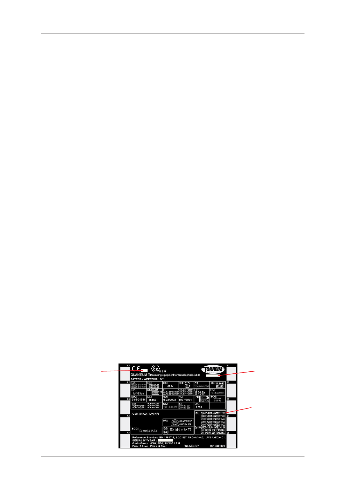
1.6.1 DISPENSER MARKING FOR THE ATEX DIRECTIVE
The dispenser is labelled by Tokheim in accordance with the requirements of
the ATEX Directive. This labelling includes:-
•The CE mark (CE conformity)
•The specific explosion protection mark, together with the mark indicating the
equipment group and category; and, relating to equipment group II, the letter
“G” (concerning explosive atmospheres caused by gases and vapours)
•The “Tokheim” name or logo and manufacturing location
•The dispenser type and serial number including the year of production
Labels can either be plastic stickers or metal plates and may vary according to
national requirements. A typical example of a label follows:-
0518 SIRA
or
0081 LCIE
DUNDEE
or
GRENTHEVILLE
“X” CONDITIONS refer to section 1.6.2
Document Ref 947571-001 Rev 2 Page 1-7
Page 14
Introduction Quantium 110 & 210 Installation Manual
1.6.2 SPECIAL CONDITIONS FOR SAFE USE
Certain models include Special Conditions for Safe Use which must be observed
prior to putting the dispensers into operation. Failure to do so will invalidate
the ATEX certification of the dispenser. These models can be identified by an
X at the end of the certificate number as shown on the dispenser typeplate.
The Special Conditions for Safe Use are identified in the ATEX EC TypeExamination Certificates and are repeated below:-
•Where a dispenser is supplied without hoses and/or nozzles, they shall be fitted
in accordance with:
-Hoses : EN1360 or EN13483
- Nozzles: EN13012
•When used for ethanol (blend) dispensing, the fuel specification must be less
than or equal to 85% ethanol, with minimum water content.
•The metering pumps and dispensers are designed for use in open air. Where a
metering pump or dispenser is positioned within a building, incorporated into
an enclosure, or integrated into a larger piece of equipment, additional measures
shall be taken to ensure that the zoning diagrams illustrated in the schedule
drawings are not compromised.
1.7 MID Dispensers
From mid 2007, T okheim dispensers may be shipped from European factories in accordance
with the Metrological Instruments Directive (MID). Such dispensers are calibrated and
the relevant seals stamped in the factory so that the dispensers are fit for trade immediately
upon installation without the need for a local W eights and Measures inspector to put them
into use.
The dispenser is shipped with its own “MID datasheet” which documents the serial numbers
of the prime components fitted in the dispenser. This datasheet must remain with the
dispenser. Similarly dispensers are shipped with a Declaration of Conformance to the
MID. This document must not be lost as it is an essential document to allow the continued
use of the dispenser.
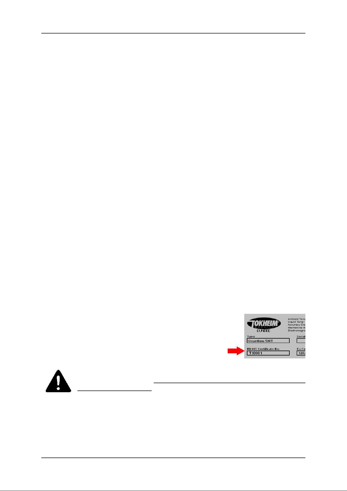
MID dispensers can be identified by the typeplate which
contains a reference to the MID certificate number as
shown:-
CHECKING THE SEALS
It is the responsibility of the Installer to check that all required seals are present and
correct prior to putting the dispenser into use. This includes seals on the pumping unit,
meter, pulser and calculator.
broken during installation.
Under no circumstances must any seals be disturbed or
METER CALIBRA TION
A calibration check should be performed during Commissioning (refer to section 6).
If a seal is damaged or missing, or if the calibration is outwith legal tolerances or in the
unlikely event that any repair is required to a pumping unit, meter, pulser or calculator
during installation, the factory MID verification is invalidated and a local National
verification will need to be performed before the dispenser can be used.
Page 1-8 Document Ref 947571-001 Rev 2
Page 15

Quantium 110 & 210 Installation Manual Site Preparation
CONTENTS
2 SITE PREPARATION.................................................................................................. 2-2
2.1 General................................................................................................................ 2-2
2.1.1 Zoning Diagrams ................................................................................ 2-2
2.2 Q110 and Q210 Hose and Pump Configurations................................................ 2-5
2.3 Hydraulic Connections ....................................................................................... 2-7
2.3.1 TQP Connections ............................................................................... 2-7
2.3.2 PAS V3 Connections .......................................................................... 2-8
2.3.3 Submerged Connections ....................................................................2-11
2.3.4 Q210 SDS Connections .................................................................... 2-12
2.3.5 Vapour Recovery Connections ......................................................... 2-12
2.4 Electrical Connections ...................................................................................... 2-16
Document Ref 947571-001 Rev 2 Page 2-1
Page 16

Site Preparation Quantium 110 & 210 Installation Manual
2 SITE PREP ARATION
2.1 General
Tokheim dispensers must only be installed on a level island or forecourt surface.
The ground plan will depend on the model ordered. See drawings in Section 3. Refer to
separate LPG Dispenser Manuals for information on LPG dispenser classifications.
VENTILATION
There are no vapour traps in the structure of the dispenser. The hydraulic cabinet is
ventilated via the hydraulic doors. Note : The hydraulic doors must not be blocked
during installation.
VAPOUR BARRIERS
Hazardous areas, as defined in this manual, are applicable only when the dispenser is
located in open air. The control of the hazardous areas in and around the fuel dispenser is
by the use of Vapour Barriers. No specific precautions are taken to reduce the Zone 1
classification of the internal hydraulic housing of the dispenser.
2.1.1 ZONING DIAGRAMS
Quantium 110 and 210 dispensers comply with the requirements of the ATEX
Directive 94/9/EC by conforming to PrEN13617-1.
The classification of vapour barriers are indicated in the following diagrams.
The zone classifications shown are always the highest applicable to that location
within the dispenser. The zone drawings respect the zones created by the use of
vapour recovery systems. No fuel pipes pass through any vapour barrier except
dispensers with Mechanical Registers where a drive shaft passes through the
airgap. Cables glands and blanking plugs used in the vapour barriers are certified
to an equivalent protection rating.
Page 2-2 Document Ref 947571-001 Rev 2
Page 17
Quantium 110 & 210 Installation Manual Site Preparation
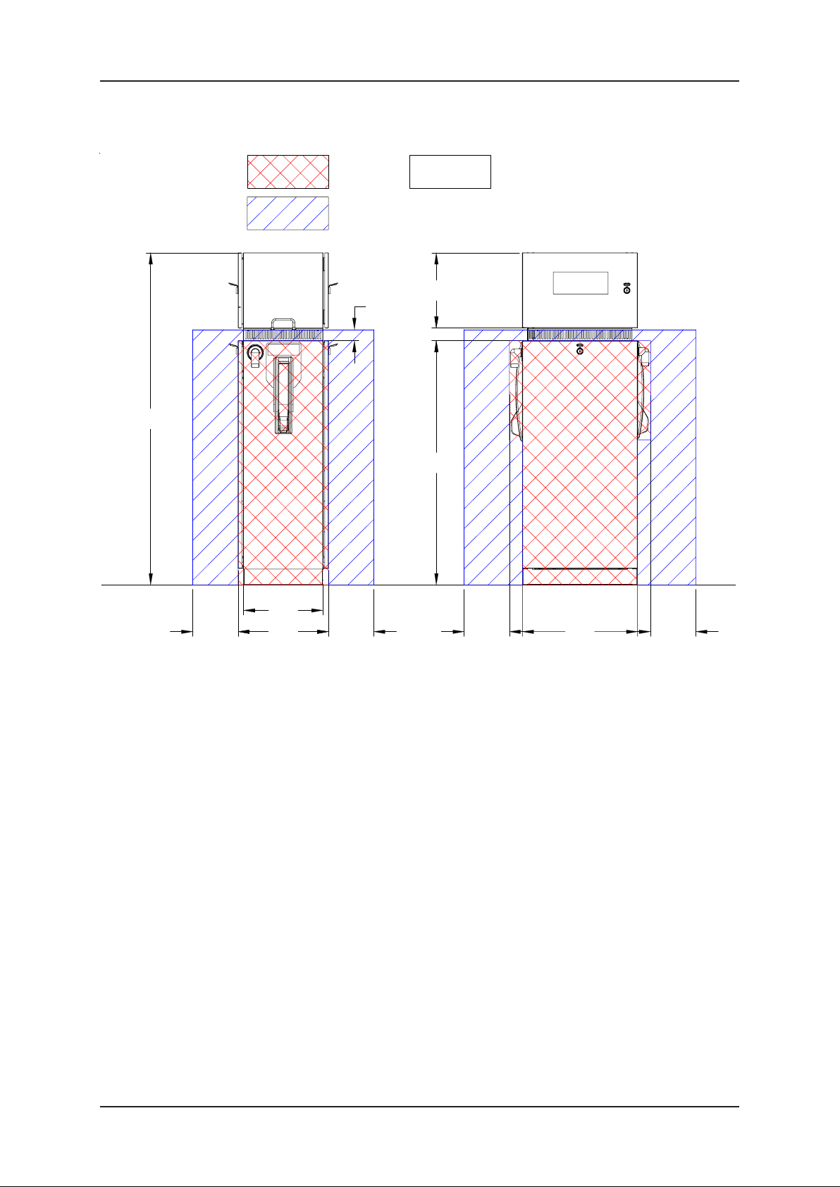
Q110 DISPENSER
1471
Zone
2
Zone 1
Zone 1
Zone 2
Zone
2
50
328.5
62
1080
Non-hazardous zone
Calc Head
Zone
2
Hydraulic
housing
Zone 1
Zone
2
Island Level
350
200 200
200 200
509427
Note:- On this dr awing all zone 2 areas are external of the dispenser.
Zone 1 is internal in the dispenser.
Document Ref 947571-001 Rev 2 Page 2-3
Page 18
Site Preparation Quantium 110 & 210 Installation Manual
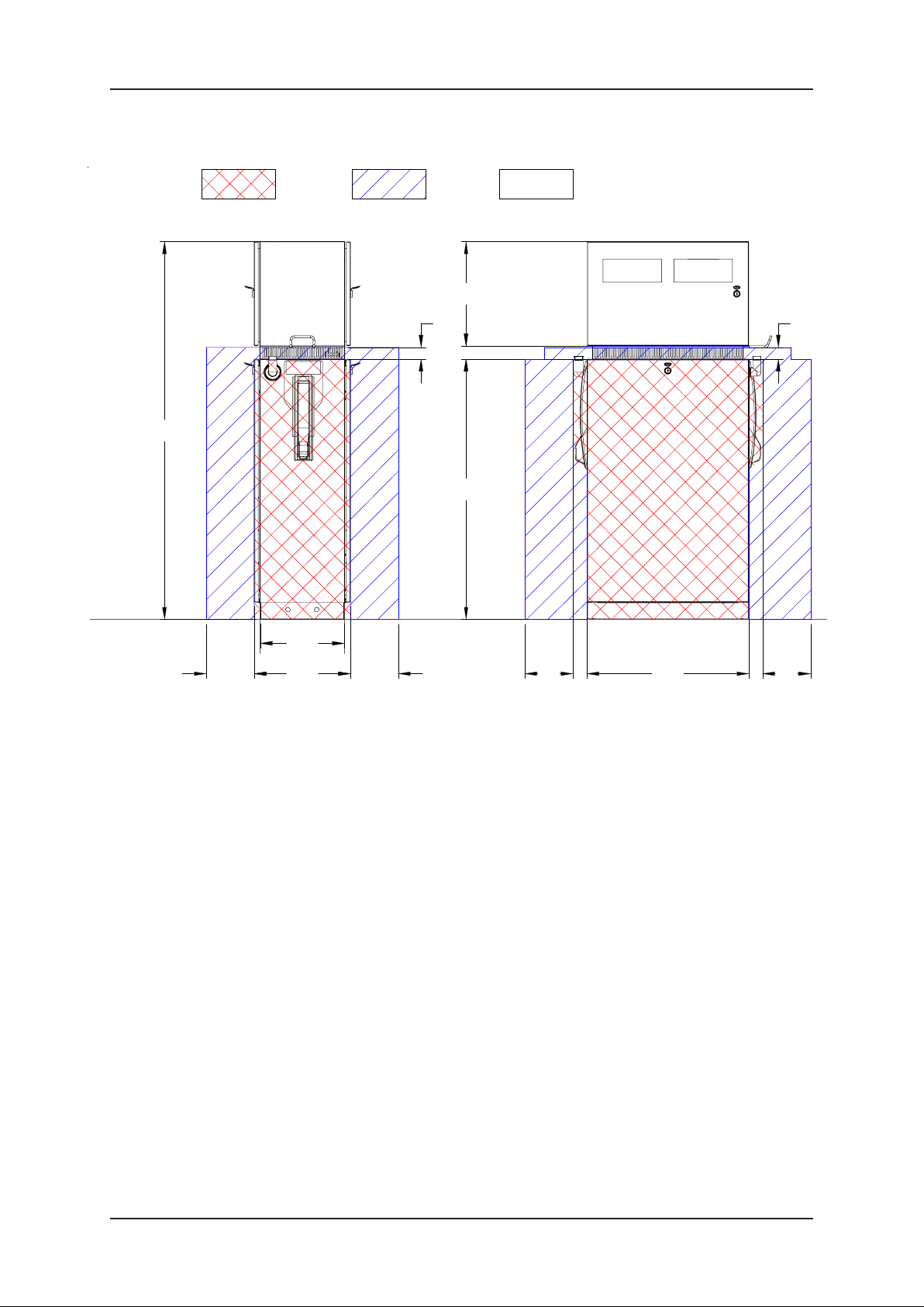
Q210 DISPENSER
1570.5
Island Level
Zone
2
Zone 1
Zone 1
350
Zone
2
50
432
56.5
1080
Zone
2
Non-hazardous zoneZone 2
Calc Head
Zone 1
Hydraulic
housing
50
Zone
2
200 200
Note:- On this drawing all zone 2 areas are external of the dispenser.
Zone 1 is internal in the dispenser.
673427
200200
Page 2-4 Document Ref 947571-001 Rev 2
Page 19
Quantium 110 & 210 Installation Manual Site Preparation
g
g
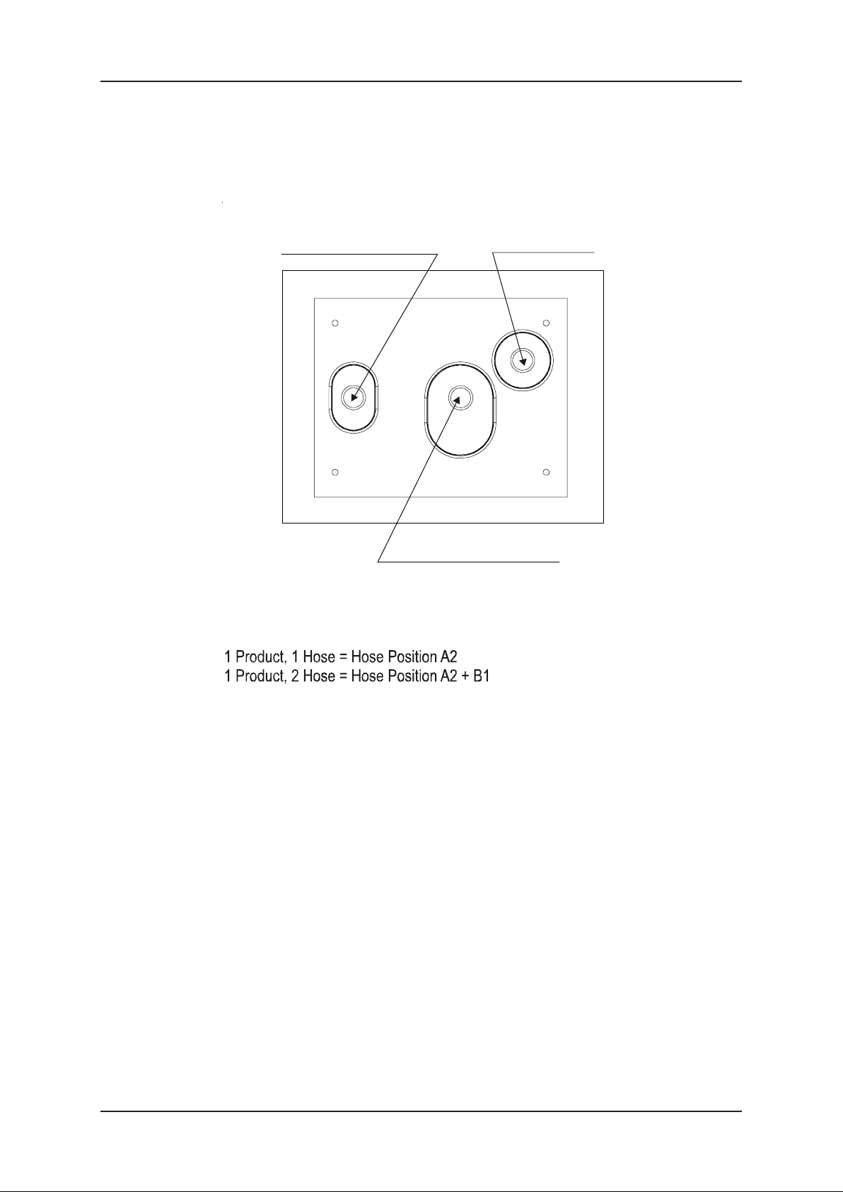
2.2 Q110 and Q210 Hose and Pump Configurations
The diagram below shows the possible functioning positions of the Q110 dispenser.
Vapour recovery (default)
or
Suction pipe for P AS V3
Electrical supply
Side B
B1
B2
A1
Hose outlet positions
Any Product + 1 Hose =
Any Product + 2 Hose =
A2
Side A
Product pipe only for TQP
TQP Low Pow e r 40 o r 40/80 or 80
P ASV3 High Power 130
Submer
ed 40 or 40/80 or 80 or 130
PASV3 High Power 40 or 80, Shared 130
Submer
ed 40 or 40 /80 or 80 or 13 0
Document Ref 947571-001 Rev 2 Page 2-5
Page 20
Site Preparation Quantium 110 & 210 Installation Manual
g
g
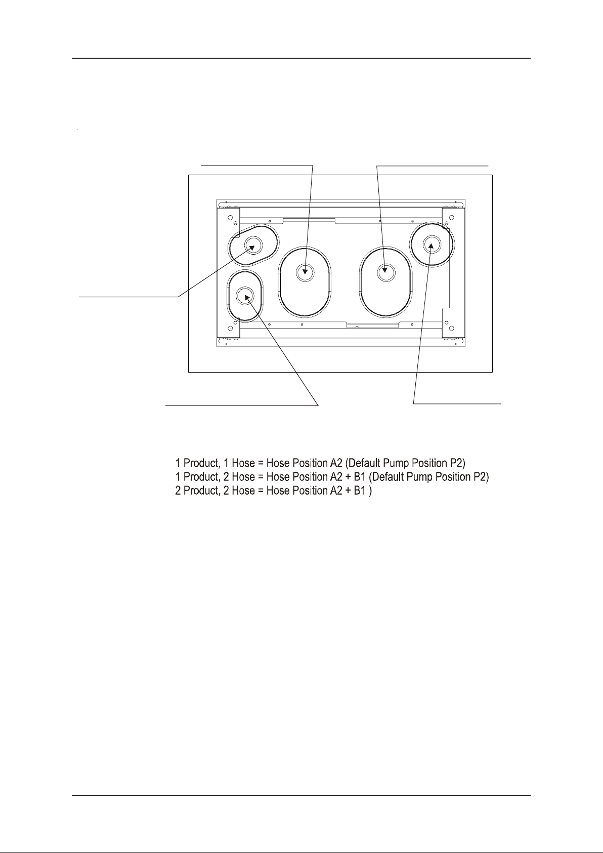
The diagram below shows the possible functioning positions of the Q210 dispenser.
Vapour Recovery
product 1 (only if return
line to product) or
Satellite connection
product 1
Vapour Recovery (Default) or
Satallite connection product 2
Product pipe 1 with TQP
or
Suction pipe for P AS V3
B1
A1
P1
Product pipe 2 with TQP
or
Satellite produ c t 2
Side B
B2
P2
A2
Side A
Electrical Supply
Hose outlet positions
Any Product + 1 Hose =
Any Product + 2 Hose =
TQP Low Power 40 or 40/80 or 80
PASV3 High Power 130
Submer
ed 40 or 40/80 or 80 or 130
PASV3 High Power 40 or 80 or Shared 130
Submer
ed 40 or 40/80 or 80 or 130
Page 2-6 Document Ref 947571-001 Rev 2
Page 21
Quantium 110 & 210 Installation Manual Site Preparation
2.3 Hydraulic Connections
The suction pipes are accessible from either side of the Dispenser. Different types of
hydraulic connection are available depending on the dispenser configuration.
Please note : If the inlet riser pipe has a female connection, an adaptor must be used
(1.5” or 2”).
If an adaptor is used, the dimensions shown will need to be reduced (maximum 36mm).
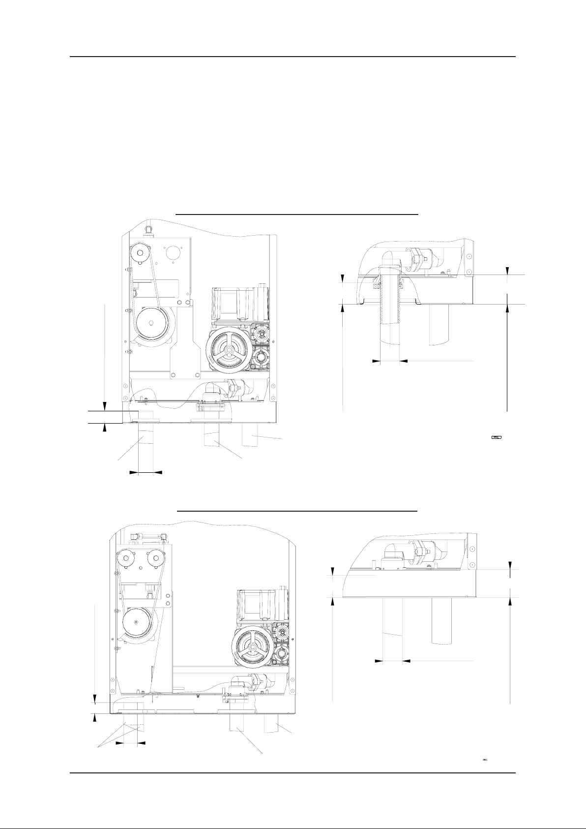
2.3.1 TQP CONNECTIONS
Q110 Dispenser with TQP (Standard configuration)
Riser VR pipe height (Std)
40
Vapour
Recovery
pipe
55.5
Ø1.5"
NEW DRA WINGS REQUIRED
Electrical Supply
Suction pipe
Ø1"
End threaded (VR pipe)
Riser knee height
(Ø40/49)
Dimensions shown from the bottom of base
Suction pipes
Q210 Dispenser with TQP (Standard configuration)
70 Min - 90 Max
Riser pipe height
55.5
70 Min - 90 Max
NEW DRA WINGS REQUIRED
Suction pipes
Ø1.5"
Riser VR pipe height (Std)
40
Electrical supply
Vapour
recovery
pipes
Document Ref 947571-001 Rev 2 Page 2-7
Ø1"
End threaded (VR pipe)
Suction pipes
Riser knee height
(Ø40/49)
Dimension shown from the bottom of chassis.
Riser pipe height
Page 22
Site Preparation Quantium 110 & 210 Installation Manual
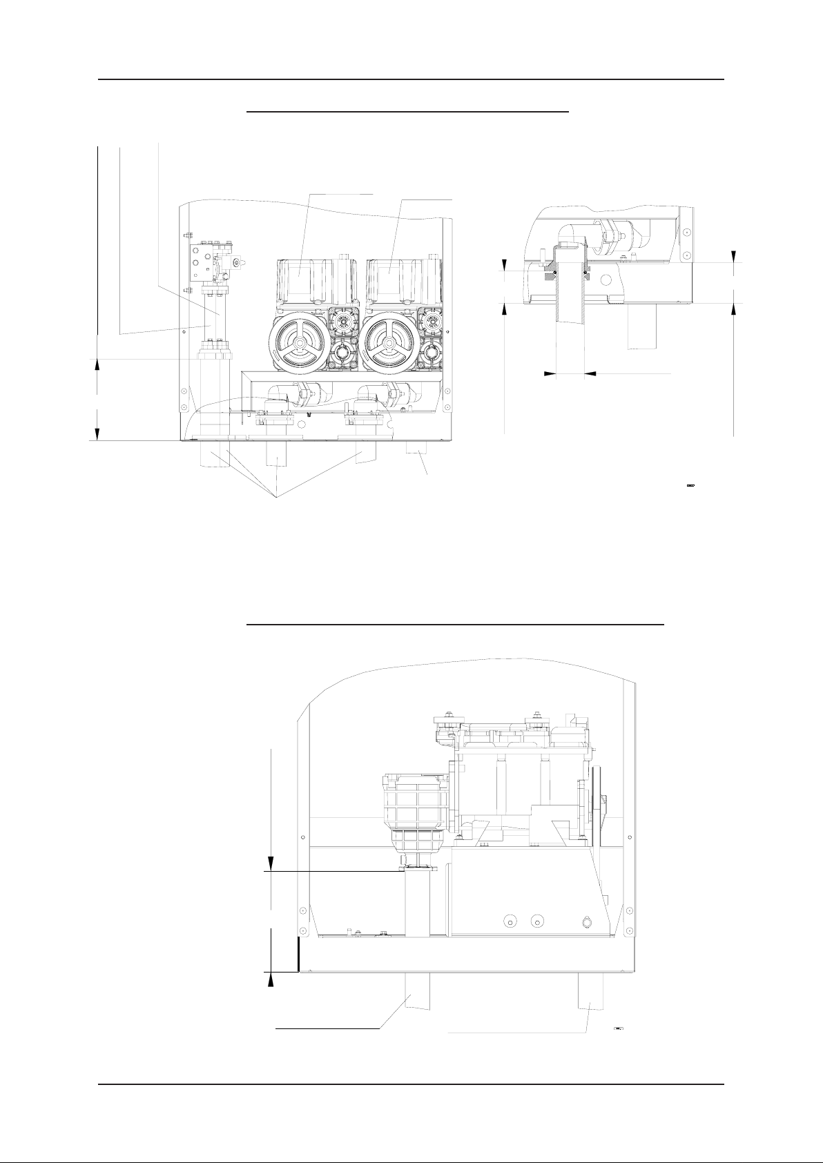
Q210 Dispenser with TQP & Satellite Connection
201
Riser flange connection height
Satellite connection - Product 2
Accessible from Side A
Satellite connection - Product 1
Accessible from Side B
Product 1
NEW DRA WINGS REQUIRED
Suction pipes
Product 2
Electrical supply
55.5
Suction pipe
Ø1.5"
Riser knee height
(Ø40/49)
Dimension shown from the bottom of chassis.
70 Min - 90 Max
Riser pipe height
2.3.2 PAS V3 CONNECTIONS
Q110 & Q210 Dispensers with PAS V3 (Standard configuration)
Riser filter height
201
Product 2
Side A
Suction pipe
Electrical supply
Dimensions shown from the bottom of the base
Page 2-8 Document Ref 947571-001 Rev 2
Page 23
Quantium 110 & 210 Installation Manual Site Preparation
Q110 & Q210 Dispensers with PAS V3 & Satellite Connection
Riser flange connection height
201
Satellite connection
Accessible from Side A
Riser filter height
201
Dimensions shown from the bottom of the base
PAS V3 Standard Suction & Submerged Hydraulic Connection
(without flexible coupling)
78
M10
Side A
Suction pipe
Product 2
Electrical supply
Filter Level
82
201
Driptray
height
70
Island Level
Document Ref 947571-001 Rev 2 Page 2-9
Page 24

Site Preparation Quantium 110 & 210 Installation Manual
PAS V3 Suction Connection - Flexible Coupling to 1.5” O-Ring
Compression Flange
Ø50
Flexible coupling to 1.5"
O-ring compression
flange
O-ring seal level
101
max
70
Driptray
height
78
Island Level
PAS V3 Suction Connection - Flexible Coupling to 1.5” Female Thread
Rc 1.5"
Ø38
Option - Flexible coupling to
1.5" female thread
O-ring seal level
70
Driptray
height
78
Island Level
Page 2-10 Document Ref 947571-001 Rev 2
Page 25

Quantium 110 & 210 Installation Manual Site Preparation
2.3.3 SUBMERGED CONNECTIONS
Standard Submerged Connection
Riser nut coupling height
NEW DRA WINGS REQUIRED
133
Riser shear valve height
Filter Level
117
201
Ø1.5"
(40/49)
Dimensions shown from the bottom of the base
Submerged Connection with Nefit Adaptor & Tokheim Shear Valve
End threaded
Adapter NEFIT
Pipe 903583
Driptray
70
height
Island Level
117
Document Ref 947571-001 Rev 2 Page 2-11
Page 26

Site Preparation Quantium 110 & 210 Installation Manual
2.3.4 Q210 SDS CONNECTIONS
With Breakaway & Cradle Without Breakaway or Cradle
Riser height from base
Riser height from base
201
201
117
Breakaway
2.3.5 VAPOUR RECOVERY CONNECTIONS
Standard VR Connection
Connection
flange level
For M8 screw
Island level
40
Page 2-12 Document Ref 947571-001 Rev 2
78
Page 27

Quantium 110 & 210 Installation Manual Site Preparation
VR Connection with Risbridger Shear Valve Option
Insulation Sleeve
Flange 1" 78mm
M10 Nut
Risbridger Shear Valve
900758-003
Gasket
901320-001
900011-004
Nipple
U Clamp
NOTE : All threads must be
sealed using Loctite 577
901859
901772
906069
903184
G1" VR Pipe
with male thread
900015-022
901596
Underside of dispenser
17
97.5
Terminate VR pipe
99mm below dispenser
M10x45 Bolt
Flange on Dispenser
VR Flexi
Driptray
height
70
99
IMPORTANT
Assembly below the shear point
must be secured to the ground
frame (NOT dispenser frame)
SPECIAL INFORMATION RELATING TO HIGH BLEND ETHANOL
FUELS (HBEF) & VAPOUR RETURN (VR) RETURN LINES
Following extensive explosion safety tests with HBEF by PTB, Tokheim
recommends all pipework back to the vapour space of the HBEF storage tank
should be protected by special flame arresters.
The vapour return line to the underground storage tank should be protected in
the event of a vehicle collision with a dispenser and also for maintenance
operations. The flame arrester(s) in the dispenser VR pump do not meet this
requirement.
An additional flame arrester must be positioned under the dispenser and must
be protected from potential damage during a vehicle collision so it remains
connected to the vapour return line to the tank in the event that the dispenser is
knocked off the island.
Note : This flame arrester is a r equirement of the installation, not a r equirement
of the dispenser.
If the Stage II VR return lines are routed back to the HBEF tank then the VR
return line from the dispenser vapour recovery system should protect the tank
by including a flame arrester.
Document Ref 947571-001 Rev 2 Page 2-13
Page 28

Site Preparation Quantium 110 & 210 Installation Manual
The correct type of flame arrester must be carefully selected:-
•Deflagration or detonation arrester dependent upon its position relative to the
anticipated end of line
•Inline type (unless it can be guaranteed to be at the end of line during maintenance
or after a vehicle collision)
•End of line types will need to be suitable for use with burning alcohol
•Arrester must be suitable for the correct Gas Group:-
- Ethanol blends 60% to 90% require Gas Group IIA Arresters
- Ethanol blends >90% require Gas Group IIB1 Arresters
•Arrester must be manufactured from materials suitable for use with ethanol and
bio-ethanol blended fuels
Tokheim offer two kits for use with Quantium dispensers to fullfil these
requirements, both kits using the inline deflagration flame arrester certified for
use with Gas Group IIB1 thus suitable for all percentage ethanol blends. The
kit must be installed in close proximity to the underside of the dispenser in
accordance with the drawings in this section.
Insulation Sleeve
Gasket
Flange 1" 78mm
M10 Nut
Nipple
•The standard kit includes an intentionally weak section above the arrester to
ensure that the device remains on the underground vapour pipe following a
vehicle collision
•The alternative kit includes a certified shear valve (with poppets) above the
arrester which additionally ensures that the line back to the tank is closed
following a vehicle collision
VR Connection with Shear Point & Flame Arrester for Ethanol
Kit 1 - Tokheim Part No 943143-001
900758-003
901859
901320-001
900011-004
901772
900015-022
901596
Underside of dispenser
M10x45 Bolt
Flange on Dispenser
VR Flexi
Driptray
height
70
Shear Valve
3
G1"- G
" Nipple
4
(Under Clamp)
Flame Arrester
U Clamp
NOTE : All threads must be
sealed using Loctite 577
904587
900416
943050-001
903184
with male thread
G1" VR Pipe
70
Terminate VR Pipe
70mm below dispenser
943143-001 Rev 1
86
IMPORTANT
Assembly below the shear point
must be secured to the ground
frame (NOT dispenser frame)
Page 2-14 Document Ref 947571-001 Rev 2
Page 29

Quantium 110 & 210 Installation Manual Site Preparation
VR Connection with Risbridger Shear Valve & Flame Arrester for Ethanol
Kit 2 - Tokheim Part No 943143-002
Insulation Sleeve
900758-003
Gasket
Flange 1" 78mm
M10 Nut
901320-001
900011-004
Nipple
Risbridger Shear Valve
U Clamp
3
G1"- G
" Nipple
4
(Under Clamp)
Flame Arrester
943050-001
NOTE : All threads must be
sealed using Loctite 577
901859
901772
906069
903184
900416
G1" VR Pipe
with male thread
900015-022
M10x45 Bolt
901596
VR Flexi
Driptray
height
Underside of dispenser
17
152.5
Terminate VR pipe
154mm below dispenser
943143-002 Rev 1
IMPORTANT
Assembly below the shear point
must be secured to the ground
frame (NOT dispenser frame)
70
154
Document Ref 947571-001 Rev 2 Page 2-15
Page 30

Site Preparation Quantium 110 & 210 Installation Manual
2.4 Electrical Connections
The electrical connection to be established between the kiosk and the dispenser exists in
different configurations. The mains connection (power from the mains supply panel to
the dispenser) and the data connection (link between forecourt controller and calculator)
are customer, country and configuration specific. The number of cores and the cross
section of the cable will be specified, as will the cable construction (armoured or Explosion
proof) and guidance troughs, channels or cable trunks have to be carried out in accordance
with national technical regulations.
Page 2-16 Document Ref 947571-001 Rev 2
Page 31

Quantium 110 & 210 Installation Manual Drawings
CONTENTS
3 DRAWINGS................................................................................................................... 3-2
3.1 Q110 Dispenser................................................................................................... 3-2
3.1.1 Q110 Dispenser Dimensions .............................................................. 3-2
3.1.2 Q110 Ground Plans ............................................................................ 3-3
3.1.3 Q110 Retention Tray Assembly.......................................................... 3-4
3.1.4 Q110 Ground Fixing........................................................................... 3-4
3.2 Q210 Dispenser................................................................................................... 3-5
3.2.1 Q210 Dispenser Dimensions .............................................................. 3-5
3.2.2 Q210 Ground Plans ............................................................................ 3-6
3.2.3 Q210 Retention Tray Assembly ......................................................... 3-7
3.2.4 Q210 Ground Fixing .......................................................................... 3-7
3.3 Q210 SDS Dispenser .......................................................................................... 3-8
3.3.1 Q210 SDS Dimensions ....................................................................... 3-8
3.3.2 Q210 SDS Ground Plan ..................................................................... 3-9
Document Ref 947571-001 Rev 2 Page 3-1
Page 32

Drawings Quantium 110 & 210 Installation Manual
3 DRAWINGS
3.1 Q110 Dispenser
3.1.1 Q110 DISPENSER DIMENSIONS
Display
1471
1339
1137
1080
Product2
Side A
506
509
(Base)
(Cladding)
Side A is the side where t he pulley is (if TQP config).
Nozzle
825
Hose Hook
1132
Sprng Mast
2123
Island level
(Base)
(Cladding)
Side A
Side B
350
427
Side B is the side where the air vent outlet is.
For option "Display one side only", display is on side 'A'.
With single hose models, the hose is always on the right hand side when facing side A.
Outlet elbows are oriented upwards for springmast and oriented downwards for hose hook.
Page 3-2 Document Ref 947571-001 Rev 2
Page 33

Quantium 110 & 210 Installation Manual Drawings
3.1.2 Q110 GROUND PLAN
Product pipe only for TQM
Vapour recovery or Suction
Side B
Electrical supply
pipe for PAS V3
350
325
250
25
175
Side - Product outlet
(product 2) ( Std)
Bolting holes
Side A
88
212.6
428.5
465.5
506
Dimensions shown are from bottom of base.
40.5
Document Ref 947571-001 Rev 2 Page 3-3
Page 34

Drawings Quantium 110 & 210 Installation Manual
3.1.3 Q110 RETENTION TRAY ASSEMBLY
903944
3.1.4 Q110 GROUND FIXING
Leak plate option
Leak plate
(904188)
Washer Pl M10
(900008-014)
SECTION A-A
SCALE 1:1
Page 3-4 Document Ref 947571-001 Rev 2
Page 35

Quantium 110 & 210 Installation Manual Drawings
g
g)
g)
g
g
3.2 Q210 Dispenser
3.2.1 Q210 DISPENSER DIMENSIONS
1032
Rigid mast
2410
Display
1570
1439
1137
1082
Side A
Product 1
(Base)
673
Nozzle
825
Product 2
(Cladding)
Springmast
2223
Hose Hook
1133
Side A
Island level
(Base)
(Cladding)
NOTES:Side A is the side wh ere t he pulleys are (if TQP config).
When facin
Side A the pump pul ley is on the right hand side (if PASV3 co nf i
When facing Side A, filter brackets are on th e right hand side (if submerged confi
For option "Dis play one side only" dis plays are on side A
Product outlet always on side 2 for single product
Outlet elbows are oriented upwards for sprin
For retainin
hose option, the standard one is wit h th e hook otherwise ot her options are eithe r
mast and orient ed downwards for ho s e hook
spring or rigid mast.
Side B
350670
427
Document Ref 947571-001 Rev 2 Page 3-5
Page 36

Drawings Quantium 110 & 210 Installation Manual
3.2.2 Q210 GROUND PLAN
Bolting holes
Vapour recovery product 1 (only
if return line per product) or
Satellite connection product 1
Vapour recovery (default)
or Satellite connection
product 2
249
112
Product pipe 1 with TQP
or Suction pipes for
PASV3
Side B
Side A
432
572
595
635
670
Dimensions shown are from base of chassis
Product pipe 2 with TQP
or Satellite product 2
212
Electr ic al su pp ly
35
88
25
175
252
325
350
Side-Product outlet(product2)(std)
Page 3-6 Document Ref 947571-001 Rev 2
Page 37

Quantium 110 & 210 Installation Manual Drawings
3.2.3 Q210 RETENTION TRAY ASSEMBLY
903930
3.2.4 Q210 GROUND FIXING
Base of the dispenser
Washer Pl M10
(900008-014)
Leak plate
(903567)
Leak plate option
Apply SILICON sealant all around the leak plate before placing the dispenser.
Ensure the seal between the leak plate and dispenser is complete to avoid water
ingress.
Document Ref 947571-001 Rev 2 Page 3-7
Page 38

Drawings Quantium 110 & 210 Installation Manual
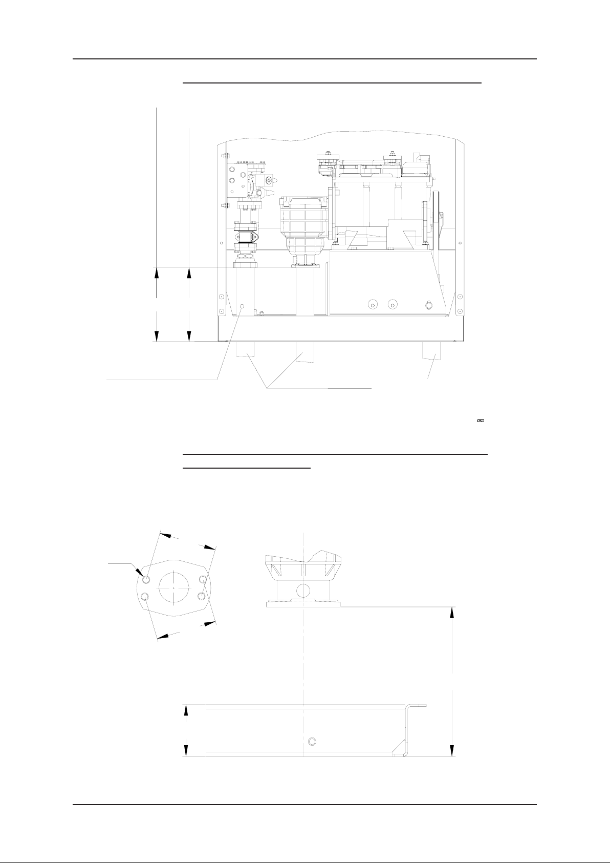
3.3 Q210 SDS Dispenser
3.3.1 Q210 SDS DIMENSIONS
Stripped do wn satellite with breakaway and cradle
Lockheight
Overall height
1085
Cradle height
106
Stripped down satellite without breakaway or cradle
Nozzle height
1038.5
830
Side B
Side B
Cradle
250 245
x 250
366
Hoseoutlet
1030.5
SideA
Cladding
Lock position
Overall height
1086
Side A
250
Embedding Plate
1038.5
Nozzleheight
830
SideB
Side B
250
365.9
Hose outlet
1030.5
Page 3-8 Document Ref 947571-001 Rev 2
Page 39

Quantium 110 & 210 Installation Manual Drawings
3.3.2 Q210 SDS GROUND PLAN
Top view
Electrical supply
Suction pipe
68
225
250
Nozzle side
125
225
250
Dimensions taken from the base
42
12
125
42
12
Base of the satellite
182
Hose outlet side
Document Ref 947571-001 Rev 2 Page 3-9
Page 40

Drawings Quantium 110 & 210 Installation Manual
This page is intentionally blank
Page 3-10 Document Ref 947571-001 Rev 2
Page 41

Quantium 110 & 210 Installation Manual Packaging & Handling
CONTENTS
4 PACKAGING & HANDLING..................................................................................... 4-2
4.1 Shipping Documentation .................................................................................... 4-2
4.2 Packaging............................................................................................................ 4-2
4.2.1 Unpacking .......................................................................................... 4-2
4.3 Inventory Inspection ........................................................................................... 4-2
4.3.1 Checking List ..................................................................................... 4-3
4.4 Dispenser Weights .............................................................................................. 4-3
4.4.1 Q110 Dispenser Weights .................................................................... 4-3
4.4.2 Q210 Dispenser Weights .................................................................... 4-3
4.5 Handling.............................................................................................................. 4-3
4.6 Access the Hydraulic Area.................................................................................. 4-4
4.7 Access the Calculator Head ................................................................................ 4-4
4.8 Access the Junction Box..................................................................................... 4-5
4.8.1 Bernstein Junction Box ...................................................................... 4-5
Document Ref 947571-001 Rev 2 Page 4-1
Page 42

Packaging & Handling Quantium 110 & 210 Installation Manual
4 PACKAGING & HANDLING
4.1 Shipping Documentation
The following documents will accompany every delivery:-
•Shipping List
•Packing/Checking List
•CE Sticker
•Certificate of Conformity
The Serial Number on the dispenser should be identical to the Serial Number on the
Shipping List, CE sticker and Certificate of Conformity . Please inform Tokheim UK Ltd
before unpacking if there are any discrepancies in the notation.
4.2 Packaging
The type of packing depends on the destination of the goods. All products containing a
frame are fixed on a pallet by means of screws and by the use of beams or blocks screwed
onto the frame.
The goods are protected from moisture and scratching by bubble wrap and polystyrene
corner blocks and a standard carton is used for packing. Where the use of a forklift truck
or pallet truck is necessary, special arrangements make this possible through the use of
pallets, beams, dispenser beam bridges or blocks.
All separate components belonging to the same delivery are packed together.
4.2.1 UNPACKING
When the dispensers arrive at the installation site, the unpacked units should be
inspected for possible shipping damage. If damage is evident, it must be reported
to the carrier. Shipping damage is not covered under the Tokheim warranty
policy.
After checking the equipment, the dispenser may be unwrapped. Cladding is
packed in such a way that paint, screening and stickers are protected. T ake care
when unwrapping so that these elements are not damaged.
After unwrapping, the dispensers must be checked for any faults or damage.
Any faults or damage found must be reported to the Installation Supervisor
immediately.
Make sure that all packing materials are removed from the service station. It is
recommended that you discuss this with the station’s supervisor.
4.3 Inventory Inspection
After unpacking and prior to installation, the delivered equipment should be inspected to
ensure that all the required materials are on hand, and the dispensers have all the ordered
options and markings. If discrepancies in dispenser options and markings are evident,
contact Tokheim France.
Page 4-2 Document Ref 947571-001 Rev 2
Page 43

Quantium 110 & 210 Installation Manual Packaging & Handling
4.3.1 CHECKING LIST
Proper installation of today’s sophisticated electronic dispensing systems is
essential to ensure trouble-free performance. Therefore, T okheim has established
inspection and check-out procedures to be followed to ensure correct equipment
installation.
All products within a package are listed on the Checking List. Follow the
procedure on the Checking List to ensure all required components have been
delivered then return the completed Checking List to the Quality Dept., T okheim,
Grentheville, France.
4.4 Dispenser Weights
The following weights are approximate and will vary according to options fitted.
4.4.1 Q110 DISPENSER WEIGHTS
•One Hose Dispenser : 120kg
4.4.2 Q210 DISPENSER WEIGHTS
•Two Hose Dispenser : 190kg
4.5 Handling
The recommended procedure for safe handling of the dispenser is by use of a forklift
under the pallet.
The installer must supply all handling equipment and ensure safe working practice at all
times.
Document Ref 947571-001 Rev 2 Page 4-3
Page 44

Packaging & Handling Quantium 110 & 210 Installation Manual
4.6 Access the Hydraulic Area
The following instructions detail the procedure to be followed for the removal of the
hydraulic access panel(s) to allow safe access to the dispenser hydraulics.
INSTRUCTIONS
1) Locate the key for the hydraulic access panel.
2) Unlock the hydraulic access panel.
3) Carefully lift out the panel.
Note - the panel is still attached by a retaining cord, earth and/
or electrical cables.
4) Disconnect the retaining cord, earth and/or electrical cables from
the panel door.
5) Lift up the panel to release from the drive pins in the base and
remove the hydraulic access panel completely.
6) Repeat for opposite side of dispenser as required.
7) Place the hydraulic access panel(s) in a safe position.
8) To re-fit the hydraulic access panels, follow the instructions in
reverse.
4.7 Access the Calculator Head
The following instructions detail the procedure to be
followed for the safe access to the calculator head.
INSTRUCTIONS
1) Locate the key for the calculator head door.
2) Unlock the calculator head door on the relevant side of the
dispenser and carefully open it.
Note : the door is still attached by electrical and/or earth cables.
3) Secure the calculator head door in the open position.
4) Repeat for opposite side of dispenser as required.
5) To close and lock the calculator head door, follow
the instructions in reverse.
Note : ensure the electrical and/or earth cables
remain inside when closing the calculator head
door.
Page 4-4 Document Ref 947571-001 Rev 2
Page 45

Quantium 110 & 210 Installation Manual Packaging & Handling
4.8 Access the Junction Box
4.8.1 BERNSTEIN JUNCTION BOX
The following instructions detail the procedure to be followed to allow safe
access to the junction box connections.
INSTRUCTIONS
1) Follow the instructions given to access the hydraulic
area.
2) Locate the Junction Box in the hydraulic area.
3) Using a screwdriver, loosen and remove the four
screws on the junction box cover and remove
completely.
4) Refer to the wiring diagrams in section 5.
5) To re-fit the junction box cover , follow the instructions
in reverse.
Document Ref 947571-001 Rev 2 Page 4-5
Page 46

Packaging & Handling Quantium 110 & 210 Installation Manual
This page is intentionally blank
Page 4-6 Document Ref 947571-001 Rev 2
Page 47

Quantium 110 & 210 Installation Manual Installation
CONTENTS
5 INSTALLATION........................................................................................................... 5-2
5.1 General................................................................................................................ 5-2
5.2 Identification of Side A....................................................................................... 5-2
5.3 Lifting ................................................................................................................. 5-3
5.4 Placement............................................................................................................ 5-3
5.4.1 By Forklift .......................................................................................... 5-4
5.4.2 Fixing to Ground ................................................................................ 5-6
5.4.3 Earthing .............................................................................................. 5-7
5.5 Hydraulic Connections ....................................................................................... 5-8
5.5.1 Pipework - Suction Dispensers with Internal Filter ........................... 5-8
5.5.2 Pipework - Suction Dispensers with External Filter ........................ 5-10
5.5.3 Pipework - Submerged Dispensers................................................... 5-12
5.6 Electrical Connections ...................................................................................... 5-12
5.6.1 Direct wiring into Terminal Rail - WWC......................................... 5-13
5.6.2 Junction Box Wiring......................................................................... 5-16
5.6.3 Communications Wiring (WWC Head only) ................................... 5-19
5.6.4 OPT Communications option ........................................................... 5-24
Document Ref 947571-001 Rev 2 Page 5-1
Page 48

Installation Quantium 110 & 210 Installation Manual
5 INSTALLATION
5.1 General
Before the dispenser can be installed, the Safety Instructions as described in Section 1.5
and the Installation Instructions in this section must be carefully read.
Follow unpacking instructions in Section 4.2.1.
After unwrapping and before installation, the dispensers must be checked for any faults or
damage. Any faults or damage found must be reported to the Installation Supervisor
immediately.
NOTE: IF USING SUBMERGED PUMPS, THE CONTROL MUST BE
COMPLETELY ISOLATED DURING ALL PHASES OF INSTALLATION.
The following checks need to be made before starting the installation :-
•Check that the electric cabling and the piping arrangements have been made in accordance
with the Installation drawings in section 3.
•Check that the leakage plates have been produced in accordance with the Installation
drawing. Any differences or defects should be reported to the Installation Supervisor
immediately. The function of the leakage plate is to drain leakages to the outside of the
dispenser where they act as a warning to the station attendant.
•Check that all flame arresters are correctly installed according to the drawings.
5.2 Identification of Side A
The different sides of the dispenser referred to in this manual are described as follows:-
•Side A of the dispenser has the pulleys and inlet connections (visible upon removal of
hydraulic doors). All single hose models have the hose on the right hand side when facing
side A.
Side A
Page 5-2 Document Ref 947571-001 Rev 2
Page 49

Quantium 110 & 210 Installation Manual Installation
•Side B of the dispenser has the electrical supply (visible upon removal of hydraulic doors).
All single hose models have the hose on the left side when facing side B.
Side B
5.3 Lifting
The responsibility for carrying out the procedures described
in this manual lies with the persons lifting and placing the
dispenser.
Lifting equipment can be
The installer must supply all lifting equipment and ensure
safe working practice at all times.
Quantium 110 & 210 dispensers can be lifted by forklift
truck under the pallet.
5.4 Placement
hazardous, and must be
rated to lift the weight of
the dispenser. Equipment
could fall and cause
severe injury or death.
St and clear from the
dispenser when lifting and
lowering.
Before placement on the island can take place, the following
procedures must be carried out:-
•Check that the electric cabling and piping arrangements have been made in accordance
with the Installation drawing
• Check the pipes have been flushed before connecting the hydraulic components (if
necessary, contact the tank installer)
•Removal of stop plugs on fuel and vapour recovery pipes
•Preparation of mounting frame
•Fitting of seals for cable, fuel and vapour recovery pipe access
•Sealing of non-used holes
IMPORTANT - Make sure Side A of the dispenser is positioned onto the island per
customer specifications. See Section 5.2 for locating Side A.
Document Ref 947571-001 Rev 2 Page 5-3
Page 50

Installation Quantium 110 & 210 Installation Manual
5.4.1 BY FORKLIFT
1) Lift the dispenser using a forklift truck under the pallet. Position the dispenser
close to the dispenser island. Ensure side A with the inlet connections is correctly
positioned - refer to section 5.2 for the identification of side A.
2) Remove the hydraulic doors. Unbolt the pallet from the base of the dispenser.
IMPORT ANT - Wher e supplied, the leak plate must be placed in the ground PRIOR
to positioning the dispenser . Once placed, the leak plate must be sealed to the ground
frame and to the dispenser using a suitable sealant.
Page 5-4 Document Ref 947571-001 Rev 2
Page 51

Quantium 110 & 210 Installation Manual Installation
3) Where supplied, place the leak plate onto fixing studs provided on the island
prior to positioning the dispenser ensuring the riser pipes and cables pass through
the correct holes in the leak plate.
Carefully lift the dispenser and position on the leak plate.
Leak Plate
4) IMPORTANT:Secure the dispenser to the ground as described in section 5.4.2.
Placement complete.
Document Ref 947571-001 Rev 2 Page 5-5
Page 52

Installation Quantium 110 & 210 Installation Manual
5.4.2 FIXING TO GROUND
The following information relates to a typical Tokheim dispenser, unmodified
by the user, with no additional advertisement boards, canopies or items added
to the dispenser. Any such modifications may affect the stability and have
warranty/liability consequences.
IMPORTANT:- Tokheim dispensers must be secured to the ground using
all 4 mounting positions provided in the driptray - refer to the gr oundplan
drawings in section 3 for mounting hole positions.
TYPICAL FIXING INTO CONCRETE (NO GROUNDFRAME)
M12 ANCHOR BOLT FOR
CONCRETE high tensile
WASHER
min thickness = 2mm
min dia = 25mm
Underside of
dispenser driptray
Min depth into
concrete = 100mm
100
TYPICAL FIXING INTO TOKHEIM GROUNDFRAME
WASHER
min thickness 2mm
min dia 25mm
Underside of
dispenser driptray
Tokheim groundframe
M10 BOLT high tensile
Nut insert
TYPICAL FIXING INTO THIRD PARTY GROUNDFRAME / SUMP
FRAME
M12 BOLT high tensile
Alternative to nut & washer :Welded nut on groundframe
with min. 5 captured threads
Underside of
dispenser driptray
Steel groundframe/
sump frame
WASHERS
min thickness = 2mm
min dia = 25mm
M12 NUT
Page 5-6 Document Ref 947571-001 Rev 2
Page 53

Quantium 110 & 210 Installation Manual Installation
5.4.3 EARTHING
Earthing requirements are dictated by local National regulations and must always
be observed.
Tokheim recommends the following guidelines as a minimum requirement:-
2
•6mm
•10mm
earth conductor(s) back to main site earth (up to 85m cable run)
2
earth conductor(s) back to main site earth (85 to 150m cable run)
The primary earth connection point for Quantium dispensers is the M2000T
Junction Box provided for installation cable connections. Threaded inserts or
studs (M8) are also provided in the base frame as an additional external
connection facility for an earthing or equipotential bonding conductor.
Earthing requirements are dependent upon the number of earth conductors
provided (one per power cable) and the types of cable used. For example,
where steel wire armour cables or MICC are used in conjunction with the
appropriate termination glands, no supplementary specific earth cable is likely
to be required. Where simple PVC covered cables are used, Tokheim
recommends an additional earth core is connected to the point provided on the
dispenser base frame.
IMPORTANT : It is the responsibility of the Installer to supply the earth
wire and ensure the dispenser is safely earthed.
The photograph below is an typical example of an earth connection point on a
Q210 dispenser (exact location and/or fixture may differ between dispenser
ranges):-
Document Ref 947571-001 Rev 2 Page 5-7
Page 54

Installation Quantium 110 & 210 Installation Manual
5.5 Hydraulic Connections
Connect all hydraulic and electric junctions according to the specifications as described
in this section and indicated on the drawings in Section 3.
Flow rates achieved are dependent upon the type of submerged pumping system used and
other site-specific conditions.
Note : The maximum pressure must not exceed 3.5 bar.
5.5.1 PIPEWORK - SUCTION DISPENSERS WITH INTERNAL FILTER
Connections to the fuel supply pipes and the vapour return lines are accessible
from side A of the dispenser (see section 5.2 for identification of sides).
TQP PUMPS WITH INTERNAL FILTER
Screw HFHS M8x25
Screw HFHS M8x30
O-Ring OD49, 00x6.00
Terminal Earth Clamp
O-Ring OD37, 47x5.33
Junction Flange
Flexi Pipe EPZ
Flange
Threaded Flange
M8 Self Lo ck Nut
Page 5-8 Document Ref 947571-001 Rev 2
Page 55

Quantium 110 & 210 Installation Manual Installation
1) Place the terminal earth clamp over the supply riser
pipe and tighten.
Add the threaded flange and O-ring OD49.
2) Place the elbow of the flexi pipe through
the hole of the flange. Connect to the
threaded flange resting on the supply
riser pipe using 3 M8x30 screws.
3) Tighten the screws on the terminal earth clamp and the
2 flanges.
4) Place the elbow of the flexi pipe through the
hole of the junction flange, then add the Oring OD37. Bend the flexi pipe until the
junction flange mates with the pump inlet.
5) Tighten the screws from the junction flange to the
pump inlet.
6) Repeat steps 1 to 5 for each hydraulic position as
required.
Document Ref 947571-001 Rev 2 Page 5-9
Page 56

Installation Quantium 110 & 210 Installation Manual
5.5.2 PIPEWORK - SUCTION DISPENSERS WITH EXTERNAL FILTER
Connections to the fuel supply pipes and the vapour return lines are accessible
from side A of the dispenser (see section 5.2 for identification of sides).
The dispenser is positioned with the filter box positioned above the relevant
fuel supply risers. If required, adapters should be fitted to the supply pipes.
The flexible connection (rigid for pressurised systems) should then be fitted
between the fuel supply risers and the filter box.
P AS V3 PUMPS WITH EXTERNAL FILTER BOX ONL Y
1) Remove the protective covers on the fuel supply riser pipe and on the filter
box.
WARNING : BEWARE OF FUEL SPILLAGE.
2) Cut the rubber manchet to suit the riser pipe diameter
and fit over the pipe to cover the hole in the driptray .
3) Apply a sealant compound to the fuel supply riser
and to the inside of the flexible coupling.
4) Fit the flexible coupling to the fuel supply riser pipe.
Note : Hand tighten only at this point
5) Insert the top hat filter (provided in the installation
kit) into the flexible coupling.
6) Manoeuvre the flexible coupling into the correct
position, ready for securing to the filter box.
7) Insert the gasket between the filter box and the flange
on the flexible coupling.
8) Fit the flange to the filter box using the two screws
provided in the installation kit.
Note : Hand tighten only at this point.
Page 5-10 Document Ref 947571-001 Rev 2
Page 57

Quantium 110 & 210 Installation Manual Installation
9) Use a large adjustable spanner to tighten and secure
the flexible connection to the fuel supply riser pipe.
10) Using a 15mm spanner or socket, tighten the two
screws on the flange.
11) Repeat steps 1 to 10 for each hydraulic position as
required.
Document Ref 947571-001 Rev 2 Page 5-11
Page 58

Installation Quantium 110 & 210 Installation Manual
5.5.3 PIPEWORK - SUBMERGED DISPENSERS
The Installer is responsible for supplying the riser
pipe to the heights given in section 2.4 and all
pipework and connections below the filter box
connection.
EXTERNAL FILTER BOX ONLY
1) The dispenser must be positioned directly above the
riser pipes and carefully lowered into position.
2) Remove the protective covers on the fuel supply riser pipe and on the filter
box.
WARNING : BEWARE OF FUEL SPILLAGE.
3) Connect the fuel supply pipe to the filter box or optional flange (where fitted).
4) Repeat for each hydraulic position as required.
5.6 Electrical Connections
During installation, the main switch must be switched off - ensure the main switch cannot
be switched on inadvertently.
The installation of the cables must be carried out carefully to ensure the Eex-norm is
enforced (insertion of cables via glands).
The electrical connections are compatible with all European installation practices and
typical country specific cable types. The following information is the Tokheim
recommended installation, however where differences exist in the standards relating to
installation according to country specific legislation, the local/national standards must be
employed. Electrical connections are made by either :-
•Direct wiring into a terminal rail in a WWC (refer to section 5.6.1):-
- Single Phase Suction
- Three Phase Suction
- Submerged
•Wired into a junction box in hydraulic area (refer to section 5.6.3):-
- Single Phase Suction
- Three Phase Suction
- Submerged
- Split Power option - Three Phase Suction
- Split Power option - Single Phase Suction
- Split Power option - Submerged
Page 5-12 Document Ref 947571-001 Rev 2
Page 59

Quantium 110 & 210 Installation Manual Installation
CABLING
The type of cabling used will differ by country according to local and/or national laws and
regulations. The drawings in this section show the minimum number of cores required in
cables and the minimum core cross sectional area. Cables with more than the minimum
can be used provided that the cables are suitable for use with the cable gland sizes fitted.
Individual cables can be combined provided that the minimum number of conductors
remains.
The maximum number of forecourt cables required will be :-
•One power cable for motor power supply
•One power cable for calculator and lighting supply
•One cable for dispenser communications
•One cable per side for OPTimum communications (optional Q210 only)
•One cable per submerged pump control signals (where applicable)
ELECTRONICS & LIGHTING PROTECTION
Tokheim recommends the use of a 2 pole thermal-magnetic device for protection of the
metering pump electronics. A fuse must NOT be used in the neutral conductor . Thermalmagnetic breakers or fuses must be capable of extinguishing a fault current of at least
4000A. Pump lighting and lighting switched remotely are optional.
MOTOR WIRING
The number of motors per dispenser will vary according to different models and options.
Always connect to the furthest left terminal first. Jumper sizes and positions vary according
to the number of motors connected.
5.6.1 DIRECT WIRING INTO TERMINAL RAIL - WWC
1) Follow the instructions given in section 4.7 to access the calculator head. Locate
the relevant terminal rail inside the head:-
•WWC - terminal rail located on side wall of WWC head
WWC
MOTOR
POWER
LIGHTS
MOTOR
POWER
Document Ref 947571-001 Rev 2 Page 5-13
CECLI
LIGHTS
Page 60

Installation Quantium 110 & 210 Installation Manual
2) Make the connections according to the correct wiring diagram shown in this
section.
IMPORTANT :- ENSURE THE CORRECT WIRING DIAGRAM IS
FOLLOWED.
3) When complete, ensure that all tools and unused materials are removed, close
the calculator door and lock.
4) Re-instate power to the dispenser and test its operation.
WWC - Single Phase Suction
TERMINALS IN
CALC HEAD
FORECOURT
WIRING
KIOSK
EQUIPMENT
MOTOR
POWER
PE N L1
3x2.5mm²
cable or MICC
* Note 1
Motor MCB
CALC**
POWER
FUSE
L L
2A
Calc** MCB
LIGHTS
POWER
N PEN PE
FUSE
5x1.5mm² cable
or
4x1.0mm² MICC
2A
Lights MCB
* Note 1
16A Motor Circuit Breaker for
models with 2 x TQP : Q200T 2-2
models
10A Motor Circuit Breaker for all
other models
** Note 2
Registers
WWC
Page 5-14 Document Ref 947571-001 Rev 2
Page 61

Quantium 110 & 210 Installation Manual Installation
WWC - Three Phase Suction
TERMINALS IN
CALC HEAD
FORECOURT
WIRING
KIOSK
EQUIPMENT
MOTOR
POWER
PE L1 L2 L3
4x1.5mm²
cable or MIC C
* Note 1
Motor MCB
CALC**
POWER
N PE
FUSE
L L
2A 2A
LIGHTS
POWER
N PE
FUSE
5x1.5mm² cable
or
4x1.0mm² MICC
Lights MCBCalc** MCB
* Note 1
with 2 x EPZ : Q200T 2- 2 models
models
** Note 2
Registers
WWC
TERMINALS IN
CALC HEAD
FORECOURT
WIRING
KIOSK
EQUIPMENT
WWC - Submerged
SUB PUMP
Prod 1 Prod 2
PE 1 2 3 4
*Note 1
1 pump :
3x1.0mm² cable
2 pumps :
5x1.0mm² cable
Sub Pump
Control
CALC**
POWER
N PE
FUSE
L L
LIGHTS
POWER
N PE
FUSE
5x1. 5 m m ² c a bl e
or
4x1.0mm² MICC
* Note 1
product models only
** Note 2
Registers
WWC
2A
Calc** MCB
Document Ref 947571-001 Rev 2 Page 5-15
2A
Lights MCB
Page 62

Installation Quantium 110 & 210 Installation Manual
5.6.2 JUNCTION BOX WIRING
1) Follow the instructions given in section 4.6 to access the hydraulic area. Locate
the relevant Junction Box in the hydraulic area.
2) Remove the four screws on the junction box cover
and remove completely.
3) Locate the relevant terminal rail inside the relevant
junction box.
4) Make the connections according to the correct wiring
diagram shown in this section.
IMPORTANT :- ENSURE THE CORRECT
WIRING DIAGRAM IS FOLLOWED.
5) When complete, re-fit the junction box cover.
6) Ensure that all tools and unused materials are
removed, close the hydraulic door and lock.
7) Re-instate power to the dispenser and test its operation.
Junction Box - Single Phase Suction
TERMINALS IN
JUNCTION BO X
FORECOURT
WIRING
KIOSK
EQUIPMENT
TERMINALS IN CA150
BERNSTEIN JUNCTION BOX
1 2 3 4 5 6 7 8
PE L N
1 PH MOTOR & CALC
(3x2.5mm² or MICC)
* Note 1
Dispenser MCB
* Note 1
16A dispenser circuit breaker
for models with 2 x EPZ :
Q200T 2-2 models
10A dispenser circuit breaker
for all other models
Page 5-16 Document Ref 947571-001 Rev 2
Page 63

Quantium 110 & 210 Installation Manual Installation
Junction Box - Three Phase Suction
TERMINALS IN CA15 0
BERNSTEIN JUNCTION BOX
1 2 3 4 5 6 7 8
TERMINALS IN
JUNCTION BOX
PE L1 L 2 L 3 N
* Note 1
10A dispenser circuit breaker
for models with 2 x EPZ :
Q200T 2-2 models
6A dispenser circuit breaker
for all other models
Use glands M20 900064-001
FORECOURT
WIRING
KIOSK
EQUIPMENT
Junction Box - Submerged
TERMINALS IN
JUNCTION BOX
3 PH MOTOR & CALC
(4x1.5mm² or MICC)
* Note 1
Dispenser MCB
TERM INALS IN CA 150
BERNSTEIN JUNCTION BOX
* No te 1
1 2 3 4 5 6 7 8
* N o te 1
Terminals 3 & 4 for
two product
models only
SUB1
SUB2
SUB3
PE
SUB4
SUB PUMP
(1 pump : 3x1.0mm ²
FORECOURT
WIRING
cable
2 pumps: 5x1.0m m ²
cable)
KIOSK
EQUIPMENT
Document Ref 947571-001 Rev 2 Page 5-17
Sub Pum p
Control
Page 64

Installation Quantium 110 & 210 Installation Manual
Junction Box - Single Phase Suction (SPLIT POWER OPTION)
TERMINALS IN CA170 BERNSTEIN
JUNCTION BOX
PE L1 L2 L3 N L N PE L N
* Note 1
Q200T 2-2 models
for all other models
FORECOURT
WIRING
KIOSK
EQUIPMENT
Junction Box - Three Phase Suction (SPLIT POWER OPTION)
TERMINALS IN CA170 BERNSTEIN
PE L1 L2 L3 N L N PE L N
1 PH MOTOR
(3x2.5mm²
cable or MICC)
* Note 1
Motor MCB
JUNCTION BOX
CALC
(3x1.5mm² cable
or 2x1.0mm²
MICC)
2A
Calc MCB
LIGHTING
(3x1.5mm² cable or
2x1.0mm² MICC)
2A
Lights MCB
* Note 1
10A motor circuit breaker
for models with 2 x EPZ :
Q200T 2-2 models
6A motor circuit breaker for
all other models
940330 Rev 1
FORECOURT
WIRING
3 PH MOTOR
(4x1.5mm² cable
or MICC)
CALC
(3x1.5mm² cable
or 2x1.0mm²
MICC)
LIGHTING
(3x1.5mm² cable or
2x1.0mm² MICC)
KIOSK
EQUIPMENT
* Note 1
Motor MCB
2A
Calc MCB
2A
Lights MCB
940330 Rev 1
Page 5-18 Document Ref 947571-001 Rev 2
Page 65

Quantium 110 & 210 Installation Manual Installation
5.6.3 COMMUNICATIONS WIRING (WWC HEAD ONLY)
Communications wiring will vary according to the different software protocols.
Comms connections are made by either :-
•Direct wiring into a connector on the Comms board
•Wired into a Comms junction box in hydraulic area
DIRECT WIRING INTO CONNECTOR ON COMMS BOARD
1) Follow the instructions given in section 4.7 to access the calculator head. Locate
the Comms board on the mainboard inside the calculator head.
CONNECTOR
ON COMMS
BOARD
4 WAY
CONNECTOR
8 WAY
CONNECTOR
Note : Connectors are either 4-way or 8-way dependent upon software
protocol ordered
2) Use a small screwdriver or similar to open the connector for cable entry.
3) Make the connections according to the correct wiring diagram shown in this
section.
IMPORTANT :- ENSURE THE CORRECT WIRING DIAGRAM IS
FOLLOWED. SCREEN AND UNUSED WIRES MUST BE CUT AS
CLOSE AS POSSIBLE TO CABLE GLANDS. ENSURE WIRING IN
DISPENSER MATCHES WIRING IN KIOSK.
4) Ensure that all tools and unused materials are removed, close the hydraulic
door and lock.
5) Re-instate power to the dispenser and test its operation.
Document Ref 947571-001 Rev 2 Page 5-19
Page 66

Installation Quantium 110 & 210 Installation Manual
cable
KIENZLE
Comms Board
KIENZLE
4 3 2 1
XR
YR
2x2x0.5mm²
screened cable
XL
YL
4
3
2
4 way connector
(Kienzle, TOK, EIN, 82D, Autotank, Dresser, ZSR, M32, Metax,
DUN, LON)
1
TOK
Comms Board
TOK
4 3 2 1
TTD
TTC
2x2x0.5mm²
screened cable
GND
EIN
Comms Board
EIN
4 3 2 1
TX
GND
2x2x0.5mm²
screened cable
RX
GND
2x2x0.5mm²
screened cable
82D
Comms Board
EIN
4 3 2 1
GND
RxTx
AUTOTANK
Comms Board
AUTOTANK
4 3 2 1
OL
OH
2x2x0.5mm²
screened cable
METAX
Interface RIGHT side
PUMP -
4
PUMP +
3
-2
+1
4
3
2
1
IH
IL
SI- 1
0V 2
SO- 3
SI+ 4
SO+ 5
+28V 6
+5V 7
DRESSER
DLS Board
4 3 2 1
LT-
LT+
2x2x0.5mm²
screened cable
DUN
Comms Board
SC30 / FM
4 3 2 1
R+
ZSR
Comms Board
SC30 / FM
4 3 2 1
L-
L+
R-
LR-
LR+
2x2x0.5mm²
screened cable
R+
2x2x0.5mm²
screened cable
M32
Comms Board
M32
2 1
LON
Comms Board
LON
3 2 1
L-
R-
L+
net-A
net-B
2x2x0.5mm²
screened cable
(cut unused wires)
2x2x0.5mm²
screened cable
2x2x0.5mm²
screened cable
Page 5-20 Document Ref 947571-001 Rev 2
Page 67

Quantium 110 & 210 Installation Manual Installation
8
7
6
5
4
3
2
1
Installation
cable
8 way connector
(EPS/Tatsuno,
LOG)
1
2
3
4
5
6
7
8
EPS / TATSUNO
Comms Board
EPS
8 7 6 5
RT+
4 3 2 1
RT-
LT+
RR+
RR-
LR-
LT-
LR+
4x2x0.5mm²
screened cable
NUOVO
PIGNONE
Comms Board
NUP
1 2 3 4
RxB-1
RxA-1
TxB-1
TxA-1
5 6 7 8
RxB-2
RxA-2
LOG
Comms Board
LOG
4 3 2 1
OL
OH
4x2x0.5mm²
screened cable
TxA-2
TxB-2
Mainboard X101
Explanation Mainboard X101:VBU = 24V
GPIN1 = Auto/Manual
GPIN2 = Product Position
GPIN3 = Low Level Left
GPIN4 = Low Level Right
Connect wire link between: -
*
IL
IH
GPIN2 to VBU for Product Position menu not available
VBU to GPIN1 for Auto Mode dispenser (disconnect
*
wire in shop)
VBU
GPIN1
GPIN2
GPIN4
GPIN3
Installation
cable
8 way connector
(Nuovo Pignone only)
Terminal Rail
1
3
2
b1
5
1
a2
b2
5
b1
b1
7
6
a1a1
a1
2
3
a2
a2
b2
b2
6
4x2x0.5mm²
screened cable
Fleet Interface (Q100T only)
4
4
3
2
b1
8
a1
4
a2
b2
1
K1
-
+
5
SIDE A
Terminal 1 U+ extern
Terminal 2 Volume A
Terminal 3 Volume B
Terminal 4 GND extern
Terminal 5 Release gnd extern
Terminal 6 Release input extern
Terminal K1-3 Nozzle +24V extern
Terminal K1-4 Nozzle GND extern
1 hose : 8 core signal cable
Document Ref 947571-001 Rev 2 Page 5-21
Page 68

Installation Quantium 110 & 210 Installation Manual
WIRED INTO COMMS JUNCTION BOX
1) Follow the instructions given in section 4.6 to access the hydraulic area. Locate
the relevant Comms Junction Box in the hydraulic area.
2) Unlock the four screws on the junction box cover and remove completely.
3) Locate the relevant terminal rail inside the relevant junction box.
Note : The Comms are always located in a separate Bernstein Junction
Box.
Terminal Rail in
Comms Junction Box
4) Make the connections according to the correct wiring diagram shown in this
section.
IMPORTANT :- ENSURE THE CORRECT WIRING DIAGRAM IS
FOLLOWED.
5) When complete, re-fit the junction box cover.
6) Ensure that all tools and unused materials are removed, close the hydraulic
door and lock.
7) Re-instate power to the dispenser and test its operation.
Installation cable
TATSUNO
1 2 3 4 5 6 7 8
Comms Terminals in
Bernstein Junction Box
1 2 3 4 5 6 7 8
8 TERMINAL COMMS
(EPS/Tatsuno, Nuovo
Pignone, LOG, Metax)
LOG
NUOVO
PIGNONE
1 2 3 4 5 6 7 8
LR+
LR-
screen
white
brown
4 core
shielded cable
green
RR-
LT-
LT+
yellow
brown
shielded cable
RR+
white
green
4 core
yellow
RT+
screen
TTD
screen
8 core
shielded cable
TTC
GND
Prod Pos
24V
Aut/Man
Low Lev L
Low Lev R
screen
8 core
shielded cable
RxA-1
RxB-1
TxB-1
RxB-2
TxA-1
RxA-2
RT-
Page 5-22 Document Ref 947571-001 Rev 2
TxA-2
TxB-2
Page 69

Quantium 110 & 210 Installation Manual Installation
Comms Terminals in
Bernstein Junction Box
UP TO 4 TERMINAL COMMS
1 2 3 4 5 6 7 8
Dresser, ZSR, M32, Metax, DUN,
LON)
Installation cable
KIENZLE
1 2 3 4
XL
YL
screen
LEFT
5 core cable
AUTOTANK
1 2 3 4
OL
OH
screen
XR
IH
YR
RIGHT
IL
TOK
1 2 3 4
TTC (in)
TTC (out)
screen
4 core cable
DRESSER
1 2 3 4
LR-
LR+
screen
GND
LT-
LT+
5 core cable
LEFT
EIN
1 2 3 4
TX
screen
ZSR
1 2 3 4
screen
RX
GND
GND
R-
L+L-R+
shielded cable
RIGHT
1 2 3 4
not used
screen
2 core
M32
1 2 3 4
white
82D
not used
GND
brown
SCREEN
screen
RX+TX
5 core cable
METAX
5 6 7 8
RT-
screen
2 core
shielded cable
Document Ref 947571-001 Rev 2 Page 5-23
RT+
5 core cable
1 2 3 4
L-
earth
tail seal
LEFT
2 core
MICC cable
DUN
L+
R-
LEFT
RIGHT
2 core
MICC cable
R+
RIGHT
earth
tail seal
4 core
shielded cable
LON
1 2 3 4
not used
bare
tinned
copper
screen
copper
2 core LON
cable
outer
screen
2 core
shielded cable
Page 70

Installation Quantium 110 & 210 Installation Manual
5.6.4 OPT COMMUNICATIONS OPTION
OPT Comms (Q210 only)
OPTimum Power/I/O
Distribution Board
TTD-1/2
TTC-1/2
gnd
screen
Vapour Barrier
2x2x0,5mm
GND
EIN
OPT 012LX
ISO-GND
TTC-1/2
TTD-1/2
COMMS
ISO-GND
OPTimum Power/I/O
Distribution Board
OPT 012LX
-B2
COMMS
X8
-B1
+A1
X8
+A2
DIT POWER
screen
Vapour Barrier
2x2x0,5mm
-side1
-side2
+side1
OPT
Comms
Connection
+side2
SUPPLY UNIT
321
4
5
876
9
01
11
21
M32
OPTimum Power/I/O
Distribution Board
IN
-
+
+
Vapour Barrier
2x2x0,5mm
screened
OUT
-
rs485-in
OPT 012LX
rs485+in
rs485-out
COMMS
X8
rs485+out
screen
OPTimum Isolator Board
RS485
TERMINATION
SWITCHES
copper
tinned
copper
COMMS IN
screen
bare copper
2 core
screened cable
screen
tinned
COMMS OUT
2 core
bare copper
screened cable
If the dispenser is last on the
*
Comms daisy chain, there is
no COMMS OUT cable.
In this case:-
IF COB Board is used
Add Resistor R=100 ohms and
set Termination Switches to
OFF position
If RS232 to RS485 Converter is used
Do NOT fit Resistor R and set
Termination Switches to ON.
RS485
RS485 WITH OPTO
Page 5-24 Document Ref 947571-001 Rev 2
Page 71

Quantium 110 & 210 Installation Manual Commissioning
CONTENTS
6 COMMISSIONING..................................................................................................... 6-2
6.1 Test and programming the Dispenser...................................................................6-2
6.1.1 Program the Dispenser ........................................................................6-2
6.1.2 Dispenser Functions.............................................................................6-2
6.1.3 T est the Dispenser ...............................................................................6-2
6.2 Calibration of the Dispenser.................................................................................6-3
6.2.1 Mechanical Calibration of the Meter ...................................................6-3
6.2.2 Electronic Calibration of the MPE Pulser............................................6-4
6.2.3 Temperature Compensation Function ..................................................6-6
6.3 Final Checks.........................................................................................................6-7
6.4 Handing over to the Station Manager ..................................................................6-7
Document Ref 947571-001 Rev 2 Page 6-1
Page 72

Commissioning Quantium 110 & 210 Installation Manual
6 COMMISSIONING
The procedures in this section are Tokheim recommended procedures for commissioning the
dispenser but differences may exist in the standards relating to commissioning in different countries
and local regions, in which case the local and/or national standards must be employed.
Follow the instructions given in section 4.7 to gain access to the calculator head.
6.1 Test and programming the Dispenser
Prior to Commissioning, the following must be checked:-
•Ensure that all the cabling and hydraulic connections have been made correctly.
•Check that power is present.
Note : Disconnect the Comms before switching on power to the dispenser. This
will reduce the possibility of errors.
•Check that the voltage of power supply is in accordance with the WWC calculator voltage.
•Check that back-up batteries are in correct working order.
6.1.1 PROGRAM THE DISPENSER
•If permitted, use the User Access Keypad (UAK) to place the dispenser(s) in
Stand-alone Mode and enter the unit prices.
•Alternatively, use the UAK to place the dispenser in Self-Service Mode. Re-
program the console for the new dispenser. The unit prices will be communicated
automatically to the dispenser.
•Check the unit prices are correct for each new dispenser.
•Where applicable, note the readings on the electronic and mechanical totalisers.
6.1.2 DISPENSER FUNCTIONS
•Where fitted, check that the leakage plates are correctly installed.
•Carry out a test filling using each nozzle and check all supported functions are
working correctly (local preset, HS/LS, etc.).
•Check that the nozzles correspond to the correct products and that product names
are correct.
•Check the correct operation of all hose retraction systems.
•Check the correct operation of all locks.
•Check the calculator lighting (where applicable).
•Check that all required warning stickers are in the correct positions.
6.1.3 TEST THE DISPENSER
The following procedures must be performed at each nozzle position:-
•Test the flow rates (litres/minute) - refer to the WWC Calculator Manual.
•Where applicable, test the Vapour Recovery for correct operation.
Page 6-2 Document Ref 947571-001 Rev 2
Page 73

Quantium 110 & 210 Installation Manual Commissioning
•Test the meters are within the legal requirements:-
-Lift each nozzle and deliver approximately 20 litres into a T okheim
approved calibrated container until all air and fuel substitute has been expelled
through the nozzle and/or air vent pipes.
Note : Discard this filling since it will contain fuel substitute from the
dispenser pipes and components and air from the supply pipes.
IMPORTANT : DISCARD ALL TEST FILLINGS SAFELY.
•Perform a test filling into the calibrated container until 20 litres have been
dispensed according to the calculator display .
•Read the measurement on the calibrated container.
If the fuel dispensed into the container is above or below the calibration line (i.e.
greater or less than the 20 litres dispensed) then the meter must be adjusted to
ensure Weights & Measures (W&M) compliance.
Note : W&M regulations vary according to different countries.
6.2 Calibration of the Dispenser
If the meter is fitted with an enhanced pulser for electronic calibration (MPE-EC) or
temperature compensation (MPE-TC) then it should not be necessary to perform mechanical
calibration. Refer to section 6.2.2 to perform electronic calibration.
MID CERTIFIED DISPENSERS
MID certified dispensers are calibrated in the factory with the relevant seals stamped so it
can be put into operation immediately upon installation without Weights & Measures
verification. Refer to section 1.7 for the identification of MID dispensers.
A calibration check should be performed as part of the Commissioning procedure. If the
calibration is outwith legal tolerances, the factory MID verification is invalidated. The
meter should be adjusted accordingly then a local National verification will need to be
performed before the dispenser can be used.
6.2.1 MECHANICAL CALIBRA TION OF THE METER
•Carefully remove the W&M seal on the bottom of
the meter.
Note : Store the seal in a safe place for re-use.
•Use a small screwdriver to adjust the calibration on
the meter.
Note : each notch on the meter corresponds to
approximately 20ml.
•Adjust in a clockwise direction to reduce the amount of fuel delivered i.e. if the
fuel in the container is greater than the reading on the calculator display.
•Adjust in an anti-clockwise direction to increase the amount of fuel delivered
i.e. if the fuel in the container is less than the reading on the calculator display .
•Re-test the dispenser until calibration is within acceptable tolerance levels.
•Replace the W&M seals to the bottom of the adjusted meter(s).
Document Ref 947571-001 Rev 2 Page 6-3
Page 74

Commissioning Quantium 110 & 210 Installation Manual
6.2.2 ELECTRONIC CALIBRA TION OF THE MPE PULSER
Refer to separate MPE Pulser Manual for more detailed information. Each
MPE pulser is required to be set up and configured independently.
IMPORTANT - To perform EC, the EC function must be turned ON
and the TC function must be switched OFF.
Connect the User Access Keypad (UAK) to the relevant Dipnet connection on
the Pulser Sealing Board and power up the UAK.
INITIAL SET UP
UAM f or WWC
Version: 0107
0750.00 +20.3oC
00 00 00 0000
MPE 01 . 07 D33F
1:MA 2:TST 3:SIM
1:EC 2:SET
3:SERV 4:ADC
PARAMETERS
Set d irect ion
PARAMETERS
Set EC
The first screen is displayed for a few seconds.
Check the software version is 01.07 or higher.
The UAK checks for connected devices then
alternately flashes between two delivery messages
(displaying raw volume, EC volume, TC volume and
density, temperature, hose expansion time, value,
suppressed and flow rate).
Press ON to start configuration.
A choice of menus is displayed. Press 1 to enter
MAINTENANCE menu.
Press 2 to enter SET menu to allow entry of the EC/
TC parameters.
The first parameter, DIRECTION, will set the
direction of the rotation for the meters. This is preset
in the factory. Press 7 to skip to next function.
The next parameter, EC, will turn the EC function on
or off. Press F4 to enter EC sub menu.
Set EC
OFF
PARAMETERS
Set TC
Set TC OFF
Default OFF is displayed. Press 7 to change to ON.
Press F4 to save and continue.
The next parameter, TC, will turn the TC function on
or off. Press F4 to enter TC sub menu.
Default OFF is displayed. Press F4 to save and
continue. IMPORTANT : TC must be OFF if
EC is to be performed.
1:EC 2:SET
3:SERV 4:ADC
Press F1 to return to MAINTENANCE menu.
Page 6-4 Document Ref 947571-001 Rev 2
Page 75

Quantium 110 & 210 Installation Manual Commissioning
TEST FILLING PROCEDURE
•Do a test filling at maximum flow rate into a W&M calibrated container.
•Stop the delivery manually when the exact nominal volume of the can is displayed
on the calculator display .
•Check the volume on the gauge on the calibrated container.
•If the difference between the container volume and the calculator display does
not exceed the maximum allowed deviation (check local requirements) then no
further action is necessary. If the difference is outwith the maximum allowed
deviation then follow the instructions below to perform electronic calibration.
ELECTRONIC CALIBRATION FUNCTION
Perform a test filling as described above.
MPE 01 . 07 D33F
1:MA 2:TST 3:SIM
1:EC 2:SET
3:SERV 4:ADC
Displayed volume
----.-- L
Can vo lume
----.-- L
CALI BRATION OK
CALI BRATION ERR
NO CHANGE
Press ON to start configuration. A choice of menus
will be displayed. Press 1 to enter MAINTENANCE
menu.
Press 1 to enter EC menu.
Read the volume displayed on the calculator and enter
into the UAK using the numeric keys. Press F4 to
save and continue.
Read the volume displayed on the calibrated container
and enter into the UAK using the numeric keys.
Press F4 to save and continue.
If the difference is within acceptable limits i.e. +/-
0.5% then a new calibration factor will be calculated
and stored and CALIBRATION OK is displayed.
If the difference is outwith the acceptable limit then
CALIBRATION ERR is displayed. Manual
calibration of the meter should then be performed
before attempting electronic calibratation again.
1:EC 2:SET
3:SERV 4:ADC
Document Ref 947571-001 Rev 2 Page 6-5
Press F1 to return to MAINTENANCE menu.
Page 76

Commissioning Quantium 110 & 210 Installation Manual
6.2.3 TEMPERATURE COMPENSA TION FUNCTION
Refer to separate MPE Pulser Manual for more detailed information. T o set the
temperature compensation (TC) function:-
MPE 01 . 07 D33F
1:MA 2:TST 3:SIM
1:EC 2:SET
3:SERV 4:ADC
PARAMETERS
Set di rection
PARAMETERS
Set EC
PARAMETERS
Set TC
Set TC OFF
Press ON to start configuration.
A choice of menus will be displayed.
Press 1 to enter MAINTENANCE menu.
Press 2 to enter SET UP menu.
The first parameter, DIRECTION, is displayed.
Press 7 to skip to next function.
The next parameter, EC, is displayed. Press 7 to
skip to next function.
The next parameter, TC, is displayed. Press F4 to
enter TC sub menu.
Default OFF is displayed. Press 7 to change to ON.
IMPORTANT : TC must be OFF if EC is to be
performed.
Set TC ON
Set TC ON
Fuel:90
Set TC ON
Density: ----.-
TC Setting OK
Enter (F4)
MPE 01 . 07 D33F
1:MA 2:TST 3:SIM
UAM f o r WWC
Vers ion: 0107
Press F4 to save and continue.
Press 7 to scroll through fuel density options:-
3
90 = unleaded 90 (750kg/m
)
95 = unleaded 95 (750kg/m3)
98 = unleaded 98 (755kg/m3)
D iesel = diesel (833kg/m3)
LPG = LPG (537kg/m3)
Or enter density value for different fuel type using
the numeric keys. Press F4 to save and continue.
Press F4 to continue.
Press F1 several times until the main menu is
displayed.
Press OFF to disable the UAK and allow it to be
disconnected safely.
Page 6-6 Document Ref 947571-001 Rev 2
Page 77

Quantium 110 & 210 Installation Manual Commissioning
6.3 Final Checks
•Check that all W&M requirements have been fulfilled.
•Where applicable, use the UAK to check the limit of the High Speed Diesel as per W&M
regulations.
•Where applicable, note the readings on the electronic and mechanical totalisers.
•Where applicable, clear the error counters.
•Note the type/serial number(s) of the dispenser(s).
•Complete the Arrival Quality checklists and country specific product identification forms
for the dispensers and return them to the local Sales & Service Division.
6.4 Handing over to the Station Manager
Explain to the Station Manager the working of the dispenser(s) and train him in their use
(according to the User Manual).
Together with the Station Manager, go through the Acceptation checklist to check that
everything has been delivered as ordered and is in good condition. Both the Service
Engineer/T echnician and Station Manager must sign the checklist.
The Station Manager must check the unit prices.
Hand over the following documents to the Station Manager:-
•One copy of the installation report including the totals of all totalisers and the type and
serial numbers of dispenser(s).
•User Manual.
•Declaration of Conformity (usually located in the Calculator Head).
•Copy of signed Acceptation checklist (usually located in the Calculator Head).
•All keys.
Document Ref 947571-001 Rev 2 Page 6-7
Page 78

Commissioning Quantium 110 & 210 Installation Manual
This page is intentionally blank
Page 6-8 Document Ref 947571-001 Rev 2
Page 79

Quantium 110 & 210 Installation Manual
GLOSSARY OF TERMS USED IN THIS MANUAL
VHS : VERY HIGH SPEED
T : TANK
DIT : DISPENSER INTEGRATED TERMINALS
OPT : OUTDOOR PAYMENT TERMINALS
POS : POINT OF SALE
MICC : MINERAL INSULATED COPPER CLAD CABLE
RCD : RESIDUAL CURRENT DEVICE
HMS : HOSE MANAGEMENT SYSTEM
UAK : USER ACCESS KEYPAD
HS / LS : HIGH SPEED / LOW SPEED
WWC : WORLD WIDE CALCULATOR
W&M : WEIGHTS AND MEASURES
MPE-EC : ENHANCED PULSER METER, ELECTRONIC CALIBRA TION
MPE-TC : ENHANCED PULSER METER, TEMPERA TURE CALIBRATION
TM80 : TOKHEIM METER
HSM : HIGH SPEED MASTER
VHSM : VERY HIGH SPEED MASTER
HBEF : HIGH BLEND ETHANOL FUELS
VR : V APOUR RETURNS
TQP-RS : TOKHEIM QUALITY PUMP - REGULAR SPEED
HOM : HYDRAULIC OPTION MODULE
Document Ref 947571-001 Rev 2
Page 80

EUROPE
Austria
A
Tokheim Austria GMBH
Eitzenberger Strasse 4-6
A-2544 Leobersdorf
+43 (0) 2256 606 0
+43 (0) 2256 606 170
office@leobersdorf.tokheim.com
Belgium
B
Tokheim
Everdongenlaan 31
2300 Turnhout
+32 (0) 14 44 85 00
+32 (0) 14 44 85 55
sales@turnhout.tokheim.com
Czech Republic
CZ
Tokheim
Pernerova 48
CZ-18602 Prague 8
+420 224 890 312
+420 222 327 267
pribrsky@prague.tokheim.com
Denmark & Scandinavia
DK
Tokheim Scandinavia A/S
Hejrevang 10
3450 Allerød
+45 48 13 45 45
+45 48 17 45 96
service@alleroed.tokheim.com
France - Le Plessis
F
Tokheim Services France
9 Avenue Galilée
92350 Le Plessis-Robinson
+33 (0)1 41 36 13 00
+33 (0)1 41 36 13 70
info@tokheim-services.com
Tokheim Europe & Africa Headquarters
F
ZAC Paris Nord 2
B.P. 40027 Tremblay-en-France
95912 Roissy C.D.G. Cedex
+33 (0)1 49 90 77 00
+33 (0)1 49 90 77 77
marcom@tremblay.tokheim.com
Germany
D
Tokheim GmbH
Lothstrasse 1a
D-80335 München
+49 (0)89 189 53 0
+49 (0)89 189 53 148
service@muenchen.tokheim.com
Italy
I
Tokheim Sofitam Italia S.r.l.
Quattordio Km 10800
S.P. 26
14030 Scurzolengo (AT)
+39 0141 2038200
+39 0141 2038222
info@asti.tokheim.com
Spare Parts
NL
Koppens Automatic (Bladel)
Industrieweg 5
5531 AD Bladel
The Netherlands
+31 497 389 555
+31 497 381 950
SALES & SERVICE DIVISIONS
Netherlands
NL
Tokheim Netherlands B.V.
Touwslagerstraat 17
Postbus 4186
2980 GD Ridderkerk
+31(0) 180 48 15 00
+31(0) 180 48 15 55
sales@ridderkerk.tokheim.com
Poland
PL
Pol-Germann Tokheim Sp. z.o.o.
ul. Narwicka 1
PL-80-557 Gdansk
+48 58 343 21 71
+48 58 343 22 15
pol-germann@tokheim.pl
Portugal
P
G.N.C.
Parque de Ciencia e Tecnologia
Edificio Tecnologia 1, N° 27
2780-920 Oeiras
Lisboa
+351 214 220 420
+351 214 214 226
Russia & CIS Countries
RUS
Tokheim Representative Office
Room 313, Hotel “Ukraina”
Kutuzovski Prospekt, 2/1
Stroyenie 1
Moscow 121249
+7 095 933 69 35
+7 095 933 69 34
kolobov@dol.ru
Slovak Republic
SK
Tokheim
Mlynske Nivy 70
SK-82015 Bratislava
+421 2 58 27 02 15
+421 2 52 41 41 23
schroeder@berlin.tokheim.com
Spain
E
Tokheim Koppens Iberica S.A.
Calle La Granja, 41
Poligono Industrial de Alcobendas
28108 Alcobendas (Madrid)
+34 91 2030465
+34 91 6614130
urra@madrid.tokheim.com
Switzerland
CH
Tokheim Switzerland AG/SA/LTD
Route du Crochet 7
Case Postale 50
1762 Givisiez
+41 (0)26 460 51 11
+41 (0)26 460 51 12
user@givisiez.tokheim.com
United Kingdom
GB
Unit 1, Baker Road
West Pitkerro Industrial Estate
Dundee DD5 3RT
Scotland
+44 (0)1382 483500
+44 (0)1382 731835
service@tokheimuk.com
Manufacturing
GB
Unit 3, Baker Road
West Pitkerro Industrial Estate
Dundee DD5 3RT
Scotland
+44 (0)1382 598000
+44 (0)1382 598001
Manufacturing
F
Route de Soliers
14540 Grentheville
BP268, Caen Cedex 14013
France
+33 231 15 15 15
+33 231 23 15 06
MIDDLE EAST, SOUTH & CENTRAL
AMERICA
Export Division
F
ZAC Paris Nord 2
B.P. 40027 Tremblay-en-France
95912 Roissy C.D.G. Cedex
France
+33 (0)1 49 90 77 56
+33 (0)1 49 90 77 93
marcom@tremblay.tokheim.com
AFRICA
RFC
Cameroon
Socatam S.A.
BP 3941
Douala
+237 40 57 86
+237 40 57 88
socatam.douala@camnet.cm
Morocco
MA
Matam S.A
209 Bld Moulay Ismail
Route de Rabat
Casablanca
+212 22 40 40 24
+212 22 40 40 21
matam@wanadoo.net.ma
Senegal
SN
Cosetam S.A.
Quartier de Bel Air
Route des Hydrocarbures
BP 1237
Dakar
+221 832 23 71
+221 832 68 34
cosetam@ns.arc.sn
South Africa
ZA
Tokheim South Africa Ltd
Stand 110, Precision Road
Kya Sand
Randburg
+27 11 462 2105
+27 11 462 1942
tokheimsales@tokheim.co.za
Tunisia
TN
Cottam SARL
116 Ave de l’Union du Maghreb Arabe
BP 117
La Soukra
2036 Tunis
+216 175 95 50
+216 175 95 30
cottam@cottam.com.tn
ASIA
AE
Tokheim
PO Box 16869
JAFZ
Dubai, UAE
+971 4 881 3305
+971 4 881 4463
tokheim@emirates.net.ae
As Tokheim regularly improves its products to ever better respond to evolving
market and regulatory requirements, it
reserves the right to change any of the
specifications of these products, and this
without prior notice.
For technical manual enquiries,
contact: author@dundee.tokheim.com
 Loading...